Abstract
We present a novel design approach for the power optimization of cantilever-based shape memory alloy (SMA)/Si bimorph microactuators as well as their microfabrication and in situ characterization. A major concern upon the miniaturization of SMA/Si bimorph microactuators in conventional double-beam cantilever designs is that direct Joule heating generates a large size-dependent temperature gradient along the length of the cantilevers, which significantly enhances the critical electrical power required to complete phase transformation. We demonstrate that this disadvantage can be mitigated by the finite element simulation-assisted design of additional folded beams in the perpendicular direction to the active cantilever beams, resulting in temperature homogenization. This approach is investigated for TiNiHf/Si microactuators with a film thickness ratio of 440 nm/2 µm, cantilever beam length of 75–100 µm and widths of 3–5 µm. Temperature-homogenized SMA/Si microactuators show a reduction in power consumption of up to 48% compared to the conventional double-beam cantilever design.
1. Introduction
Novel sensors and actuators have been developed in a wide range of MEMS applications to meet the ongoing trends of miniaturization and increases in functionality. Important fields of application are in silicon (Si) photonics requiring actuators for switching and tuning at small scales. The microactuators should allow for large strokes at small footprints and fabrication should be compatible with silicon technology. So far, the vast majority of actuators for nanophotonic switching and tuning is based on electrostatics, using either comb-drive or gap-closing actuators [1,2]. Only in a few cases, other principles such as piezoelectric [3], thermal [4] or magnetic actuation [5] are applied.
Shape memory alloy (SMA) microactuators are an attractive solution owing to their distinct characteristics, such as a large actuation force, large displacement and low actuation voltage. The unique properties of SMA films and corresponding microstructures and nanostructures fabricated thereof provide a basis for the development of ultra-small actuators and systems with enhanced performance [6,7,8]. SMA/Si cantilever beam actuators have been demonstrated to show favorable scaling in the actuation performance with lateral dimensions down to 50 nm [9,10]. An ultra-compact nanophotonic SMA switch has been realized by the co-integration of SMA/Si nanoactuators and photonic waveguides on the same chip [11,12]. Cantilever beam actuators based on polymer/TiNiHf/Si composites enable bistable actuation that could be scaled from the mm-scale down to the nanoscale [13]. This performance is enabled by the large transformation hysteresis of TiNiHf films above room temperature.
The direct Joule heating of cantilever-based SMA bimorph actuators is known to generate a large size-dependent temperature gradient along the length of the cantilevers that can well exceed 50 °C/µm [10]. Because of this thermal scaling effect, the SMA layer undergoes phase transformation only in a local region, which significantly enhances power consumption to complete the phase transformation [11]. In the following, we present a novel approach to optimize the power consumption of cantilever-based TiNiHf/Si microactuators upon Joule heating through temperature homogenization. The electrical performance of temperature-homogenized microactuators is compared to non-optimized reference TiNiHf/Si microactuators.
2. TiNiHf Films
Recently, Curtis et al. demonstrated that the TiNiHf/Si and TiNiHf/SiO2/Si film composites annealed at 635 °C showed favorable phase transformation properties including a phase transformation with a large thermal hysteresis above room temperature. This performance was shown to prevail upon downscaling the thickness of TiNiHf films down to 440 nm on Si substrates and 220 nm on SiO2/Si substrates [13].
In this work, TiNiHf/Si cantilever beam microactuators are fabricated with the critical thickness of 440 nm using a DC magnetron multilayer sputter deposition approach as described in [13]. Amorphous TiNiHf films are magnetron sputtered on SOI substrates that have a 2 µm thick Si device layer and annealed at 635 °C for 5 min. The average film composition of sputtered films is measured using energy-dispersive x-ray spectroscopy and found to be Ti40.4Ni48Hf11.6. Further details on the sputtering process and material’s properties of the TiNiHf films can be found in [13]. Four-point electrical resistance measurements are carried out inside a cryostat to investigate the phase transformation of TiNiHf films constrained by a silicon-on-insulator (SOI) substrate. Quasi-stationary conditions are established by ramping the temperature step-wise and providing for sufficient waiting times in each step to guarantee that the influence of temperature change is negligible during measurement. Phase transformation temperatures are determined using the tangential method. Figure 1 shows the temperature-dependent electrical resistance of a TiNiHf film of 440 nm thickness upon cyclic heating and cooling.
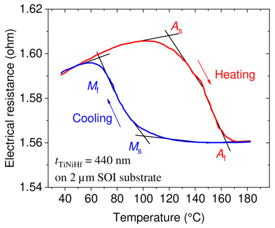
Figure 1.
Temperature-dependent electrical resistance characteristic of a 440 nm thick TiNiHf film on a 2 µm thick Si device layer of a SOI substrate. The start and finish austenitic and martensitic transformation temperatures (As = 119.3 °C, Af = 163.7 °C, Ms = 100.2 °C, Mf = 65.6 °C) are determined using the tangential method.
The cyclic heating and cooling of the material reveal the typical martensitic phase transformation temperatures in line with the transformation temperatures and thermal hysteresis values reported for sputtered freestanding TiNiHf films [13]. The complete hysteresis loop shows the full phase transformation of the TiNiHf material. The characteristic phase transformation temperatures are determined using the tangential method. The hysteresis width is determined via the difference of average transformation temperatures is 67 °C (, ).
3. Modelling and Design Approach
The shape memory effect is described using a 1D Tanaka-type model that has been extended to isotropic SMA materials of a 3D shape [14,15]. A variable for martensite phase fraction is used that approximates the kinetics of the phase transformation by an exponential step function depending on the temperature and stress. In the phase transformation regime between austenitic and martensitic states, the material properties are described using a rule of mixture [16]. For instance, the thermal expansion coefficient of TiNiHf is approximated as a mixture of thermal expansion coefficients of martensite and austenite :
For the simulation of temperature profiles, the stationary heat equation for the TiNiHf/Si cantilever beam is solved numerically by approximating the temperature-dependent heat conductivity of the two layers. The heat conductivity of TiNiHf is determined using the Wiedemann–Franz law [17] describing the heat conductivity of metals as a function of electrical conductivity σ:
with the proportionality constant [17]. The thermal conductivity of Si [18] is approximated using
Finite element simulations of the Joule heating of TiNiHf/Si cantilever actuators are performed by using COMSOL Multiphysics 6.0, which allows us to couple the models for the electrical current profiles and heat transfer. The resistive heating via electro-thermal coupling acts as a thermal stress on the solid–mechanics interface, causing differential thermal expansion as well as strain change due to martensitic phase transformation. The material properties of TiNiHf films are taken from a recent experimental study (See Table 1) [13]. The stress and electrical conductivity in the phase transformation regime are approximated using the rule of mixture as described before.

Table 1.
Material properties for coupled electro-thermo-mechanical simulation of temperature profiles for TiNiHf/Si bimorph microactuators. The Poisson ratio of Si is included in the COMSOL material library. A polynomial function approximates the thermal expansion coefficient of Si [18]: .
A double-beam cantilever design with two contact pads is chosen for the TiNiHf/Si microactuators, as it facilitates Joule heating. A major concern with direct Joule heating is the scaling effects of heat transfer. Due to rapid heat transfer at the onset of the cantilever beams, Joule heating results in a temperature gradient along the beams, showing the highest values at the beam tip and lowest values close to substrate at the beam onset. As a consequence of this in-homogenous temperature profile, the phase fraction of martensite varies along the beam; thus, all material properties depending on the phase fraction vary along the beam as well. In particular, some sections of the beam may have already transformed to austenite, while other sections may still be in a martensitic state. Consequently, a large electrical power is required to heat the entire beam above the phase transformation temperature of about 164 °C, and actuation stroke is reduced.
Figure 2 shows the simulated temperature profiles along the x-direction of a TiNiHf/Si cantilever beam for various values of electrical power. At 15 mW of electrical power, the reference design exhibits a maximum tip temperature of 247 °C, while the beam onset is near room temperature (Figure 2a,c). Consequently, only about 50% of SMA material has reached the austenitic finish temperature ( °C) and the remaining 50% remains in the martensitic state. Further increasing the electric power accumulates a large amount of heat at the cantilever tip and, thereby, increases the temperature gradient considerably. At 21.4 mW, the reference TiNiHf/Si design already reaches a temperature gradient of 8 °C/µm.
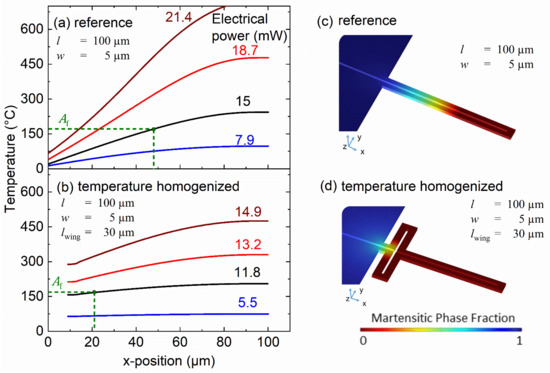
Figure 2.
(a,b): Coupled finite element simulation of the temperature profiles along x-direction of a TiNiHf/Si cantilever beam upon Joule heating for various values of electrical power. The beam length , beam width and length of folded beams are indicated. The reference design without additional folded beams shows much larger temperature gradients compared to the temperature-homogenized design with additional folded beams; (c,d): contour plots of martensite phase fraction for reference and temperature-homogenized design at an electrical power of 15 mW and 11.8 mW, respectively.
This disadvantage can be mitigated by the design of additional folded beams with a direction perpendicular to the active cantilever beams, giving rise to much more homogeneous temperature profiles, as shown in Figure 2b,d. Already at the electrical power of 11.8 mW, the maximum tip temperature reaches 210 °C, while only 22% of SMA material remains in a martensitic state. The maximum power required to complete the phase transformation is about 12.25 mW. Thus, the presented approach of temperature homogenization largely eliminates the issue of different phase states at local regions of the cantilever beam.
4. Fabrication of TiNiHf/Si Bimorph Microactuators
Figure 3 shows a schematic of the process flow for fabrication of the TiNiHf/Si microactuators. This process follows our previous approach of micromachining and nanomachining a SOI wafer prior to SMA film deposition. It has the advantage that the SMA’s functionality is not impaired by silicon technology and film delamination is prevented [22]. The starting substrate is a silicon-on-insulator (SOI) chip with a 2 μm device layer and 2 μm buried oxide layer. In the first steps, the pattern of cantilever beams is transferred to a chromium layer by using e-beam lithography (EBL) (Figure 3a,b) and a lift-off technique (Figure 3c). A chromium layer of 30 nm is used as a hard mask to etch the Si device layer via cryogenic reactive ion etching (RIE) (Figure 3d). In the next step, the chromium layer is removed, and the buried oxide layer is selectively removed via wet etching using hydrofluoric HF acid to obtain freestanding Si beam structures (Figure 3e). In the final step, the TiNiHf film is deposited via DC magnetron sputtering near room temperature to obtain freestanding TiNiHf/Si bimorph microstructures. Amorphous SMA films are then crystallized at 635 °C via rapid thermal annealing. Scanning electron micrographs of the fabricated TiNiHf /Si microactuators are shown in Figure 4. The TiNiHf layer of 440 µm and Si layers of 2 μm thickness can be distinguished clearly.
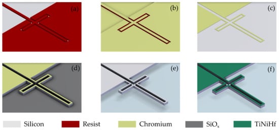
Figure 3.
Schematic process flow for fabrication of TiNiHf /Si microactuators using an SOI wafer with 2 μm Si device layer, (a) patterning of resist using EBL, (b) chromium deposition, (c) lift-off of chromium, (d) RIE of Si using cryogenic etching, (e) stripping of chromium and selective etching of SiOx sacrificial layer and (f) sputtering and annealing of TiNiHf thin film.
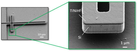
Figure 4.
Scanning electron micrographs of a freestanding TiNiHf /Si microactuator with folded beam structure for temperature homogenization. The thicknesses of the TiNiHf film and Si layer are 440 nm and 2 μm, respectively. Dimensions of cantilever beams: 75 μm length (), 3 μm width ( ) and 30 μm length of folded beam structure ( ).
5. Evaluation of Critical Electrical Power
Electrical resistance measurements are performed as a function of electrical power in situ in a scanning electron microscope (SEM) using the four-point method under stationary equilibrium conditions as described in Section 2. Nanomanipulators are used to establish electrical interconnections to individual microactuators as illustrated in Figure A1 in Appendix A. Figure 5 shows typical electrical resistance characteristics for different TiNiHf/Si microactuators without folded beam structures (reference design) and with folded beam structures for temperature homogenization. The electrical resistance characteristics show a complete hysteresis loop upon Joule heating and cooling, revealing the required electrical power for completing the phase transformation. Upon Joule heating, the average electrical resistance shows a characteristic drop for increasing electrical power, reflecting the course of the phase transformation. In the reference design, the resistance drop occurs gradually, as the phase transformation progresses gradually along the cantilever beam from the tip to the onset. In contrast, the temperature-homogenized design exhibits a much sharper drop in electrical resistance due to a larger volume fraction of SMA material transforming at a given heating power. In the present case (Figure 5a), the critical heating power required for a complete hysteresis loop reduces from 15 mW to about 11.8 mW corresponding to a reduction in power consumption by 21.8%. Figure 5b shows a comparison of TiNiHf /Si microactuators with different lengths of folded beam structures to illustrate their effect on temperature-homogenization. When increasing from 30 to 40 µm, the heating power required for complete phase transformation reduces from 7.9 to 5.5 mW, while the corresponding reference design requires about 10 mW. Thus, the reduction in power consumption reaches 45% in the latter case.
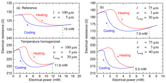
Figure 5.
In situ SEM measurement of electrical resistance as a function of electrical heating power for different TiNiHf/Si microactuators. The beam length , beam width and length of folded beams are indicated. The required electrical power to complete the phase transformation is highlighted. (a) Comparison of reference (top) and temperature-homogenized design (bottom), (b) temperature-homogenized design for different lengths of the folded beams ( ) of 30 and 40 µm.
Table 2 summarizes the results concerning the critical electrical power required for a complete hysteresis loop for each sample. By narrowing the width of the cantilever beams from 5 to 3 µm (compare samples Ref100, #1 and #2), an additional power saving from 21.8% to 48% is achieved. The reduced cross-section hinders heat transfer at the cantilever beam onset and, thus, favors temperature homogenization and power optimization. However, reducing the beam width for power optimization is limited largely by requirements on the mechanical performance of the microactuators. Increasing the length of the folded beams from 30 µm to 40 µm (compare samples Ref75, #3 and #4) increases the temperature-homogenization effect and enhances the power saving from 21% to 45%. A further increase in the folded beam length may further improve power saving, but might lead to mechanical instability. In addition, design limitations due to fabrication constraints have to be considered in this case.
Table 2.
Summary of experimental results of critical electrical power upon Joule heating required for a complete hysteresis loop and corresponding power saving for different geometries of TiNiHf/Si microactuators.
The temperature profile along the beam cannot be measured accurately due to size limitations. Therefore, we estimate the maximum temperatures at the cantilever tip by our simulations of Joule heating-induced temperature profiles. Figure 6 shows simulated maximum tip temperatures for TiNiHf/Si microactuators with two different beam lengths and widths. For instance, temperature-homogenized TiNiHf/Si microactuators with dimensions = 75 µm, = 3 µm and lwing = 30 µm show a maximum tip temperature of 212 °C at a power of 8 mW, while the reference microactuators show a maximum tip temperature of 230 °C at 10 mW. These results indicate that a lower heating power is required to reach a certain maximum tip temperature for the temperature homogenized design.
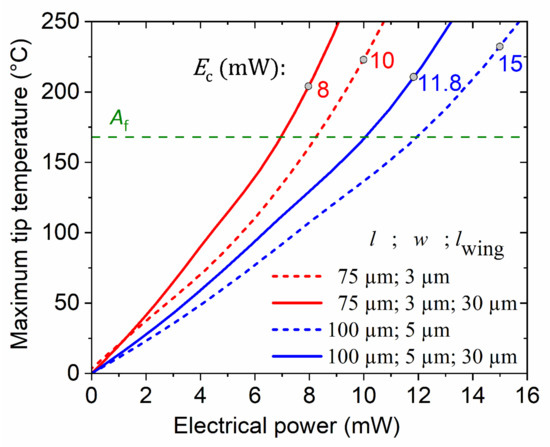
Figure 6.
Simulated characteristics of maximum temperature at the cantilever beam tip as a function of electrical heating power. Measured values of electrical power (dots) are compared to simulation results to estimate the maximum temperature at the cantilever beam tip.
6. Conclusions
In this work, we address the size-dependent effect of large temperature gradients upon direct Joule heating. We introduce a novel method to homogenize the temperature in cantilever-based SMA/Si microactuators by designing additional folded beams with a direction perpendicular to the active cantilever beams. This approach is evaluated for a series of TiNiHf/Si double-beam cantilevers that are fabricated by a combination of Si micromachining and magnetron sputter deposition of TiNiHf films. In situ electrical resistance measurements are performed to assess the critical electrical power required to achieve complete phase transformation for beam cantilevers with different beam lengths, widths, and lengths of additional folded beams. Our results reveal significant power savings of up to 48% compared to reference designs without temperature homogenization. We conclude that this approach of temperature homogenization largely eliminates the issue of inhomogeneous phase transformation along the beam cantilevers upon Joule heating. It discloses a simple measure for power optimization. In addition, the mechanical performance will be improved, as it also benefits from the larger fraction of SMA material undergoing the phase transformation.
Author Contributions
M.K. and E.Q. developed the concept; G.A. developed the simulation model, performed the simulations and experiments, analyzed the data and wrote the draft of the manuscript; Z.L. contributed to experiments and data analysis; S.M.C. and L.H. designed the TiNiHf experiments and analyzed the data; M.K. supervised the work, reviewed and edited the manuscript. All authors have read and agreed to the published version of the manuscript.
Funding
This research has received funding from the German Research Foundation (DFG) within the priority program “SPP2206—Cooperative Multistage Multistable Microactuator Systems”.
Data Availability Statement
The data presented in this study is available upon request from the corresponding author. They are not publicly available as they are being used in ongoing research.
Acknowledgments
This work was partly carried out with the support of the Karlsruhe Nano Micro Facility (KNMF, www.knmf.kit.edu), a Helmholtz Research Infrastructure at Karlsruhe Institute of Technology (KIT, www.kit.edu).
Conflicts of Interest
The authors declare no conflict of interest.
Abbreviations
The following abbreviations are used in this manuscript:
| EBL | Electron beam lithography |
| EDX | Energy-dispersive X-ray spectroscopy |
| FEM | Finite element modeling |
| MEMS | Micro-electro-mechanical systems |
| RIE | Reactive ion etching |
| SMA | Shape memory alloy |
| SOI | Silicon-on-insulator |
Appendix A

Figure A1.
Experimental setup used for in situ SEM measurements of electrical resistance. (a) Schematic of the chip layout consisting of many microactuators arranged in an array and electrical interconnections. Each microactuator has two contact pads (A and B) for electrical interconnection, whereby the contact pads A of each microcactuator are electrically connected with each other and with two large pads being interconnected via wire bonding. In addition, two nanomanipulators are used to establish electrical interconnections to the second contact pads B of each single microactuator in a time sequence one after another. (b) SEM images taken during in situ electrical measurement showing a single microactuator and the nanomanipulator tips used for electrical interconnection.
References
- Chollet, F. Devices based on co-integrated MEMS actuators and optical waveguide: A review. Micromachines 2016, 7, 18. [Google Scholar] [CrossRef] [PubMed]
- Du, H.; Chau, F.; Zhou, G. Mechanically-tunable photonic devices with on-chip integrated MEMS/NEMS actuators. Micromachines 2016, 7, 69. [Google Scholar] [CrossRef] [PubMed]
- Masmanidis, S.; Karabalin, R.; De Vlaminck, I.; Borghs, G.; Freeman, M.; Roukes, M. Multifunctional nanomechanical systems via tunably coupled piezoelectric actuation. Science 2007, 317, 780. [Google Scholar] [CrossRef] [PubMed]
- Guha, B.; Lipson, M. Controlling thermo-optic response in microresonators using bimaterial cantilevers. Opt. Lett. 2015, 40, 103. [Google Scholar] [CrossRef] [PubMed]
- Kim, P.; Hauer, B.; Clark, T.; Sani, F.F.; Freeman, M.; Davis, J. Magnetic actuation and feedback cooling of a cavity optomechanical torque sensor. Nat. Commun. 2017, 8, 1355. [Google Scholar] [CrossRef] [PubMed]
- Kohl, M. Shape Memory Microactuators; Springer: Berlin/Heidelberg, Germany, 2004. [Google Scholar]
- Miyazaki, S.; Fu, Y.; Huang, W. (Eds.) Thin Film Shape Memory Alloys: Fundamentals and Device Applications; Cambridge University Press: Cambridge, UK, 2009. [Google Scholar]
- Stachiv, I.; Alarcon, E.; Lamac, M. Shape memory alloys and polymers for MEMS/NEMS applications: Review on recent findings and challenges in design, preparation, and characterization. Metals 2016, 11, 415. [Google Scholar] [CrossRef]
- Lay, C.; Aseguinolaza, I.; Chernenko, V.; Kohl, M. Development of ferromagnetic shape memory alloy–silicon bimorph nanoactuators. In Proceedings of the 13th IEEE Conference in Nanotechnology (IEEE-NANO), Beijing, China, 5–8 August 2013. [Google Scholar]
- Kohl, M.; Schmitt, M.; Backen, A.; Schultz, L.; Krevet, B.; Fähler, S. Ni-Mn-Ga shape memory nanoactuation. Appl. Phys. Lett. 2014, 104, 4. [Google Scholar] [CrossRef]
- Lambrecht, F.; Aseguinolaza, I.; Chernenko, V.; Kohl, M. Integrated SMA-based NEMS actuator for optical switching. In Proceedings of the 29th IEEE International Conference on Micro Electro Mechanical Systems (MEMS), Shanghai, China, 24–28 January 2016. [Google Scholar]
- Rastjoo, S.; Fechner, R.; Bumke, L.; Kötz, M.; Quandt, E.; Kohl, M. Development and co-integration of a SMA/Si bimorph nanoactuator for Si photonic circuits. Microelectron. Eng. 2020, 225, 111257. [Google Scholar] [CrossRef]
- Curtis, S.; Sielenkämper, M.; Arivanandhan, G.; Dengiz, D.; Li, Z.; Jetter, J.; Hanke, L.; Bumke, L.; Quandt, E.; Wulfinghoff, S.; et al. TiNiHf/SiO2/Si shape memory film composites for bi-directional micro actuation. Int. J. Smart Nano Mater. 2022, 13, 293–314. [Google Scholar] [CrossRef]
- Tanaka, K.; Nagaki, S. A thermomechanical description of materials with internal variables in the process of phase transitions. Ing. Arch. 1982, 51, 287–299. [Google Scholar] [CrossRef]
- Tanaka, K. A thermomechanical sketch of shape memory effect: One-dimensional tensile behavior. Res. Mech. 1986, 18, 251–263. [Google Scholar]
- Kohl, M.; Krevet, B. 3D Simulation of a Shape Memory Microactuator. Mater. Trans. 2002, 43, 1030–1036. [Google Scholar] [CrossRef]
- Kopitzki, K.; Herzog, P. Einführung in die Festkörperphysik, 5th ed.; Teubner: Stuttgart, Germany, 2004. [Google Scholar]
- Carruthers, J.A.; Geballe, T.H.; Rosenberg, H.M.; Ziman, J.M. The thermal conductivity of germanium and silicon between 2 and 300° K. Math. Phys. Sci. 1957, 238, 502–514. [Google Scholar]
- Watanabe, H.; Yamada, N.; Okaji, M. Linear thermal expansion coefficient of silicon from 293 to 1000 K. Int. J. Thermophys. 2004, 25, 221–236. [Google Scholar] [CrossRef]
- Jeong, J. Evaluation of elastic properties and temperature effects in Si thin films using an electrostatic microresonator. J. Microelectromech. Syst. 2003, 12, 524–530. [Google Scholar] [CrossRef]
- Benafan, O. Deformation and Phase Transformation Processes in Polycrystalline NiTi and NiTiHf High Temperature Shape Memory Alloys. Ph.D. Thesis, University of Central Florida, Orlando, FL, USA, 2012. [Google Scholar]
- Lay, C.; Aseguinolaza, I.; Chernenko, V.; Kohl, M. In-situ characterization of ferromagnetic shape memory alloy/silicon bimorph nanoactuators. In Proceedings of the 14th IEEE International Conference on Nanotechnology, Toronto, ON, Canada, 18–21 August 2014; pp. 192–195. [Google Scholar]
Disclaimer/Publisher’s Note: The statements, opinions and data contained in all publications are solely those of the individual author(s) and contributor(s) and not of MDPI and/or the editor(s). MDPI and/or the editor(s) disclaim responsibility for any injury to people or property resulting from any ideas, methods, instructions or products referred to in the content. |
© 2023 by the authors. Licensee MDPI, Basel, Switzerland. This article is an open access article distributed under the terms and conditions of the Creative Commons Attribution (CC BY) license (https://creativecommons.org/licenses/by/4.0/).