Article

System-Level Modelling and Simulation of a Multiphysical Kick and Catch Actuator System

1
Jade University of Applied Sciences, Friedrich-Paffrath-Str. 101, 26389 Wilhelmshaven, Germany
2
Chair of Control Engineering, University of Augsburg, Eichleitnerstr. 30, 86159 Augsburg, Germany
*
Author to whom correspondence should be addressed.
Actuators 2021, 10(11), 279; https://doi.org/10.3390/act10110279
Submission received: 30 June 2021 / Revised: 8 October 2021 / Accepted: 19 October 2021 / Published: 21 October 2021
(This article belongs to the Special Issue Cooperative Microactuator Systems)

Abstract

:
This paper presents a system-level model of a microsystem architecture deploying cooperating microactuators. An assembly of a piezoelectric kick-actuator and an electromagnetic catch-actuator manipulates a structurally unconnected, magnetized micromirror. The absence of mechanical connections allows for large deflections and multistability. Closed-loop feedback control allows this setup to achieve high accuracy, but requires fast and precise system-level models of each component. Such models can be generated directly from large-scale finite element (FE) models via mathematical methods of model order reduction (MOR). A special challenge lies in reducing a nonlinear multiphysical FE model of a piezoelectric kick-actuator and its mechanical contact to a micromirror, which is modeled as a rigid body. We propose to separate the actuator–micromirror system into two single-body systems. This step allows us to apply the contact-induced forces as inputs to each sub-system and, thus, avoid the nonlinear FE model. Rather, we have the linear model with nonlinear input, to which established linear MOR methods can be applied. Comparisons between the reference FE model and the reduced order model demonstrate the feasibility of the proposed methodology. Finally, a system-level simulation of the whole assembly, including two actuators, a micromirror and a simple control circuitry, is presented.

1. Introduction

Micromirrors and microscanners are key technologies for numerous optical applications, including laser projection [1], optical communication [2], displays [3,4,5,6,7], medical imaging [8,9], and light detection and ranging (LiDAR) [10,11,12,13]. This widest range of varying applications is down to their superior production costs, compact dimensions, and energy efficiency. A consequence of their popularity is the number of designs, which are commonly categorized by their actuation principle and degrees of freedom (DOFs). Actuating a micromirror typically employs either electrostatic [3,6], piezoelectric [14], electromagnetic [7,15,16], or thermoelectric [17,18] effects. These physical effects mainly differ in speed of actuation, displacement magnitude, required space and operating voltage. A micromirror’s DOFs determine its number of rotational and potentially translational axes. Each design features its own maximum deflection angle and operating frequencies.
However, all these concepts share one common design aspect: the rotating mirror is mounted using structural connections as there are no ball bearings in microtechnology. Consequently, these links restrict the maximum deflection angle and cause restoring forces that the actuator has to overcome. This deficit limits the classical micromirror’s use in certain applications, such as tracking, as they require large quasistatic deflections [19,20].
A novel actuator design has been proposed to overcome this limitation by omitting all structural suspensions [20]. In contrast, an unconnected hemispherical micromirror is rotated by periodic bouncing elicited by contact to an elliptically oscillating stage. This design achieves a resonant deflection angle of ± 35.2 and a maximum angular velocity of 732 s [20]. As each contact induces rotational momentum, stepwise rotation is achieved. Up till now, challenging physics such as mechanical contact impede accurate modeling and closed-loop control, limiting the approach to a proof of concept.
The kick and catch research project [21] aims to extend this innovative system by more sophisticated actuators and highly accurate models, enabling model-based closed-loop control [22,23,24]. In this approach, a cooperation of a kick-actuator and a catch-actuator achieves multistable motion of the hemisphere. The former corresponds to a more sophisticated version of the stage [
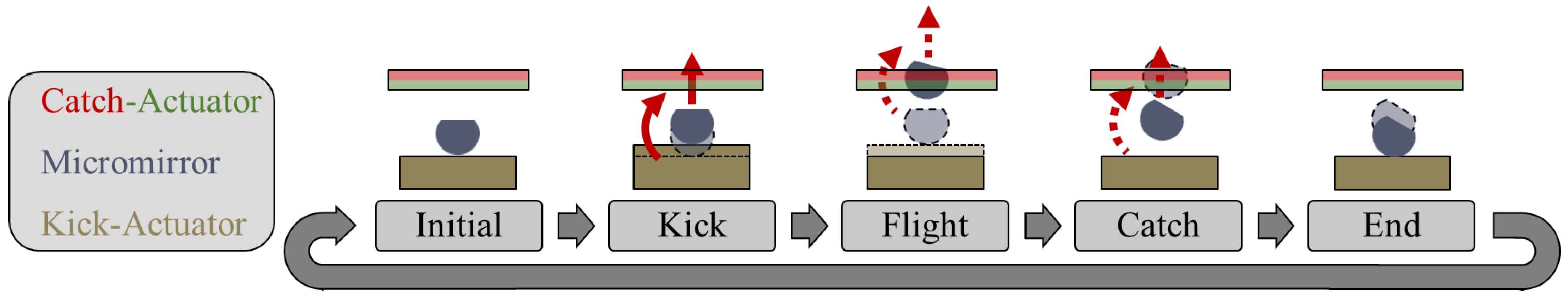
20], offering more control of the hemisphere’s launch and landing; The latter introduces controllable forces acting on the hemisphere, thus providing access to the closed-loop control. Figure 1 illustrates the concept’s basic operating principle: first, the piezoelectric kick-actuator expands. Mechanical contact transfers these sudden forces to the micromirror, launching it into a flight phase with potential rotation. During the flight, the electromagnetic catch-actuator adjusts the hemisphere’s trajectory and softens its landing. Finally, the rotated micromirror lands on the kick-actuator. Repeating this sequence achieves larger rotations.
As optical applications require high-level accuracy, reliable system-level models are of crucial importance. This is especially true for the kick-actuator due to its mechanical contact to the hemisphere as well as its multiphysical actuation. The finite element method (FEM) allows the accurate modeling of these effects, but its computational demand prevents any system-level application.
This gap is closed by MOR methodology [25], generating system-level models of extraordinary accuracy based on, for example, finite element (FE) models. MOR reduces a model’s initially high dimension by several orders of magnitude while forfeiting almost no precision. Methods to generate reduced order models (ROMs) are well established for linear systems [26], whereas mechanical contact remains challenging due to its nonlinearity and inequality constraints [27]. Another obstacle in reducing contact are mainly its three different FE implementations: Lagrange multipliers, penalty, or augmented Lagrange multipliers [28]. To enforce non-penetration, they introduce additional DOFs, penetration-opposing stiffness, or both.
General nonlinear MOR is accompanied by two particular problems: finding a reduced basis and efficiently evaluating nonlinearities [29]. The data-driven proper orthogonal decomposition (POD) [27,30,31,32] is the state-of-the-art method for constructing a reduced basis for a nonlinear system. Techniques [33] that do not rely on data created by extensive simulations, such as modal [34] or static derivatives, are less popular. A recent contact-specific approach separates the DOFs of the full order model (FOM) into displacements and Lagrange multipliers prior to reduction, relying on Lagrange-like contact implementation [27,35]. Evaluating nonlinearities is accompanied by extremely high computational costs and must thus be approximated to maintain the ROM’s efficiency. This approximation step is known as hyper-reduction, estimating the full nonlinearity based on few local evaluations [29]. Prominent methods include the data-driven discrete empirical interpolation method (DEIM) [36] and the technique of energy conserving mesh sampling and weighting (ECSW) [27,31,37,38]. Although these methods can achieve excellent precision even for contact problems [27,31,39], they require numerous expensive FOM solutions, also referred to as snapshots. Moreover, their prediction quality is limited to cases included in their training, making data-driven ROMs less robust.
A noteworthy technique exists for reducing systems with their nonlinearities exclusively in their input, which are referred to as weakly nonlinear systems. In this case, the inputs can be grouped to reduce the number of nonlinearities [40]. The inputs of a mechanical system are external forces and grouping inputs means merging almost equal forces into a single but distributed force. The reduced number of forces allows them to be efficiently handled as nonlinear inputs for a linear ROM. Although this approach requires simple geometries, a-priori knowledge of the forces’ location and mergeable forces, it offers two remarkable advantages: firstly, in contrast to state-of-the-art data-driven MOR, it does not rely on computationally expensive snapshots. Consequently, such an ROM is not restricted by its training input. Secondly, well-established methods of linear MOR, such as Krylov-subspace-generated bases [41], become available. This also includes robust methods for parametric model order reduction (pMOR), enabling the inclusion of parameters arising from material properties or geometry.
This paper applies the aforementioned reduction of weakly nonlinear systems to an impact problem on a piezoelectric kick-actuator. Hence, the method’s scope is extended from contact as a boundary condition [40] to penalty-based contact between two bodies. The novel approach for this extension is to separate the kick-actuator and a sphere into individual models. The model of the kick-actuator is reduced separately and is rejoined with the sphere via contact at the system-level. This separation relocates the multibody system’s nonlinearity from the stiffness matrix to the individual systems’ inputs. Hence, penalty-based contact can be considered nonlinear external forces, granting access to the methodology of [40]. Further enhancement is provided through considering the expected load distribution in the FE mesh’s design. As a result, the grouping-induced error is reduced compared to [40]. The final ROM complements preceding work on the electromagnetic catch-actuator [23,24] and enables system-level simulation of the entire actuator system.
The remainder of this paper is structured as follows: Section 2 provides more details on the actuator system, its FE models, their reduction by means of MOR, and a final application at system-level, demonstrating feasibility. Numerical experiments evaluate the ROM’s accuracy and computational efficiency by comparing its solution to the reference. Both intermediate and final results are presented in Section 3. Finally, Section 4 offers a conclusion and identifies aspects for future investigation.

2. Materials and Methods

This section specifies the design of the kick and catch actuator system and introduces simplifications applied in this study. Subsequently, FE models of the piezoelectric kick-actuator and the electromagnetic catch-actuator are described. MOR generates system-level models deployed in a full system-level simulation. The catch-actuator has been the subject of earlier work [23,24]. Corresponding paragraphs will, therefore, be confined to summaries and updates.

2.1. Actuator System Design

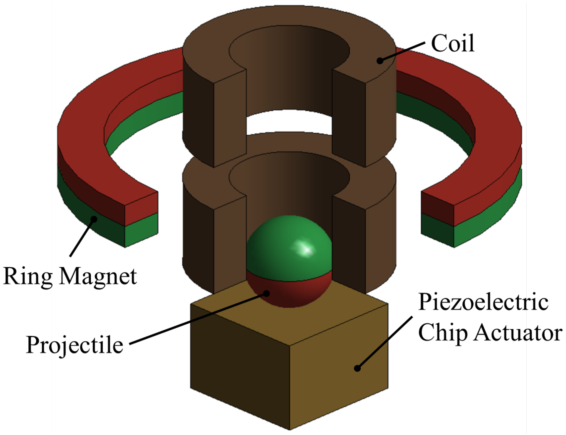
The kick and catch actuator system constitutes an innovative architecture for micromirrors as it omits all structural connections. Due to this work’s focus being on methods of nonlinear MOR, the system is simplified as shown in Figure 2:
  • A sphere replaces the hemisphere;
  • The sphere’s motion is restricted to vertical displacement;
  • The kick-actuator comprises a single piezoelectric chip actuator;
  • All of the components are arranged concentrically.
Even though the mirror’s rotation is not modeled, these changes do not neglect physical effects and include the working principle shown in Figure 1: the expanding piezoelectric kick-actuator accelerates the sphere via mechanical contact. Subsequently, the catch-actuator controls the magnetic sphere’s position via electromagnetic forces. Therefore, the setup suffices to develop methods for generating system-level models. In addition, preliminary experiments are planned using the same configuration. For that reason, all of the components were chosen from those commercially available.
For the kick-actuator, a piezoelectric PA3JEAW chip actuator by Thorlabs is deployed. A total of 33 piezoelectric layers of lead zirconate titanate (PZT)-based THP51 [42] with alternating polarization stack up to a chip actuator of ( 3 × 3 × 2 ) m m 3 . Silver electrodes in between collect or distribute electric charges. A ceramic coating prevents moisture from entering the actuator. Appendix A.2 presents all material data relevant for simulation.
The magnets employ commercial products, whereas the coils will be custom-manufactured. Table 1 denotes the cylindrical parts’ dimensions and their vertical positions. Leaving a radial gap for potential guiding structures, the coils’ inner radii are chosen to be 1.3   m m . The two coils’ geometries are identical and deploy a copper wire with a diameter of D W = 25   μ m . Each solenoid comprises 4074 windings, assuming a fill factor of 100%.
Although the setup of this work is macro-scale, a miniaturization is targeted in the long term. A corresponding design will presumably rely on following cornerstones: microcoils might be manufactured by wirebonding technology from IMTEK, Freiburg. Stacked layers of metglas allow for magnets with tailored properties. Additional mechanical leverage might extend the stroke of piezoelectric actuators.

2.2. Finite Element Models

In general, physical problems are rendered into partial differential equations (PDEs) ones that can rarely be solved analytically. The FEM spatially discretizes the computational domain, transforming a PDE into a large-scale system of ordinary differential equations (ODEs). In addition, numerical integration schemes discretize time and thus transform the system of ODEs into a system of algebraic equations. Therefore, methods of linear algebra can solve the initial physical problem. If properties of the system depend on its solution, the system is classified as nonlinear. In this case, the solution process deploys iterative schemes where each iteration solves a linearized system. For a transient analysis, these iterations arise at each time step, multiplying computational effort.
The actuator system comprises two single actuators with distinct physical domains. While the catch-actuator is an electromagnetic scenario, the kick-actuator relies on piezoelectricity and contact mechanics. As the physics of the two actuators do not effectively interfere with each other, they were investigated in separate FE analyses. All electromagnetic analyses were conducted in ANSYS Maxwell 2020 R2, all piezoelectric analyses in ANSYS Mechanical 2020 R2 and all system-level simulations in ANSYS TwinBuilder 2020 R2. A system of an AMD Ryzen 5 3600 and 16 GB RAM was employed for all analyses.

2.2.1. Electromagnetic Catch-Actuator

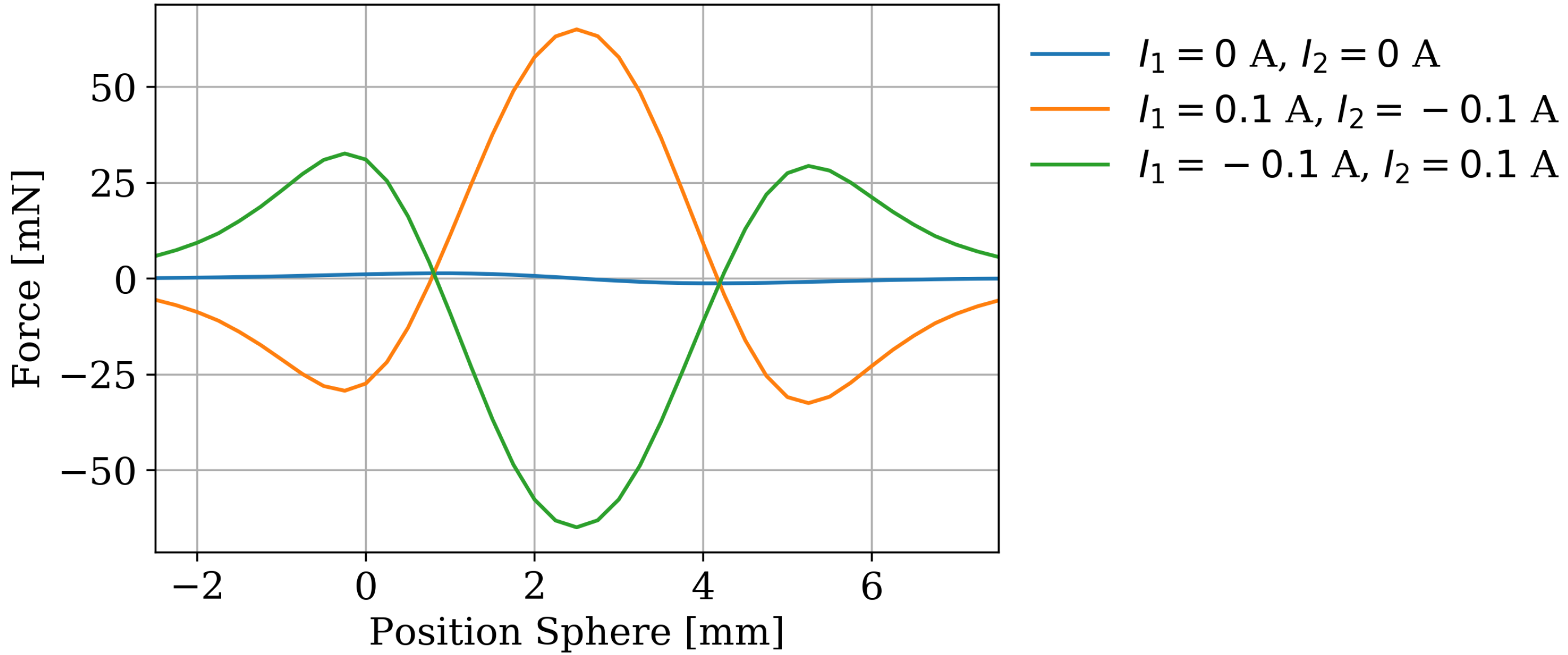
The catch-actuator electromagnetically controls the micromirror’s position and orientation. Simplifying the device as described in Section 2.1, the mirror is exchanged with a sphere and restricted to vertical motion. Consequently, the catch-actuator interacts with the sphere via a vertical force. This electromagnetic force depends predominantly on the sphere’s vertical position and the electrical currents in the solenoids. Transient effects can be ignored.
The catch-actuator’s FE model exploits its rotational symmetry, allowing a two-dimensional analysis setup. An enclosing air region is introduced in addition to the geometries of the magnet, the coils and the sphere. This region represents the air between the components and in their surroundings, taking the far field into account. Its geometry in three dimensions corresponds to a cylinder of R = 10   m m and H = 30   m m , centered around the actuator. All material data are given in Table A1 and assumed to be linear, reducing the complexity of a later system-level model. As mesh resolution is crucial for a FE analysis’ accuracy, adaptive meshing is applied. This process convergence criteria are set to either a maximal relative error of 5 ∗ 10-6 or 30 iterations. To compute the electromagnetic force on the sphere with respect to its dependencies, both coil currents and the sphere’s position are parameterized. The sphere’s vertical position ranges from −2.5 m m to 7.5 m m in 41 steps, the coil currents from −0.1 A to 0.1 A in increments of 0.1   A . Finally, the catch-actuator is analyzed in a set of 369 static electromagnetic simulations. A more extensive description is available in [23,24].

2.2.2. Piezoelectric Kick-Actuator

The kick-actuator launches the hemispherical mirror by a sudden transfer of momentum and also serves as a landing platform. In the context of this work, the PA3JEAW actuator launches a rigid sphere in response to an electrical excitation. Although simplified, this sequence features transient multiphysics and nonlinearities due to piezoelectricity and mechanical contact.
The modeled geometry represents the piezoelectric chip actuator defined in Section 2.1. Both the ceramic coating and the electrodes have little influence on the actuator’s mechanical behavior. Therefore, their geometry is excluded from the model. All electrodes are considered ideally conductive, allowing for coupling electrical DOFs of all anodes and cathodes respectively. Moreover, the cathode is grounded and electric loads may be applied to the anode. The 33 piezoelectric layers of alternating polarization are modeled as one block of THP51. A mapped layered mesh reintroduces their structure and Appendix A.2 provides the THP51’s material data. The sphere is considered rigid to reduce complexity of nonlinear iterations. Thus, only the sphere’s density of ρ = 7850 k g m 3 
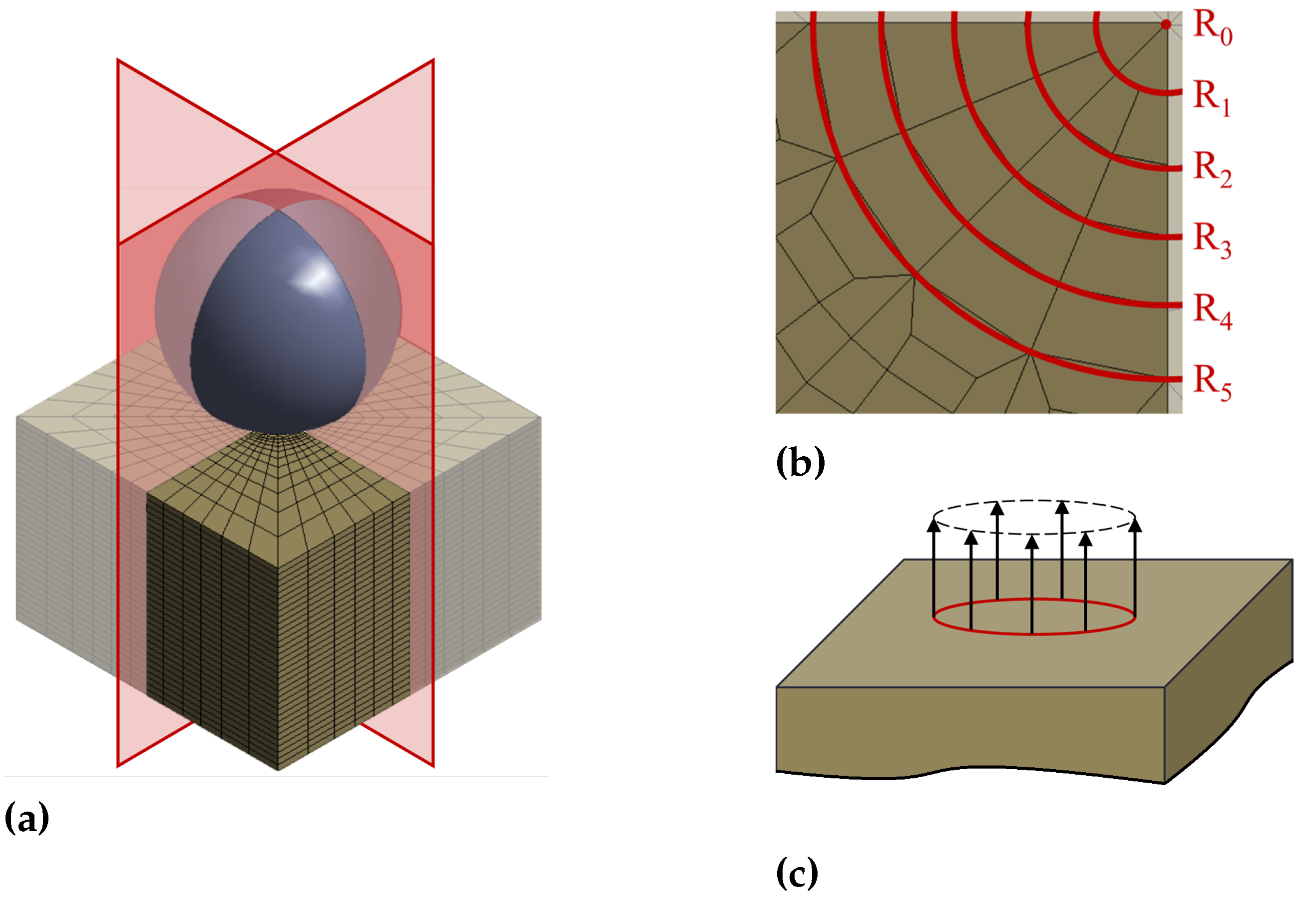
remains relevant. In addition, several symmetries are introduced by restricting the sphere to vertical motion. As a result, modeling a quarter of the setup as shown in Figure 3a suffices, significantly saving computational resources. This is particularly useful for transient nonlinear analyses. Furthermore, any vertical displacement of the bottom face is set to zero, representing an adhesive connection. Additional displacement constraints prevent rigid body motion of the chip actuator. Simulating initial rigid body motion in impact setups brings no insights at full computational costs for each time step. To minimize this issue, the sphere is modeled 1 μm above the actuator’s top surface and assigned an initial velocity. The transient analysis deploys an implicit Newmark time integration with a time-step of 50 ns to an end time of 15 μs.
The chip actuator is spatially discretized into a linear mapped FE mesh for three reasons: firstly, a mapped mesh allows to accurately model the piezoelectric layers. Secondly, a mapped instead of a free mesh avoids numerically induced asymmetries in the contact forces. Thirdly, and most importantly, this part of the mesh is the basis for efficiently reducing contact. The procedure in [40] groups together nodes of equal external forces. Hence, it is crucially important to have a mesh that supports such clustering. As a sphere causes the contact forces, locations on a concentric circle experience effectively equal vertical forces. No radial forces occur due to settings chosen for contact modeling. Therefore, meshing the contact area in five concentric rings as illustrated in Figure 3b is an appropriate choice. The rings have a radial distance of 50 μm as a fine mesh in contact regions improves accuracy and nonlinear convergence.
Excluding contact and the sphere for now, the kick-actuator constitutes a linear piezoelectric problem. Employing a strong coupling, such a system is governed by a system ΣP of ODEs expressed as:
Σ P = M x x 0 0 0 M x ¨ V ¨ x ¨ + E x x 0 0 0 E x ˙ V ˙ x ˙ + K x x K x V K V x K V V K x V x = f = B x B V B u y = C x C V C x V ,
where M , E , K R n × n are the mass, damping and stiffness matrices. The blockmatrices’ subscripts indicate their physical domain: “ x x ” corresponds to structural mechanics, “ V V ” to electrics and “ x V ”/“ V x ” to their coupling. Consequently, the state vector x R n incorporates n x nodal displacements x R n x and n V nodal electrical potentials V R n V . Further, the input vector is denoted by u R p , the user-defined output vector by y R q . The matrix B R n × p distributes the inputs, whereas C R q × n computes the outputs. From a physical perspective, the columns of B contain “force shapes” that are scaled by u . Thus, their product B u equals a vector of total external forces f R n . When using Rayleigh damping, the mechanical damping matrix E x x R n × n is given as a weighted sum of mass and stiffness matrix. With constant Rayleigh coefficients α and β , the relation is expressed by:
E x x = α M x x + β K x x .
Contact in FE analyses adds two steps to the solution process [27]: first, the solver checks for contact. If contact is detected, non-penetration is enforced via nonlinear iterations. Three methods have been established to handle this constraint: Lagrange multipliers, penalty and augmented Lagrange multipliers. This work deploys the penalty method which introduces virtual springs opposing penetration. Their force depends linearly on the penetrating volume or distance and vanishes as soon as the bodies leave contact. Although this method tolerates small penetrations and may cause ill-conditioning, it offers superior convergence and does not introduce new DOF [43]. A constant contact stiffness of 100,000 N mm has been chosen. The setup is assumed to be frictionless, as friction barely contributes due to the model’s simplifications. This assumption might not yield accurate results for more complex scenarios. Further, adhesion is neglected as corresponding physical effects do not contribute in relevant orders of magnitude.
Contact occurs if the distance d ( x ) R N C between certain nodes falls below zero. Mathematically, this condition is denoted by the following inequality constraints [39,44]:
d ( x ) = B C x + g 0 0 ,
where each row represents one of the N C inequality constraints. The matrix B C R N C × n selects nodal displacements for each constraint and g 0 R N C denotes initial gap sizes. Since x is unknown, the contact status can only be determined upon solution. Therefore, the contact is adjusted in iterative solutions until convergence. If d ( x ) < 0 , penetration occurs and Equation (3) is violated. In this case, the penalty algorithm introduces counteracting forces f P e n a l t y ( x ) , approximately restoring d ( x ) 0 . Only violated constraints are enforced and thus contact forces are applied to a corresponding subset N C of all N C constraints. These forces linearly depend on penetration via a penalty stiffness ε and read as:
f P e n a l t y ( x ) = ε B C , v T d v ( x ) = ε B C , v T B C , v K C ( x ) x + ε B C , v T g 0 , v f C ( x ) if violated 0 else .
Here, the subscript “ v ” denotes subsets of respective quantities that exclusively contain violated constraints. Since detecting constraint violations requires the solution, the subsets depend on x and may change for each iteration. Rewriting the forces as contact stiffness K C R n × n and contact force f C R n emphasizes their physical interpretation as additional stiffness. Their nonlinearity is indicated as a function of x , replacing their subscript “ v ”. Combining Equations (1) and (4) provides the system Σ P C of piezoelectric contact as:
Σ P C = M x ¨ + E x ˙ + K + K C ( x ) x = f f C ( x ) y = C x .
Contact analyses usually feature multiple bodies that do not interact until they are in contact. Therefore, all system matrices are block diagonal until contact introduces K C ( x ) , coupling the bodies. In the case of a rigid body, its blocks in the system matrices are of dimension R 1 × 1 .

2.3. Model Order Reduction

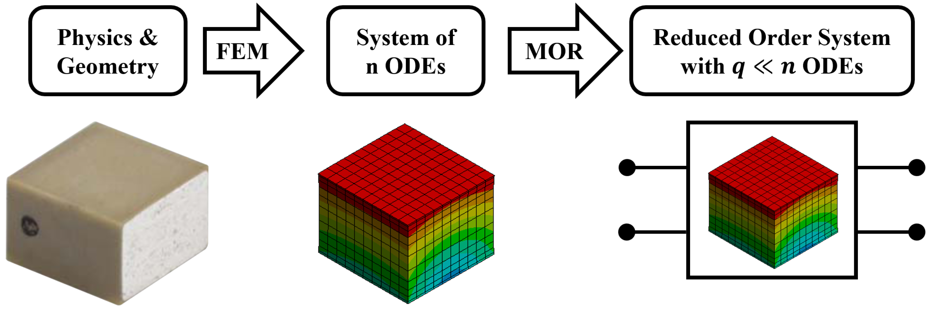
MOR approximates a large-scale system by an ROM of a drastically smaller dimension. The ROM hardly forfeits any accuracy while providing a speed-up of several orders of magnitude. FE solvers are a natural application for MOR, as they assemble and solve large-scale systems of ODEs. Figure 4 illustrates this idea for the piezoelectric kick-actuator.
One robust and accurate method for linear models is projecting a large-scale system onto a low-dimensional Krylov subspace [41,46]. For this approach, the state vector x is expressed as:
x = V x r + ε ,
where V R n × q is the orthogonal basis of the corresponding Krylov subspace and x r R q is the reduced state vector. The approximation error ε R n is cut off and contains the part of x that does not lie in the Krylov subspace. The subspace’s basis vectors may be orthonormalized by the block Arnoldi algorithm. Its dimension q is several orders of magnitude smaller than n, that is, q n . Projecting the linear second order system Σ P in Equation (1) onto V , one obtains the reduced model:
Σ P r = V T M V M r x ¨ r + V T E V E r x ˙ r + V T K V K r x r = V T B B r u y = C V C r x r .
The projection significantly reduces the system’s dimension to x r R r , M r , E r , K r R r × r , B r R r × p and C r R q × r . In addition, the reduction preserves all inputs u and outputs y . However, the projected system lacks physical meaning.
MOR expresses the state vector x as a linear combination of predefined “shapes” (columns of V ). Further, the reduced state vector corresponds to the weights of each shape. From a mathematical perspective, Krylov subspace-based MOR matches the Taylor expansions of the ROM’s and the FOM’s transfer functions around a frequency s 0 for the first q moments.
However, such reduction of multiphysical systems does not necessarily preserve its stability [47,48,49]. Therefore, Schur after MOR [48] is applied to reintroduce stability to the piezoelectric system’s ROM. Translating the reduced system into very high speed integrated circuit hardware description language (VHDL) creates a convenient interface to commercial system-level simulation software.
As mentioned in Section 1, additional challenges accompany nonlinear MOR as a nonlinear system cannot be directly reduced. If the nonlinearities can be moved to the input, methods of linear MOR can be applied. In this case, the ROM evaluates the same nonlinear forces as the FOM. However, efficiency decreases with each nonlinear evaluation. If some nonlinear forces are almost the same, they can be approximated by computing a single force and distributing it to relevant nodes [40]. Therefore, the number of nonlinearities is reduced and the ROM gains efficiency. Obviously, the grouping process introduces errors depending on how similar the forces are. An appropriately designed mesh diminishes the error and also supports the choice of which forces to group.
However, penalty-based contact not only introduces nonlinear external forces, but also a nonlinear stiffness matrix as shown in Equation (5). The method of [40] only applies to the former, but cannot handle the latter. Compatibility can be achieved by separately modeling and reducing the bodies. The separation recasts the nonlinear coupling within the stiffness matrix of the multibody system into external nonlinear forces of the separated systems. Subsequently, these forces can be grouped for each body as proposed in [40]. Since the sphere is considered rigid and is restricted to vertical motion, it can be represented by a point mass. Moreover, its dynamics only depend on the total vertical contact force.
Therefore, only contact forces acting on the kick-actuator must be grouped. Because these forces result from contact to a sphere, circles around the center of impact each have almost identical vertical forces, as shown in Figure 3c. In addition, a FE mesh of a center node and five concentric rings as displayed in Figure 3b minimizes errors and facilitates the grouping process. The vertical forces are grouped for each ring, resulting in a total of six penetration-dependent forces. To compute the penetrations, the system’s outputs must include all the rings’ vertical displacements. Furthermore, the kick-actuator also requires the electric charge on the actuator’s coupled anodes Q A n o d e as an input and their voltage V A n o d e as an output. The resulting weakly nonlinear system Σ K A of the kick-actuator is given by:
Σ K A = M x ¨ + E x ˙ + K x = B u x , u Y , S ) y = C x ,
u ( x , u Y , S ) = F C , R 0 ( u Y , R 0 , u Y , S ) F C , R 5 ( u Y , R 5 , u Y , S ) Q A n o d e , y = u Y , R 0 u Y , R 5 V A n o d e .
The differences to the general piezoelectric system in Equation (1) are the system’s inputs and outputs. The output vector y includes all rings’ vertical displacements u Y , R i as they are required to compute the penetrations. The output matrix B includes six normalized ring-based force shapes as illustrated in Figure 3c and the electric charge distribution on the anodes. Accordingly, the nonlinear input vector u ( x , u Y , S ) scales each force shape by the corresponding ring’s total contact force F C , R i ( x , u Y , S ) . For a ring R i , this force depends on the kick-actuator’s deformation x and the position of the sphere u Y , S ; it is denoted by:
F C , R i ( u Y , R i , u Y , S ) = ε u Y , S u Y , R i + g 0 , R i for penetration at R i 0 else ,
where u Y , R i is the vertical displacement of ring R i and g 0 , R i is the initial vertical gap between the ring and the sphere.

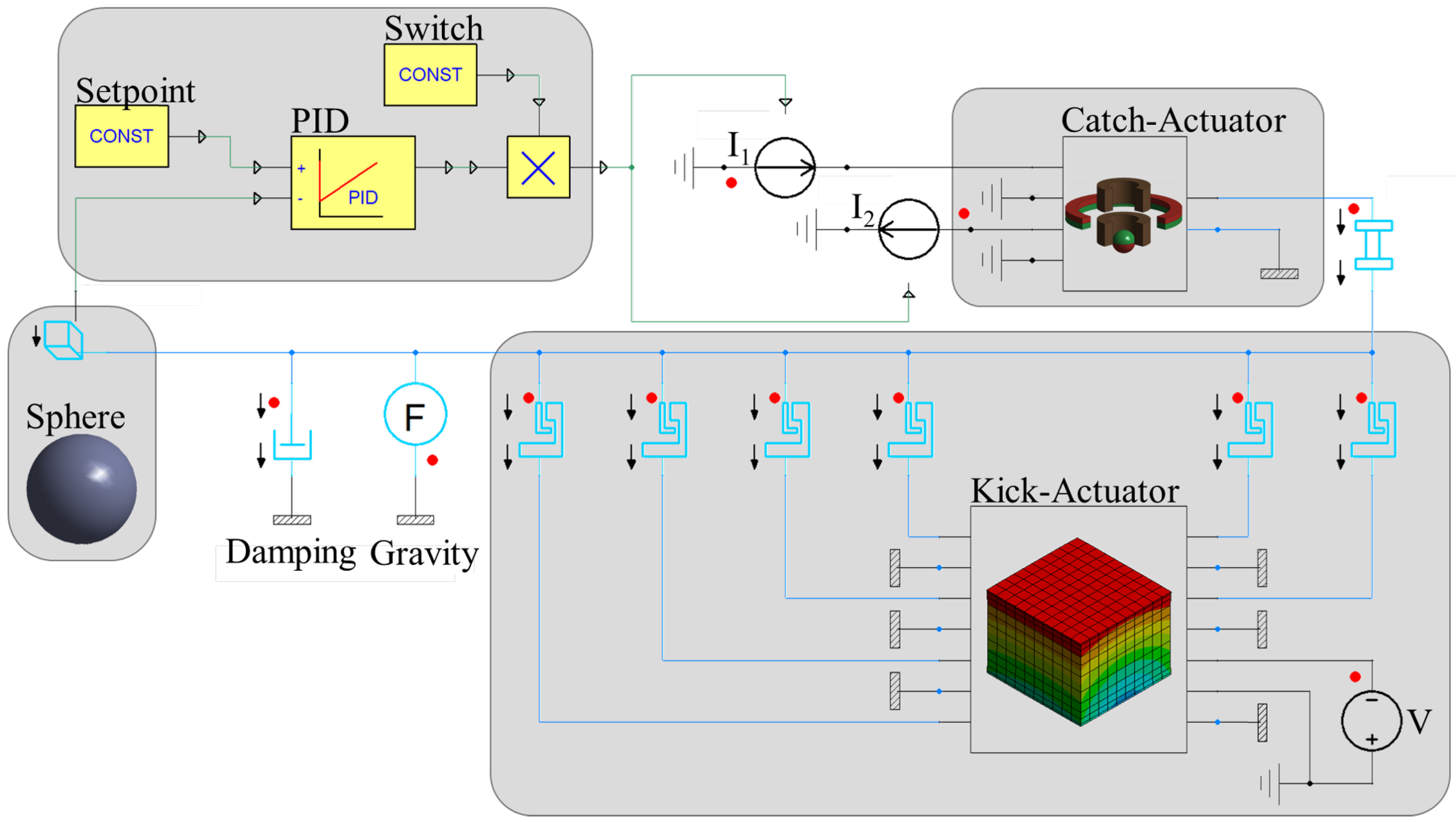
2.4. System-Level Simulation

This section deploys a full system-level simulation of the simplified kick and catch actuator system, demonstrating feasibility. System-level simulation is highly beneficial for several reasons: first, the simulations are multiple orders of magnitude faster than at device-level with comparable accuracy. This speed-up allows us to efficiently study different load cases. Further, sub-models from different physical domains can be combined. In addition, co-simulation with driving/control circuitry becomes feasible, thus improving the system’s development as a whole. Although the output quantities have to be chosen beforehand, every quantity involved in the calculation can be promoted to an output.
In order to model the actuator system, the kick-actuator’s ROM and the sphere’s point mass are coupled via six lumped contact springs. Each spring represents a single ring’s vertical contact. If a spring detects penetration, it applies a corresponding force to the two bodies. For the kick-actuator’s ROM, each spring force scales its corresponding force shape as indicated in Figure 3c.
After contact is reestablished, an equivalent circuit (EC) of the electromagnetic catch-actuator complements the actuator system. An EC is a lookup table based on parametric simulation and is an industrial standard method. Here, the EC provides the electromagnetic force on the sphere with respect to its vertical position and the two coil currents. Section 2.2.1 describes each parameter’s range and resolution.
A PID-based closed-loop control of the kicked sphere’s position constitutes a representative application. The global coordinate system’s origin is located at the kick actuator’s top surface and, hence, the sphere starts at 1 m m . To launch the sphere, a heuristically determined rectangular pulse voltage of 100 V and 25 μs is applied. The control aims to catch the sphere at a set point of 2.5   m m . Although the system is nonlinear and requires sophisticated control strategies, a PID is deployed for the sake of demonstration. This controller applies the same current to both coils but negates the lower solenoid’s input. The controller’s three gains are determined via optimization, aiming for little overshoot and settling time. They are given by K P = 50 , 000 , K I = 10 , and K D = 20 . Figure 5 provides the complete schematic diagram of the controlled kick and catch actuator system.

3. Results

The following section presents the results corresponding to the parts of Section 2. Firstly, the electromagnetic force that the catch-actuator applies to the magnetic sphere is evaluated. As this work focuses on reducing the piezoelectric kick-actuator, its ROM will be evaluated with respect to a FE reference solution. This evaluation comprises multiple aspects and assesses both accuracy and computational efficiency. These aspects are harmonic analyses of the linear kick-actuator; the static contact force with respect to the sphere’s imprint depth; and a transient impact. A review of the system-level models’ performance in an application completes the section.

3.1. Electromagnetic Force

The catch-actuator applies an electromagnetic force onto the sphere. This force depends on the solenoids’ electrical currents and the sphere’s position. A parametric analysis evaluates the combinations specified in Section 2.2.1. These results can be transformed into an EC of the catch-actuator, which can be deployed at system level. Figure 6 plots the vertical force with respect to the sphere’s position. Each line corresponds to a distinct combination of coil currents. Consequently, the combination of zero currents shows solely the ring magnet’s force. Each zero of any of the functions would correspond to an equilibrium position if there were no other forces. A negative or positive gradient at such an equilibrium position would determine whether the position is stable or unstable respectively.

3.2. Reduced Order Model of the Kick-Actuator

The kick-actuator’s ROM forms the centerpiece of this work and reduces the original n = 16,702 equations to q = 30 . Its performance is assessed in three numerical experiments. Firstly, the harmonic responses of the purely piezoelectric ROM are compared to the FOM’s solutions. Another numerical experiment investigates the ROM’s prediction quality regarding the static contact force. Finally, a transient impact is simulated with the FOM and the ROM. The sphere’s trajectory and the contact force are tracked and compared. All three experiments report both the ROM’s relative error and the observed speedup.

3.2.1. Harmonic Response

A well-established method to evaluate a linear ROM’s accuracy is its harmonic responses. Based on these responses and reference solutions of the FOM, relative errors can be computed. A separate analysis is deployed for each input with a single unit load for that input. Hence, the number of analyses equals the number of inputs. For each analysis, all outputs need to be considered. Therefore, the total number of harmonic results is given by the product of the numbers of inputs and outputs. Since the kick-actuator’s ROM features seven inputs and as many outputs; only a selection is shown here, while more extensive results are presented in Appendix B. Figure 7a shows a representative harmonic response for a frequency range of 0 kHz to 500 kHz in 200 steps. This wide frequency range is chosen to include the peak at about 250 kHz. Figure 7b complements the first graph as it plots the ROM’s relative errors for all seven outputs. The ROM achieves excellent accuracy for small frequencies since it approximates the original transfer function around 0 kHz. Hence, accuracy at higher frequencies can be improved easily by extending the reduced basis with basis vectors for higher frequencies. The FOM’s solution takes 327 s on the hardware specified in Section 2.2, whereas the ROM provides the solution after 45.0 ms.

3.2.2. Contact Force

Penalty-based contact couples bodies within the system’s stiffness matrix. Thus, a static analysis suffices to assess contact. The bodies are adjusted to touch and a subsequent displacement of −50 μm in 250 steps triggers the contact forces. The contact forces of both FOM and ROM are plotted in Figure 8a over the sphere’s imprint depth. Figure 8b presents the ROM’s relative error with respect to the FE reference solution for contact between sphere and kick-actuator. The error’s magnitude emphasizes the prediction quality and hence supports the methodology proposed in this study. The sudden changes in the error occur when the next ring is in contact and starts contributing to the force. Solving a single step for the FOM takes 8.206   s . The ROM provides results of almost the same accuracy within 21.96   m s per single solution.

3.2.3. Transient Impact

In addition to previous experiments, a transient impact analysis provides information about the error’s evolution in time. To minimize initial rigid body motion, the sphere starts 1 μ m above the kick-actuator’s top surface with an initial velocity of −1 m s . A duration of 15 μ s is simulated with a constant time increment of 50 n s . However, the FE simulation deploys a Newmark time integration method that is not available at system-level, potentially causing deviations in transient analyses.
Figure 9 contains two plots: Figure 9a compares the two model’s solutions for the sphere’s trajectory during impact; and Figure 9b provides the ROM’s relative error over time. Although errors accumulate with time in a transient analysis, the ROM provides accurate results. The main reason for an increasing error is the different time integration scheme deployed at system-level. After circa 11 μ s , the sphere leaves contact, inducing a high error. Supporting previous statements on computational efficiency, the ROM is solved after 5.983   s and thus more than 1750 times faster than its reference that takes 10,675 s. This noteworthy gain in efficiency allows to refine the time discretization at system-level to enhance its accuracy if needed.

3.3. System-Level Simulation

Finally, an application at system-level combines all components of the kick and catch actuator system. As described in Section 2.4, a closed-loop position control of the kicked sphere is considered. Commercial FE software cannot simulate such a multiphysical, controlled system with justifiable effort. As a result, the setup is investigated exclusively at the system-level.
Figure 10a presents the sphere’s trajectory. The catch-actuator stabilizes the sphere at the desired setpoint of 2.5 m m after 3 m s . In addition, Figure 10b shows the vertical displacement of the kick-actuator’s center node. Since the accuracy of all individual system-level models is demonstrated in preceding experiments, similar reliability features in this entire setup, too. Simulating this 5 m s sequence with a constant time-step of 10 μ s requires 515 m s of computation.

4. Discussion and Outlook

This work presents a system-level model of cooperating kick and catch microactuators. The key contribution of this work is creating a FE-based system-level model of the kick-actuator including its mechanical contact to a spherical micromirror. By separately analyzing the contact bodies, their nonlinear coupling within the stiffness matrix can be transferred into an input nonlinearity. This modification leads to a linear FE model with nonlinear input including the penalty-based contact. Therefore, methods of linear MOR and techniques to reduce the number of nonlinearities [
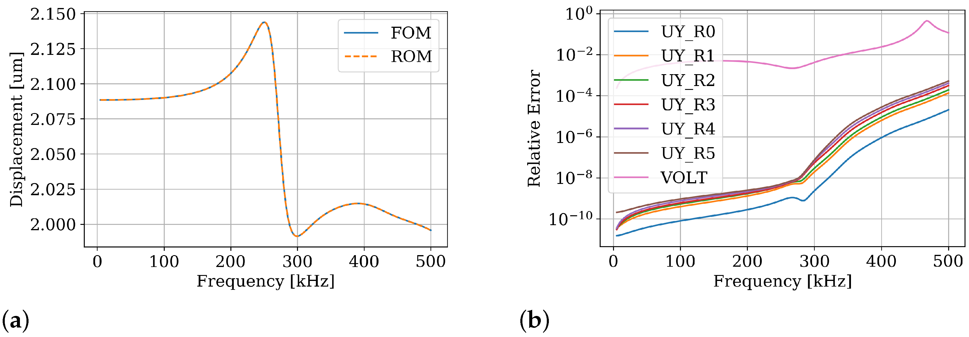
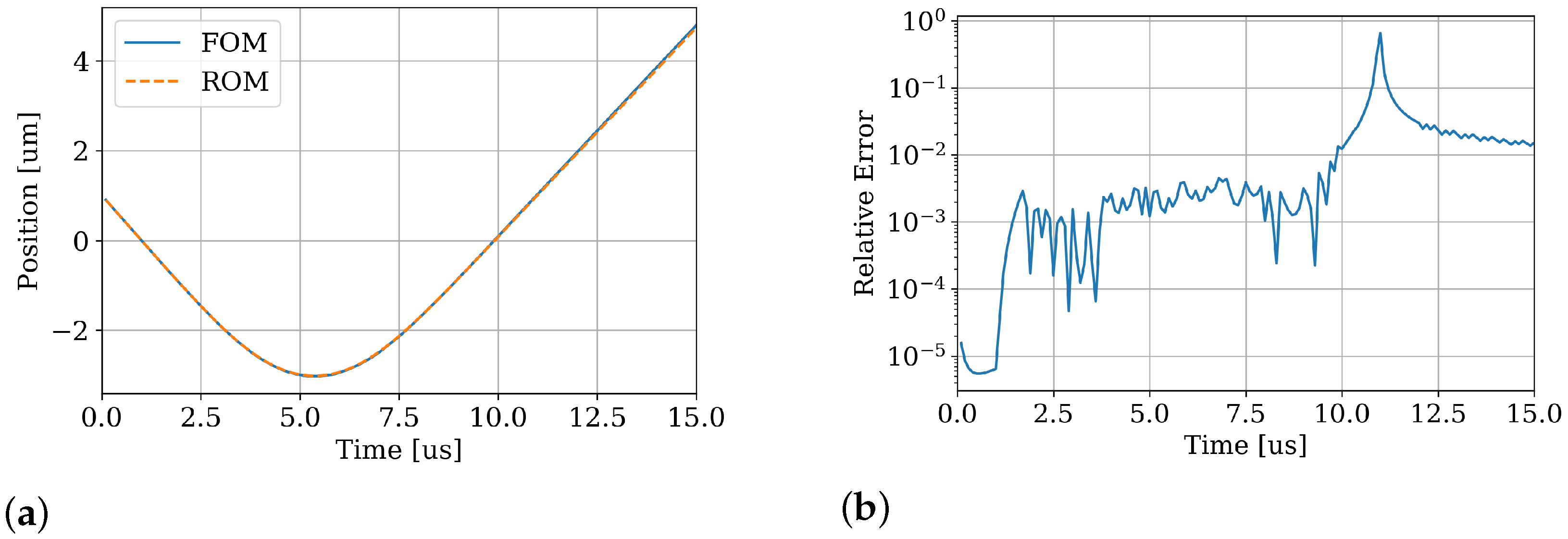
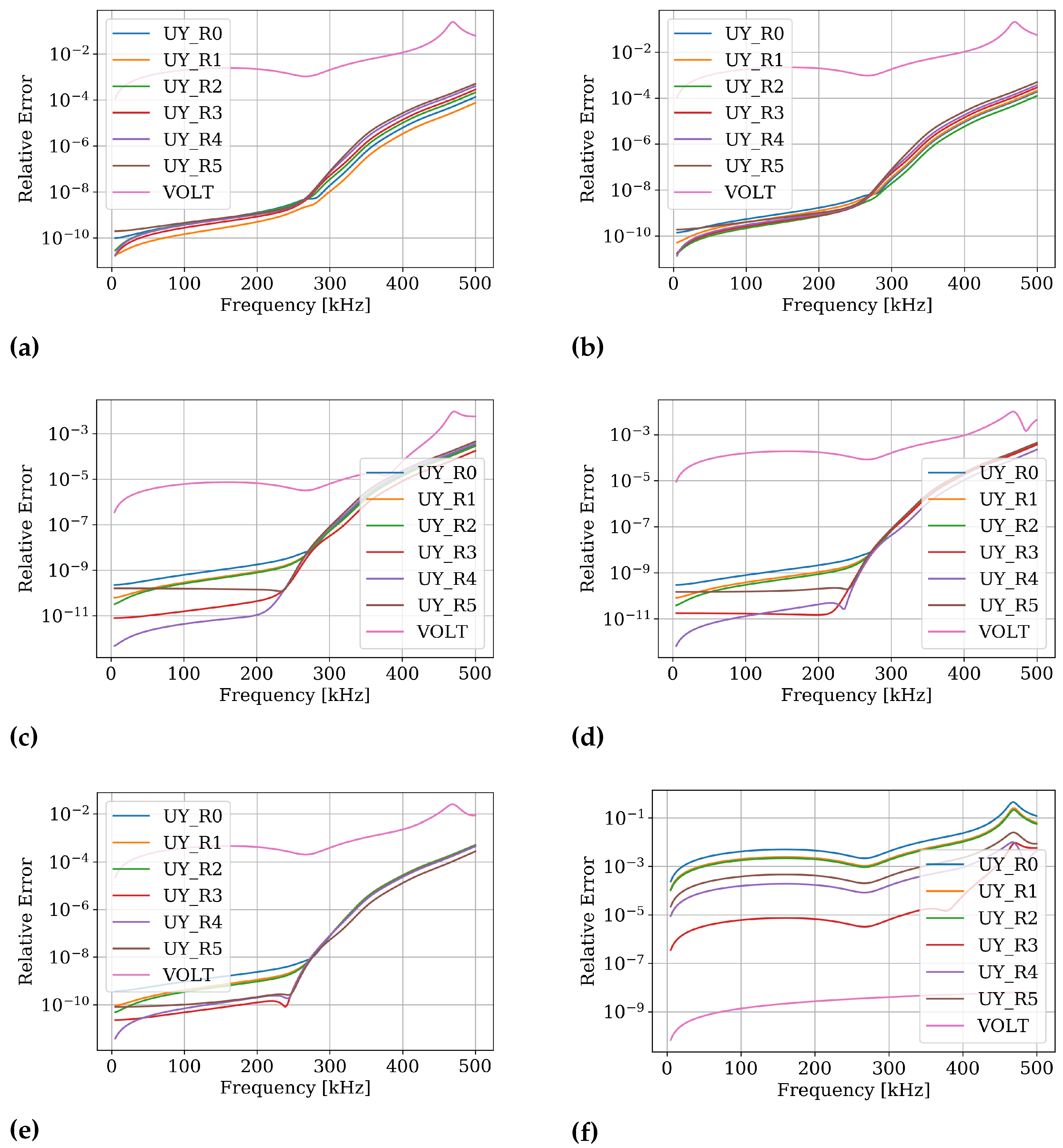
40] can be employed. A further enhancement includes considering the distribution of nonlinear forces in the spatial FE discretization, which improves accuracy. The resulting reduced order model achieves excellent accuracy and decreases the CPU time of transient simulation by several orders of magnitude. In the static comparison in Section 3.2.2, the ROM has a maximal relative error of less than 10 5 with respect to the original finite element model. Such efficient and accurate ROM can be used for optimization of control circuitry. Please note that this methodology is not limited to the kick-actuator considered here, but will perform equally well on similar contact scenarios.
However, our method requires an appropriately designed mesh in the location of impact. Hence, the location must be known in advance and remain constant during impact. Parametric model order reduction would allow dynamical repositioning of the impact location. Further, this work makes use of a rigid body of simple shape. Flexible bodies may be included, but require matching meshes in the contact region. More complex geometries can be handled, but may require preceding simulations to determine the distribution of contact forces. Aside from that, the kick-actuator’s contact only covers imprints of limited depth. This depth can be arbitrarily chosen and deeper impacts would leave the scope of linear elasticity. Therefore, the depth is more a parameter of the model than a limitation. A potential challenge for the proposed method is friction: while Coulomb friction can be introduced easily, more sophisticated friction models remain challenging. In conclusion, this approach is highly advantageous, but is limited to problems of a certain structure.
Future research will aim to extend the method’s scope to more general problems. A combination with parametric MOR seems promising, especially since it is well-suited to linear systems. In the context of the kick-actuator, this extension might allow an unrestricted movement of the sphere. Another goal is to apply the proposed methodology to a different design of the kick-actuator, featuring electrostatic pull-in similar to [20]. Furthermore, experimental investigations are ongoing and comparisons to simulations are planned. The design of the actuator will gradually become more complex to achieve the targeted motion cycle.

Author Contributions

Conceptualization, A.S. and T.B.; methodology, A.S.; software, A.S.; investigation, A.S. and S.M.; writing—original draft preparation, A.S.; writing—review and editing, A.S., S.M., and T.B.; visualization, A.S.; supervision, T.B.; funding acquisition, T.B. All authors have read and agreed to the published version of the manuscript.

Funding

This research was funded by Deutsche Forschungsgemeinschaft (German Research Foundation) grant number 424616052.

Institutional Review Board Statement

Not applicable.

Informed Consent Statement

Not applicable.

Data Availability Statement

The data can be provided by the author A.S. upon reasonable request.

Acknowledgments

We thank Thorlabs GmbH for supplying additional information and their kind permission to use pictures from their website.

Conflicts of Interest

The authors declare no conflict of interest. The funders had no role in the design of the study; in the collection, analyses, or interpretation of data; in the writing of the manuscript, or in the decision to publish the results.

Abbreviations

The following abbreviations are used in this manuscript:
DEIMdiscrete empirical interpolation method
DOFdegree of freedom
ECequivalent circuit
ECSWenergy conserving mesh sampling and weighting
FEfinite element
FEMfinite element method
FOMfull order model
LiDARlight detection and ranging
MORmodel order reduction
ODEordinary differential equation
PDEpartial differential equation
pMORparametric model order reduction
PODproper orthogonal decomposition
PZTlead zirconate titanate
ROMreduced order model

Appendix A. Material Data

Appendix A.1. Electromagnetic Material Properties

Table A1. Data for the linear materials used in the FE model of the catch actuator. μ r e l is the relative permeability, B r the remanence, and H c the coercivity.
Material μ rel [-] B r [ T ] H c [ A m ]Component
Ferrite 1.0611 0.2 150 , 000 Ring magnet, sphere
Copper [50]1--Coils
Air [50]1--Region

Appendix A.2. THP51

The numerical experiments in study deployed the piezoelectric chip actuator PA3JEAW by Thorlabs GmbH. This actuator is made of THP51, a soft piezoelectric ceramic based on PZT [42]. THP51 is an orthotropic material and has a density of ρ = 7700 k g m 3 . Its stiffness matrix C E for no or constant electric field is given by
C E = 158.9 113.0 158.9 sym . 117.1 117.1 144.2 0 0 0 14.08 0 0 0 0 14.08 0 0 0 0 0 22.94 G Pa ,
Its piezoelectric coupling matrix in stress-charge form e by
e = 0 0 0 0 13.38 0 0 0 0 13.38 0 0 3.914 3.914 27.50 0 0 0 C / m 2 ,
And its relative electric permittivity ε T ε by
ε T ε = 3370 0 0 0 3370 0 0 0 3300 .
All material data represent average values and may deviate slightly due to their manufacturing process.

Appendix B. Additional Harmonic Evaluations of the ROM

The system of the linear kick-actuator without contact includes seven inputs and seven outputs. Therefore, to assess the ROM’s accuracy with respect to the FOM’s solutions, each output has to be evaluated for each input. The relative errors of all outputs for a unit load in the first input are shown in Figure 7b. The following six plots present the relative errors of all outputs for each of the remaining inputs.
Figure A1. Harmonic relative error of each of the ROM’s outputs for a single input each. (a) Unit force at R 1 (b) Unit force at R 2 (c) Unit force at R 3 (d) Unit force at R 4 (e) Unit force at R 5 (f) Unit charge at the anode.
Actuators 10 00279 g0a1

References

  1. Chen, M.; Yu, H.; Guo, S.; Xu, R.; Shen, W. An electromagnetically-driven MEMS micromirror for laser projection. In Proceedings of the 10th IEEE International Conference on Nano/Micro Engineered and Molecular Systems, Xi’an, China, 7–11 April 2015; pp. 605–607. [Google Scholar] [CrossRef]
  2. Fan, K.C.; Lin, W.L.; Chiang, L.H.; Chen, S.H.; Chung, T.T.; Yang, Y.J. A 2 × 2 Mechanical Optical Switch With a Thin MEMS Mirror. J. Light. Technol. 2009, 27, 1155–1161. [Google Scholar] [CrossRef]
  3. Hung, A.C.L.; Lai, H.Y.H.; Lin, T.W.; Fu, S.G.; Lu, M.S.C. An electrostatically driven 2D micro-scanning mirror with capacitive sensing for projection display. Sens. Actuators A Phys. 2015, 222, 122–129. [Google Scholar] [CrossRef]
  4. Cho, A.R.; Han, A.; Ju, S.; Jeong, H.; Park, J.H.; Kim, I.; Bu, J.U.; Ji, C.H. Electromagnetic biaxial microscanner with mechanical amplification at resonance. Opt. Express 2015, 23, 16792–16802. [Google Scholar] [CrossRef]
  5. Yalcinkaya, A.D.; Urey, H.; Brown, D.; Montague, T.; Sprague, R. Two-Axis Electromagnetic Microscanner for High Resolution Displays. J. Microelectromech. Syst. 2006, 15, 786–794. [Google Scholar] [CrossRef]
  6. Seo, Y.H.; Hwang, K.; Kim, H.; Jeong, K.H. Scanning MEMS Mirror for High Definition and High Frame Rate Lissajous Patterns. Micromachines 2019, 10, 67. [Google Scholar] [CrossRef] [Green Version]
  7. Ju, S.; Jeong, H.; Park, J.H.; Bu, J.U.; Ji, C.H. Electromagnetic 2D Scanning Micromirror for High Definition Laser Projection Displays. IEEE Photonics Technol. Lett. 2018, 30, 2072–2075. [Google Scholar] [CrossRef]
  8. Hwang, K.; Seo, Y.H.; Jeong, K.H. Microscanners for optical endomicroscopic applications. Micro Nano Syst. Lett. 2017, 5, 1. [Google Scholar] [CrossRef] [Green Version]
  9. Seo, Y.H.; Hwang, K.; Jeong, K.H. 1.65 mm diameter forward-viewing confocal endomicroscopic catheter using a flip-chip bonded electrothermal MEMS fiber scanner. Opt. Express 2018, 26, 4780–4785. [Google Scholar] [CrossRef] [PubMed]
  10. Hu, Q.; Pedersen, C.; Rodrigo, P.J. Eye-safe diode laser Doppler lidar with a MEMS beam-scanner. Opt. Express 2016, 24, 1934–1942. [Google Scholar] [CrossRef] [Green Version]
  11. Kim, J.H.; Lee, S.W.; Jeong, H.S.; Lee, S.K.; Ji, C.H.; Park, J.H. Electromagnetically actuated 2-axis scanning micromirror with large aperture and tilting angle for lidar applications. In Proceedings of the 2015 Transducers—2015 18th International Conference on Solid-State Sensors, Actuators and Microsystems (TRANSDUCERS), Anchorage, AK, USA, 21–25 June 2015; pp. 839–842. [Google Scholar] [CrossRef]
  12. Royo, S.; Ballesta-Garcia, M. An Overview of Lidar Imaging Systems for Autonomous Vehicles. Appl. Sci. 2019, 9, 4093. [Google Scholar] [CrossRef] [Green Version]
  13. Wang, D.; Watkins, C.; Xie, H. MEMS Mirrors for LiDAR: A review. Micromachines 2020, 11, 456. [Google Scholar] [CrossRef]
  14. Gu-Stoppel, S.; Giese, T.; Quenzer, H.J.; Hofmann, U.; Benecke, W. PZT-Actuated and -Sensed Resonant Micromirrors with Large Scan Angles Applying Mechanical Leverage Amplification for Biaxial Scanning. Micromachines 2017, 8, 215. [Google Scholar] [CrossRef] [PubMed] [Green Version]
  15. Ou, C.H.; Lin, Y.C.; Keikoin, Y.; Ono, T.; Esashi, M.; Tsai, Y.C. Two-dimensional MEMS Fe-based metallic glass micromirror driven by an electromagnetic actuator. Jpn. J. Appl. Phys. 2019, 58, SDDL01. [Google Scholar] [CrossRef]
  16. Park, Y.; Moon, S.; Lee, J.; Kim, K.; Lee, S.J.; Lee, J.H. Gimbal-Less Two-Axis Electromagnetic Microscanner with Twist Mechanism. Micromachines 2018, 9, 219. [Google Scholar] [CrossRef] [Green Version]
  17. Jia, K.; Pal, S.; Xie, H. An Electrothermal Tip–Tilt–Piston Micromirror Based on Folded Dual S-Shaped Bimorphs. J. Microelectromech. Syst. 2009, 18, 1004–1015. [Google Scholar] [CrossRef]
  18. Lara-Castro, M.; Herrera-Amaya, A.; Escarola-Rosas, M.A.; Vázquez-Toledo, M.; López-Huerta, F.; Aguilera-Cortés, L.A.; Herrera-May, A.L. Design and Modeling of Polysilicon Electrothermal Actuators for a MEMS Mirror with Low Power Consumption. Micromachines 2017, 8, 203. [Google Scholar] [CrossRef] [Green Version]
  19. Markweg, E.; Nguyen, T.T.; Weinberger, S.; Ament, C.; Hoffmann, M. Development of a Miniaturized Multisensory Positioning Device for Laser Dicing Technology. Phys. Procedia 2011, 12, 387–395. [Google Scholar] [CrossRef] [Green Version]
  20. Bunge, F.; Leopold, S.; Bohm, S.; Hoffmann, M. Scanning micromirror for large, quasi-static 2D-deflections based on electrostatic driven rotation of a hemisphere. Sens. Actuators A Phys. 2016, 243, 159–166. [Google Scholar] [CrossRef]
  21. DFG. Kick and Catch—Cooperative Microactuators for Freely Moving Platforms: SPP 2206: Cooperative Multilevel Multistable Micro Actuator Systems (KOMMMA), 2019. Available online: https://gepris.dfg.de/gepris/projekt/424616052 (accessed on 16 June 2021).
  22. Olbrich, M.; Schütz, A.; Kanjilal, K.; Bechtold, T.; Wallrabe, U.; Ament, C. Co-Design and Control of a Magnetic Microactuator for Freely Moving Platforms. Proceedings of 1st International Electronic Conference on Actuator Technology: Materials, Devices and Applications, Online, 23–27 November 2020; p. 8494. [Google Scholar] [CrossRef]
  23. Schütz, A.; Hu, S.; Rudnyi, E.B.; Bechtold, T. Electromagnetic System-Level Model of Novel Free Flight Microactuator. In Proceedings of the 2020 21st International Conference on Thermal, Mechanical and Multi-Physics Simulation and Experiments in Microelectronics and Microsystems (EuroSimE), Online, 6–27 July 2020; pp. 1–6. [Google Scholar] [CrossRef]
  24. Schütz, A.; Olbrich, M.; Hu, S.; Ament, C.; Bechtold, T. Parametric system-level models for position-control of novel electromagnetic free flight microactuator. Microelectron. Reliab. 2021, 119, 114062. [Google Scholar] [CrossRef]
  25. Antoulas, A.C. Approximation of Large-Scale Dynamical Systems; Advances in design and control; Society for Industrial and Applied Mathematics: Philadelphia, PA, USA, 2005. [Google Scholar] [CrossRef]
  26. Rudnyi, E.B. MOR for ANSYS. In System-Level Modeling of MEMS; Bechtold, T., Schrag, G., Feng, L., Eds.; Advanced Micro and Nanosystems; Wiley-VCH-Verl.: Weinheim, Germany, 2013; pp. 425–438. [Google Scholar]
  27. Balajewicz, M.; Amsallem, D.; Farhat, C. Projection-based model reduction for contact problems. Int. J. Numer. Methods Eng. 2016, 106, 644–663. [Google Scholar] [CrossRef] [Green Version]
  28. Nasdala, L. (Ed.) Kontakt. In FEM-Formelsammlung Statik und Dynamik; Springer Fachmedien Wiesbaden: Wiesbaden, Germany, 2015; pp. 227–244. [Google Scholar] [CrossRef]
  29. Rutzmoser, J. Model Order Reduction for Nonlinear Structural Dynamics: Simulation-Free Approaches. Ph.D. Thesis, Technische Universität München, Garching, Germany, 2018. [Google Scholar]
  30. Carlberg, K.; Bou-Mosleh, C.; Farhat, C. Efficient non-linear model reduction via a least-squares Petrov-Galerkin projection and compressive tensor approximations. Int. J. Numer. Methods Eng. 2011, 86, 155–181. [Google Scholar] [CrossRef]
  31. Goury, O.; Duriez, C. Fast, Generic, and Reliable Control and Simulation of Soft Robots Using Model Order Reduction. IEEE Trans. Robot. 2018, 34, 1565–1576. [Google Scholar] [CrossRef] [Green Version]
  32. Fauque, J.; Ramière, I.; Ryckelynck, D. Hybrid hyper-reduced modeling for contact mechanics problems. Int. J. Numer. Methods Eng. 2018, 115, 117–139. [Google Scholar] [CrossRef]
  33. Tiso, P.; Rixen, D.J. Reduction methods for MEMS nonlinear dynamic analysis. In Nonlinear Modeling and Applications; Proulx, T., Ed.; Conference Proceedings of the Society for Experimental Mechanics Series; Springer: New York, NY, USA, 2011; Volume 2, pp. 53–65. [Google Scholar] [CrossRef]
  34. Idelsohn, S.R.; Cardona, A. A reduction method for nonlinear structural dynamic analysis. Comput. Methods Appl. Mech. Eng. 1985, 49, 253–279. [Google Scholar] [CrossRef]
  35. Manvelyan, D.; Simeon, B.; Wever, U. An Efficient Model Order Reduction Scheme for Dynamic Contact in Linear Elasticity. arXiv 2021, arXiv:2102.03653. [Google Scholar]
  36. Chaturantabut, S.; Sorensen, D.C. Nonlinear Model Reduction via Discrete Empirical Interpolation. SIAM J. Sci. Comput. 2010, 32, 2737–2764. [Google Scholar] [CrossRef]
  37. Farhat, C.; Avery, P.; Chapman, T.; Cortial, J. Dimensional reduction of nonlinear finite element dynamic models with finite rotations and energy-based mesh sampling and weighting for computational efficiency. Int. J. Numer. Methods Eng. 2014, 98, 625–662. [Google Scholar] [CrossRef]
  38. Farhat, C.; Chapman, T.; Avery, P. Structure-preserving, stability, and accuracy properties of the energy-conserving sampling and weighting method for the hyper reduction of nonlinear finite element dynamic models. Int. J. Numer. Methods Eng. 2015, 102, 1077–1110. [Google Scholar] [CrossRef]
  39. Chapman, T. Nonlinear Model Order Reduction for Structural Systems with Contact. Ph.D. Thesis, Stanford University, Stanford, CA, USA, 2019. [Google Scholar]
  40. Del Tin, L. Reduced-Order Modelling, Circuit-Level Design and SOI Fabrication of Microelectromechanical Resonators. Ph.D. Thesis, Università di Bologna, Bologna, Italy, 2007. [CrossRef]
  41. Freund, R.W. Krylov-subspace methods for reduced-order modeling in circuit simulation. J. Comput. Appl. Math. 2000, 123, 395–421. [Google Scholar] [CrossRef] [Green Version]
  42. Thorlabs, Inc. Piezo Actuators, Brochure. Available online: https://www.thorlabs.com/images/Brochures/Thorlabs_Piezo_Brochure.pdf (accessed on 16 June 2021).
  43. Nasdala, L. (Ed.) FEM-Formelsammlung Statik und Dynamik; Springer Fachmedien Wiesbaden: Wiesbaden, Germany, 2015. [Google Scholar] [CrossRef]
  44. Bathe, K.J. Finite Element Procedures, 2nd ed.; Prentice-Hall: Englewood Cliffs, NJ, USA, 2014. [Google Scholar]
  45. Thorlabs, Inc. PA3JEAW-SpecSheet: Piezoelectric Chip, 100 V, 2.2 μm Displacement, 3.0 ×3.0 × 2.0 mm, Pre-Attached Wires. Available online: https://www.thorlabs.com/thorproduct.cfm?partnumber=PA3JEAW (accessed on 16 June 2021).
  46. Bai, Z. Krylov subspace techniques for reduced-order modeling of large-scale dynamical systems. Appl. Numer. Math. 2002, 43, 9–44. [Google Scholar] [CrossRef] [Green Version]
  47. Hu, S.; Yuan, C.; Bechtold, T. Quasi-Schur Transformation for the Stable Compact Modeling of Piezoelectric Energy Harvester Devices. In Proceedings of the 12th International Conference on Scientific Computing in Electrical Engineering, Taormina, Italy, 23–27 September 2018; pp. 267–276. [Google Scholar] [CrossRef]
  48. Yuan, C.; Hu, S.; Castagnotto, A.; Lohmann, B.; Bechtold, T. Implicit Schur Complement for Model Order Reduction of Second Order Piezoelectric Energy Harvester Model. In Proceedings of the 9th Vienna International Conference on Mathematical Modelling (MATHMOD2018), Vienna, Austria, 21–23 February 2018. [Google Scholar] [CrossRef] [Green Version]
  49. Hu, S.; Yuan, C.; Castagnotto, A.; Lohmann, B.; Bouhedma, S.; Hohlfeld, D.; Bechtold, T. Stable reduced order modeling of piezoelectric energy harvesting modules using implicit Schur complement. Microelectron. Reliab. 2018, 85, 148–155. [Google Scholar] [CrossRef]
  50. Ansys®. Academic Research Electromagnetics Suite, Release 2020 R2, Canonsburg, PA, USA, 2020. Available online: https://www.ansys.com/products/release-highlights (accessed on 20 October 2021).
Figure 1. Working principle of the kick and catch actuator system: the kick-actuator launches the hemispherical micromirror into a flight phase. Subsequently, the electromagnetic catch-actuator controls the mirror’s flight. Finally, the catch-actuator decelerates the sphere and supports its smooth landing on the kick-actuator. This sequence achieves a small rotation of the hemisphere and may be repeated periodically to achieve large deflections. Please note the symbolic nature of this illustration. Later versions of the catch-actuator may, for example, contain a three-dimensional Helmholtz-coil configuration. Furthermore, this work focuses on further developing and applying the mathematical methodology of model order reduction (MOR). For this reason, the system is simplified to vertical motion.
Actuators 10 00279 g001
Figure 2. Sectional three-dimensional view of the simplified actuator system with labeled components. This setup deploys a piezoelectric chip actuator for kick-actuation and an assembly of two coils and a ring magnet for electromagnetic interaction. Additionally, the micromirror is included as a magnetic sphere. The setup is designed for preliminary studies. This basis will be extended by more complex assemblies to precisely manipulate the micromirror.
Actuators 10 00279 g002
Figure 3. Considerations for the FEM model of the piezoelectric kick-actuator: (a) Symmetry allows to simulate only one quarter of the model, saving computational effort. (b) A mapped mesh of concentric circles around the location of contact results in equal vertical nodal forces per ring. The center node and the five rings are enumerated from R 0 to R 5 . (c) Contact-induced forces on the kick-actuator are equal per ring. Black arrows indicate the vertical force distribution for a single ring. Separately modelling the sphere and the kick-actuator provides access to the MOR methodology proposed in [40].
Actuators 10 00279 g003
Figure 4. Schematic workflow of MOR, illustrated for the Thorlabs PA3JEAW piezoelectric chip actuator: first, a physical problem to be investigated is chosen and subsequently modeled based on the FEM. The FEM spatially discretizes the computational domain, creating a large set of ODEs. MOR projects these ODEs onto a low-dimensional subspace, reducing the number of equations by several orders of magnitude. Finally, the resulting ROM is ready to use for commercial system-level simulation software. The picture of the actuator is adapted from [45] with the friendly permission of Thorlabs GmbH.
Actuators 10 00279 g004
Figure 5. Schematic diagram of the kick and catch actuator system at system-level, extended by a PID-based position control of the sphere. The four grey areas indicate the system’s major components: the controller, the electromagnetic catch-actuator, the piezoelectric kick-actuator, and the sphere (clockwise from top left). The catch-actuator is modelled as an equivalent circuit, the kick-actuator as an ROM and the micromirror as a point mass.
Actuators 10 00279 g005
Figure 6. The vertical electromagnetic force acting on the spherical magnet, plotted over its position. Each combination of coil currents is shown as a single line. The catch-actuator’s vertical symmetry induces a symmetric force for equal but opposed currents.
Actuators 10 00279 g006
Figure 7. (a) Comparison of the center node’s harmonic displacement amplitude obtained by the original FEM model and the ROM in a frequency range of 0 kHz to 500 kHz. (b) The harmonic relative error of the ROM’s solution for all seven outputs, demonstrating its accuracy. The ROM approximates the original transfer function at an expansion point of 0 Hz. Consequently, all errors are the lowest at this frequency and increase with higher frequencies. Extending the reduced basis with vectors for higher frequencies enhances accuracy if needed. The error plots for the remaining six inputs are provided by Appendix B.
Actuators 10 00279 g007
Figure 8. Static force opposing the sphere’s displacement into the kick-actuator. The sphere starts just in contact with the actuator’s top surface and is displaced 50 μm into the surface in increments of −0.2 μm. (a) Solutions of the reference FEM model and the ROM. Note that the force is one quarter of the full contact force. (b) The ROM’s relative error, demonstrating its accuracy.
Actuators 10 00279 g008
Figure 9. The sphere’s vertical position during impact measured from its lowest point. (a) The solutions of the reference FE model and the ROM. (b) The ROM’s relative error increases in time as deviations accumulate. The sphere leaves contact after 11 μ s , causing a high error at this point in time. Note that, due to limitations of commercial software, different methods are used for time integration.
Actuators 10 00279 g009
Figure 10. The kick and catch actuation at system-level. (a) The sphere’s vertical position over time for the full duration of 5 m s , showing a clear catch at 2.5   m m . (b) Vertical position of the center node for 450 μ s –600 μ s , illustrating the kick actuation.
Actuators 10 00279 g010
Table 1. Dimensions of the catch actutator’s components. H corresponds to a part’s height, R o to the outer radius and R i to the inner radius. The vertical position y refers to center of mass.
ComponentH [mm] R o [mm] R i [mm]y [mm]
Ringmagnet1542.5
Coil22.31.31/4
Sphere-1--
Publisher’s Note: MDPI stays neutral with regard to jurisdictional claims in published maps and institutional affiliations.

