Abstract
This paper presents an automatic optimization method for compliant constant force mechanisms, which eliminates the need for time-consuming parameter tuning and complex model design in the conventional design process. The proposed optimization framework is based on the finite-element analysis (FEA) and multi-objective genetic algorithm (MOGA) methods and is designed in two steps: First, the preliminary mechanism design is carried out to roughly encompass the specified constant force objective; then, the preliminary model is optimized by applying a MOGA based on FEA results. The optimized model can achieve the desired performance automatically while achieving a larger constant force stroke, which is verified by performing FEA simulations and experimental studies. The experimental results demonstrate that the designed CFMs increase the constant force stroke by 16.3% while achieving the specified design accuracy compared to the preliminary prototype.
1. Introduction
Recent decades have seen rapid development of precision manipulation in a variety of new applications [1], including micromanipulation [2], biomedical research [3], precise optics [4], and precision assembly [5]. In addition to guaranteeing precise position control for micro-nano operations, it is required to rigorously regulate the operating force within the appropriate range due to the irregular shape and fragility of micro-scale objects. There are currently two methods to achieve operation precision: force feedback control and mechanism design. Force feedback control regulates the feedback force precisely via the controller, whereas the design of the mechanism modifies the output force by modifying the structural characteristics.
Compared with the complex system and high cost of force feedback control, the mechanism design method is favored by researchers because of its cost-efficiency and simplicity [6,7,8]. In contrast to conventional elastic structures, constant force mechanisms (CFMs) do not adhere to Hooke’s law [9]; Most mechanisms will have quasi-zero stiffness during coupled buckling deformation, allowing CFMs to offer nearly constant force output without feedback within a specific displacement range [10]. Consequently, the applied research on structural damping and static equilibrium of the mechanism has also received attention. Gallego proposed five criteria for the investigation of static equilibrium of compliant mechanisms [11]. On the basis of this criterion, Dunning analyzed the rationality of static equilibration of a six-degree-of-freedom compliant platform with zero stiffness using a stiffness compensation mechanism [12]. Chen proposed a novel concept for designing a fully compliant static balancing mechanism without pre-stressing assembly, thereby eliminating the requirement for pre-stressing assembly of the compliant mechanism [13]. In addition, there are researchers who have utilized CFMs to attain constant torque [14] and gravity balancing [15]. Since the CFMs replace the complex control system with their mechanical characteristics, the compliant constant force mechanisms have garnered a lot of attention for the benefits they offer in terms of significantly reducing the difficulty and complexity of the conventional force feedback control system [16,17,18,19].
The concept of CFMs was extended from the concept of negative stiffness, and early applications were mainly related to rigid bodies [20]. On the basis of the rigid constant force structure, Rahman proposed that the compliant mechanism utilizes the elastic deformation of the flexible parts to realize the constant force mechanism, and introduced a method for designing a constant force compliant mechanism [21]. Guided by this constant-force compliant mechanism design method, Tolman et al. designed a completely flexible constant force mechanism, which used an initial angled parallel guide mechanism, and used FEA and experiments to verify the pseudo-rigid body model for the compliant mechanism [22]. To expand the application scenarios of CFMs, Pardeshi proposed an integral flexible slider-crank mechanism and developed a flexible constant-force mechanism based on bending for geometric amplification of the input motion [23]. In order to overcome the limitation of the traditional inclined beam bistable mechanism, Xu proposed a novel bistable structure based on bevel compound parallel isometric deflection, which has a more compact physical size while maintaining a larger travel in the negative stiffness region [24]. However, this process suffers from the problem that theoretical simulation and finite element analysis are insufficiently comparable. Therefore, Wang and Xu developed a new type of compliant positioning stage with constant force and practically applied to the micromanipulation of biological cells [25,26].
Early studies have found that bending-based CFMs have a significant impact on the safety and reliability of precision operations [27]. In recent years, relevant research has also been conducted on the design and development of compliant constant force microgrippers for precise operations. Liu developed a novel microgripper with passive compliant constant force mechanism to achieve precision manipulation based on a discrete time variable structure control method; the gripper is capable of operating within a 530 μN constant-force range [28]. Zhang designed a unique two-degrees-of-freedom quasi-zero stiffness constant force characteristic to prevent overload during the clamping process [29]. Moreover, Ye proposed a two-stage flexible constant-force microgripper based on the negative stiffness effect in parallel with a two-stage negative stiffness module and a positive stiffness module to produce two different constant force outputs throughout the stroke [30].
In the above design experimental study, since the mechanism design is based on the mechanics theory, problems such as insufficient constant force travel and inconsistency between experiment and theory often occur. Therefore, the constant force mechanism needs to be optimized. Based on FEA, Wu [31] used the multi-objective genetic algorithm (MOGA) to optimize the design variables for a flexible amplification mechanism. To optimize the selected structural parameters under specific displacement conditions to seek the maximum output force, Ding proposed an FEA optimization method based on structural parameters for the problem of insufficient constant force stroke of flexible constant force mechanism [32]. Although the constant force mechanism of the foregoing research can be manually adjusted based on the parameter sensitivity results, the objective function is too singular, which is only the product of the input displacement and the size of constant-force travel, and the optimization objective is ambiguous in [31]; whereas there is only one conceptual optimization objective and so optimization cannot occur for the specified constant force output in [32]. Both are challenging to design structural parameters automatically based on the desired constant force values.
To this end, this paper presents an automatic optimization framework for compliant constant force mechanisms to solve the aforementioned issues. The main contributions are summarized as follows:
- An automatic model-based optimization framework is developed for compliant constant force mechanisms, which can automatically optimize the preliminary structure according to the desired constant force objective;
- The proposed technique reduces the discrepancy between numerical analysis and FEA results while further enhancing the performance of the designed mechanism, hence accelerating the development process of CFMs;
- The experimental results reveal that the proposed method can achieve consistency between the numerical model and the physical prototype, bridging the gap between theory and practical application for the design of compliant constant force mechanisms.
The remainder of the article is structured as follows: Section 2 introduces the preliminary structure design and mathematical model of the compliant constant force mechanism, and the performance of the mechanism is validated using FEA simulation. Section 3 conducts the parameter sensitivity analysis of the designed CFM. The construction of the FEA simulation optimization method is described in Section 4. Prototyping and experimental research of the optimized mechanism are presented in Section 5. Section 6 summarizes this work.
2. Preliminary Model Design
This work begins with the preliminary design of the constant force mechanism based on the stiffness combination principle [33], which is used to construct the optimal structural framework that follows. The stiffness combination principle combines positive and negative stiffness mechanisms to provide quasi-zero stiffness in the designed deformation stroke. The negative stiffness is produced through the bistable beam mechanism, whereas the positive stiffness is provided by the U-shaped structure. The physical model of the constant force mechanism is shown in Figure 1a.

Figure 1.
(a) The compliant constant force mechanism isometric schematic. (b) The sketch of force conditions for a bistable beam. (c) Positive stiffness flexure beam and cross section.
2.1. Design of Negative-Stiffness Mechanism
The fixed guide beam in the bistable beam is symmetrically tilted and arranged, and the buckling effect appears during the bending deformation process, which exhibits bistability characteristics and produces a negative stiffness interval [30,34]. The force condition of a bistable beam can be shown as Figure 1b. The elliptic integral method, one of the most prevalent methods, is employed to numerically analyze the mechanical performance of the bistable beam. Hence, the moment of a beam point can be represented by the Bernoulli-Euler equation:
where E is the Young’s modulus of the beam, is the rotational inertia of the beam. The definition of the inertia I is based on the assumption that the beam has a rectangular cross section. , and are thickness, width, and inclination angle of the beam, respectively. is the force angle with respect to the x-axis. stands for the differential of the length of the beam. a and b represent the coordinates of any point on the beam. a and b are the coordinates along axes x and y, respectively. M and R indicate the torque and force exerted on the beam, respectively.
According to the force conditions depicted in Figure 1b, the following relationship can be derived:
Differentiate Equation (1) with respect to s, and substitute Equation (2) into it
then integrating Equation (3) with respect to , yields
where C represents a constant.
To determine the position of a point on the beam, the following equation is introduced
Eliminate the variable s in Equations (2) and (5) by making use of Equation (4), and the following equations are obtained:
Introduce variable and constant to construct elliptic integral equation [25], which are related by:
After trigonometric transformation and derivative substitution of Equation (9) into Equation (6), we obtain
To simplify the operation, is denoted. Then Equation (10) can be simplified as
Define the left side of the Equation (11) as as the dimensionless reaction force. Thus, Equation (11) can be abbreviated as
where the left side of the equation is the dimensionless reaction force, and the right side of the equation is the elliptic integral of the first kind [35].
According to Equation (9), the trigonometric transformation of Equation (7), and then combined with Equation (10), we can obtain:
The right-hand side of the equation contains elliptic integrals of the first and second kinds; so Equation (13) can be written as
The same can be obtained
where and is the incomplete elliptic integrals of the first and second kind, respectively.
According to Equation (9), considering the boundary condition , the first and second buckling modes of the beam can be obtained
where the first-mode solution describes the flexure deflections with one inflection point, and the second-mode solution describes the deflections with two inflection points [24]. When there is an inflection point of the beam in bending, the angle of a point on the beam with respect to the x-axis is likely to be zero. Therefore, the variables , and R can be derived by solving the governing equation and solving mode.
To sum up, when the variable solution is obtained, the total driving force can be expressed as
Consequently, the relevant parameters of the bistable beam can be computed by solving the above equation.
2.2. Design of Positive-Stiffness Mechanism
In order to counteract the negative stiffness characteristics of the bistable beam, a positive stiffness mechanism is needed to make the mechanism develop quasi-zero stiffness. A U-shaped structure consisting of four fixed-guided flexures was chosen, which would experience the same deformation due to having the same dimensions [36]. Reference [33] has made the derivation of the equivalent stiffness of the positive stiffness mechanism, and the equivalent stiffness can be written in conjunction with Figure 1c as follows:
where E is the Young’s modulus of the material, and , , and represent the thickness, width, and length of the beam, respectively.
2.3. Parameters of Preliminary Model
Since solving the inversion of the equation for bistable beam is extremely complicated, the current design process of constant force mechanisms relies heavily on trial-and-error until suitable structural parameters are determined. Since this is a multi-objective optimization problem, finding the optimal solution manually is challenging and time-consuming. Therefore, an arbitrary set of parameters surrounding the desired performance domain is first determined to create a preliminary model based on the developed method in this work. The parameters of the designed CFMs are shown as Table 1.

Table 1.
Parameters of the preliminary constant force mechanism.
The preliminary model is investigated using a mathematical model, finite element analysis, and experimental verification; the results are depicted in Figure 2. It can be seen that the mathematical results yield a larger constant force value of N, while the FEA results produce a constant force of N, a reduction of 17.8% relative to the mathematical results. In contrast to the assumptions of the mathematical model, the mechanical behavior of 3D-printed ABS plastic is neither linear nor isotropic. This might be the cause of the significant errors in the analytical model. This suggests that, even if the structural parameters corresponding to the desired performance can be obtained by optimization algorithms based on mathematical models, the resultant structural parameters will diverge from the FEA and the experimental results, necessitating another round of trial-and-error parameter tuning based on the FEA model. However, if the structure can be optimized based on FEA results, the final experimental prototype can achieve a similar performance as the design object. The detailed procedure for generating the experimental results will be given in Section 5.
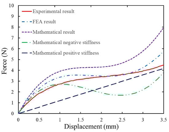
Figure 2.
Comparison of FEA results, mathematical results and experimental results of the preliminary constant force mechanism.
3. Parametric Sensitivity Analysis
In contrast to positive stiffness beams, the properties of negative stiffness beams in an inclined state are extremely sensitive to parameter changes. To better comprehend the impact of parameter variations on the performance of the CFMs, the sensitivity analysis of its main structural parameters should be considered. Despite the large discrepancies between the analytical model and prototype model, the effect of parameter variations on performance follows a consistent pattern, meaning that the trend of the influence of different parameter changes on performance is consistent. In order to facilitate the sensitivity analysis of the primary structural parameters and since the analytical model has lower computation times with respect to the FEA, it is reasonable to utilize the analytical model presented in the preceding subsection to perform the following analysis.
The analyzed parameter settings for the inclination angle, length, thickness, and width of the beam are shown as Table 2. The effects of varying the principal parameters on the negative stiffness mechanism are depicted in Figure 3. The curves of the different colored lines in the figure represent the performance variation of the parameter over a given range through the same interval, the range and interval are given in the legend. Figure 3a illustrates that as the inclination angle increases, the force output also increases, as do the negative stiffness characteristics and the gradient. The effect of length variation is opposite to that of the inclination angle, as shown in Figure 3b, albeit the magnitude is much less sensitive. Figure 3c,d show the influence of the out-of-plane thickness and in-plane width of the bistable beam on the force-displacement relationship. It can be observed that the force grows as both variables increase; however, the negative stiffness characteristic increases as the former variable increases and reduces as the later variable increases. In addition, as the in-plane width grows, the force-displacement characteristic curve fluctuates significantly more than the other parameters. The length has the lowest sensitivity to fluctuations in the force-displacement characteristic curve compared to other parameters. According to Equation (18), the positive stiffness is proportional to the thickness of the beam as well as to the third power of the width, and inversely proportional to the third power of the beam length. In summary, the influence of various structural parameters on the performance is analyzed, and the inclination angle, width and thickness of the negative stiffness beam and the length, width and thickness of the positive stiffness beam are selected as the required optimization structural parameters.
Table 2.
Analysis of structural parameters of bistable beams.
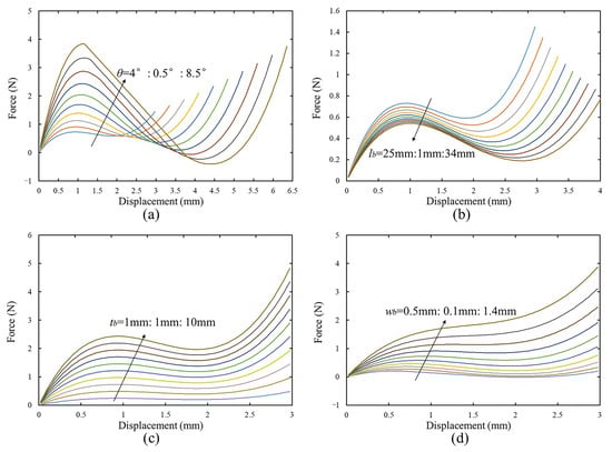
Figure 3.
Simulation result of the force–displacement relationship for bistable beams with varying (a) inclination angle, (b) length, (c) thickness, and (d) width.
4. Mechanism Optimization
The structural optimization of the compliant constant force mechanism is carried out based on FEA results, the multi-objective genetic algorithm (MOGA) is utilized due to its effectiveness to find the global optimal solution. The optimization framework is shown as Figure 4. Particularly, the preliminary structure of the compliant constant force mechanism is designed roughly using a mathematical model, after parameterizing the model according to the principal parameters, the structural parameters are updated using MOGA to find the optimal parameter set according to the designed objective function.
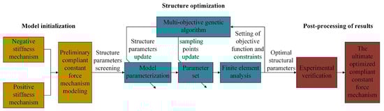
Figure 4.
The optimization framework flow chart.
The software ANSYS Workbench 2020 is utilized for static structural analysis. The force-displacement characteristic curve can be obtained by solving for the changes in force that occur for the corresponding varying displacement using displacement as the simulation input. The degree of displacement is manually adjustable based on the constant force stroke depicted by the corresponding curve. The large deformation of the mechanism is taken into account and the shear deformation effect is not considered. The mesh size is set to 0.5 mm in the simulation, the total number of elements is 40,065, the cell type is tetrahedral, and the degree is linear. However, mesh size has less of an effect on convergence results. The direct optimization module with the integrated MOGA framework of ANSYS Workbench is adopted. The evaluation criteria for the constant force mechanism are constructed based on the desired constant force and FEA result. A computer with an Intel(R) Xeon(R) CPU E5-2673 v4 @ 2.30 GHz and 64 GB RAM is run for approximately 14 days to obtain the final optimization results.
The design objective of the compliant constant force mechanism is generally to achieve the desired constant force output and to have the greatest constant force stroke possible. The optimization problem can be described as follows:
where is the output of CFMs, represents the constant force stroke, is the desired constant force output, w, t, and are the structural parameters to be optimized, in which t and w indicate the thickness and width of the compliant beams, respectively.
Definition 1.
Since FEA results cannot directly produce constant force, the following definition is provided to examine its performance. Constant force output indicates that the force output of a CFM remains approximately constant throughout a specified displacement period. Constant force stroke is the maximum interval within a specified force range.
To construct evaluation metrics for constant force mechanism optimization, the sampling points (, ) are chosen from the force-displacement results of the FEA results, as shown in Figure 5, where represents the displacement input and is the output force at the current displacement point. indicates the number of random points are chosen as optimization indicators during the optimization procedure. In order to achieve a constant force stroke, it is necessary to ensure that any three points measured during the stroke lie on an agreed-upon straight line. Clearly, the greater the number of points, the smaller the error. In addition, the gradient between two selected points is introduced as a criterion for identifying the quasi-zero stiffness stroke. If the gradient between the selected points is always about zero, it assures that the selected points are all in constant force interval. In addition, the total deformation average and equivalent stress maximum are used as auxiliary judging criteria in conjunction with the actual working situation. The maximum TDA and the minimum ESM are usually chosen to make the convergence results closer to reality. The large TDA and small ESM indicate a high degree of deformation resistance and a more compact structure, the calculation fields for each of these indices are on the entire mechanism. The = 2 N and n = 3 are set to make it easier for the FEA optimization to converge in this study. The rules of objective function of the built-in MOGA module in FEA are set as follows:
- The accuracy of the optimized constant force is ±10%;
- Maximize the constant force stroke ;
- Minimize the gradient between the selected points ;
- Maximize the total deformation average (TDA) of the mechanism;
- Minimize the equivalent stress maximum (ESM) of the mechanism.

Figure 5.
Schematic diagram of sampling points.
The positive and negative stiffness beams typically have the same width and thickness in the prototype processing [7,26]. To simplify the optimization conditions, the thickness and width of the positive and negative stiffness beams are set to be identical. The upper and lower bounds of the selected structural parameters are set as follows in the MOGA optimization function module.
The ABS plastic is chosen as the mechanism material to facilitate rapid prototyping. Due to the fact that the structural properties of 3D-printed structures differ from those of pure materials, the ABS mechanical properties utilized in this work are the result of modifications based on the parameters of pure materials and experimental results. Its mechanical properties utilized in the FEA study are listed in Table 3. One sample point is a collection of optimization objectives within a constraint range that the system randomly selects to iterate during the automatic optimization process, remaining until an objective is satisfied. 400 initial sample points are created when the system begins to optimize. The larger the initial number, the faster the convergence, but the greater the computational requirements. A total of 970 sample points is the final number of sample points automatically generated by the optimization algorithm when it converges and stops. The diagram of points sampling is depicted in Figure 6. The optimization system automatically chooses sample points that satisfy the constraints and the objective function. The upper and lower boundaries in the figure represent the maximum and minimum values of optimization parameters and selected objective functions.
Table 3.
Mechanical properties of ABS plastic materials.
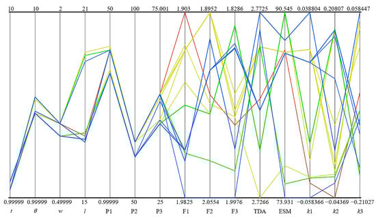
Figure 6.
Design point sampling diagram.
Remark 1.
The compliant mechanism is designed with longitudinal symmetry to better demonstrate its constant force performance in this work. However, the asymmetric mechanism can also be automatically optimized by designing the structural parameters of each side independently as optimization variables.
Different structural parameters exert varying degrees of influence on the objective function; their respective sensitivity relationships are depicted in Figure 7. It is evident that ESM, and is sensitive to t, whereas , TDA and is more sensitive to . In addition, and ESM has a negligible effect on w, whereas is insensitive to . However, the range of influence of the latter two structural parameters is greater than that of the previous two. The columns that do not appear correspondingly in the figure are all zero values. Controlling the variation of different structural parameters can result in a more flexible constant force and stroke. According to the objective function and constraints, the optimal design points can be determined following the simulation optimization method. The final values for the optimized structural parameters are shown in Table 4.
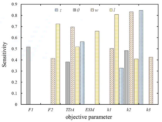
Figure 7.
The sensitivity of optimized structural parameters.
Table 4.
Final optimized structural parameters.
The CFM model is reconstructed based on the optimized structural parameters; its force-displacement characteristic curves from the FEA results prior to and after optimization are depicted in Figure 8. It can be seen that the roughly designed preliminary model can automatically reach the desired constant force output and increase the constant force interval based on the proposed optimization method. Particularly, the preliminary model has a constant force output of N and constant force interval of mm in the range of 0.88 to 2.75 mm; the optimized model shows a constant force output of N and constant force interval of mm in the range of 0.82 to 3.08 mm. The error of constant force output relative to the design objective is 5%, which falls within the error range that was specified. Simultaneously, the constant force interval was increased by 20.9% after the model optimization.
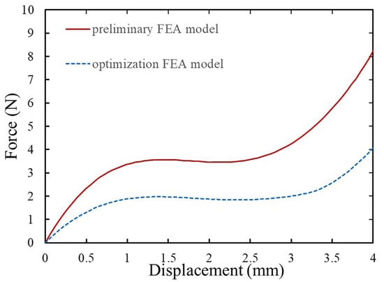
Figure 8.
Comparison between preliminary FEA model and optimized FEA model.
5. Experimental Verification
In this work, the reasonableness of the results after simulation optimization is supported by experiments. And all the results are summarized and compared and analyzed to verify the correctness of the model-based optimization framework.
5.1. Experimental Setup
The preliminary and optimized compliant constant force mechanisms are fabricated by ABS plastic using FDM 3D printing Technology. The comparison of the preliminary and optimized prototypes is shown in Figure 9. The experimental setup, as shown in Figure 10, is constructed to validate the performance improvement based on the proposed optimization method. The fabricated compliant constant force mechanism is mounted on an optical breadboard for adjustment convenience. A personal computer is adopted to process the input and output data based on the real-time controller (model: NI-cRIO 9047), a servo motor stage (model: ASDA-B2) is used to provide driving force on the prototype so that it can reach the desired constant force range, and the force feedback is given by a mounted force sensor (model: FUTEK-lsb201). The displacement input in the experiment is provided by the position control mode of the servo motor.
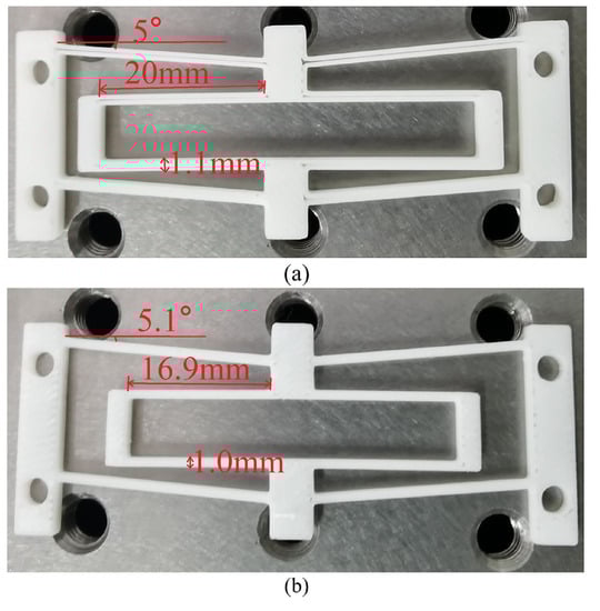
Figure 9.
Comparison of the preliminary and optimized prototype (a) preliminary prototype, (b) optimized prototype.
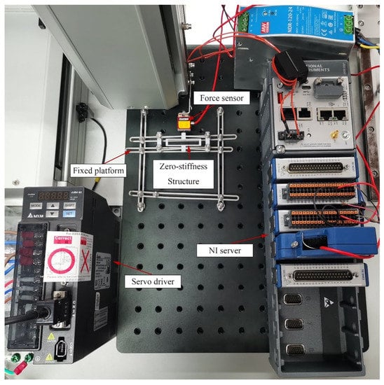
Figure 10.
Experimental setup for the complaint constant force mechanisms.
5.2. Experimental Results
The preliminary prototype and the optimized prototype each performed five times of experimentation, which aimed to generate more reliable experimental data and eliminate experimental errors. The experimental results are shown in Figure 11. The portion of the diagram that is shaded represents the region where the highest and lowest values were obtained from different experiments. The solid and dashed lines represent the mean values of experimental results corresponding to the force-displacement characteristic of the preliminary model and the optimized model, respectively. It can be observed that the output of the optimized prototype exhibits consistent performance across experiments.
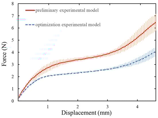
Figure 11.
Comparison of the results and error intervals between the preliminary and optimized experimental models.
The force-displacement characteristics of the mathematical model, FEA result, and experimental result prior to and after optimization are combined together for better data analysis, as shown in Figure 12. The preliminary mathematical model is designed roughly with a constant force output of N based on the proposed automatic optimization method for compliant constant force mechanisms, while the design objective is 2 N, which is a relatively lenient condition, i.e., the performance of the preliminary model can vary considerably from the desired objective. The constant force output of the FEA result and the fabricated prototype, according to the designed preliminary parameters, is N and N, respectively. However, the optimized model has a constant force output of N in the FEA result and N in the prototype testing based on the proposed optimization method, which is within the 10% error range specified by the design objective. Errors may be caused by displacement deviations resulting from driving force and fabrication precision in 3D printing. These are expected to be enhanced by more precise test environments and fabrication techniques. This verifies the practicability of the proposed FEA-based optimization method.
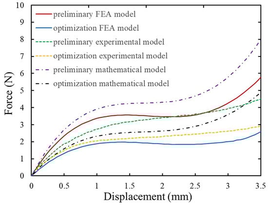
Figure 12.
The experimental results, mathematical results and FEA results in the preliminary model and the optimized model are compared.
Moreover, the experimental results of the preliminary model indicate a constant force stroke of 1350 μm with a range of 1.33 to 2.68 mm. The experimental results of the optimized model have a constant force stroke of 1570 μm, ranging from 0.88 to 2.45 mm. The optimized prototype exhibits a 16.30% increase in constant force stroke compared to the preliminary prototype. It is capable of demonstrating that the proposed optimization method increases the constant force stroke at the same time.
6. Conclusions
In this work, a novel automatic optimization method has been proposed for compliant constant force mechanisms. The proposed method can automatically ensure that the CFMs output the desired constant force based on the FEA and MOGA methods. The resultant complex design of constant force mechanisms becomes designing a preliminary model to roughly encompass the desired objective. This makes it possible to eliminate the need for time-consuming parameter tuning and complex model design in the conventional design process of CFMs while achieving a larger constant force stroke. Experimental and FEA results prove the validity of the proposed method. The proposed model-based design framework is applicable to other types of CFMs with specific constant force outputs due to the applicability of the finite element analysis optimization method. It can also be utilized to determine how to obtain optimal performance from compliant mechanisms based on structural parameters and constant force output. Future research could discretize the differential equations of the beam and develop a finite element analysis employing solely beam elements to validate the mathematical model. In addition, additional criteria, such as the bistable beam length, can be optimized as constraints, and the adequacy of the parameter range can be further discussed. The current evaluation criteria utilizes numerical derivatives, which can result in substantial inaccuracies and necessitates additional validation probes. Furthermore, the development of practical applications such as compliant constant force micro-grippers with a focus on the optimized compliant constant force mechanism can also be a future topic based on the proposed automatic optimization method.
Author Contributions
Conceptualization, Z.T. and G.W.; methodology, Z.T. and G.W.; software, Z.T. and X.Z.; validation, Z.T.; formal analysis, Z.T. and G.W.; investigation, Z.T. and G.W.; resources, G.W.; data curation, Z.T.; writing—original draft preparation, Z.T.; writing—review and editing, G.W. and X.Z.; visualization, Z.T., G.W. and X.Z.; supervision, G.W.; project administration, G.W.; funding acquisition, G.W. All authors have read and agreed to the published version of the manuscript.
Funding
This research was funded by the National Natural Science Foundation of China under Grant 52265070 and Guizhou Provincial Science and Technology Projects under Grant [2020]1Y233.
Institutional Review Board Statement
Not applicable.
Informed Consent Statement
Not applicable.
Data Availability Statement
Not applicable.
Conflicts of Interest
The authors declare no conflict of interest.
References
- Li, C.; Gu, X.; Xiao, X.; Lim, C.M.; Ren, H. Compliant and Flexible Robotic System with Parallel Continuum Mechanism for Transoral Surgery: A Pilot Cadaveric Study. Robotics 2022, 11, 135. [Google Scholar] [CrossRef]
- Leveziel, M.; Haouas, W.; Laurent, G.J.; Gauthier, M.; Dahmouche, R. MiGriBot: A miniature parallel robot with integrated gripping for high-throughput micromanipulation. Sci. Robot. 2022, 7, eabn4292. [Google Scholar] [CrossRef] [PubMed]
- Wang, G.; Xu, Q. Design and precision position/force control of a piezo-driven microinjection system. IEEE/ASME Trans. Mechatronics 2017, 22, 1744–1754. [Google Scholar] [CrossRef]
- Lyu, Z.; Xu, Q. Design and testing of a new piezoelectric-actuated symmetric compliant microgripper. Actuators 2022, 11, 77. [Google Scholar] [CrossRef]
- Liu, S.; Li, Y.F.; Xing, D. Sensing and control for simultaneous precision peg-in-hole assembly of multiple objects. IEEE Trans. Autom. Sci. Eng. 2019, 17, 310–324. [Google Scholar] [CrossRef]
- Veroli, A.; Buzzin, A.; Frezza, F.; De Cesare, G.; Hamidullah, M.; Giovine, E.; Verotti, M.; Belfiore, N.P. An Approach to the Extreme Miniaturization of Rotary Comb Drives. Actuators 2018, 7, 70. [Google Scholar] [CrossRef]
- Zhang, X.; Wang, G.; Xu, Q. Design, Analysis and Testing of a New Compliant Compound Constant-Force Mechanism. Actuators 2018, 7, 65. [Google Scholar] [CrossRef]
- Liu, T.; Hao, G. Design of a Cylindrical Compliant Linear Guide with Decoupling Parallelogram Mechanisms. Micromachines 2022, 13, 1275. [Google Scholar] [CrossRef]
- Howell, L.L. Compliant Mechanisms. In 21st Century Kinematics; Springer: London, UK, 2013; pp. 189–216. [Google Scholar]
- Wang, D.A.; Chen, J.H.; Pham, H.T. A Constant-Force Bistable Micromechanism. Sens. Actuators A Phys. 2013, 189, 481–487. [Google Scholar] [CrossRef]
- Gallego, J.A.; Herder, J.L. Criteria for the Static Balancing of Compliant Mechanisms. In Proceedings of the ASME Design Engineering Technical Conference, Montreal, QC, Canada, 15–18 August 2010; pp. 465–473. [Google Scholar]
- Dunning, A.G.; Tolou, N.; Herder, J.L. Review Article: Inventory of platforms towards the design of a statically balanced six degrees of freedom compliant precision stage. Mech. Sci. 2011, 2, 157–168. [Google Scholar] [CrossRef]
- Chen, G.; Zhang, S. Fully-compliant statically-balanced mechanisms without prestressing assembly: Concepts and case studies. Mech. Sci. 2011, 2, 169–174. [Google Scholar] [CrossRef]
- Hou, C.W.; Lan, C.C. Functional joint mechanisms with constant-torque outputs. Mech. Mach. Theory 2013, 62, 166–181. [Google Scholar] [CrossRef]
- Radaelli, G.; Herder, J.L. A monolithic compliant large-range gravity balancer. Mech. Mach. Theory 2016, 102, 55–67. [Google Scholar] [CrossRef]
- Wang, P.; Xu, Q. Design and Modeling of Constant-Force Mechanisms: A Survey. Mech. Mach. Theory 2018, 119, 1–21. [Google Scholar] [CrossRef]
- Mottola, G.; Cocconcelli, M.; Rubini, R.; Carricato, M. Gravity Balancing of Parallel Robots by Constant-Force Generators. In Gravity Compensation in Robotics; Springer International Publishing: Cham, Switzerland, 2022; pp. 229–273. [Google Scholar]
- Wei, Y.; Xu, Q. Design of a new passive end-effector based on constant-force mechanism for robotic polishing. Robot. Comput.-Integr. Manuf. 2022, 74, 102278. [Google Scholar] [CrossRef]
- Zhang, Q.; Yan, P.; Wang, H. A curved-beam based quasi-constant force mechanism supporting large range and force-sensitive robotic manipulation. Mech. Mach. Theory 2022, 172, 104799. [Google Scholar] [CrossRef]
- van Eijk, J.; Dijksman, J. Plate spring mechanism with constant negative stiffness. Mech. Mach. Theory 1979, 14, 1–9. [Google Scholar] [CrossRef]
- Rahman, M.U. Design of Constant Force Compliant Mechanisms. Ph.D. Thesis, Texas A&M University-Kingsville, Kingsville, TX, USA, 2014. [Google Scholar]
- Tolman, K.A.; Merriam, E.G.; Howell, L.L. Compliant Constant-Force Linear-Motion Mechanism. Mech. Mach. Theory 2016, 106, 68–79. [Google Scholar] [CrossRef]
- Pardeshi, S.; Kandharkar, S.; Deshmukh, B. Monolithic Compliant Slider Crank Mechanism for Motion Amplification. Mater. Today Proc. 2017, 4, 1677–1682. [Google Scholar] [CrossRef]
- Xu, Q. Design of a Large-Stroke Bistable Mechanism for the Application in Constant-Force Micropositioning Stage. J. Mech. Robot. 2017, 9, 011006. [Google Scholar] [CrossRef]
- Wang, P.; Xu, Q. Design of a Flexure-Based Constant-Force XY Precision Positioning Stage. Mech. Mach. Theory 2017, 108, 1–13. [Google Scholar] [CrossRef]
- Wang, P.; Xu, Q. Design and Testing of a Flexure-Based Constant-Force Stage for Biological Cell Micromanipulation. IEEE Trans. Autom. Sci. Eng. 2017, 15, 1114–1126. [Google Scholar] [CrossRef]
- Bossert, D.; Ly, U.L.; Vagners, J. Experimental Evaluation of a Hybrid Position and Force Surface Following Algorithm for Unknown Surfaces. In Proceedings of the IEEE International Conference on Robotics and Automation, Minneapolis, MN, USA, 22–28 April 1996; Volume 3, pp. 2252–2257. [Google Scholar]
- Liu, Y.; Zhang, Y.; Xu, Q. Design and Control of a Novel Compliant Constant-Force Gripper Based on Buckled Fixed-Guided Beams. IEEE/ASME Trans. Mechatronics 2016, 22, 476–486. [Google Scholar] [CrossRef]
- Zhang, X.; Xu, Q. Design and Analysis of a Constant-Force Parallel Micro-Gripper. In Proceedings of the 2017 IEEE International Conference on Robotics and Biomimetics (ROBIO), Macau, Macao, 5–8 December 2017; pp. 1112–1117. [Google Scholar]
- Ye, T.; Ling, J.; Kang, X.; Feng, Z.; Xiao, X. A Novel Two-Stage Constant Force Compliant Microgripper. J. Mech. Des. 2021, 143, 053302. [Google Scholar] [CrossRef]
- Wu, Z.; Xu, Q. Design, Fabrication, and Testing of a New Compact Piezo-Driven Flexure Stage for Vertical Micro/Nanopositioning. IEEE Trans. Autom. Sci. Eng. 2018, 16, 908–918. [Google Scholar] [CrossRef]
- Ding, B.; Li, X.; Li, Y. FEA-based Optimization and Experimental Verification of a Typical Flexure-Based Constant Force Module. Sens. Actuators A Phys. 2021, 332, 113083. [Google Scholar] [CrossRef]
- Xu, Q. New Flexure Parallel-Kinematic Micropositioning System with Large Workspace. IEEE Trans. Robot. 2011, 28, 478–491. [Google Scholar] [CrossRef]
- Ma, F.; Chen, G. Bi-BCM: A Closed-Form Solution for Fixed-Guided Beams in Compliant Mechanisms. J. Mech. Robot. 2017, 9, 59063. [Google Scholar] [CrossRef]
- Jensen, B.D.; Hoist, G.L.; Teichert, G.H. Modeling and Experiments of Buckling Modes and Deflection of Fixed-Guided Beams in Compliant Mechanisms. J. Mech. Des. 2011, 133, 051002. [Google Scholar]
- Xu, Q. A Novel Compliant Micropositioning Stage with Dual Ranges and Resolutions. Sens. Actuators A Phys. 2014, 205, 6–14. [Google Scholar] [CrossRef]
Disclaimer/Publisher’s Note: The statements, opinions and data contained in all publications are solely those of the individual author(s) and contributor(s) and not of MDPI and/or the editor(s). MDPI and/or the editor(s) disclaim responsibility for any injury to people or property resulting from any ideas, methods, instructions or products referred to in the content. |
© 2023 by the authors. Licensee MDPI, Basel, Switzerland. This article is an open access article distributed under the terms and conditions of the Creative Commons Attribution (CC BY) license (https://creativecommons.org/licenses/by/4.0/).