Article

Mechanical Design and Experiments of a New Rotational Variable Stiffness Actuator for Hybrid Passive–Active Stiffness Regulation

1
College of Mechanical and Electrical Engineering, Zhengzhou University of Light Industry, Zhengzhou 450001, China
2
Henan Provincial Key Laboratory of Intelligent Manufacturing of Mechanical Equipment, Zhengzhou 450001, China
*
Author to whom correspondence should be addressed.
Actuators 2023, 12(12), 450; https://doi.org/10.3390/act12120450
Submission received: 29 October 2023 / Revised: 29 November 2023 / Accepted: 1 December 2023 / Published: 4 December 2023
(This article belongs to the Section Actuators for Robotics)

Abstract

:
To improve collision safety in robot–human collaborative applications, increasing attention has been paid to rotational variable stiffness actuators. A new rotational variable stiffness actuator, which works in two stages, is proposed for hybrid passive–active stiffness regulation. The passive stage is based on the motions of springs driven by the rack-and-pinion systems, elastically converting the shaft’s rotation into the inner shell rotation fixed to the internal gear of the active stage. The active stage is designed to achieve the movement of the pivot point located on the roller actuated by the adjustment motor, providing the output angle of the output shaft. The two pairs of rack-and-pinion systems of the passive stage and the two pairs of planetary gears of the active stage are designed for side-by-side placement, improving the stability and balance of the stiffness regulation process. Two symmetrical cam-slider mechanisms acting as leverage pivots ensure the synchronous movements of the two rollers. The variable stiffness actuator is designed and validated by simulations and experiments. Strength analysis and stiffness analysis are presented. The designed actuator can obtain the range of stiffness adjustment of 35–3286 N·mm/deg. The range of the angle difference between the input and output shafts is ±48°.

1. Introduction

Robots are widely used in human–machine cooperation, such as surgery and service. The demand for additional work to protect workers from hazards of robot–human collisions, reduce the risk, and improve the intelligence of such robots is increasing [1]. Robots’ flexibility requires improvement [2,3,4] to increase safety and cooperation performance [5,6]. Therefore, the flexible joint based on a variable stiffness actuator is considered an important strategy, becoming the focus of the relevant research. The variable stiffness actuators include linear [7,8,9] and rotational [10,11]. Linear actuators are usually applied for the knee joint, legged robotics, and finger joints. The rotational actuators are used for the shoulder joint and knee exoskeleton. The rotational variable stiffness actuator has attracted much attention due to its advantages of improving robot safety, flexibility, and adaptability.
The rotational variable stiffness actuators can be divided into three types [10,11]:
(1) Passive type, which is achieved by adjusting elastic elements; (2) active type, which is achieved by controllable motors to adjust the stiffness between the input and output; and (3) hybrid active–passive/passive–active type achieved via elastic elements and motors.
Some passive rotational variable stiffness actuators have been developed. Xu et al. [12] designed a linear digital variable stiffness actuator (LDVSA) based on a memory alloy S-shaped spring. The authors used different combinations and forms of springs to modify the stiffness. Moore et al. [13] proposed a variable stiffness driver for counteracting the input. The authors pulled the cable to drive the spring-loaded pulley along an arc and create a nonlinear tension deflection at the cable’s end, producing a secondary spring behavior. Mengacci et al. [14] proposed a variable stiffness actuator based on elastic elements. The authors reversed two pulleys to load the spring and varied the working point to regulate stiffness.
The passive actuators are based on the passive elastic elements, limiting the loading capacity. There are several different types of active variable stiffness actuators proposed. Xiong et al. [15] designed an elastic element (SMA-TE) using a shape memory alloy SMA spring. The SMA-TE with torsional stiffness and the counter arrangement of helical SMA springs were used to achieve variable stiffness. Wolf et al. [16] developed an active variable stiffness joint. The joint controls the nonlinear elastic element through the motor, affecting the rigidity of the entire joint. The QA-Joint invented by Eiberge et al. [17] can control the output position and joint stiffness by employing the main and adjusting motors, respectively, protecting the joint transmission. Liu et al. [18] designed a variable stiffness actuator to adjust the mechanism stiffness by varying the effective length of the bending rod and rearranging the cam position.
Several hybrid variable stiffness actuators have been designed based on active and passive mechanisms. Wang et al. [19] proposed a variable stiffness actuator (LVSA) divided into a flexible actuator unit and a stiffness adjustment device. The LVSA can change the actuator stiffness by adjusting the preload of four springs with a single motor and altering the maximum deformation of the springs. Shin et al. [20] designed a switchable supple actuator (Swi-CA) comprising a variable stiffness spring and a parallel elastic unit. The effective length of the leaf spring is varied to adjust the output stiffness. Moreover, the compression spring works as a parallel elastic actuator. Liu et al. [21] proposed a parallel spring variable stiffness actuator (SPVSA). A wire rope and a screw were employed to modify the distance between the sliders and adjust the stiffness. The proposed actuator can withstand a maximum load torque of approximately 25 N·m, the range of the elastic angular deflection is ±18.5°, and the theoretical stiffness range is 0–∞ N·m/rad. Ayoubi et al. [22] proposed a compact variable stiffness actuator V2SOM comprising two modules: a stiffness adjustment (SAB) and a nonlinear stiffness generator (SGB). The SAB varies the output force arm, changing the output torque and adjusting the stiffness. Shi et al. [23] designed a composite variable stiffness flexible joint based on the cam mechanism. The joint is characterized by active and passive stiffness adjustment. The active stiffness adjustment is achieved by changing the pre-compression of the spring with the cam and the screw; the passive stiffness adjustment is accomplished by designing the contour lines of different cam grooves.
In summary, several important investigations have been conducted in the design of rotational variable stiffness actuators for flexible robot joints. The actuators based on the passive mechanisms are designed with the final output torque determined by springs, limiting their load capacity. Most active actuators cannot absorb impact shocks and store energy due to the lack of elastic elements. The load capacity of hybrid variable stiffness actuators is limited because the external load acts on the passive mechanism, where the bearing capacity of the elastic elements is affected by the stiffness and effective lengths. The active mechanism can provide additional load capacity by actuators. From the user’s point of view, the hybrid variable stiffness actuator needs to improve its performance by providing a higher maximum load capacity, a higher range of angular differences between the input and output axes, and better energy storage.
A new variable stiffness actuator for adjusting the stiffness is proposed to improve the angular differences. The proposed actuator has the following features:
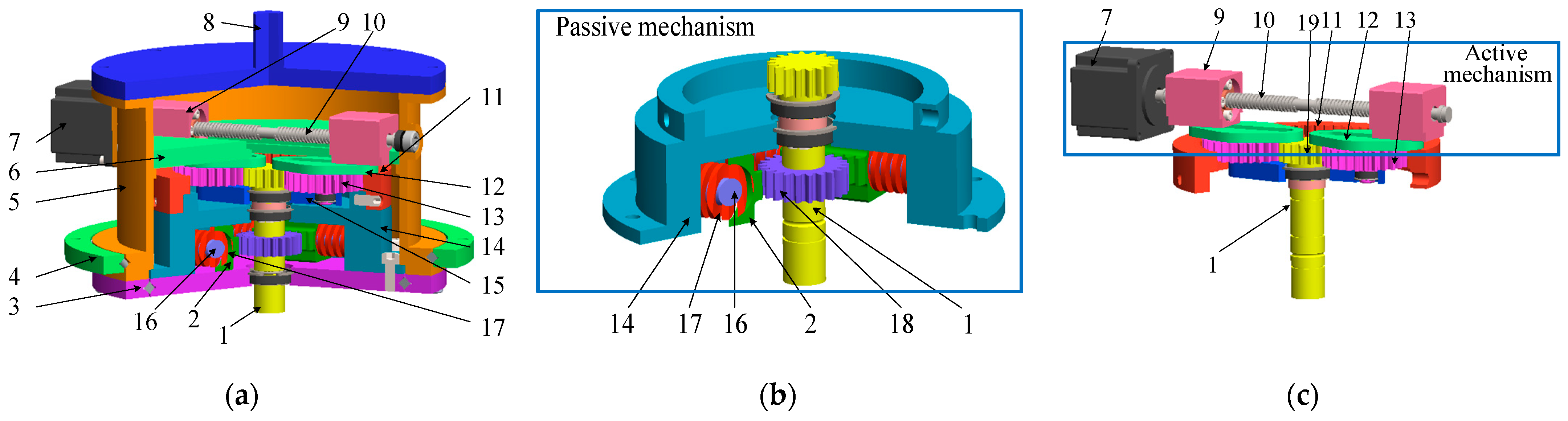
  • The variable stiffness actuator is designed with two different mechanisms acting as the first and second stages of stiffness regulation. The first stage can store energy and absorb shocks of the input shaft. The second stage can be applied to bear heavy loads by an active motor.
  • The required output torque can be adjusted to regulate the actuator stiffness.
  • Two pairs of the rack-and-pinion systems of the first stage and the two pairs of the planetary gears of the second stage are arranged side by side, improving the stability and balance of the stiffness regulation process.
  • The two cam-slider mechanisms are symmetrically arranged as the leverage pivot, guaranteeing the synchronous movements of the two rollers inside the cam.
The mechanical design of the proposed actuator is described by the working principles and a developed CAD model. The strength analysis is verified utilizing ANSYS. Dynamic simulation of the actuator is established via MATLAB, and the simulation results are validated against prototype experiments, indicating good mechanical performance of the proposed design strategy.

2. Materials and Methods

The proposed variable stiffness actuator with two different mechanisms acting as the first stage and the second stage in stiffness regulation is shown in Figure 1a. The actuator includes two parts. The first mechanism, which is considered the passive mechanism, is presented in Figure 1b, and the second, which is considered the active mechanism, is presented in Figure 1c.
The first mechanism is connected to the input shaft. When the input torque activates the input shaft, the first mechanism can elastically convert the shaft’s rotation into the inner shell’s rotation fixed to the second mechanism’s internal gear. Then, the internal gear drives the second mechanism to generate resistive forces against the rotation direction of the input shaft, providing the output angle of the output shaft.

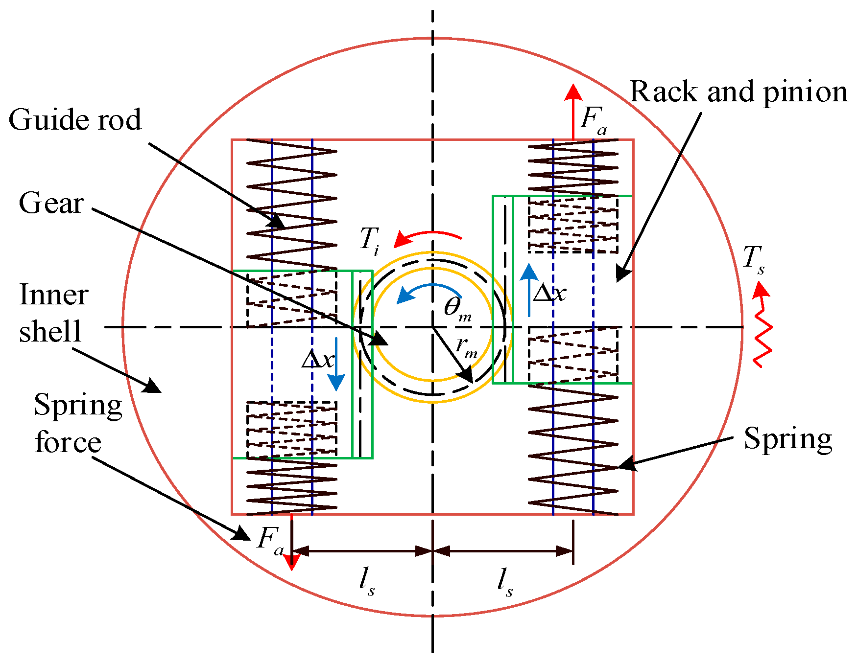
2.1. First Mechanism Design

The first mechanism design with variable stiffness is shown in Figure 1b and Figure 2. The mechanism includes a drive gear fixed to the input shaft, two rack-and-pinion systems, two linear springs, and an inner shell. The two pairs of rack-and-pinion systems [24] are arranged side by side to improve the stability and balance of the stiffness regulation process. The first mechanism acts as the first stage to adjust the stiffness.
As shown in Figure 2, the input torque T i and the input angle θ m applied to the input shaft are transferred to the rack-and-pinion systems via the drive gear fixed to the input shaft. The rotation of the drive gear is converted into the linear motion of the rack-and-pinion systems. Then, the rack gear drives the linear springs to be compressed or stretched, providing the spring force F a and causing a resultant torque T s that can be expressed as
T s = 2 F a l s = 2 k θ m r m l s ,
where   F a is the load applied to the springs, k is the spring’s stiffness, r m is the radius of the gear’s indexing circle, and l s is the distance between the center of the input shaft and the rack gear. The torque rotates the inner shell connected to the internal gear of the second mechanism. Then, the rotation angle of the inner shell relative to the input shaft can be obtained, which is considered the first stage of stiffness regulation.
The variable stiffness in the first mechanism is achieved via the linear motions of the springs driven by the rack-and-pinion systems, supplying the elasticity of the inner shell rotation, storing energy, and absorbing shocks of the input shaft [25,26].

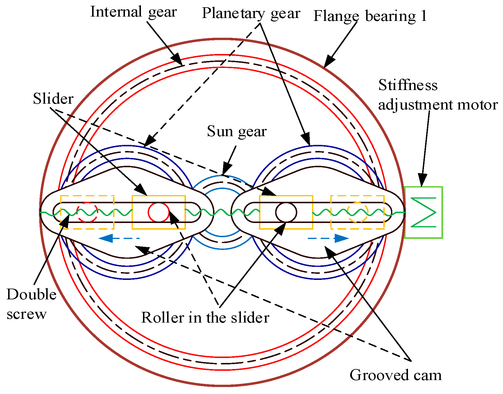
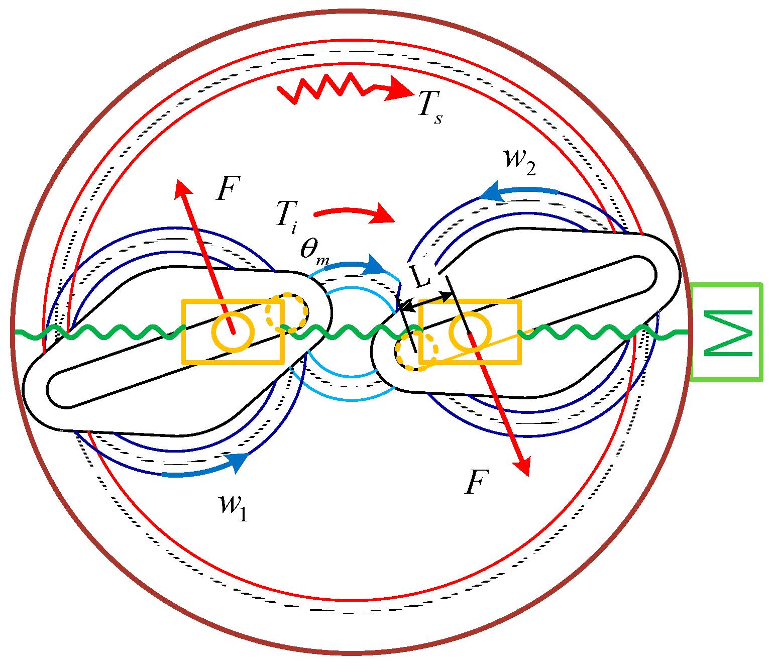
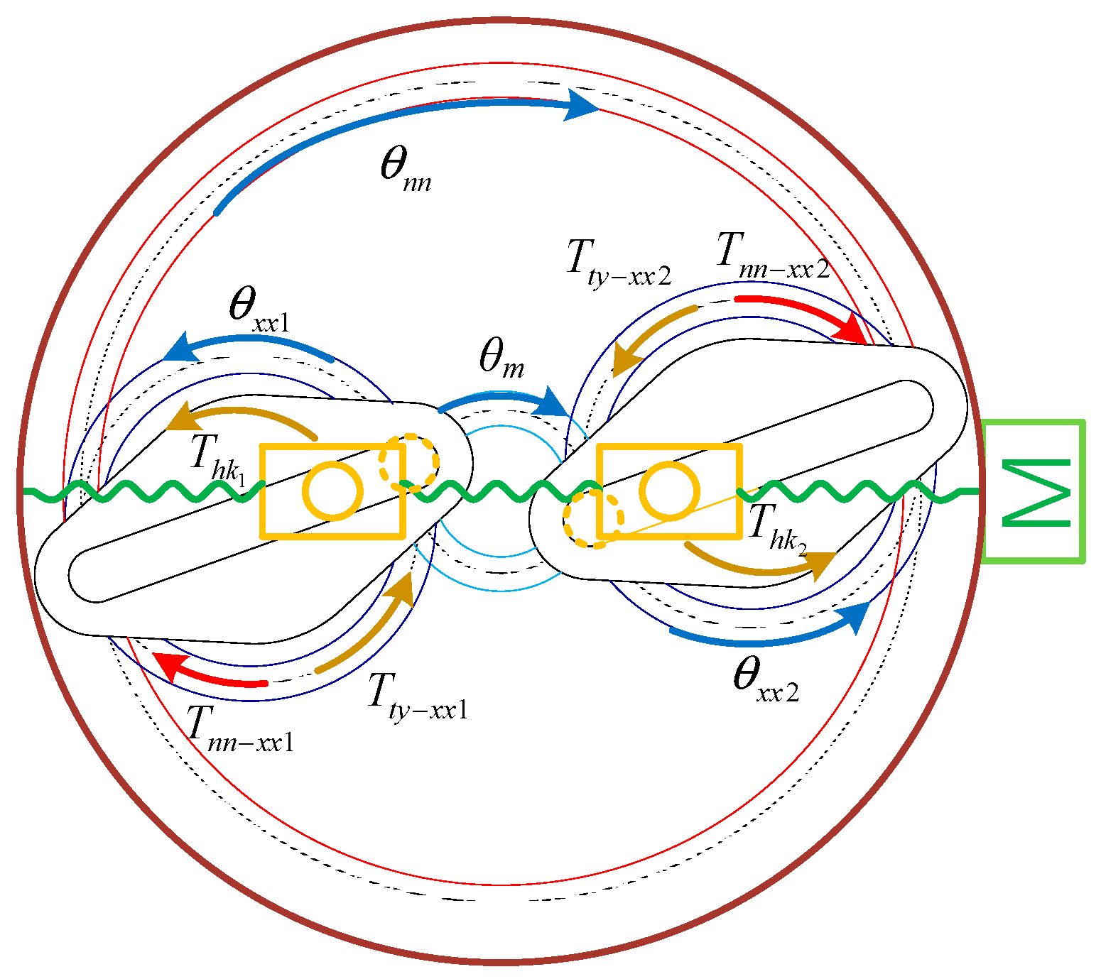
2.2. Second Mechanism Design

The second mechanism is devised based on the first mechanism to control the output angle of the output shaft, generating the stiffness of the proposed actuator. The second mechanism is shown in Figure 1c and Figure 3. The mechanism includes an internal gear, two planetary gears, a sun gear, two grooved cams [27], a pair of ball screws, two sliders, and an active motor. Each roller is placed inside a grooved cam and a slider. The sun gear is fixed to the input shaft. The second stage’s two pairs of planetary gears are placed side by side to enhance the stability and balance of the stiffness regulation process [28,29,30].
As shown in Figure 3 and Figure 4, the planetary gear is located between the internal gear, driven by the resultant torque T s of the first mechanism and the sun gear, fixed to the input shaft and driven by the input torque T i . Hence, the planetary gear rotation is caused by the sum torque of T i and the internal gear torque of T s . The total torque squeezes a force F with respect to the balance of the planetary gear, which acts on the roller placed inside the grooved cam fixed to the planetary gear. Since the directions of the two torques are opposite, the final squeezed force generated by the total torque can be reduced compared to the one generated by the input torque.
As described in Figure 4 and Figure 5, the roller is considered the pivot and moved along the linear groove of the grooved cam via the slider’s linear motion, which is actuated by a ball screw mechanism driven by an active motor. The distance from the reference circle of the sun gear to the roller’s center is the length L of the lever arm. The squeezed force F and the length L are used to generate the torque M acting on the roller connected to the slider. The turning angle at the outputs is denoted as θ o u t , and r is the distance from the slider’s center to the sun wheel axis.
As shown in Figure 1, the sliders are connected to the guide plate fixed to the shell. Consequently, the torque M also acts on the shell and the output shaft. Adjusting the torque M can be achieved by modifying the length L and varying the pivot point position located on the roller.
Finally, the stiffness of the designed two-stage actuator can be calculated according to the difference between the output torque M and the angle difference Δ θ between the rotation angle θ m of the input shaft and the output angle θ o u t of the output shaft. The stiffness can be expressed as [31]:
K = M θ m θ o u t = f ( θ m , r , k ) Δ θ
.

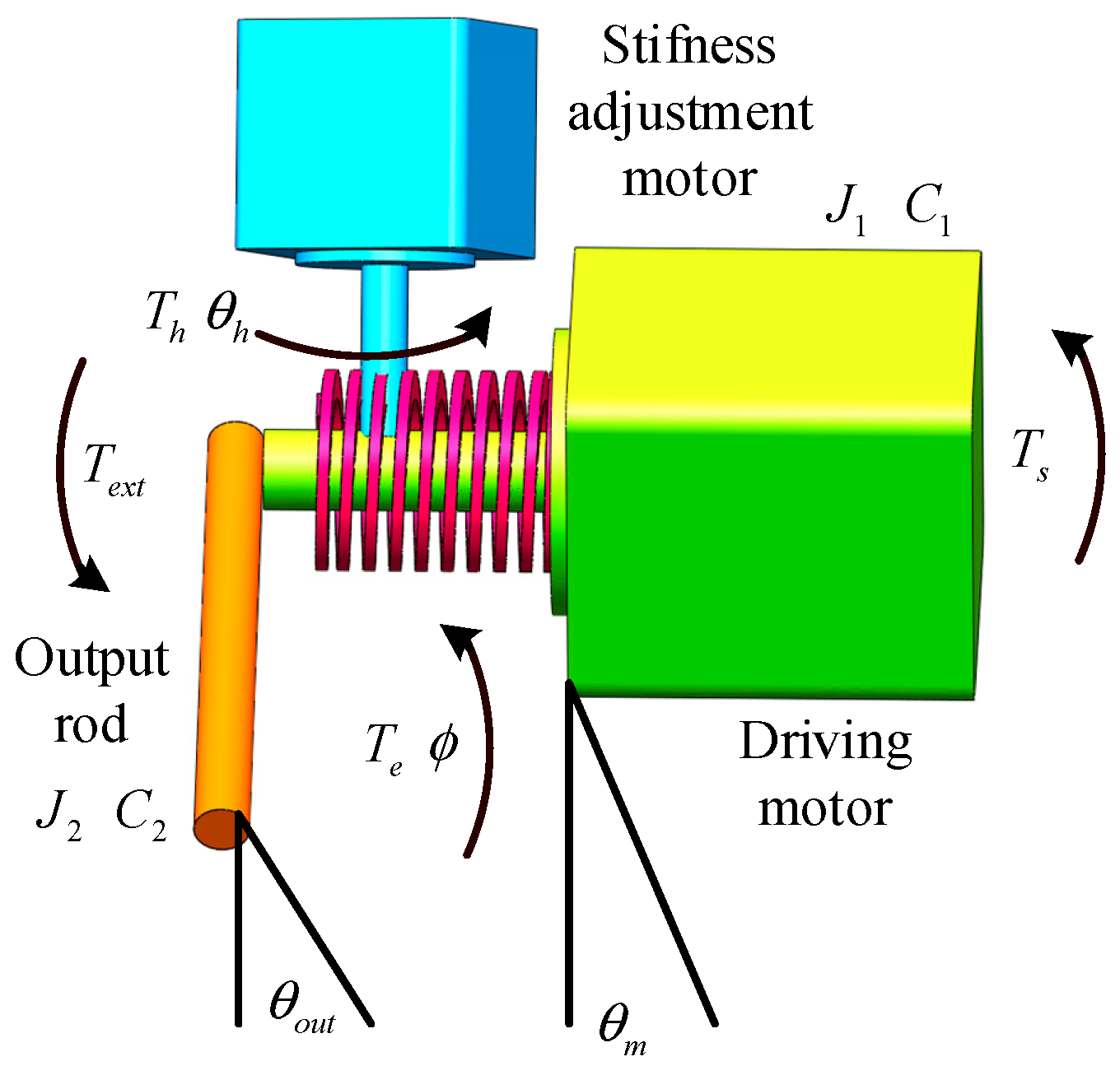
2.3. Mathematical Model for Describing the Dynamics of Developed Actuator

According to the designed actuator shown in Figure 1, it is simplified as presented in Figure 6. The driving motor and input shaft are regarded as the driving system; the guide plate, shell, and output shaft are together assumed as the output rod; the load is connected to the output rod; the planetary gear train, cam mechanism, rack-pinion, and springs are considered as torsion springs which are controlled by the stiffness adjustment motor.
On the basis of Figure 6, the mathematical model for describing the dynamics is established as
T s = J 1 θ ¨ m + C 1 θ ˙ m T e ϕ , θ h T e x t = J 2 θ ¨ o u t + C 2 θ ˙ o u t + T e ϕ , θ h ϕ = θ m θ o u t
where  T s , T e , and T e x t are, respectively, the output torque of the driving motor, the flexible torque generated by the torsion spring, and the load torque applied on the output rod; θ m , θ h , θ o u t , and ϕ are the output angle of the driving motor, the output angle of the adjusting motor, the output angle of the output rod, and the flexible angle generated by the torsion spring; J 1 and J 2 are the moments of inertia of the driving motor and the adjusting motor, respectively; C 1 and C 2 are the damping coefficients of the driving motor and the adjusting motor, respectively, which are simplified to include the effects of backlash, clearance function between gears, and friction forces between the cams and sliders, planetary gears and internal gears, planetary gears and sun gear, motors, and driven mechanisms.
The recursive least square method is used to identify the moments of inertia and damping coefficients. The calculation results are shown in Figure 7. The numerical values are finally achieved as J 1 = 4.6 × 1 0 5 k g m m 2 , C 1 = 20 N m m s / r a d , J 2 = 2.8 × 1 0 5 k g m m 2 , C 2 = 30 N m m s / r a d .

2.4. Stiffness Modelling

According to the dynamic model of the mechanism for stiffness regulation, as shown in Figure 8, the generated torques T n n x x 1 and T n n x x 2 can expressed as [32]
T n n x x 1 = K xx n n r n n f r n n θ n n r x x 1 θ x x 1 e x n ( t ) , b x n               + C x x n n r n n r n n θ ˙ n n r x x 1 θ ˙ x x 1 e ˙ x n ( t ) T n n x x 2 = K x x n n r n n f r n n θ n n r x x 2 θ x x 2 e x n ( t ) , b x n               + C x x n n r n n r n n θ ˙ n n r x x 2 θ ˙ x x 2 e ˙ x n ( t ) ,
where K x x n n is the time-varying stiffness between the engaging gear of the internal gear and the planetary gear; C x x n n is the damping coefficient between the internal gear and the planetary gear; θ n n   is the rotation angle of the internal gear; θ x x 1 is the rotation angle of planetary gear 1; θ x x 2 is the rotation angle of planetary gear 2; f r x x i θ x x i r n n θ n n e x n ( t ) , b x n is the clearance function between the internal gear and the planetary gear; i = 1,2 ; e x n t is the comprehensive transmission error between the planetary gear and the internal gear; b x n is the clearance error between the internal gear and planetary gear; r n n is the radius of the internal gear’s indexing circle; r x x 1 is the radius of planetary gear 1′s indexing circle; and r x x 2 is the radius of planetary gear 2′s indexing circle.
As presented in Figure 8, T t y x x 1 , which is the torque generated by the sun gear and applied on the planetary gear 1, and T t y x x 2 , which is the torque generated by the sun gear and applied on the planetary gear 2, can be written as [32]
T t y x x 1 = K t y x x r t y f r t y θ m r x x 1 θ x x 1 e x t ( t ) , b x t               + C t y x x r t y r t y θ ˙ m r x x 1 θ ˙ x x 1 e ˙ x t ( t ) T t y x x 2 = K t y x x r t y f r t y θ m r x x 2 θ x x 2 e x t ( t ) , b x t               + C t y x x r t y r t y θ ˙ m r x x 2 θ ˙ x x 2 e ˙ x t ( t ) ,
where K t y x x is the time-varying stiffness between the engaging gear of the sun gear and planetary gear; C t y x x is the damping coefficient between the sun gear and planetary gear; f r t y θ m r x x i θ x x i e x t ( t ) , b x t is the clearance function between the sun gear and the planetary gear with i = 1,2 ; e x t t   is the comprehensive transmission error between the planetary gear and the sun gear; b x t   is the clearance error between the sun gear and the planetary gear; r t y is the radius of the sun gear’s indexing circle.
As described in Figure 8, according to Equations (4) and (5), the torque applied on the slider by the planetary gear can be regarded as the output torque, and it is presented as
T h k 1 = J xx 1 θ ¨ x x 1 + K t y x x r t y f r t y θ m r x x 1 θ x x 1 e x t ( t ) , b x t           + C t y x x r t y r t y θ ˙ m r x x 1 θ ˙ x x 1 e ˙ x t ( t )           K xx n n r n n f r n n θ n n r x x 1 θ x x 1 e x n ( t ) , b x n           C x x n n r n n r n n θ ˙ n n r x x 1 θ ˙ x x 1 e ˙ x n ( t ) T h k 2 = J xx 2 θ ¨ x x 2 + K t y x x r t y f r t y θ m r x x 2 θ x x 2 e x t ( t ) , b x t           + C t y x x r t y r t y θ ˙ m r x x 2 θ ˙ x x 2 e ˙ x t ( t )           K xx n n r n n f r n n θ n n r x x 2 θ x x 2 e x n ( t ) , b x n           C x x n n r n n r n n θ ˙ n n r x x 2 θ ˙ x x 2 e ˙ x n ( t ) ,
where J xx 1 is the effective moment of inertia of planetary gear 1 and grooved cam 1; J xx 2 is the effective moment of inertia of planetary gear 2 and grooved cam 2; T h k 1 is the torque generated by grooved cam 1 and applied on the slider 1; T h k 2 is the torque generated by grooved cam 1 and applied on the slider 2.
As demonstrated in Figure 9, the initial center of the sun gear is at the position   o , the initial center of the planetary gear is at the position   o , the line connecting the two centers is rotated by φ j , and the center of the planetary gear is rotated from position o to o , the rotation angle of the sun gear is θ m . F d b   is the force generated by the slider and applied on the grooved cam; F h k   is the force generated by planetary gear and applied on the slider; T h d is the torque which equals the T h k ; H   is the displacement of the slider along the ball screw.
Then, the following equations can be obtained as
H 2 + r t y + r x x 2 2 H r t y + r x x cos φ j sin φ j = H sin θ x x F h k H 2 + r t y + r x x 2 2 H r t y + r x x cos φ j = T h k F d b = F h k cos θ x x + φ j T h d = F d b H ,
According to the Equation (7), the stiffness model can be written as
H 2 + r t y + r x x 2 2 H r t y + r x x cos φ j sin φ j = H sin θ x x K = 2 T h k H cos θ x x + φ j θ m θ s H 2 + r t y + r x x 2 2 H r t y + r x x cos φ j .

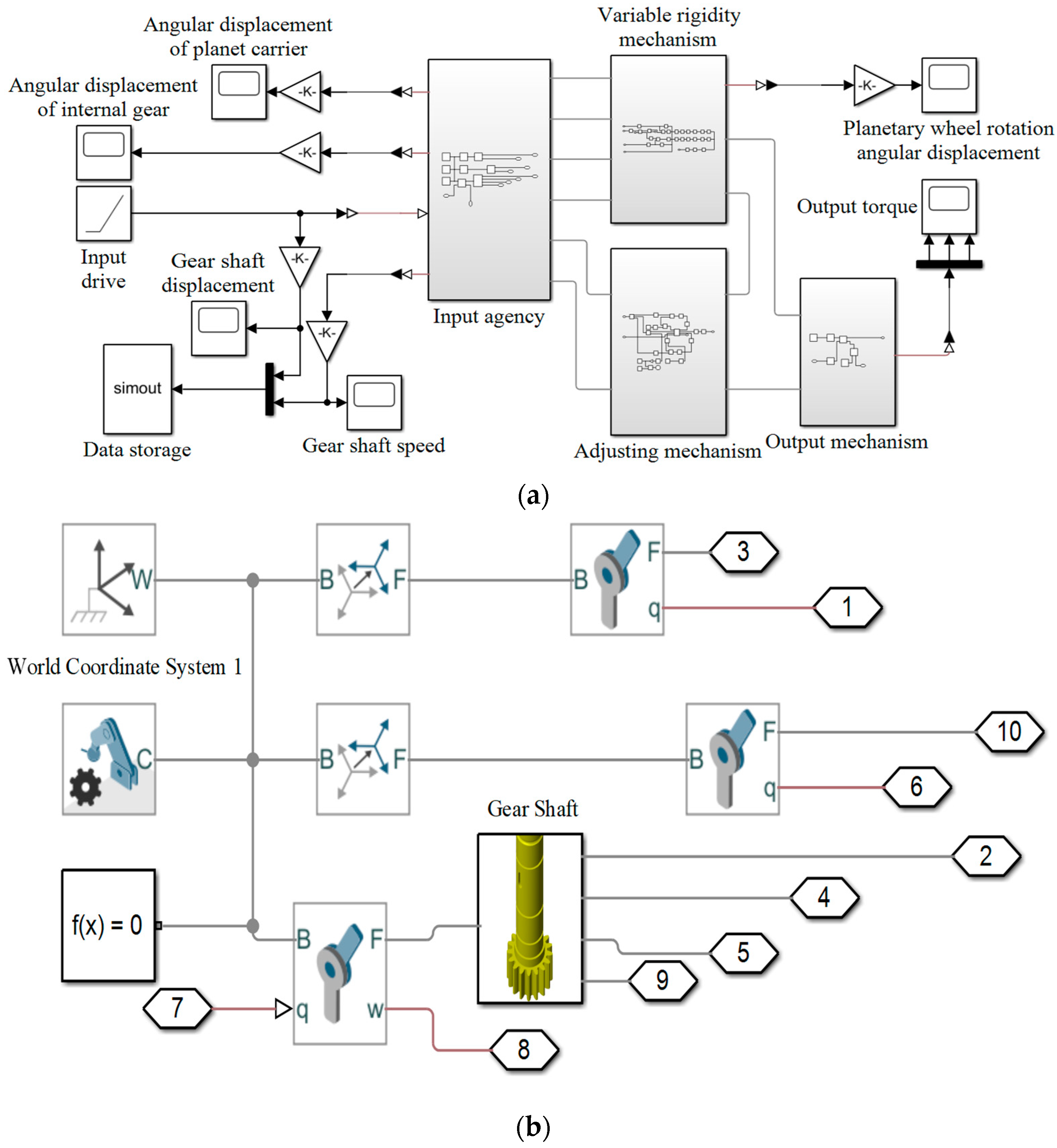
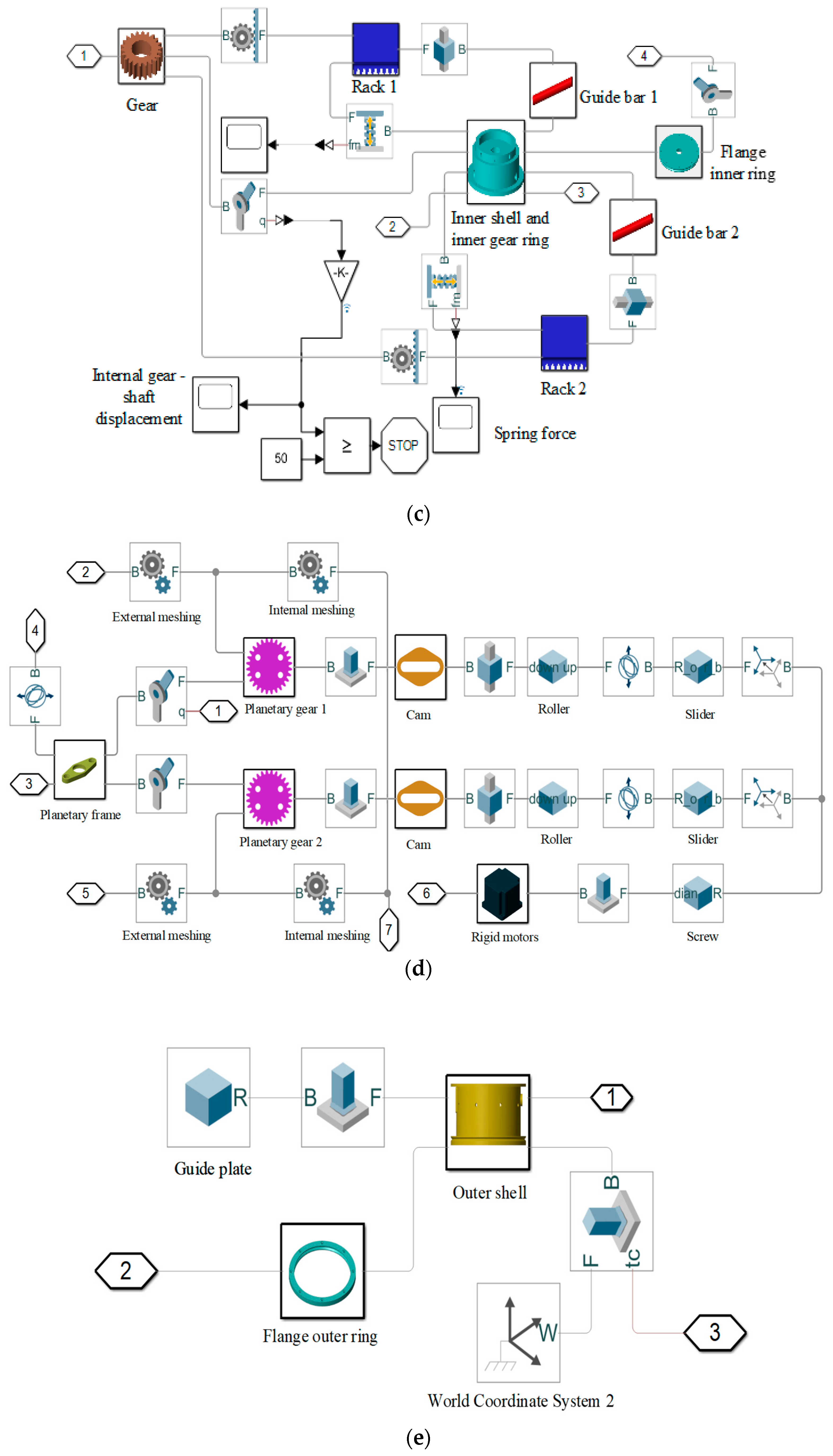
2.5. Simulation Setup

The mechanical design of the proposed variable stiffness actuator for stiffness regulation developed with the schematic CAD model is shown in Figure 1 and Figure 10.
The diameter of the actuator is 224 mm, the height is 165 mm, and the linear spring is 45 mm long. The maximum rotation angle Δ θ m a x of the input shaft is achieved at 50°. Gears’ dimensions are shown in Table 1, and spring’s dimensions are shown in Table 2.
SimMechanics of MATLAB/Simulink is employed to establish the dynamics simulation model, as shown in Figure 11a. The dynamics simulation model’s input, first, second, and output mechanisms are shown in Figure 11b–e, respectively. The flexibility of gear tooth and lubrication are neglected in the analysis.

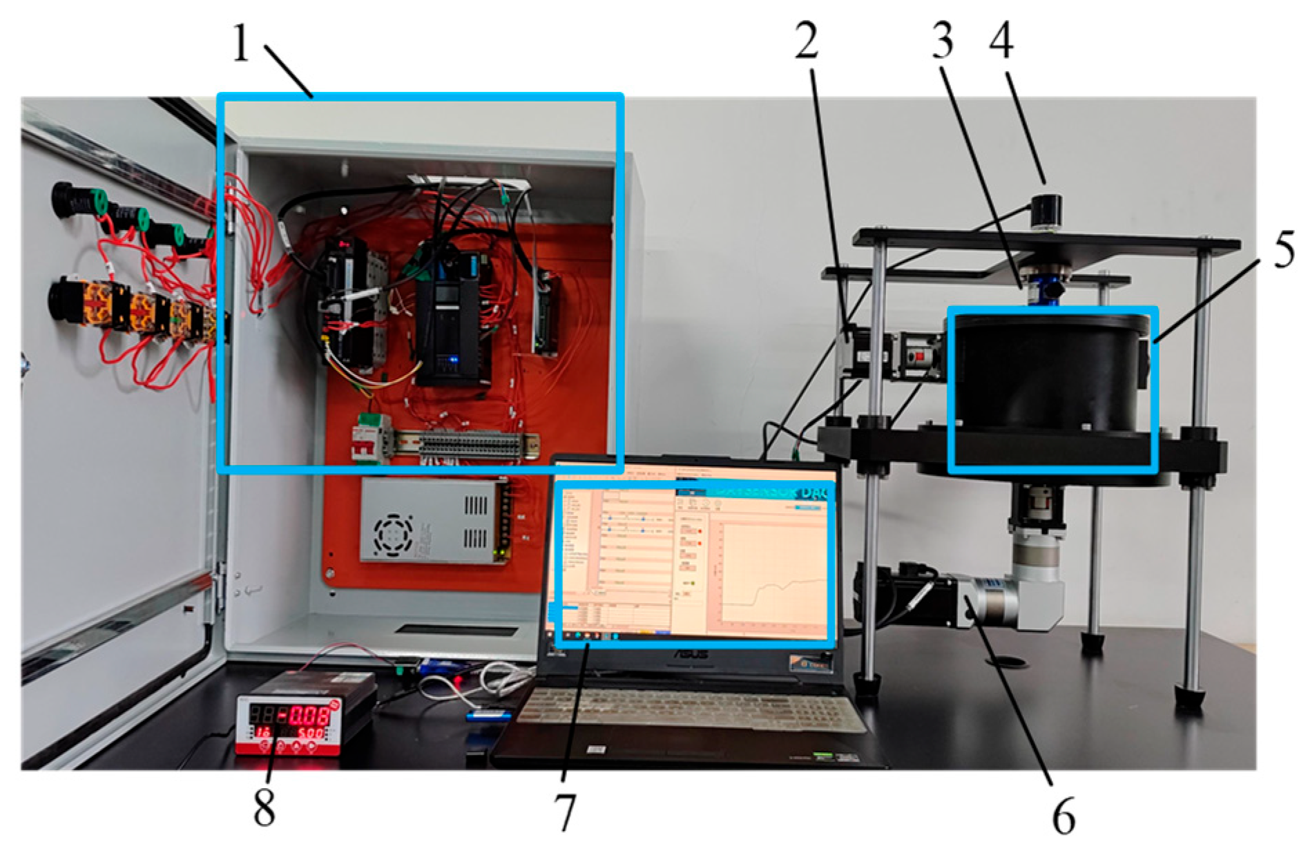
2.6. Experimental Setup

The prototype experiments are conducted on the designed actuator, as shown in Figure 12. The actuator’s maximum flexibility angle Δ θ m a x and output torque T m a x   are obtained by combining the built experimental platform with the Simulink simulation model. The actuator’s stiffness is calculated as T m a x Δ θ m a x , where the experimental data are separately measured by a torque sensor, DAYSENSOR DYJN-101, and an encoder, OMRON E6B2-CWZ6C. The distances are measured by using the laser displacement sensor KEYENCE LR-X from Tokyo, Japan with a detection error of 0.5 mm.

3. Results

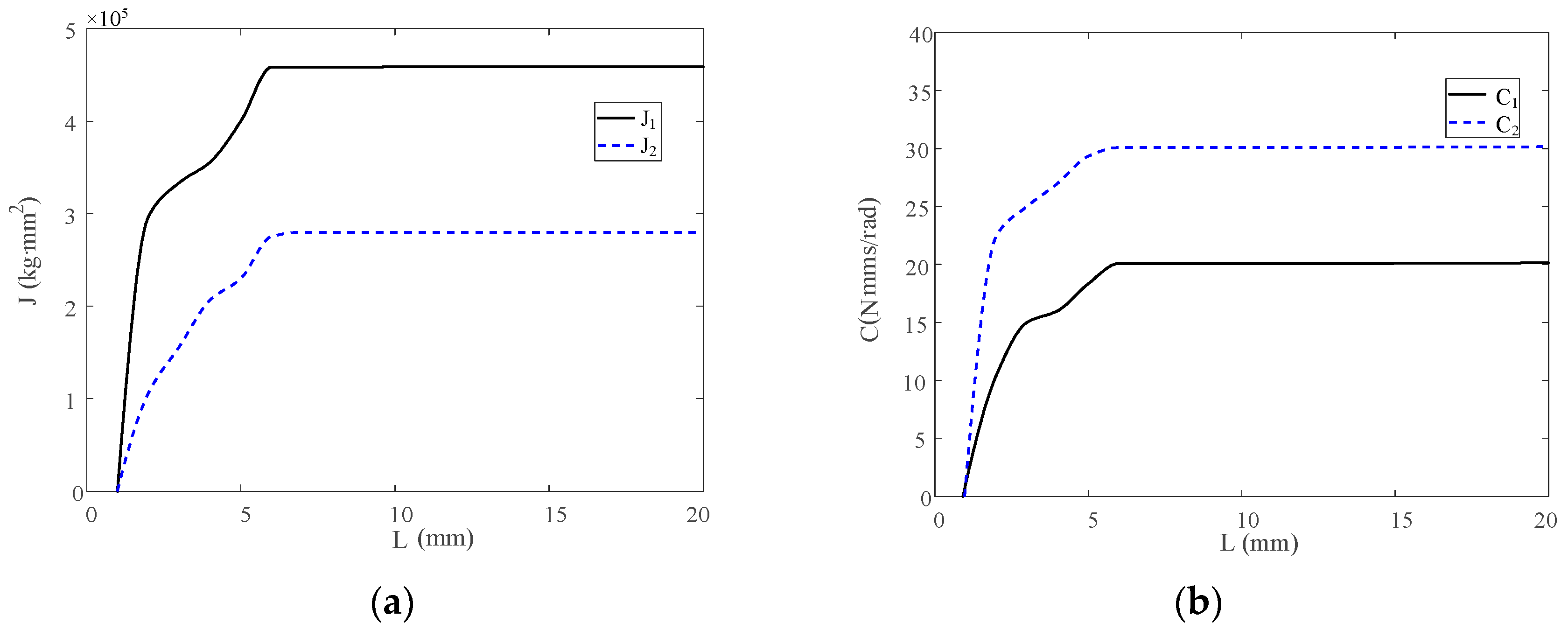
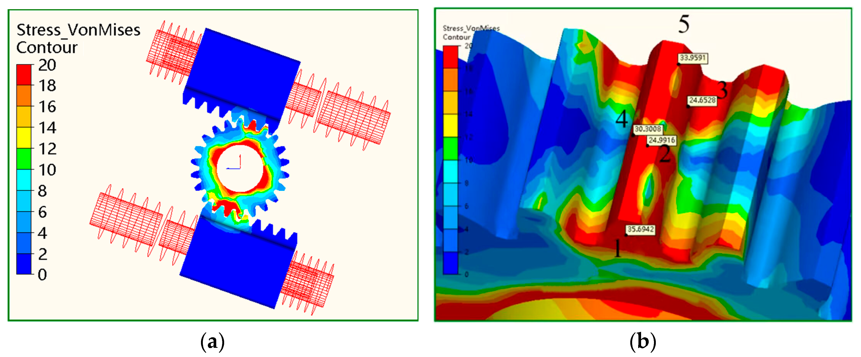
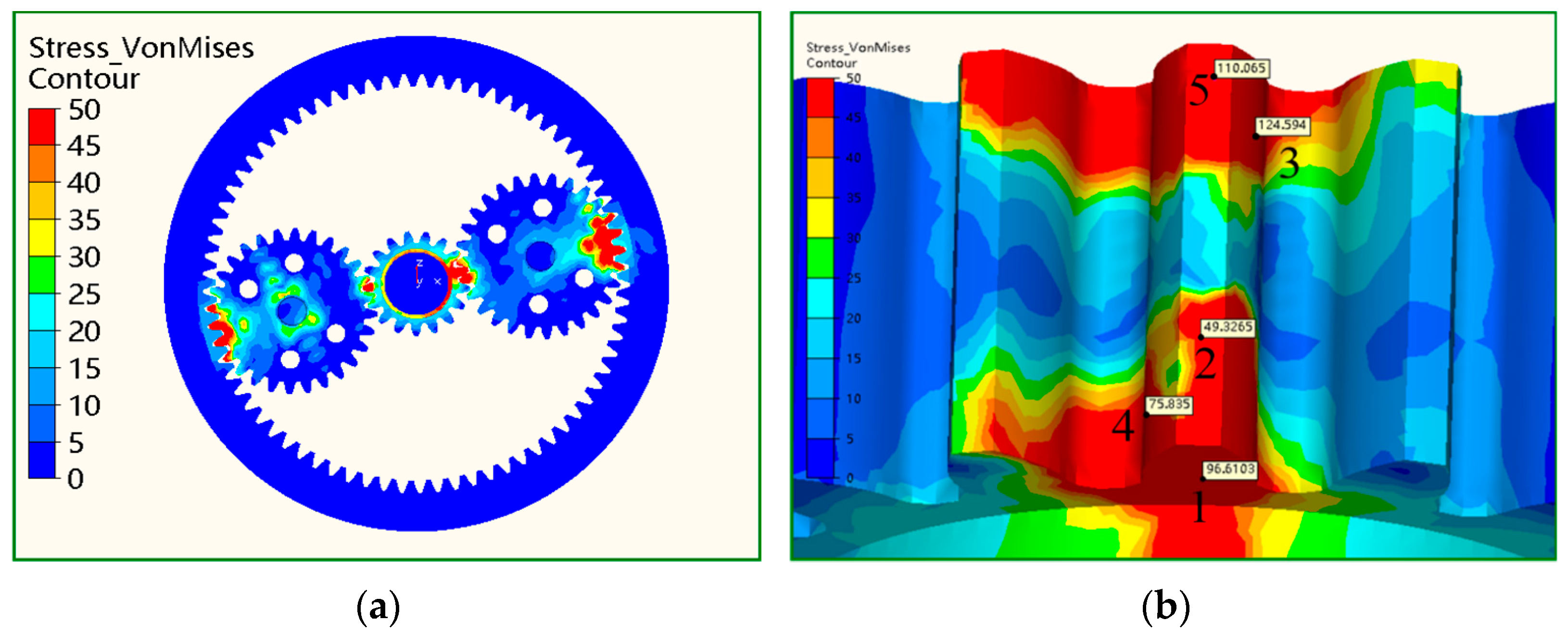
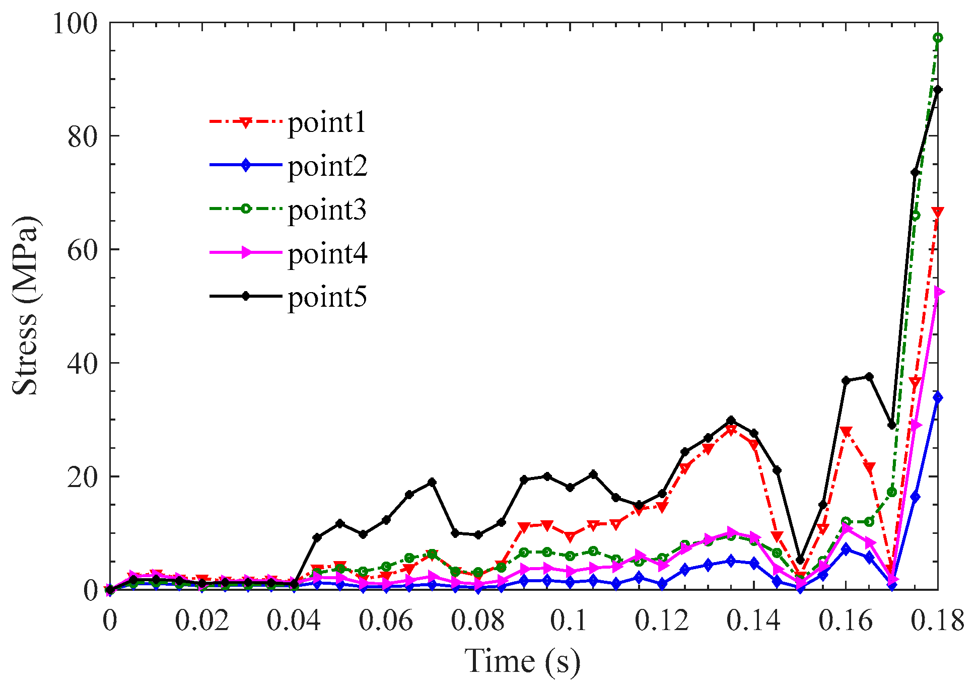
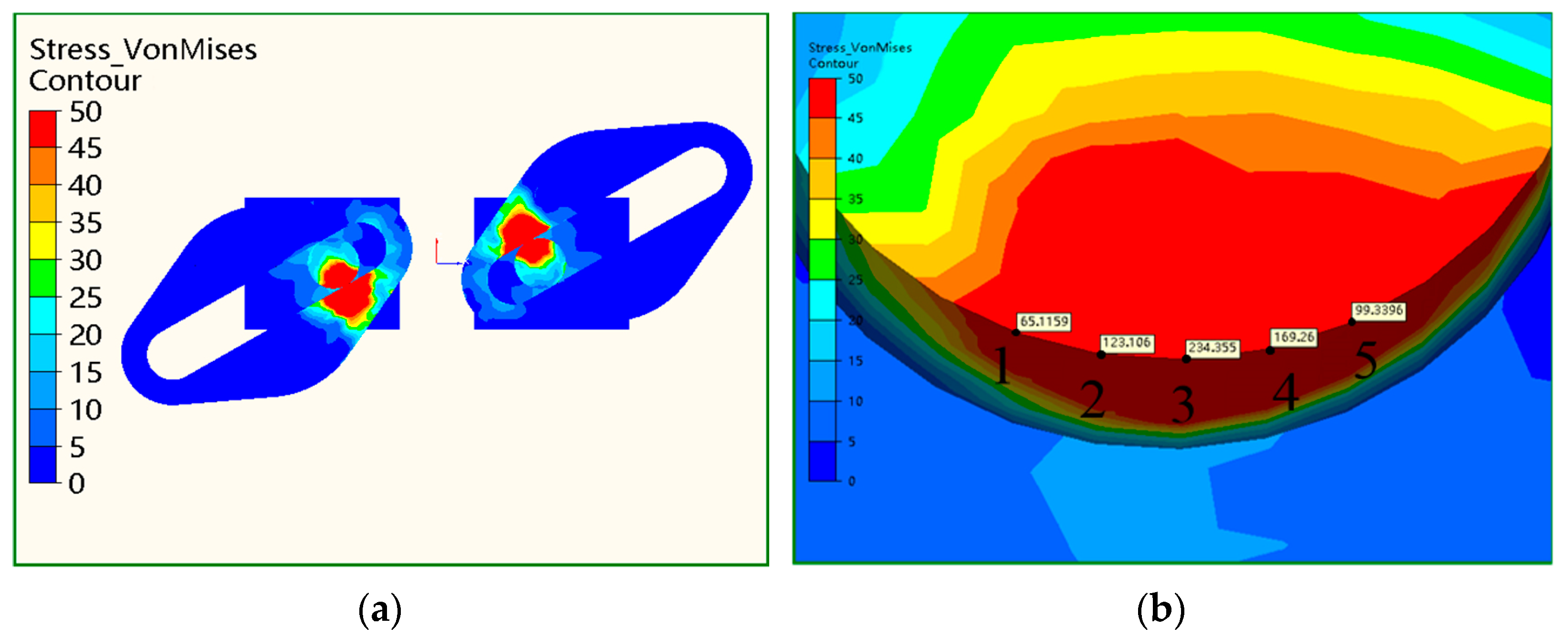
3.1. Strength Analysis

The dynamic system of the designed actuator is established using ANSYS Motion 2019 R2 to analyze the contact forces between two contact surfaces of different components during operation. The analysis does not include the flexibility of the gear tooth and lubrication. The output shaft is assumed to be fixed during the simulation. The springs of the first mechanism are loaded by the rated loads and used as the stop signal for the working actuator. The gears are made of 40 Cr, whose parameters are listed in Table 3. Lastly, the input angle is taken as 60° for simulations.
The stress of the rack-and-pinion system shown in Figure 13a indicates that higher stresses are located on the pinion gear. Five nodes of the pinion gear shown in Figure 13b are chosen. It can be seen that the maximum stress is lower than 40 MPa, which is smaller than the yield strength of the material (40 Cr) [33] of the pinion gear.
The stresses of the planetary gears, internal gear, and sun gear are shown in Figure 14a. The stresses at the contact surfaces are higher than those of the other parts, which is consistent with the actual observation. Five nodes at the teeth of sun gear during the engagement, shown in Figure 14b, are chosen. Their stresses at different times during the operation are shown in Figure 15, which suggests that the stress-changing trends of the nodes are similar. The maximum stress is 97.28 MPa, lower than the yield strength of the material 40Cr of the gears. Hence, the gears meet the strength requirements.
The stresses of the rollers and the grooved cams are shown in Figure 16a, demonstrating that the stresses of the two pairs of roller and cams are similar due to the symmetrical arrangement. Moreover, higher stresses are distributed over the areas around the contact surface between the roller and the cam, which conforms to the distribution law of contact stress.
Five evenly distributed nodes along the contacted edge of the roller are selected, as demonstrated in Figure 16b. Their stresses at different times during the working process are plotted and shown in Figure 17. The stress-changing trends of the nodes are similar. The maximum stress is 268.72 MPa and is lower than the yield strength of 40Cr, meeting the strength requirement. If the strength of the designed mechanism does not meet the strength requirements, invalid motions and structural damages can easily occur, such as fractures and cracks. The conducted analyses indicate that the closer the node is to the contact region, the higher the stress is.

3.2. Stiffness Analysis of Simulation and Experimental Results

3.2.1. Stiffness Analysis of Simulation Results

The output shaft and shell are assumed to be fixed in the dynamics simulation, and the speed of the gear shaft is applied as 30°/s. The motion of the second mechanism for the abovementioned boundary conditions is shown in Figure 18.
The maximum angle difference between the input shaft and the internal gear is 60° when the maximum rated loads act upon the springs of the first mechanism. The parameter r shown in Figure 19a is selected to be 20 mm, 22.5 mm, 25 mm, 30 mm, 40 mm, and 50 mm, for which the simulation results of the output angles of the internal gear θ i g and the planetary gears θ p g are shown in Figure 19a,b. According to Figure 19b, the rotation angle of the internal gear changes more steeply as r decreases.
In Figure 19b, the rotation directions of planetary gears are different from that of the input shaft. According to Figure 19a,b, changing trends of the output angle of the internal gear and that of the planetary gears are similar.
According to Figure 19a,b, if the parameter r is in the range of 25–50 mm, the output angle of the internal gear behaves linearly with the input angle of the input shaft. Consequently, the output angle of the planetary gear is also linearly related to the shaft’s input angle. The simulation results imply that the output angles of the internal gear and the planetary gears change linearly with the input angle if the parameter r is 25–50 mm, suggesting the stiffness can be precisely controlled by adjusting the input angle. If the parameter r is 20–22.5 mm, the internal and planetary gear output angles are non-linearly related to the input angle. Therefore, it is difficult to control the stiffness.

3.2.2. Stiffness Analysis of Experimental Results

The maximum angular difference Δ θ m a x obtained by the simulation, the experiment and the theoretical is shown in Figure 20, suggesting that the angle increases with parameter r. The flexible angle changes quickly when parameter r is in the range of 20–25 mm. In contrast, the flexible angle changes gradually when the parameter r is 25–50 mm.
According to the simulation results, the flexibility angle varies in the range of (4.81°–47.1°). According to the theoretical results, the flexibility angle varies in the range of (5.9°–47.5°). According to the experimental results, the corresponding range is (7°–48°), i.e., similar trends can be observed. The difference occurs at r = 21.5 mm, and the maximum difference is 4°.
The actuator stiffness is demonstrated in Figure 21. It can be observed that the stiffness quickly increases as the parameter r decreases. When the parameter r is between 20.00 mm and 22.50 mm, the stiffness of the mechanism changes quickly. The stiffness changes slowly when the parameter r is between 22.50 mm and 50.00 mm. The effective stiffness range obtained by simulation is 51–3035 N·mm/deg, the experimental one is 35–3286 N·mm/deg, and the theoretical result is 28–3336 N·mm/deg. It can be concluded that the three change patterns are consistent and have small errors.
As shown in Figure 20 and Figure 21, the flexible angle and stiffness obtained by theoretical results are closer to that achieved by the experimental results than simulation results. They are very close to that achieved by the experimental results, indicating the theoretical stiffness modeling is effective. The effects of adjusted displacements should be included in the modeling of stiffness.

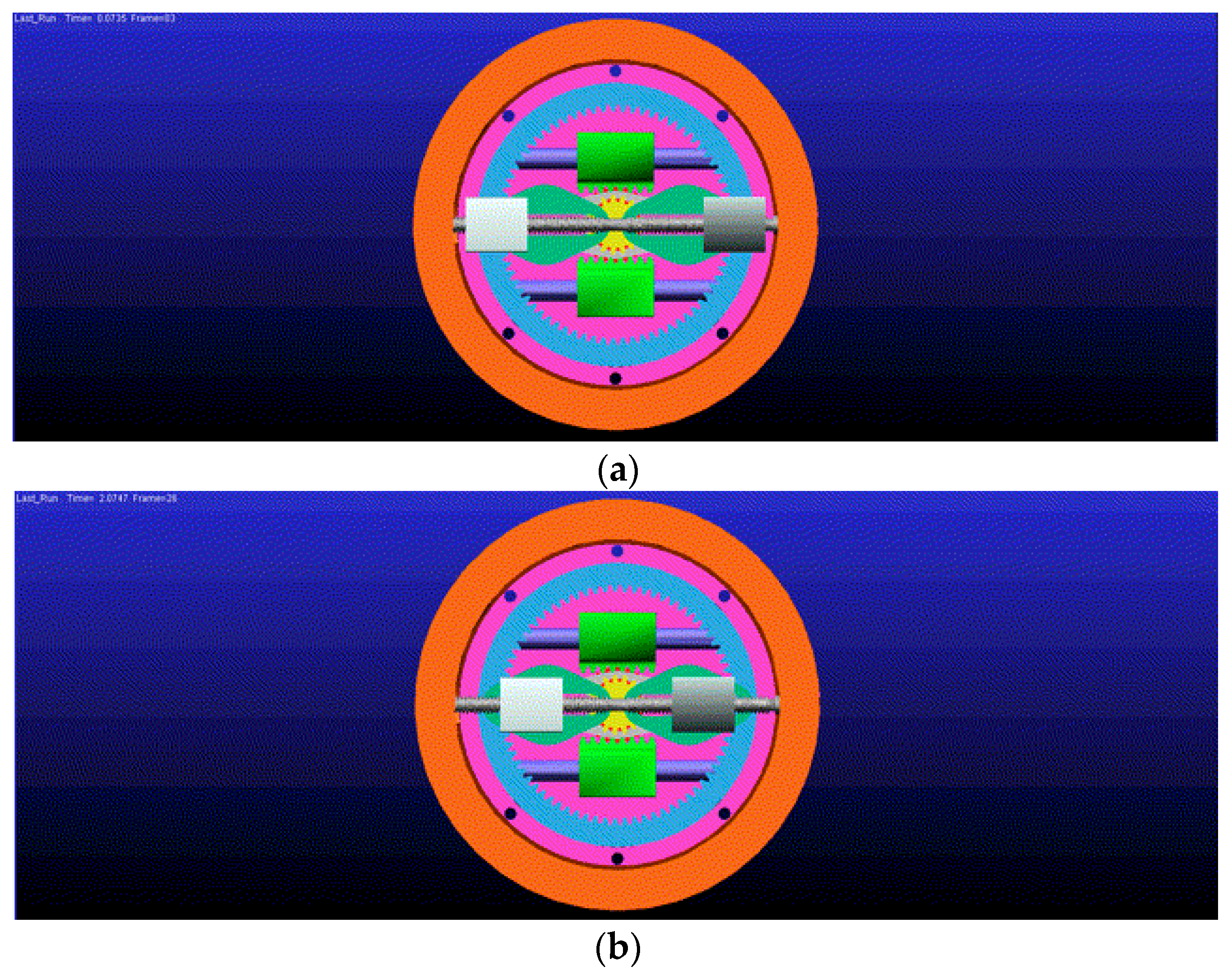
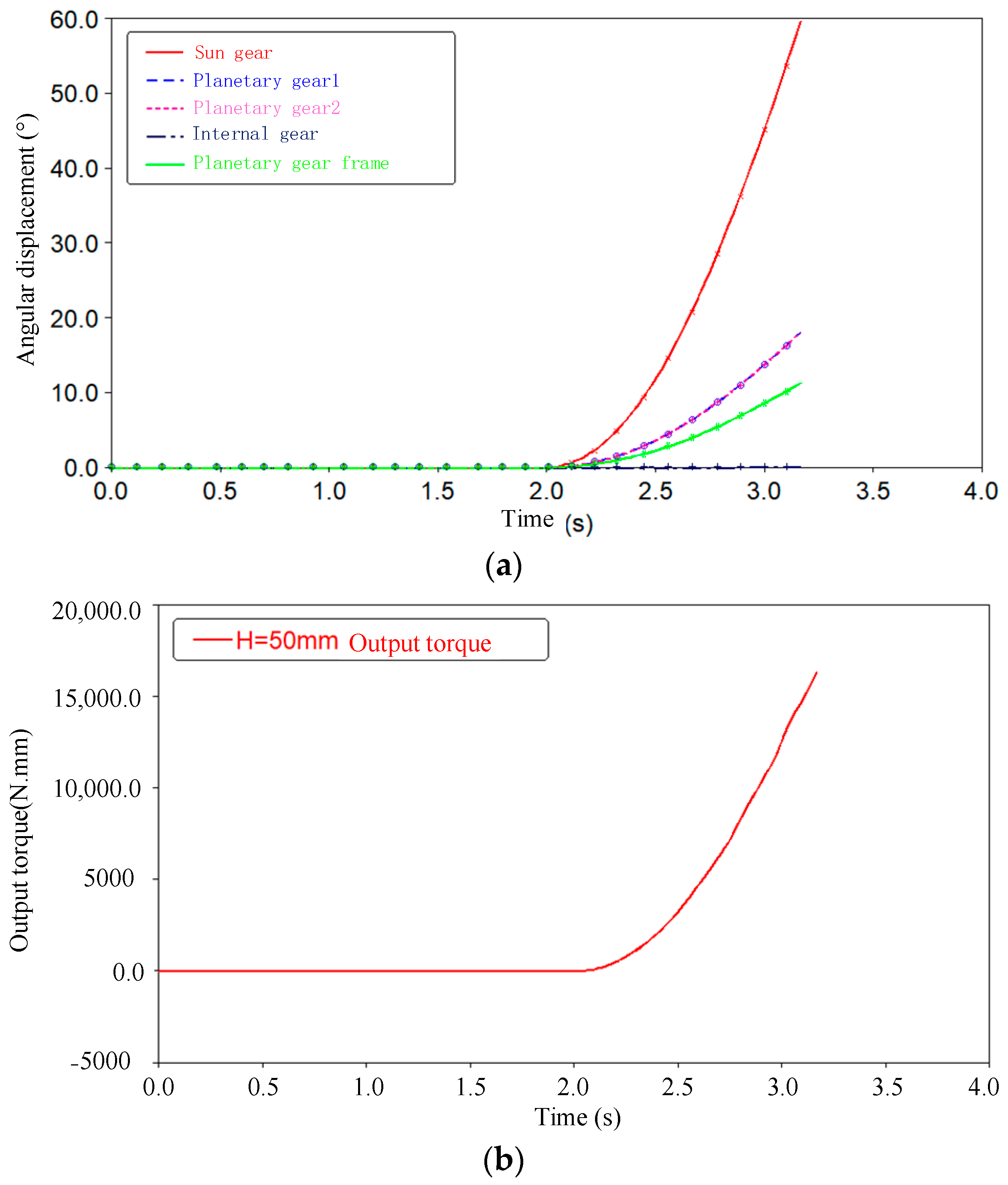
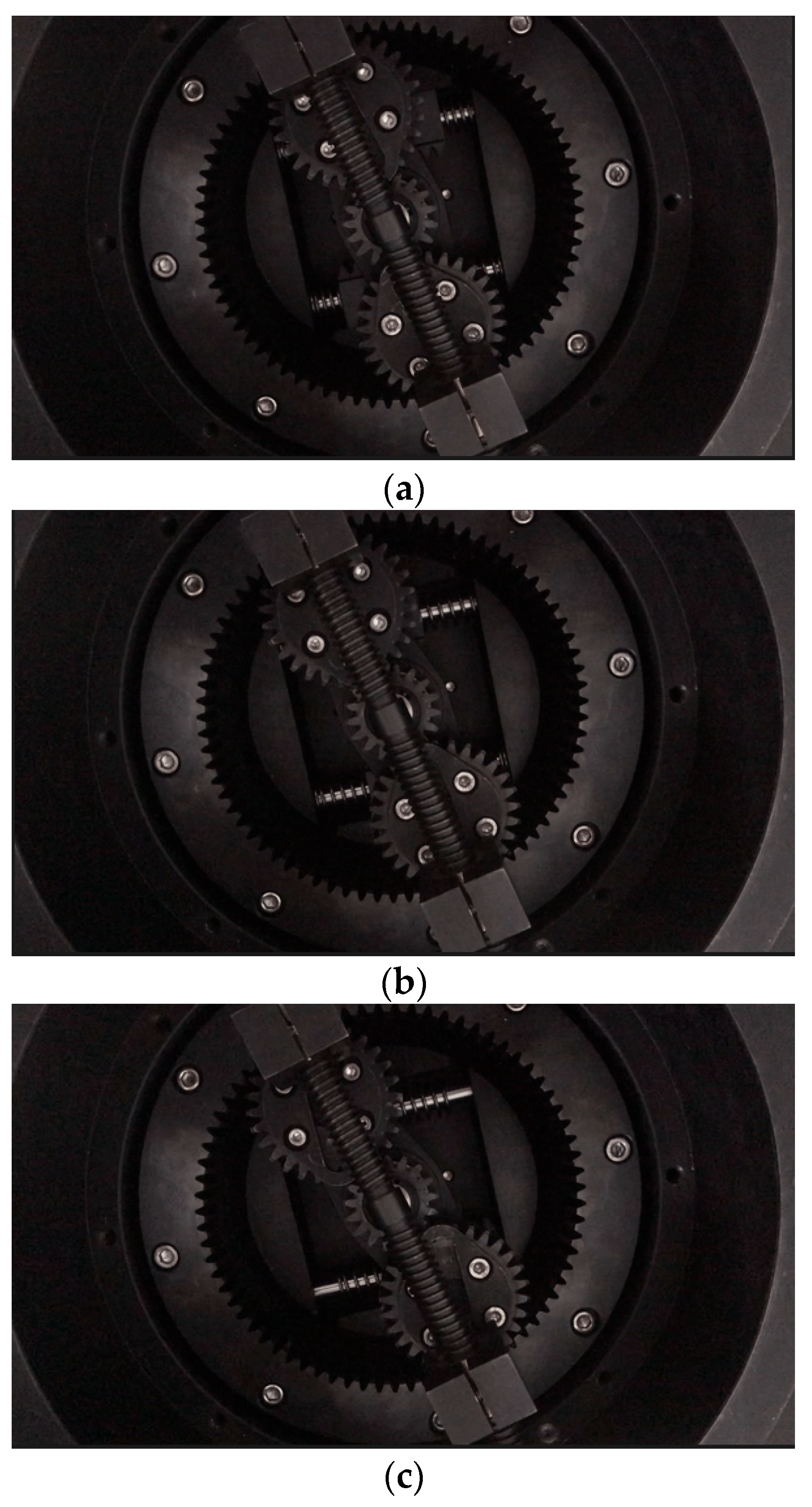
3.3. Simulation and Experiment of Dynamic Movements

To validate the dynamic movements of the designed actuator, the dynamic movements have been simulated by using ADAMS 2018. The animation is demonstrated in Figure 22, and it shows that the designed mechanism can move smoothly without a dead band.
The initial H is adjusted during a time of 0–2 s by a stiffness adjustment motor without input, the input shaft is driven by a rotational speed of 60°/s at a time of 2 s, and the output shaft is fixed. When H = 50 mm is set, the angle displacements of the sun gear, planetary gears, internal gear, and planetary gear frame are presented in Figure 23a. The output torque T h d is shown in Figure 23b.
The experiment of dynamic movements is presented in Figure 24. It indicates smooth movements.
The simulated and experimental dynamic movements are shown in Figure 22, Figure 23 and Figure 24, indicating that the designed mechanism can move smoothly without a dead band.

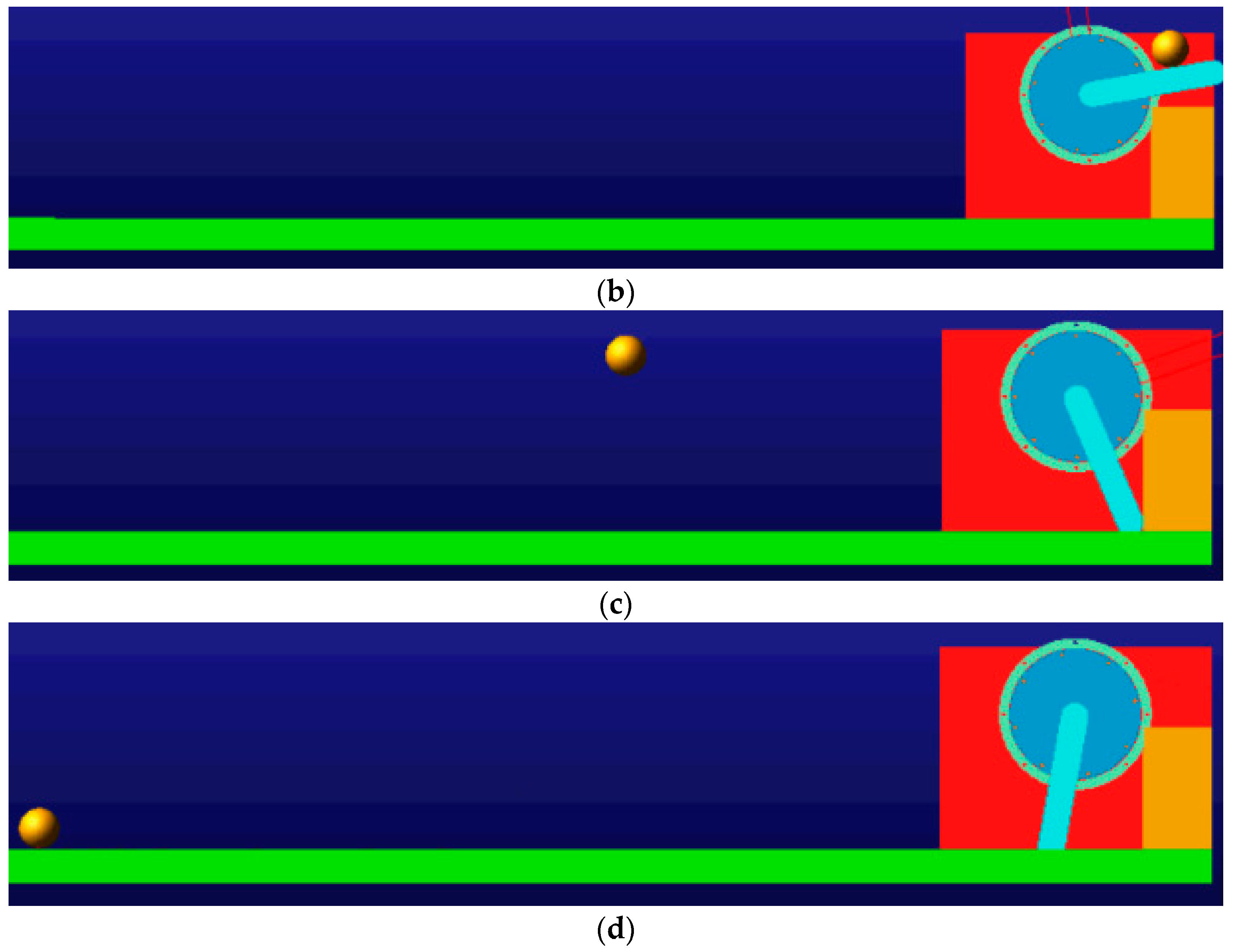
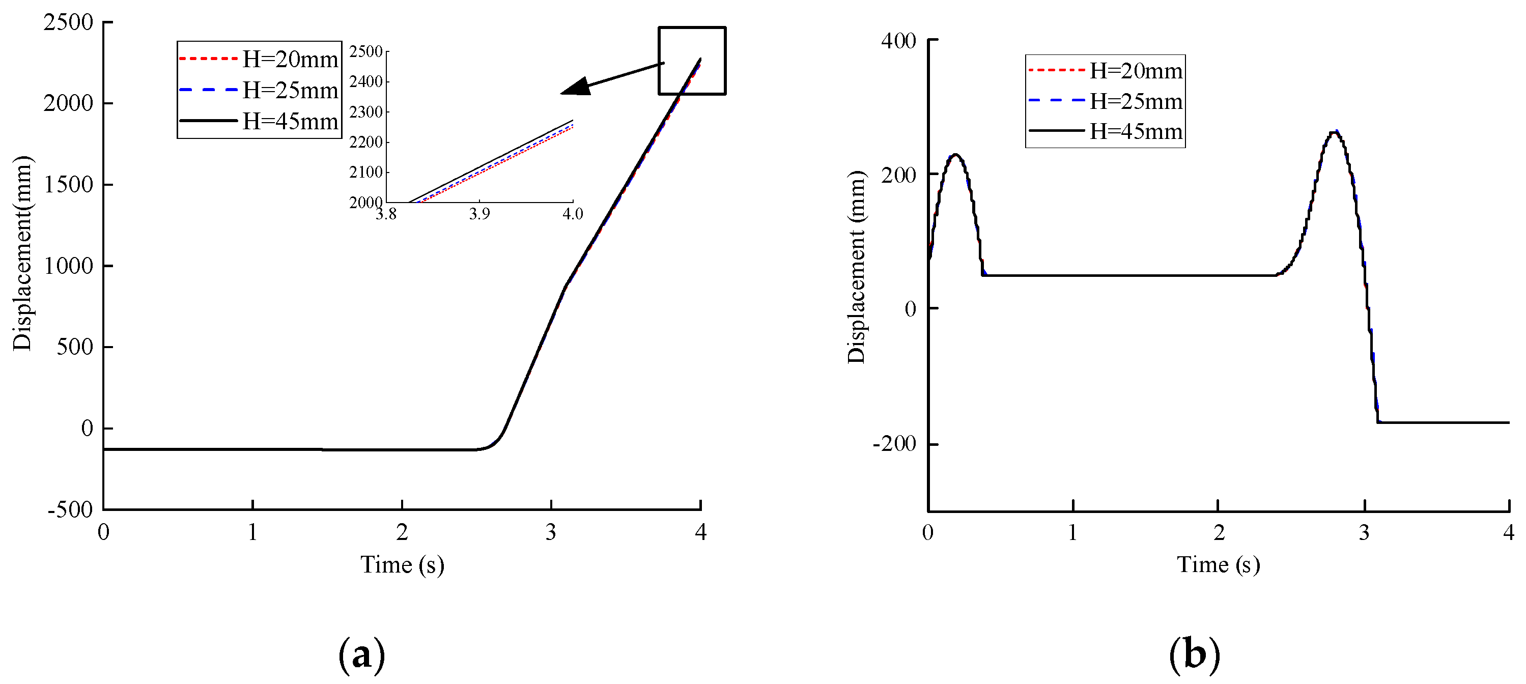
3.4. Ball Throwing Simulations

The ball throwing simulations have been carried out to verify the ability of energy storage of the designed actuator. A rigid output rod (length: 20 cm, width: 4 cm, height: 2 cm, mass: 1441 g) was affixed to the flange cover of the designed actuator. The terminal end of the output rod was used to support a small ball (radius: 3 cm, mass: 882 g), and the initial output linkage was set to be horizontal. The ball throwing simulations employing ADAMS are shown in Figure 25.
The displacements of the ball center in the horizontal direction and vertical direction are depicted in Figure 26.
As shown in Figure 25 and Figure 26, the output rod can be used to provide the ability of energy storage for throwing the small ball, indicating its performance of shock resistance.

3.5. Static Analysis and Dynamic Analysis of Shock Resistance Performance

To evaluate the shock resistance performance of the designed actuator, static simulation and dynamic simulation of shock resistance have been conducted by using ADAMS.

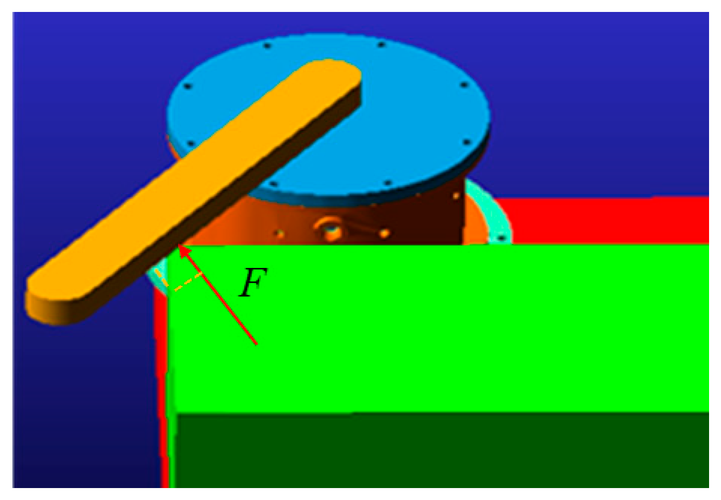
3.5.1. Static Analysis of Shock Resistance Performance

The input shaft of the actuator is fixed. The distance H = 40 mm is achieved by adjusting the sliders for 0–2 s. Then, a shock force with 50 N, which is parallel to the tangential direction of the output shaft, is applied on the point that is located at one-third of the shaft, as shown in Figure 27, from 2.1 to 2.2 s. The output torque T h d and the flexible angle φ j are shown in Figure 28.
As shown in Figure 28a,b, the vibrations of output torque and flexible angle can be observed after the shock force is applied. At the 2.12 s, the maximum vibration of the output torque reached 986.30 N·mm, and the maximum vibration of the flexible angle is 2.51°. Then, the vibrations can be suppressed by the actuators at about 4 s, indicating the capability of robust shock resistance.

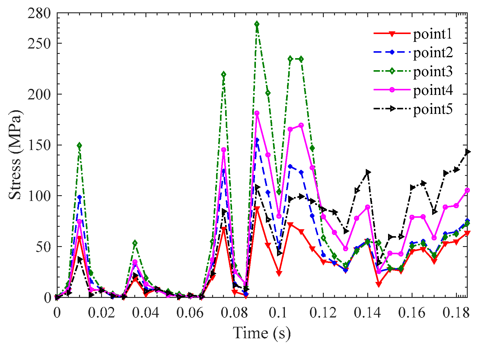
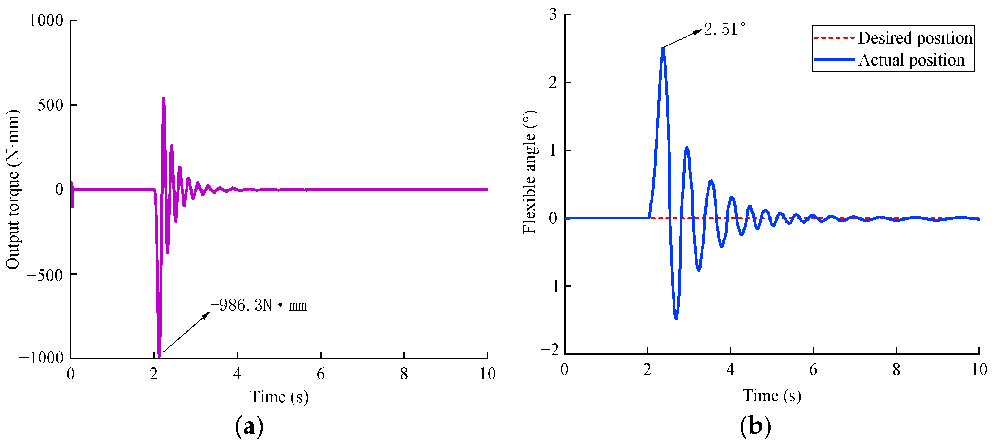
3.5.2. Dynamic Analysis of Shock Resistance Performance

The distance H = 40 mm is obtained by adjusting the sliders during 0–2 s. The input shaft is driven with a rotational speed of 5°/s within 2–10 s. A shock force with 50 N, which is parallel to the tangential direction of the output shaft, is applied on the point that is located at one-third of the shaft, as shown in Figure 27, from 3.1 to 3.2 s. The output torque T h d   and the flexible angle φ j are demonstrated in Figure 29.
As presented in Figure 29a,b, the vibrations of output torque and flexible angle occur after the shock force is applied. At the 3.13 s, the maximum vibration of the output torque is obtained as 985.57 N·mm, and the maximum vibration of the flexible angle is captured as 1.64°. Then, 1.30 s is required by the designed actuator to stabilize the vibrations, suggesting the designed actuators can provide the capability of shock resistance.

4. Discussion

A new rotational variable stiffness actuator with two different mechanisms acting as the passive and active stages of stiffness regulation was designed in the paper. The simulations and experiments showed that the proposed actuator can adjust stiffness in the 35–3286 N·mm/deg range, and the obtained range of the angle difference between the input shaft and output shaft is ±48°, which is wider than previously achieved ranges as in [21,22]. The passive mechanism is the first stage of adjusting the stiffness between the input shaft and the inner shell via the linear motions of springs driven by the rack-and-pinion systems. The active mechanism was devised as the second stage to regulate the stiffness between the internal gear connected to the first mechanism and the output shaft using an active motor. The two pairs of the rack-and-pinion systems of the first mechanism and the two pairs of the planetary gears of the second mechanism were placed side by side to improve the stability and balance of the stiffness regulation process. Two cam-slider mechanisms of the second part, considered the leverage pivot, were symmetrical to achieve the synchronous movements of the two rollers inside the cam.
As shown by the designed mechanisms, simulations, and experiments, effective stiffness regulation was demonstrated with the required strength of the selected materials of the designed actuator. When the unwanted torque caused by unexpected collisions between the input shaft and the external operator or itself occurs in automotive industries, the proposed actuator absorbs or converts it to prevent damaging the output shaft. This mechanism meets the urgent demand for collision safety and intelligence of robots in robot–human collaborative applications. In addition, it can be applied for automatic stiffness adjustment with advanced controllers.
In this study, if the mechanisms are produced with higher precisions and the assembly of them is improved, the stiffness could be achieved more accurately. Due to the lack of control methods, it is difficult to carry out automatic control. In the future, different control methods will be adopted and developed to gain better performances in the stiffness adjustment of designed actuators. And, future studies are planned to test the performance of stiffness regulating in applications of the designed actuator, such as robotic arms and legs.

5. Conclusions

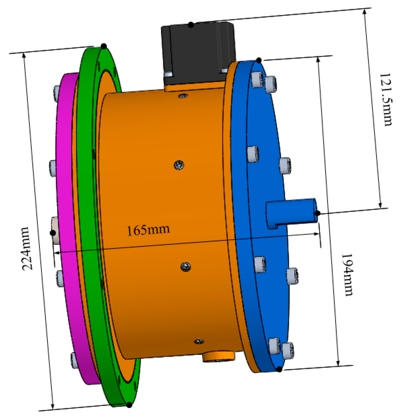
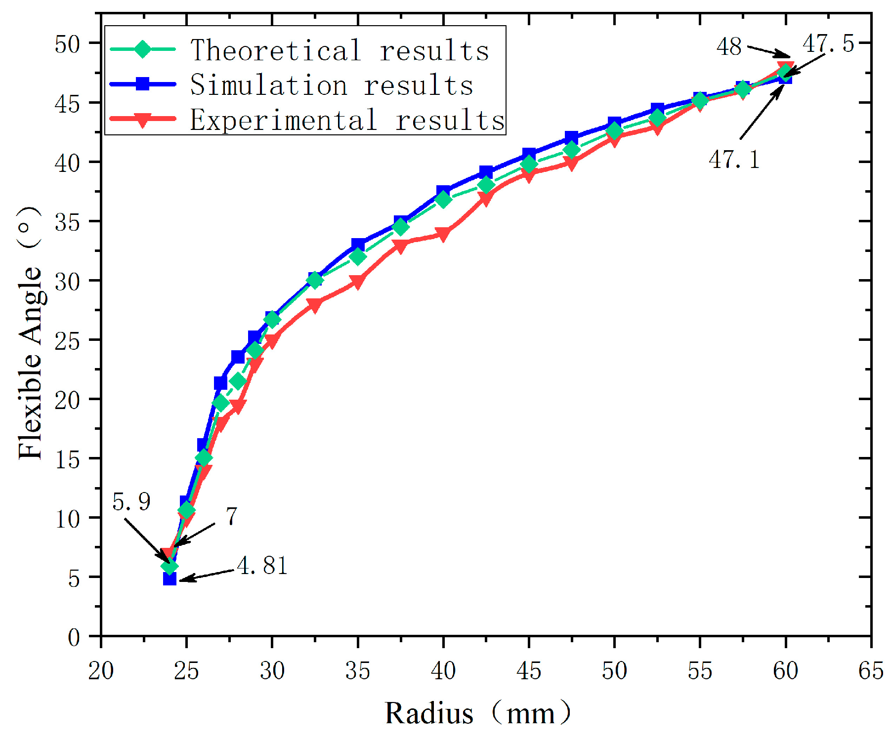
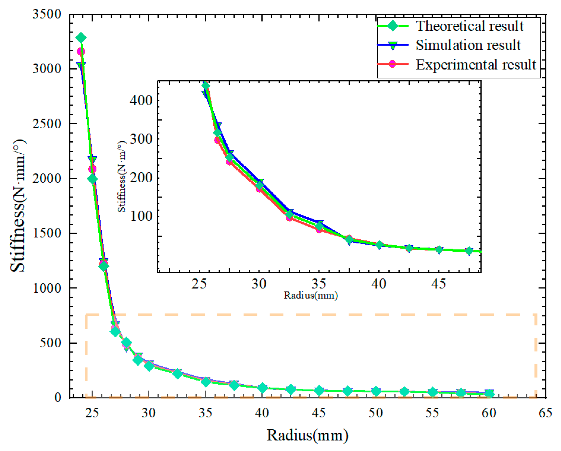
  • The proposed actuator can adjust stiffness in the range of 35–3286 N·mm/deg, and the obtained range of the angle difference between the input shaft and output shaft is ±48°, which is wider than previously achieved ranges as in [21,22]. In addition, the performance of the designed actuator can be used to meet the needs of the collaborative robots according to [34,35];
  • The passive mechanism is connected to the active mechanism to store energy and absorb shocks of the input shaft for achieving hybrid passive–active stiffness regulation;
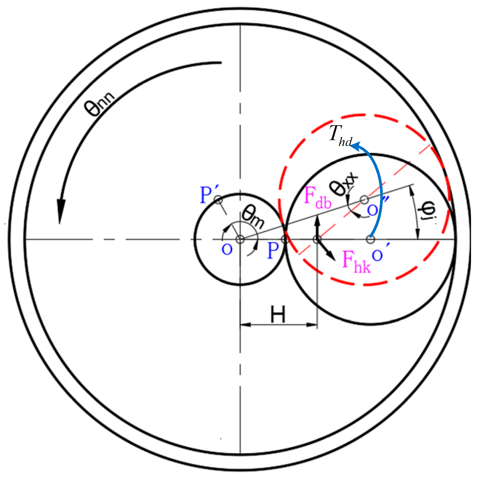
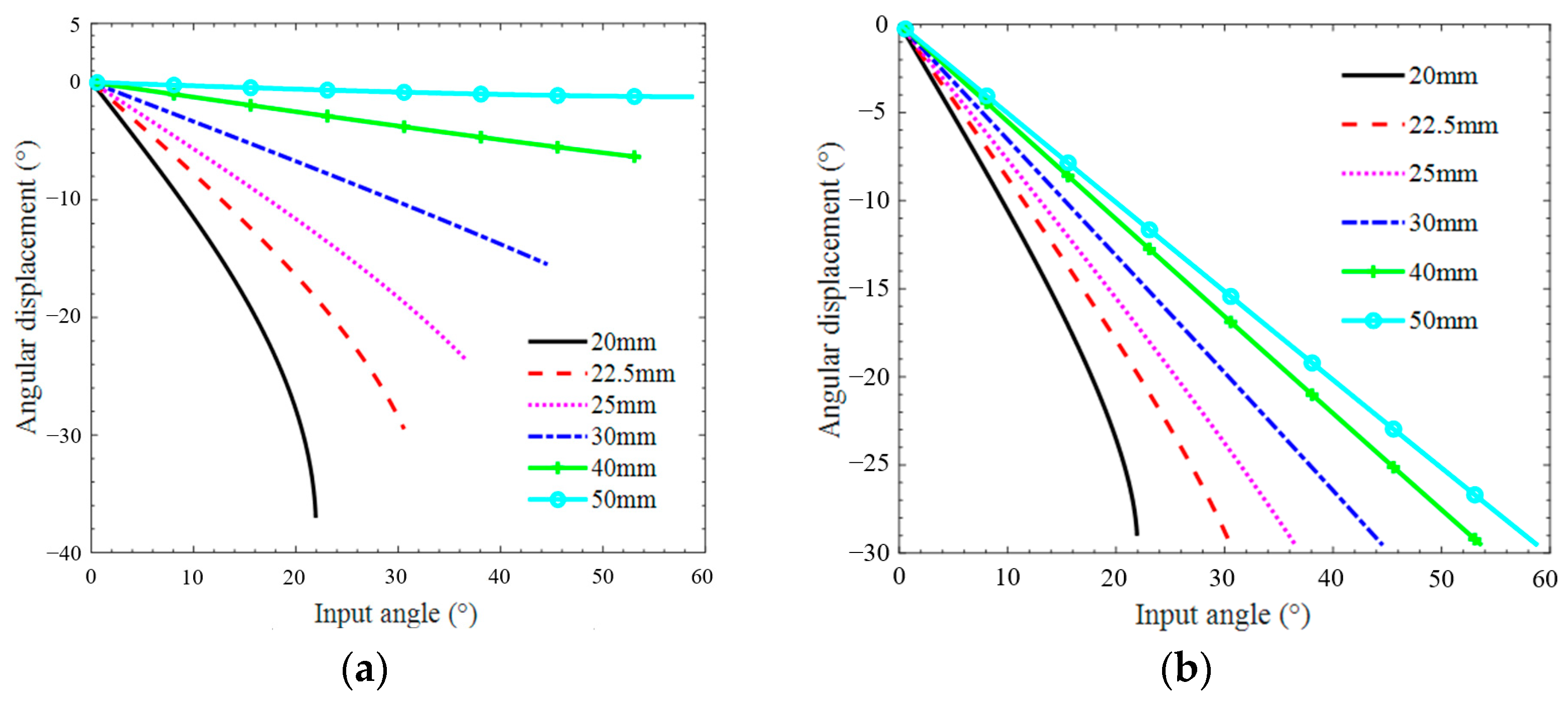
  • It has been observed that the output angle of the internal gear behaves linearly with the input angle of the input shaft when the parameter r is in the range of 25–50 mm. This way, the stiffness can be precisely controlled by adjusting the input angle;
  • The passive and active mechanisms are composites of simple structures and standard motors. This can be easily applied for adjusting rotational stiffness;
  • On the basis of the achieved stiffness range, obtained angle difference, strength analysis, analysis of dynamic movement, and analysis of ball throwing simulations, the proposed actuator can be applied in the future with required performances.

6. Patents

The authors hold a patent related to this work.

Author Contributions

Conceptualization, C.W.; investigation, P.G.; methodology, C.W.; formal analysis, P.G.; software, X.L.; supervision, X.W.; project administration, C.W. and H.Z.; writing—original draft, P.G. and H.W.; writing—review and editing, C.W. All authors have read and agreed to the published version of the manuscript.

Funding

This research was supported by the Program for Science & Technology Innovation Talents in Universities of Henan Province (Grant No. 22HASTIT023) and the National Natural Science Foundation of China (Grant No. 52075500).

Data Availability Statement

Data are contained within the article.

Conflicts of Interest

The authors declare no conflict of interest.

References

  1. Kang, X.; Dai, J. Theoretical Difficulties and Research Progresses of Mechanism Reconfiguration in Mechanisms-Evolution Connotation, Furcation Principle, Design Synthesis and Application of Metamorphic Mechanisms. Chin. J. Mech. Eng. Engl. 2020, 31, 57–71. [Google Scholar]
  2. Rodriguez, A.G.; Rodriguez, N.E.N.; Rodriguez, A.G.G. Design and Validation of a Novel Actuator with Adaptable Compliance for Application in Human-like Robotics. Ind. Robot 2009, 36, 84–90. [Google Scholar] [CrossRef]
  3. Bi, S.; Liu, C.; Zhou, X. Variable Stiffness Actuators: A Review of the Structural Research. Chin. J. Mech. Eng. Engl. 2018, 54, 34–46. [Google Scholar] [CrossRef]
  4. Yao, J.; Chen, X.; Chen, J. Design and Analysis of Soft Manipulator Teleoperation Systems. Chin. J. Mech. Eng. Engl. 2020, 31, 1968–1977. [Google Scholar]
  5. Dagalakis, N.G.; Yoo, J.M.; Oeste, T. Human-robot Collaboration Dynamic Impact Testing and Calibration Instrument for Disposable Robot Safety Artifacts. Ind. Robot. 2016, 43, 328–337. [Google Scholar] [CrossRef] [PubMed]
  6. Wolf, S.; Eiberger, O.; Hirzinger, G. The DLR FSJ: Energy Based Design of a Variable Stiffness Joint. In Proceedings of the IEEE International Conference on Robotics and Automation(ICRA), Shanghai, China, 9–13 May 2011. [Google Scholar]
  7. Liu, B.; Ge, W.; Zhao, D.; Zou, Z.; Li, B. Mechanical Design and Energy Storage Efficiency Research of a Variable Stiffness Elastic Actuator. Int. J. Adv. Robot. Syst. 2020, 17, 5–12. [Google Scholar] [CrossRef]
  8. Gao, C.; Huang, H.; Li, B. Design and Analysis of a Novel Deployable Robotic Grasper. In Proceedings of the IEEE International Conference on Robotics and Biomimetics, Dali, China, 6–8 December 2019. [Google Scholar]
  9. Li, X.; Pan, Y.; Chen, G.; Yu, H. Continuous Tracking Control for a Compliant Actuator with Two-Stage Stiffness. IEEE Trans. Autom. Sci. Eng. 2018, 15, 57–66. [Google Scholar] [CrossRef]
  10. Guo, J.; Tian, G. Conceptual Design and Analysis of Four Types of Variable Stiffness Actuators Based on Spring Pretension. Int. J. Adv. Robot. Syst. 2015, 12, 62–69. [Google Scholar] [CrossRef]
  11. Lavate, M.; Todkar, R.G. Variable Stiffness Actuators: A General Review. Int. J. Eng. Technol. 2015, V4, 201–205. [Google Scholar]
  12. Xu, Y.; Guo, K.; Sun, J.; Li, J. Design and Analysis of a Linear Digital Variable Stiffness Actuator. IEEE Access 2021, 9, 13992–14004. [Google Scholar] [CrossRef]
  13. Moore, R.; Schimmels, J.M.; Zhu, J.; Wang, Y.; Jiang, J. Unidirectional Variable Stiffness Hydraulic Actuator for Load-carrying Knee Exoskeleton. Int. J. Adv. Robot. Syst. 2017, 14, 1–12. [Google Scholar]
  14. Mengacci, R.; Garabini, M.; Grioli, G.; Catalano, M.G.; Bicchi, A. Overcoming the Torque/Stiffness Range Tradeoff in Antagonistic Variable Stiffness Actuators. IEEE/ASME Trans. Mechatron. 2021, 26, 3186–3197. [Google Scholar] [CrossRef]
  15. Xiong, J.; Sun, Y.; Zheng, J.; Dong, D.; Bai, L. Design and Experiment of a SMA-based Continuous-stiffness-adjustment Torsional Elastic Component for Variable Stiffness Actuators. Smart Mater. Struct. 2021, 30, 13–21. [Google Scholar] [CrossRef]
  16. Albu, S.A.; Wolf, S.; Eiberger, O.; Haddadin, S.; Petit, F.; Chalon, M. Dynamic Modelling and Control of Variable Stiffness Actuators. In Proceedings of the IEEE International Conference on Robotics and Automation, Anchorage, AK, USA, 3–5 May 2010. [Google Scholar]
  17. Eiberger, O.; Haddadin, S.; Weis, M.; Albu-Schäffer, A.; Hirzinger, G. On Joint Design with Intrinsic Variable Compliance: Derivation of the DLR QA-joint. In Proceedings of the IEEE International Conference on Robotics and Automation, Anchorage, AK, USA, 3–5 May 2010. [Google Scholar]
  18. Liu, L.; Leonhardt, S.; Bergmann, L.; Misgeld, B.J. Composite Performance of Variable Stiffness Actuator for Exoskeleton Administrated Via Impedance Control and Disturbance Observer. Mech. Mach. Theory 2023, 179, 96–105. [Google Scholar] [CrossRef]
  19. Wang, C.; Sheng, B.; Li, Z.; Sivan, M.; Zhang, Z.Q.; Li, G.Q. A Lightweight Series Elastic Actuator With Variable Stiffness: Design, Modeling, and Evaluation. IEEE/ASME Trans. Mechatron. 2023, 287, 1–10. [Google Scholar] [CrossRef]
  20. Shin, W.; Kim, J. Switchable Compliant Actuator with Fast Stiffness Modulation and Energy Efficient Power Transmission. Micromechatronics 2023, 90, 92–102. [Google Scholar] [CrossRef]
  21. Liu, Y.; Liu, X.; Yuan, Z. Design and Analysis of Spring Parallel Variable Stiffness Actuator based on Antagonistic Principle. Mech. Mach. Theory 2019, 140, 44–58. [Google Scholar] [CrossRef]
  22. Ayoubi, Y.; Laribi, M.A.; Zeghloul, S. V2SOM: A Novel Safety Mechanism Dedicated to a Cobot’s Rotary Joints. Robotics 2019, 8, 18–26. [Google Scholar] [CrossRef]
  23. Shi, Y.; Zhang, X.; Zhang, M. Design and Analysi s of a Active-passive Variable Stiffness Flexible Joint. J. Mech. Eng. Engl. 2018, 54, 55–62. [Google Scholar] [CrossRef]
  24. Wang, W.; Fu, X.; Li, Y. Design and implementation of a variable stiffness actuator based on flexible gear rack mechanism. Robotica 2018, 36, 448–462. [Google Scholar] [CrossRef]
  25. Lee, S.H.; Lee, H.J.; Lee, K.H. A novel Variable Stiffness Scotch Yoke Series Elastic Actuator for Enhanced Functional Stiffness. Microsyst. Technol. 2020, 26, 3395–3402. [Google Scholar] [CrossRef]
  26. Karim, A.; Lindner, P.; Verl, A. Control-based Compensation of Friction and Backlash within Rack and Pinion Drives. Prod. Eng. 2018, 12, 589–596. [Google Scholar] [CrossRef]
  27. Sun, J.; Guo, Z.; Sun, D. Design, modeling and control of a novel compact, energy-efficient, and rotational serial variable stiffness actuator (SVSA-II). Mech. Mach. Theory 2018, 130, 123–136. [Google Scholar] [CrossRef]
  28. Qiu, W.; Yang, F.; Wang, D. Design and Free Vibration Characteristics of Linkage Planetary Gear Trains. J. Braz. Soc. Mech. Sci. 2022, 19, 44–58. [Google Scholar] [CrossRef]
  29. Jafari, A.; Tsagarakis, N.G.; Sardellitti, I. A New Actuator with Adjustable Stiffness Based on a Variable Ratio Lever Mechanism. IEEE/ASME Trans. Mechatron. 2014, 19, 55–63. [Google Scholar] [CrossRef]
  30. Groothuis, S.S.; Rusticelli, G.; Zucchelli, A. The Variable Stiffness Actuator VSA UT-II: Mechanical Design, Modeling, and Identification. IEEE/ASME Trans. Mechatron. 2014, 19, 589–597. [Google Scholar] [CrossRef]
  31. Jafari, A.; Tsagarakis, N.G.; Caldwell, D.G. A Novel Intrinsically Energy Efficient Actuator with Adjustable Stiffness (AWAS). IEEE/ASME Trans. Mechatron. 2013, 18, 355–365. [Google Scholar] [CrossRef]
  32. Shen, Y.; Yang, S.; Liu, X. Nonlinear dynamics of a spur gear pair with time varying stiffness and backlash. Int. J. Mech. Sci. 2004, 23, 179–187. [Google Scholar]
  33. Zhu, P.; Li, Y.; Chen, B. Effects of Zero Time Holding Quenching Temperature on Tempering Microstructure and Mechanical Properties of 40cr steel. In Proceedings of the Chinese Materials Conference (CMC), Chengdu, China, 10–14 July 2019. [Google Scholar]
  34. Zeng, X.; Morrison, T.; Fu, Y. Variable stiffness mechanisms and their applications to collaborative robots. Int. Technol. 2022, 11, 36–47. [Google Scholar]
  35. Pang, G.; Yang, G.; Heng, W. CoboSkin: Soft robot skin with variable stiffness for safer human–robot collaboration. IEEE Trans. Ind. Electron. 2020, 68, 3303–3314. [Google Scholar] [CrossRef]
Figure 1. The designed actuator: (a) variable stiffness actuator, (b) first mechanism, and (c) second mechanism: 1—input shaft; 2—rack-and-pinion system; 3—flange bearing 1; 4—flange bearing with the shell as inner ring; 5—shell; 6—guide plate; 7—stiffness adjustment motor; 8—output shaft; 9—slider; 10—ball screw; 11—internal gear; 12—grooved cam; 13—planetary gear; 14—inner shell; 15—planetary gear frame; 16—guide rod; 17—spring; 18—drive gear; 19—sun gear.
Actuators 12 00450 g001
Figure 2. The first mechanism.
Actuators 12 00450 g002
Figure 3. The second mechanism.
Actuators 12 00450 g003
Figure 4. Dynamic model of second mechanism.
Actuators 12 00450 g004
Figure 5. Flexible output mechanism.
Actuators 12 00450 g005
Figure 6. Simplified system.
Actuators 12 00450 g006
Figure 7. Parameter identification. (a) Identified moments of inertia. (b) Identified damping coefficients.
Actuators 12 00450 g007
Figure 8. Force analysis of second mechanism.
Actuators 12 00450 g008
Figure 9. Analysis of planetary gear train.
Actuators 12 00450 g009
Figure 10. CAD model of the variable stiffness actuator.
Actuators 12 00450 g010
Figure 11. Simulation models established in MATLAB/Simulink. (a) the dynamics simulation model; (b) the simulation model of input mechanism; (c) the simulation model of first mechanism; (d) the simulation model of second mechanism; (e) the simulation model of output mechanism.
Actuators 12 00450 g011aActuators 12 00450 g011b
Figure 12. Experimental platform: 1—the control system; 2—the motor for stiffness adjustment; 3—torque sensor 1; 4—encoder; 5—designed actuator; 6—the main motor; 7—master computer; 8—data transmitter.
Actuators 12 00450 g012
Figure 13. (a) The stress of the rack-and-pinion system of the first mechanism. (b) Stress distribution of the pinion gear.
Actuators 12 00450 g013
Figure 14. (a) Stress distribution of planetary gears, internal gear, and sun gear. (b) Stress distribution of the sun gear.
Actuators 12 00450 g014
Figure 15. Stresses at five nodes in the contact region between the planetary and internal gear.
Actuators 12 00450 g015
Figure 16. (a) The stress of the rollers and the cams. (b) Five nodes of the contact region of the left roller.
Actuators 12 00450 g016
Figure 17. Stresses of the five nodes at the contact region of the left roller.
Actuators 12 00450 g017
Figure 18. Simulation model of the second mechanism.
Actuators 12 00450 g018
Figure 19. (a) Rotation angle of the internal gear θ i g . (b) Output angle of planetary gears θ p g .
Actuators 12 00450 g019
Figure 20. Maximum angle difference θ m a x .
Actuators 12 00450 g020
Figure 21. Actuator stiffness.
Actuators 12 00450 g021
Figure 22. The animation of dynamic movements. (a) original state; (b) state at 2 s; (c) state at 4 s.
Actuators 12 00450 g022aActuators 12 00450 g022b
Figure 23. Angle displacements and output torque (a) angle displacement; (b) output torque.
Actuators 12 00450 g023
Figure 24. The experiment of dynamic movements. (a) original state; (b) state at 2 s; (c) state at 4 s.
Actuators 12 00450 g024
Figure 25. Ball throwing simulations. (a) Simulation of the movement of the ball at 2 s. (b) simulation of the movement of the ball at 2.5 s. (c) simulation of the movement of the ball at 3 s. (d) simulation of the movement of the ball at 3.5 s.
Actuators 12 00450 g025aActuators 12 00450 g025b
Figure 26. Displacements of the ball center. (a) the displacement in the horizontal direction. (b) the displacement in the vertical direction.
Actuators 12 00450 g026
Figure 27. Simulation of shock resistance performance.
Actuators 12 00450 g027
Figure 28. Output torque and flexible angle achieved by static analysis. (a) output torque. (b) flexible angle.
Actuators 12 00450 g028
Figure 29. Output torque and flexible angle achieved by dynamic analysis. (a) output torque. (b) flexible angle.
Actuators 12 00450 g029
Table 1. Gear parameters.
GearsReference Circle Diameter (mm)Number of TeethModuleFace Width (mm)
Gear 1833.0221.510
Rack 281.510
Sun gear 1925.5171.510
Planetary gear 1342.0281.510
Internal gear 11109.5731.510
Table 2. Spring parameters.
Serial NumberParameterValue
1Outer diameter (mm)20.0
2Inner diameter (mm)10.0
3Assembly length (mm)45.0
4Stiffness (N/mm)3
Table 3. Material parameters of gears.
StatsNumerical Value
Modulus of elasticity1.92 ×   10 11 N/m2
Poisson’s ratio0.27
Mass density8000 kg/m3
Tensile strength5.8 ×   10 8 N/m2
Yield strength1.72 ×   10 8 N/m2
Thermal expansion coefficient1.6 ×   10 5 /K
Thermal conductivity16.3 W/(m·K)
Specific heat500 J/(kg·K)
Disclaimer/Publisher’s Note: The statements, opinions and data contained in all publications are solely those of the individual author(s) and contributor(s) and not of MDPI and/or the editor(s). MDPI and/or the editor(s) disclaim responsibility for any injury to people or property resulting from any ideas, methods, instructions or products referred to in the content.

