Article

A Study on Eddy Current Reduction Shape of Single-Phase Claw-Pole Motor

1
Department of Next Generation System Convergence, Gachon University, Seongnam 13120, Republic of Korea
2
Department of Electrical Engineering, Gachon University, Seongnam 13120, Republic of Korea
3
School of Mechanical, Automotive and Robot Engineering, Halla University, Wonju 26404, Republic of Korea
*
Author to whom correspondence should be addressed.
Actuators 2023, 12(12), 451; https://doi.org/10.3390/act12120451
Submission received: 25 October 2023 / Revised: 4 December 2023 / Accepted: 5 December 2023 / Published: 7 December 2023
(This article belongs to the Section High Torque/Power Density Actuators)

Abstract

:
The claw-pole motor, known for its simple structure, is widely used in various fields due to its cost competitiveness. However, a drawback of the fixed-stator-type claw-pole motor is its vulnerability to eddy current losses. Therefore, this paper presents a single-phase claw-pole motor applied as a motor for cooling fans, with the aim of reducing eddy current losses and improving performance based on shape optimization, ultimately resulting in a single-phase claw-pole motor that meets the desired performance. The validity of this approach is verified through 3D finite element analysis (FEA).

1. Introduction

Considering recent fossil fuel depletion and energy regulations, the importance of energy conservation is becoming increasingly prominent. As a result, motor development has also been increasingly focused on high efficiency. High-performance rare-earth permanent magnets, which can enhance the performance of motors in terms of torque, output density, and efficiency, have emerged. This has led to active research in the field of permanent magnet synchronous motors [1]. However, due to rising material costs caused by inflation, an increase in the price of motors has become necessary. As a result, research efforts are actively underway worldwide to produce cost-competitive products by various companies. Because single-phase Drive ICs are more cost-competitive compared to three-phase Drive ICs, many motor applications in household appliances frequently utilize single-phase motors [2]. In pursuit of cost competitiveness, in addition to traditional radial flux motors, claw-pole motors, which employ ring-type permanent magnets, are being researched due to their simple and economical structure.
Motors that offer cost competitiveness often emphasize the importance of streamlining the manufacturing process and reducing material costs. Claw-pole motors, for instance, do not require laminated core plates, and their straightforward structure simplifies the manufacturing process, making them suitable for cost savings [3,4]. Claw-pole motors are fundamentally shaped like claws, and their classification is based on the position of the “claw,” leading to a basic categorization into rotor-type and stator-type, reflecting the attached name according to their core structure. In the case of the rotor-type, it features a structure where the rotor contains coils or permanent magnets that are surrounded by the claws, resembling the shape of the claw enveloping them. On the other hand, the stator-type replaces the traditional motor’s shoes and teeth with the claws. In other words, the claw surrounds the stator coils in this structure. In this context, the advantage is that the coils surrounded by the claw can utilize a ring-type winding configuration based on the shape characteristics of the claw. Specifically, the claw-pole in the rotor is advantageous for making multipolar configurations depending on the number of claws coupled to it, using the slinky lamination method to increase the utilization of electrical steel sheets when manufacturing the stator. However, due to the centrifugal force in the rotor, there is a maintenance drawback, making it necessary to use permanent magnets in the rotor. The brush and commutator structure has a cost disadvantage in maintenance. The materials used in the fixed-type claw-pole motor widely used in alternators for automobiles can be broadly classified into fixed and rotating parts. The stator consists of windings made of copper and a core made of SPCC, while the rotor comprises permanent magnets and a rotor core made of SPCC. Examining the core, a single-phase claw-pole motor does not use laminated steel sheets. This means that when manufacturing the core, there is no need for interlocking and welding for laminating, reducing the costs incurred in the lamination process. Additionally, simplifying the winding structure of the claw-pole motor, which can be seen as concentrating the teeth into one, simplifies the winding process, reducing winding process costs. The fixed-type claw-pole motor is more economical and has a structurally advantageous design for compact lightweight applications, making it suitable for various applications such as optical drives, hard disks, motors for computer peripherals, and drive motors. However, due to the structural characteristics in manufacturing the claw and stator, laminated steel sheets cannot be used, making it highly susceptible to eddy current losses. Recently, there has been active research in applying Soft Magnetic Composite (SMC) materials and 3D printing technology to motors to reduce eddy current losses. However, utilizing 3D printing technology can increase the manufacturing cost of claw-pole, and if claw-pole is produced based on SMC material, it has a significant drawback in terms of stiffness vulnerability. Therefore, a proposed approach is to mitigate eddy current losses by shaping a claw-pole motor without stacking SPCC steel plates, preserving the robust mechanical structure, which is an inherent advantage of claw-pole motors. Therefore, this paper proposes a shape for reducing eddy current losses in a single-phase fixed-type claw-pole motor, targeting its application for cooling the fan motor in microwave ovens. This paper is composed of three main parts. In Section 1, the paper provides an explanation of the operating principles and manufacturing methods of the stator-type claw-pole motor. Section 2 describes the specifications of existing motors used in microwave ovens and conventional ovens and discusses the characteristics of these motors when converted to stator-type claw-pole motors. Section 3 presents a formula for eddy current losses and proposes a shape for reducing eddy current losses through the analysis of the magnetic path and saturation in claw-pole motors. Furthermore, claw-pole motors have a shape that is not constant in the axial direction, unlike typical motors, and the magnetic paths generated in the rotor and stator of claw-pole motors occur in both radial and axial directions. Therefore, the validity of the proposed model was verified using 3D finite element analysis (FEA) [5].

2. Characteristics of Single-Phase Stator Claw-Pole Motor and Driving Principle

Figure 1 provides an explanation of the shape of the stator-type claw-pole motor. In Figure 1a, you can see the structure that includes the rotor, and in Figure 1b, the shape of the stator core is visible. As evident from the figure above, the rotor exhibits a shape similar to that of a surface permanent magnet synchronous motor (SPMSM) with permanent magnets attached to the back yoke. The stator core consists of components resembling claws and a stator back yoke, creating a slotted structure. Within these slots, there is a ring-type winding, and the number of stacked stator cores determines the phase count, resembling a configuration where cans are stacked, hence the term “can stack motor”. In this paper, as it is based on single-phase motors, there is only one stator, as shown in Figure 1b.
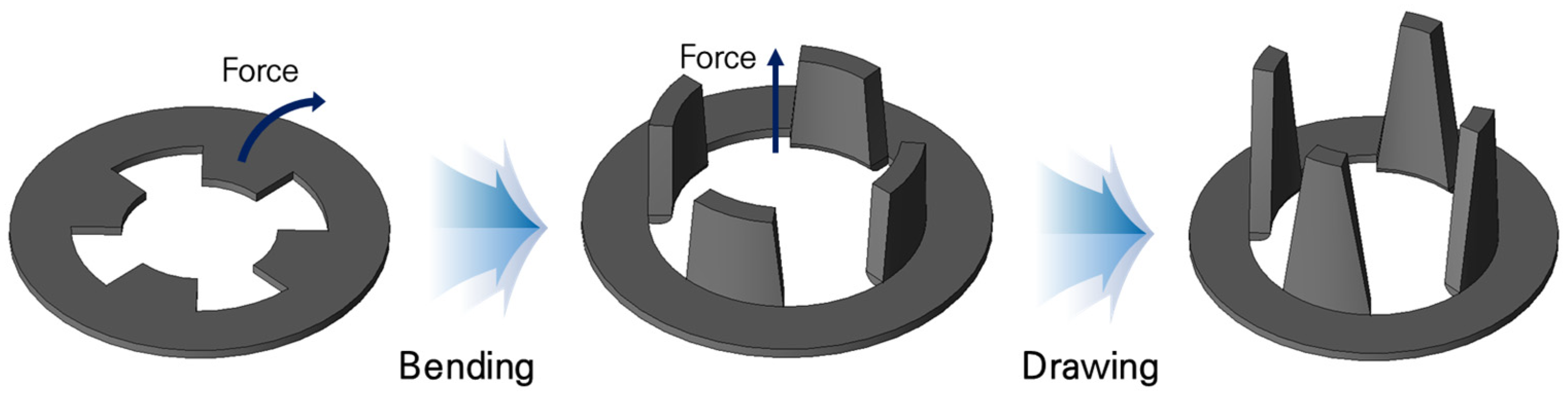
The structure of the stator is notably different from the typical core-type motor, and because of these characteristics, laminated core plates cannot be used. In the manufacturing of claw-pole motor stators, the deep drawing method is employed. Deep drawing is a process that essentially involves pressing a punch onto the sheet metal surface to shape it according to the mold’s form. The process of deep drawing is categorized as “deep” if the depths of pressing reach a diameter of the part which is to be formed [6,7]. Due to this manufacturing process, laminated core plates cannot be used for the stator core. Instead, a material with excellent machinability and formability is required, which is why steel plate cold commercial (SPCC), a type of cold-rolled steel product, is chosen as the material for the stator core. Figure 2 illustrates the stator manufacturing process of a claw-pole motor using the deep drawing method. A part of the stator core is bent and extended using a punch to create the claw shape. However, SPCC is a material that is susceptible to magnetic saturation due to its lower permeability and saturation level compared to electrical steel sheets. In addition, for the non-laminated steel plates, performance varies significantly depending on the thickness. To interpret eddy current losses more accurately, the analysis is conducted based on the fill factor, and to ensure convergence, the analysis is carried out for a minimum of two cycles. The electromagnetic field analysis software used in this paper is Jmag version 22.
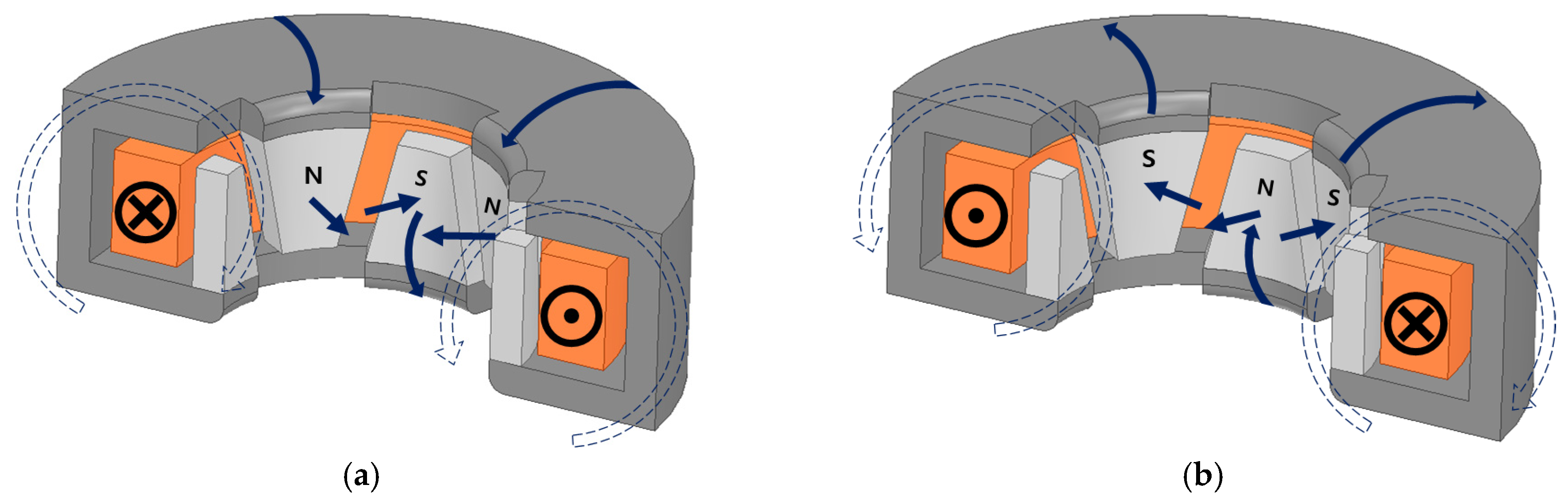
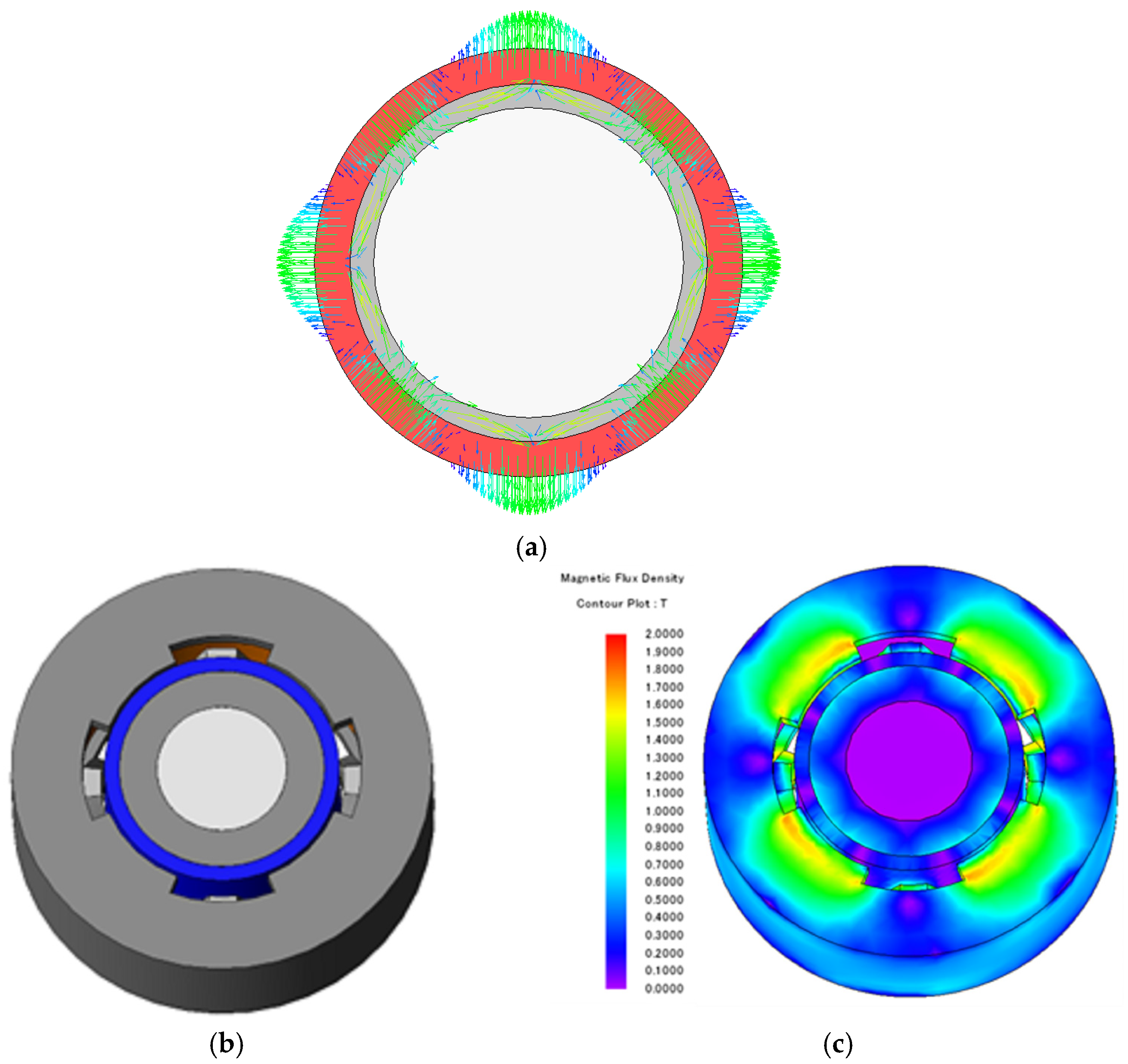
In the case of a single-phase motor, it differs from a three-phase motor by employing a commutator system. While the three-phase motor rotates in accordance with the rotor system during operation, the single-phase motor follows the commutator system. However, the single-phase motor encounters starting issues due to the commutator system. Overcoming the initial counter-torque and rotating in line with the commutator system pose challenges to the starting characteristics compared to the three-phase motor. Even if it successfully generates a torque greater than the counter-torque and starts, the reverse magnetic flux from the commutator system causes the single-phase motor to initially rotate in one direction and then vibrate without ultimately achieving stable operation. To compensate for these starting characteristics, a special structure is required. In this paper, an asymmetric air gap structure is proposed to mitigate the dead point by introducing a phase difference between the cogging torque and the torque. When there is only one pole of permanent magnets on the claw, the magnetic path is as follows: permanent magnet (N)—claw (N)—stator yoke—claw (S)—permanent magnet (S). The magnetic flux entering from the permanent magnet’s south pole exits through the internal path to the permanent magnet’s north pole. When the rotor has moved by half a pitch, and there are permanent magnets with opposite poles on the claw, the magnetic path follows this route: permanent magnet (N)—claw (N)—permanent magnet (S) [8,9,10,11,12] (Figure 3). In this case, it is evident that the magnetic path has a shorter route compared to when one pole of a permanent magnet faces the claw. As a result, due to the ever-changing magnetic path based on the rotor’s position in the claw-pole motor, fluctuations in magnetic stored energy occur. These differences in magnetic stored energy drive the operation of the claw-pole motor.

3. Basic Design of Single-Phase Stator-Type Claw-Pole Motor

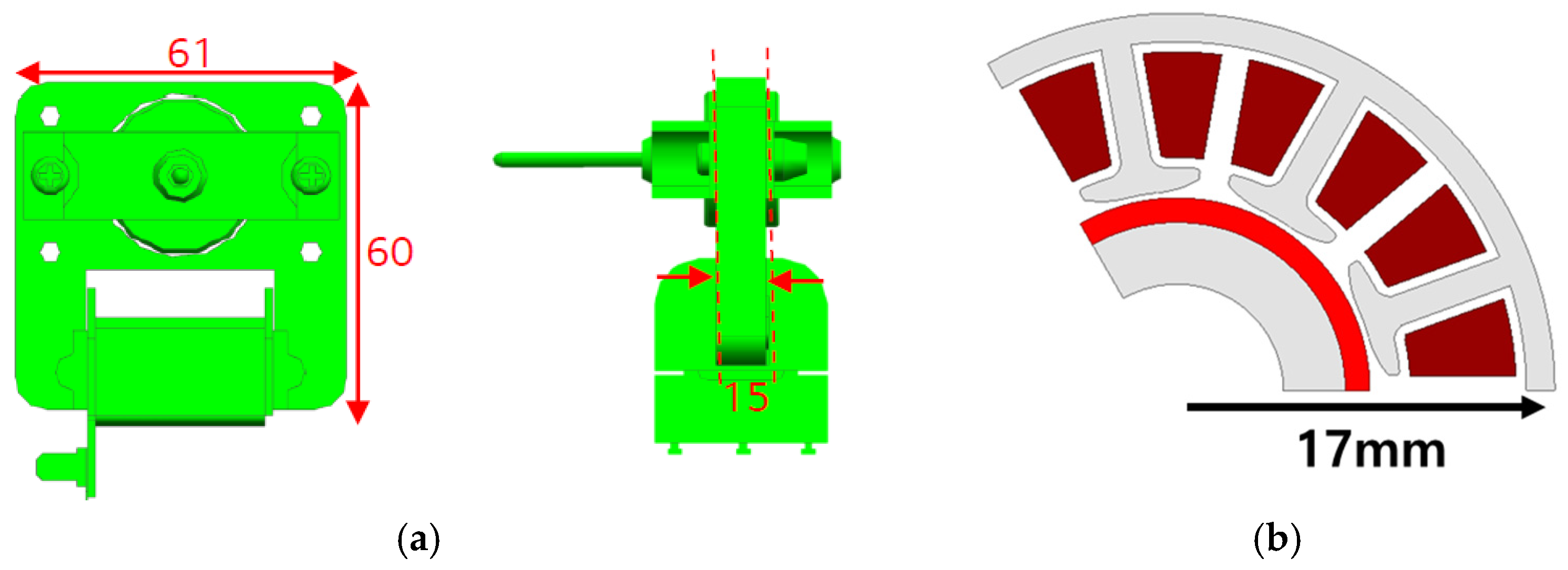
To undertake the basic design of a single-phase claw-pole motor, it is essential to examine the shape and specifications of an existing cooling fan motor, as shown in Figure 4. Figure 4a represents the mass-produced model of the existing cooling fan motor, while Figure 4b is the three-phase model developed for cost savings. In the case of conventional induction motors, the difficulty in speed control led to the use of 11 different motors, resulting in disadvantages for maintenance and upkeep (Table 1). As a solution, research has been conducted to transition to permanent magnet (PM) motors. Therefore, for size constraints, the stacking is 15 mm, the same as the existing inductor, the outer diameter is 39 mm for a motor with a circular shape considering the shaft, and the target power is 5.5 W, the same as the existing cooling fan motor. In this case, the target motor is a three-phase SPMSM (surface permanent magnet synchronous motor) that uses the same permanent magnet as a reference, so we will change it to a single-phase claw-pole motor.
To select the number of poles for the single-phase claw-pole motor, a comparative analysis is carried out for unloaded eddy current losses and back electromotive force (EMF) from 4 poles to 10 poles. For the single-phase claw-pole motor, considering a 1:1 ratio between the poles of permanent magnets and claws, the comparative analysis starts from four poles. It is important to consider that motors with more than 12 poles at the current size face manufacturing challenges, so a comparison of back electromotive force (EMF) is carried out for up to 10 poles under unloaded conditions. In this case, the back electromotive force (EMF) increases up to 10 poles, which is advantageous for performance. However, it is essential to note that the eddy current losses also increase. Based on the results in Figure 5 and Figure 6, models with eight poles or fewer are selected to balance performance and eddy current losses.
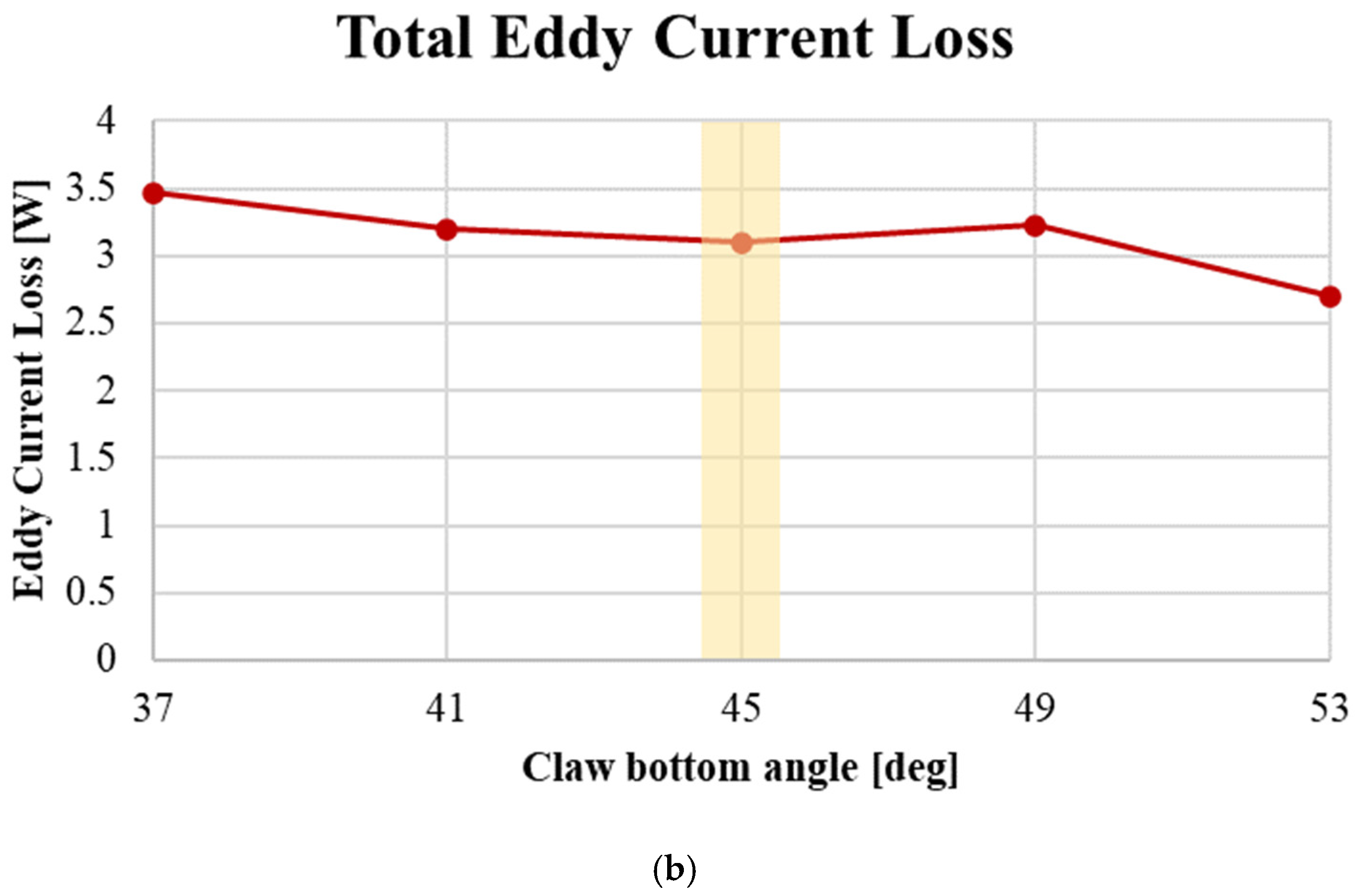
To derive the optimal size of the claw, the no-load performance is analyzed by decreasing and increasing the pole pitch angle by 4 [deg] from 45 [deg], which is the maximum angle of one pole of a permanent magnet on an eight-pole basis. The claw top angle is defined as half of the claw bottom angle; the claw top and claw bottom are shown in Figure 7, and the no-load electromotive force and eddy current losses are shown in Figure 8.
Figure 8 shows that at a pole pitch angle of 45 [deg], the no-load eddy current loss has a sharp change in slope, and the eddy current loss has an inflection point. Based on this, when analyzing based on 45 [deg], the no-load electromotive force decreases by 2 [%], and eddy current loss increases by 3.2 [%] for 41 [deg], which is a decrease of 4 [deg]. For 49 [deg], an increase of 4 [deg], the no-load electromotive force increases by 1.5 [%] and eddy current losses increase by 4.19 [%], so the pole pitch angle of all single-phase claw-pole motor models is selected as the claw bottom angle. In addition, in the case of a motor with a laminated steel plate, the loss characteristics are very different depending on the structure and thickness of the core. Therefore, it should be considered as an eddy current loss calculated based on the conductivity, and the analysis time is very long, so the eddy current loss and air gap asymmetry structure are not considered when performing the tendency analysis. The basic design of a single-phase claw-pole motor within the same size limit as the conventional motor is shown in Figure 9, and the performance is shown in Table 2.
When the motor is the same size as the existing model, it does not meet the target torque of 15 [mN·m]. Therefore, a design is needed to increase the total magnetic loading and total electric loading for torque enhancement. The equation related to total magnetic loading is the same as Equation (1), and the equation related to total electric loading is expressed in Equation (2).
T o t a l   m a g n e t i c   l o a d i n g = 2 p ϕ g   [ T ]
T o t a l   e l e c t r i c   l o a d i n g = I a Z   [ A m p e r e   C o n d u c t o r ]
In Equation (1), p represents the pole pair number, and ϕ g denotes the average gap flux per pole, and in Equation (2), I a represents the phase current, while Z represents the total number of conductors in the stator. As can be seen from the equations, increasing the electrical and magnetic loadings requires an increase in size. Therefore, an analysis of performance characteristics in relation to the increase in stack length and outer diameter is conducted. The shape characteristics are analyzed by adjusting the stack length and outer diameter based on the same volume and magnet usage to design a single-phase claw-pole motor that meets the target performance (Table 3). 
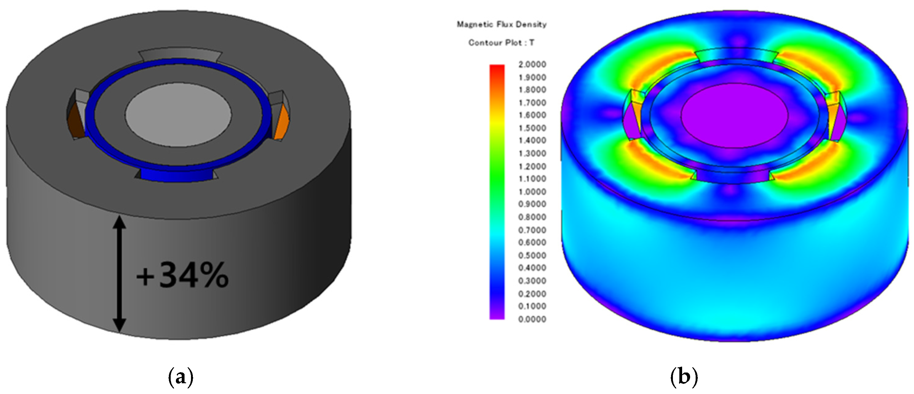
Figure 10 shows the shapes and magnetic saturation densities of each model, with the extent of size increase expressed as a percentage. Figure 8a increased the stack length by 2.3 mm, and Figure 8b increased the outer diameter by 3.32 mm compared to the base model.
Increasing the stack length and outer diameter resulted in an increase in the slot cross-sectional area, and, with a constant slot fill factor, the number of turns also increased. While the model with increased stack length had 15 more turns compared to the model with increased outer diameter, the increased stack length also led to an increase in the effective cross-sectional area for generating torque, resulting in an overall torque increase. Therefore, the design will proceed based on the model with increased stack length. In the case of the single-phase claw-pole motor, there are performance losses due to eddy current losses and uneven air gap, so the analysis will be carried out with performance margins taken into account considering the maximum stack length within the same volume and then analyzing the eddy current losses. 
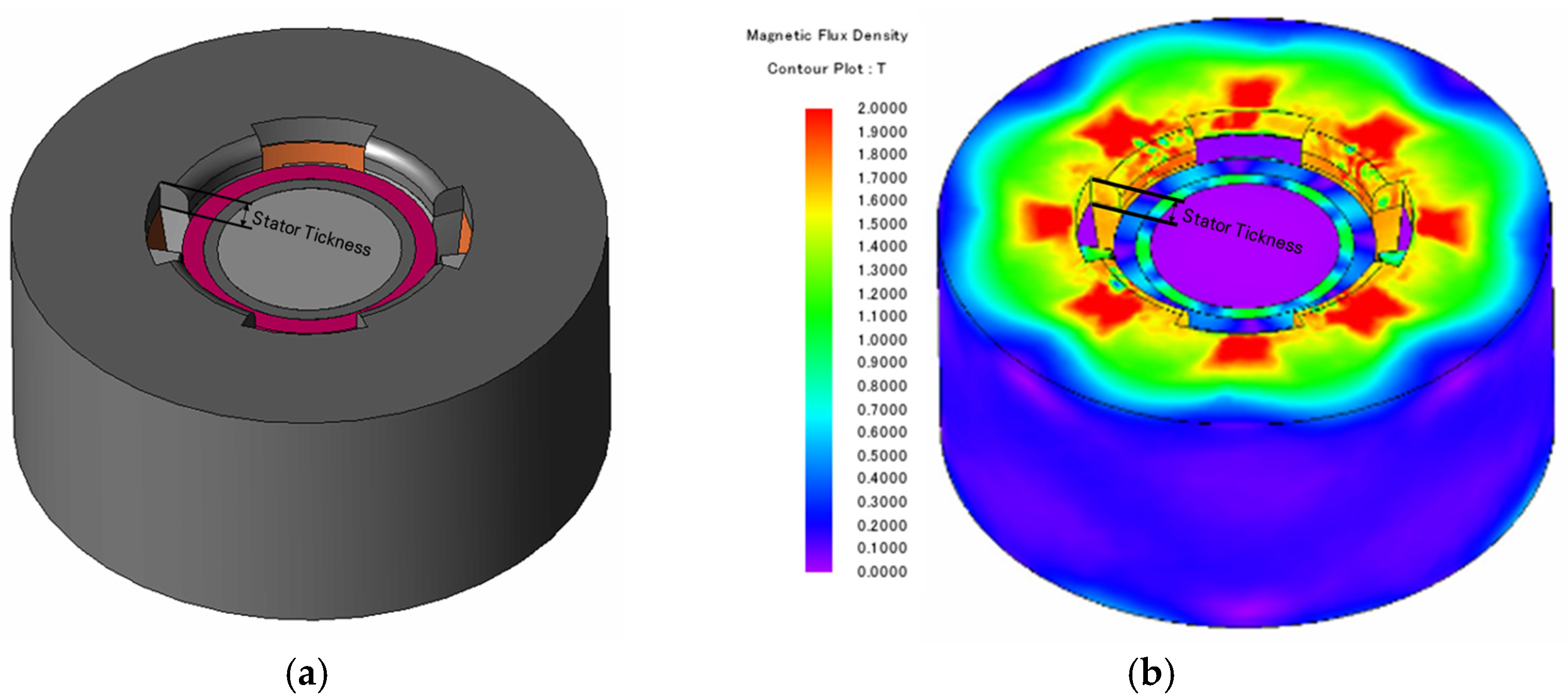
Figure 11 shows the shape and magnetic flux density distribution of the single-phase claw-pole motor with the same stack length as the conventional induction motor. Table 4 displays the performance of the model with the maximum stack length.
The model with the maximum stack length does not meet the target performance when considering the eddy current loss. To achieve the desired performance, it is necessary to design for an increase in the field strength. The sum of the magnetic flux from permanent magnets and the demagnetizing effect caused by the stator current generates the eddy current. To reduce the no-load saturation, electrical loading is maximized to consider the eddy current loss. To maximize the electrical loading, the magnet thickness and the rotor back yoke thickness are minimized. To improve the magnetic flux density, the stator back yoke thickness is increased from the existing 1.5 mm to 1.8 mm. Performance comparisons and analyses are conducted for models with up to eight poles (
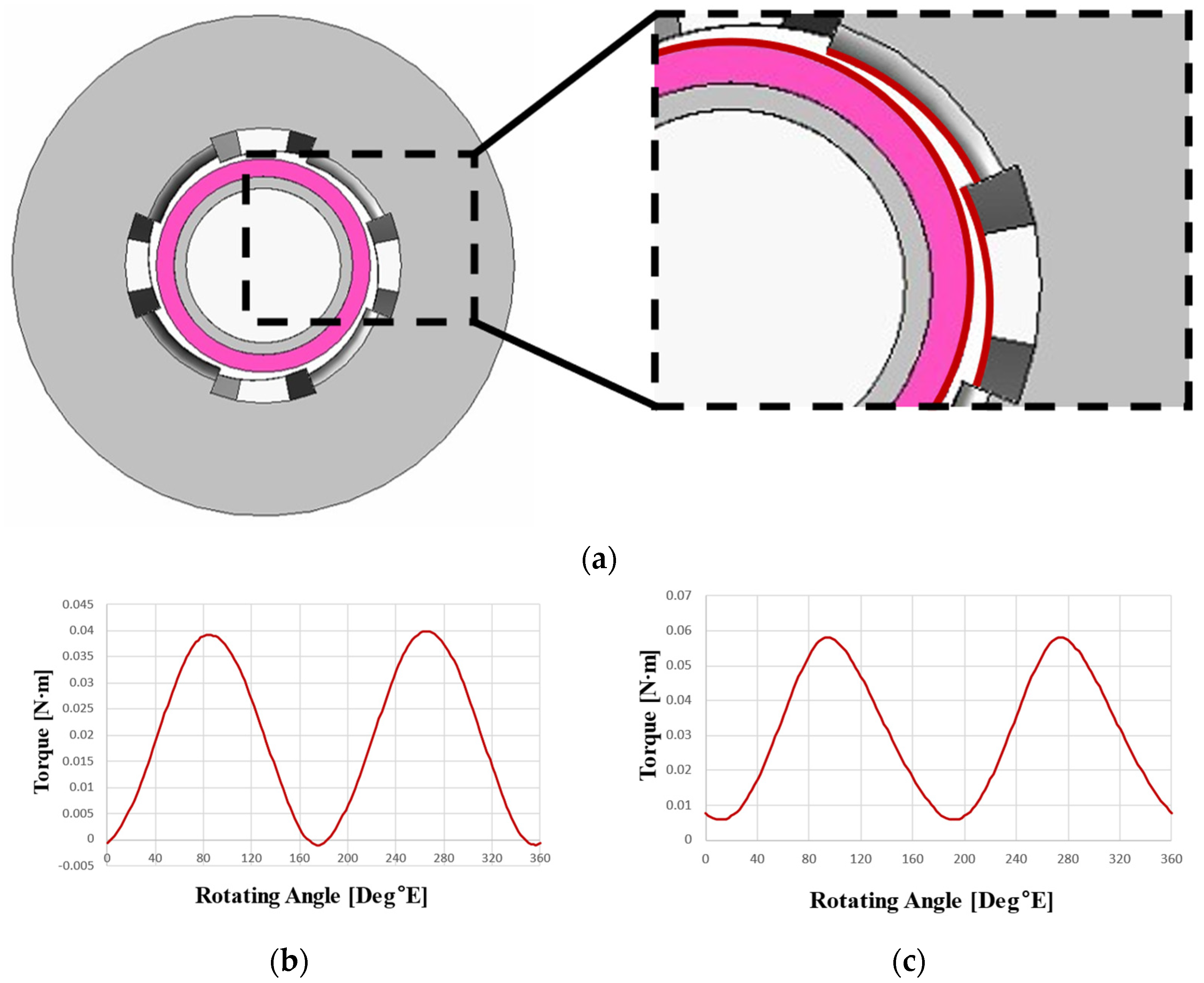
Figure 12). At this point, the wider section of the claw is set to be equal to the pole pitch, while the narrower section is configured to be half of the pole pitch.
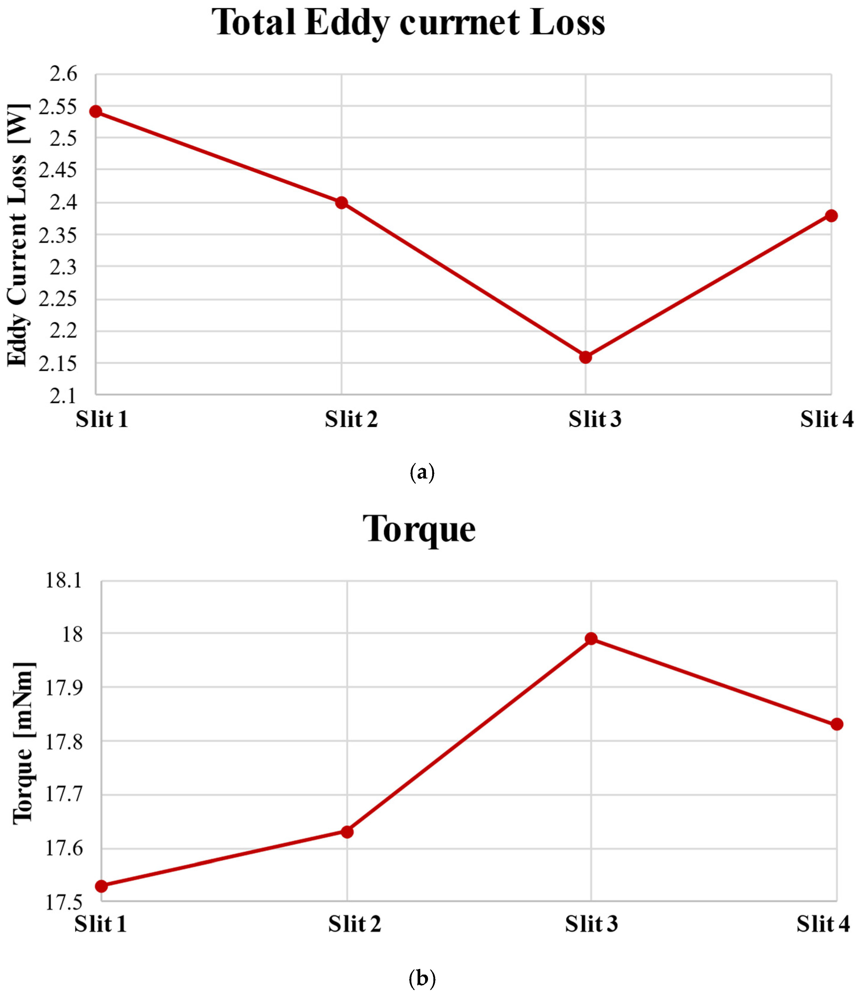
In Table 5, comparing the four poles with the least loss and the eight poles with the most loss, it can be seen that the eddy current loss increases by 64.3%. However, in the single-phase claw-pole motor of this paper, the claw occupies half of the pole pitch below and the upper part as much as the pole pitch, so the smaller the number of poles, the smaller the length of the physical claw. As the number of poles increases, the torque also increases, but once the number of poles exceeds a certain point, the extent of leakage between the poles increases, leading to a decrease in torque. Therefore, based on the table, we can observe that the torque increases by 72.4% when comparing the four-pole configuration. Considering the target performance and performance reduction due to the asymmetric structure of the air gap, the eight-pole model appears to be the most suitable choice. Therefore, we select the eight-pole model to reduce eddy current losses.

4. Reduction in Eddy Current Loss in Single-Phase Stator-Type Claw-Pole Motor Design

4.1. Reduction in Eddy Current Loss Based on the Rotor Under-Hang Model

Most single-phase claw-pole motors, as seen in Figure 13, exhibit a magnetic flux path where magnetic resistance is relatively low, mainly occurring in the claw and the adjacent stator back yoke.
In other words, most of the eddy current losses are directly affected by changes in magnetic flux over time, occurring primarily in the lower portion of the claw with relatively low magnetic resistance and in the stator yoke adjacent to the claw. When considering the reduction in eddy current losses in the single-phase claw-pole motor model, the formula for reducing eddy current losses is similar to Equation (3).
P e = K e B m a x 2 f 2 t 2 V   W
In Equation (3), P e represents eddy current loss, K e is the eddy current factor, B m a x denotes the maximum magnetic flux density, f stands for frequency, t indicates material thickness, and V represents volume. To reduce eddy current losses, the physical length of the rotor’s permanent magnets is reduced to decrease the values of t and V in Equation (3). An under-hang structure is implemented to reduce the rotor’s lamination length by the thickness of the stator back yoke, as illustrated in Figure 14, and the performance specifications are provided in Table 6.
When the rotor under-hang structure was applied, the torque decreased by 1.73% compared to the conventional eight-pole model. However, it was found that total core loss can be reduced by 5.49%. Therefore, using this model as a reference, an asymmetrical air gap structure is applied to shift the cogging torque phase and secure the starting torque. A single-phase motor, unlike a three-phase motor, utilizes a squirrel cage rotor. In the case of a single-phase PM BLDC motor with a uniform air gap, a dead zone occurs where the zero-torque positions of the pull-in torque and cogging torque coincide, rendering it essentially incapable of self-starting [13,14,15,16]. Therefore, an asymmetric air gap shape is applied to shift the zero-point position of the cogging torque and the zero-point torque, allowing for self-starting. To meet voltage limitations, the wire density is increased based on the same current density criterion. The shape and torque phase shift of the single-phase claw-pole motor with an asymmetric air gap structure are depicted in Figure 15, and the performance specifications are presented in Table 7.

4.2. Reduction in Eddy Current Losses Based on Slit Structure

Through Equation (3), it can be observed that the eddy current losses are proportional to the square of the conductor thickness. To reduce eddy current losses, we consider the saturation and magnetic path of the single-phase claw-pole motor. As shown in Figure 16, we insert air insulation into the stator core and reduce the conductor thickness. The eddy current path of the single-phase claw-pole motor is illustrated in Figure 17, showing the application of two air insulations to reduce the conductor thickness to 1/3.
When applying air insulation and the slit structure, it is essential to ensure that it does not interfere with the magnetic path of the stator and account for the core’s saturation. In the claw-pole motor, the eddy current path, as described in Figure 17, is directly influenced by the time rate of change in the magnetic field and is relatively larger in the cross-sectional area, resulting in the highest magnetic resistance in the claw, stator back yoke, and stator areas between the claws. Therefore, identical length and thickness slit structures are applied to these regions. Based on the location of the applied slits for air insulation, different shapes of the single-phase claw-pole motor are proposed, and the eddy current characteristics are examined. Four types of slits, labeled as slit 1, 2, 3, and 4, are compared depending on their application positions. Slit 1 is applied to the claw, slit 2 to the stator yoke adjacent to the claw, slit 3 to the stator between the claws, and slit 4 combines the most effective slit, slit 1, and slit 3 to reduce eddy current losses. By inserting air insulation, it generates the time rate of change in the magnetic field, which is the source of the eddy current. This results in an increase in electrical resistance per unit area, leading to a reduction in eddy current losses. As a result, the stator core can be effectively stacked similar to a conventional radial flux PM motor, and the saturation is depicted in Figure 18.
Through Table 8, it can be observed that the eddy current losses are reduced based on the location of air insulation, resulting in an increase in torque. In the case of the claw-pole model, the performance decrease due to eddy current losses is significant, so it is evident that performance increases when eddy current losses are reduced. Comparing the slit 1, 2, 3, and 4 models to the models with asymmetrical air gaps and under-hang application in Table 8, each of them show a reduction in eddy current losses by 1.17%, 6.61%, 15.95%, and 7.39%, respectively, with an increase in torque by 1.88%, 2.44%, 4.53%, and 3.63%, as illustrated in Figure 19.
In the case of slit 4, even though it combines two of the most effective slit models, the increase in the number of air insulations leads to an increase in stator saturation due to the reduction in the cross-sectional area of the magnetic path. As a result, it is evident that the eddy current losses increase compared to the slit 3 model. Therefore, when applying air insulation, it is essential to consider the magnetic path and saturation. Furthermore, when comparing the eddy current losses of the eight-pole model from Table 4 with the most effective slit 3 model in reducing eddy current losses, it is confirmed that the slit 3 model reduces eddy current losses by 46.15%. This has resulted in the derivation of a model that satisfies the target output of 5.5 W based on 3D FEA.

5. Conclusions

In this paper, a motor for a three-phase cooling fan was changed to a single-phase claw-pole motor to meet the size limitations of the existing inductor. To compensate for the disadvantage of the difficult maintenance and repair of the inductor, it was replaced by a three-phase BLDC, so a three-phase BLDC was selected as the target motor and the basic design was carried out. Most of the eddy current losses occur in the lower part of the claw and the stator yoke adjacent to the claw, where the magnetic resistance is relatively small and directly receives the change in magnetic flux with respect to time, so in consideration of this, the eddy current losses were reduced by relatively decreasing t and V in the equation of eddy current loss by applying a rotor under-hang structure. The eddy current reduction rate was reduced by 5.49% compared to the torque reduction rate of 1.73%, and a reasonable result was obtained. Air insulation was inserted to further reduce eddy current losses. In the case of the slit 4 model, even though the slit 1 and slit 3 models were combined, the eddy current loss increased due to the increase in stator saturation due to the decrease in the cross-sectional area of the flux path as the number of slits increased. Therefore, the slit 3 model is the most effective in reducing eddy current losses as the torque increased by 4.53% and the eddy current losses were reduced by 15.95% compared to before inserting air insulation. A model satisfying the target performance was derived and validated through 3D FEA.

Author Contributions

Conceptualization, W.-H.K.; methodology, N.-R.J.; software, Y.-S.L.; validation, N.-R.J.; formal analysis, Y.-S.L.; investigation, H.-J.P.; resources, N.-R.J.; data curation, K.-S.K.; writing—original draft preparation, N.-R.J.; writing—review and editing, H.-J.P. and D.-H.J.; visualization, K.-S.K. and D.-H.J.; supervision, W.-H.K. All authors have read and agreed to the published version of the manuscript.

Funding

This research was partly supported by the Korea Institute of Energy Technology Evaluation and Planning (KETEP) grant funded by the Korea government (MOTIE) (20214000000060, Department of Next Generation Energy System Convergence based on Techno-Economics—STEP) and, in part, this work was supported by the Gachon University research fund of 2021 and in part by the Basic Science Research Program through the National Research Foundation of Korea (NRF) funded by the Ministry of Education (No. NRF-2022R1I1A3068863).

Data Availability Statement

Data are contained within the article.

Conflicts of Interest

The authors declare no conflict of interest.

References

  1. Rahman, M.A.; Little, T.A. Dynamic Performance Analysis of Permanet Magnet Synchronous Motors Magnet Synchronous Motors. IEEE Trans. Power Appar. Syst. 1984, 6, 1277–1282. [Google Scholar] [CrossRef]
  2. Lee, J.-H.; Jung, S.-Y. Noise Reduction Design with Trapezoidal Back-EMF and Asymmetric Air-Gap for Single-Phase BLDC Refrigerator Cooling Fan Motor. Energies 2021, 14, 5467. [Google Scholar] [CrossRef]
  3. Zhang, Y.; Gao, M.; Wang, L.; Zhang, X.; Xu, M.; Hu, W.; Wang, L. Study of Electromagnetic Characteristics of Brushless Reverse Claw-Pole Electrically Excited Generators for Automobiles. Energies 2023, 16, 2573. [Google Scholar] [CrossRef]
  4. Lim, S.-B.; Jung, D.-S.; Kim, K.-C.; Koo, D.-H.; Lee, J. Characteristic Analysis of Permanent-Magnet-Type Stepping Motor With Claw Poles by Using 3 Dimensional Finite Element Method. IEEE Trans. Magn. 2007, 43, 2519–2521. [Google Scholar] [CrossRef]
  5. Jung, D.-S.; Lim, S.-B.; Lee, S.G.; Lee, J. A study on the improvement of static characteristic in claw poled permanent magnet stepping motor. In Proceedings of the 2006 12th Biennial IEEE Conference on Electromagnetic Field Computation, Miami, FL, USA, 30 April–3 May 2006; p. 120. [Google Scholar] [CrossRef]
  6. Martawirya, Y.Y.; Raharno, S.; Sadono, D. Preliminary study of a deep drawing process modelling for AL-5083 aluminium material. In Proceedings of the 2014 International Conference on Electrical Engineering and Computer Science (ICEECS), Kuta, Bali, Indonesia, 24–25 November 2014; pp. 315–320. [Google Scholar] [CrossRef]
  7. Shi, S. The Research of Feedback-Feedforward Iterative Learning Control in Hydrodynamic Deep Drawing Process. In Proceedings of the 2015 14th International Symposium on Distributed Computing and Applications for Business Engineering and Science (DCABES), Guiyang, China, 18–24 August 2015; pp. 423–426. [Google Scholar] [CrossRef]
  8. Ibala, A.; Masmoudi, A. 3D FEA based feature investigation of a claw pole alternator with DC excitation in the stator. In Proceedings of the 2010 7th International Multi- Conference on Systems, Signals and Devices, Amman, Jordan, 27–30 June 2010; pp. 1–6. [Google Scholar] [CrossRef]
  9. Leitner, S.; Kulterer, T.; Gruebler, H.; Muetze, A. Characterization of the Thermal Performances of Low-Cost Sub-Fractional Horsepower BLDC Claw-Pole Motor Designs. In Proceedings of the 2020 IEEE Energy Conversion Congress and Exposition (ECCE), Detroit, MI, USA, 11–15 October 2020; pp. 4269–4275. [Google Scholar] [CrossRef]
  10. Dong, Y.; Li, X.; Wang, X.; Lu, K.; Feng, X. Design and Analysis of Electric-Excitation Claw-Pole Field-Modulated Machine Considering Effective Harmonics. In Proceedings of the 2022 IEEE Energy Conversion Congress and Exposition (ECCE), Detroit, MI, USA, 9–13 October 2022; pp. 1–6. [Google Scholar] [CrossRef]
  11. Elloumi, D.; Ibala, A.; Rebhi, R.; Masmoudi, A. Lumped Circuit Accounting for the Rotor Motion Dedicated to the Investigation of the Time-Varying Features of Claw Pole Topologies. IEEE Trans. Magn. 2015, 51, 8105108. [Google Scholar] [CrossRef]
  12. Zhang, W.; Xu, Y.; Sun, M. Design of a Novel Claw Pole Transverse Flux Permanent Magnet Motor Based on Hybrid Stator Core. IEEE Trans. Magn. 2021, 57, 8104705. [Google Scholar] [CrossRef]
  13. Fazil, M.; Rajagopal, K.R. A Novel Air-Gap Profile of Single-Phase Permanent-Magnet Brushless DC Motor for Starting Torque Improvement and Cogging Torque Reduction. IEEE Trans. Magn. 2010, 46, 3928–3932. [Google Scholar] [CrossRef]
  14. Park, Y.-U.; Cho, J.-H.; Kim, D.-K. Cogging Torque Reduction of Single-Phase Brushless DC Motor With a Tapered Air-Gap Using Optimizing Notch Size and Position. IEEE Trans. Ind. Appl. 2015, 51, 4455–4463. [Google Scholar] [CrossRef]
  15. Jin, B.-P.; Wang, H.; Li, J.-B.; Wu, Z.-W. High Precision Servo Control of Single-phase BLDC motor based on Fuzzy self-tuning PID. In Proceedings of the 2022 International Symposium on Control Engineering and Robotics (ISCER), Changsha, China, 18–20 February 2022; pp. 38–41. [Google Scholar] [CrossRef]
  16. Chiu, C.-L.; Chen, Y.-T.; Jhang, W.-S. Properties of Cogging Torque, Starting Torque, and Electrical Circuits for the Single-Phase Brushless DC Motor. IEEE Trans. Magn. 2008, 44, 2317–2323. [Google Scholar] [CrossRef]
Figure 1. Shape of the single-phase stator-type claw-pole motor: (a) overall shape; (b) stator core shape.
Actuators 12 00451 g001
Figure 2. The concept of manufacturing the claw using deep drawing processing.
Actuators 12 00451 g002
Figure 3. Claw polarity and magnetic field direction in a stator-type claw-pole motor based on the current direction: (a) clockwise current input; (b) counterclockwise current input.
Actuators 12 00451 g003
Figure 4. Existing cooling fan motor shape and size specifications: (a) single-phase induction motor shape; (b) 3-phase motor shape.
Actuators 12 00451 g004
Figure 5. Comparative analysis of back electromotive force (EMF) for different numbers of poles under unloaded conditions.
Actuators 12 00451 g005
Figure 6. Comparative analysis of eddy current losses for different numbers of poles.
Actuators 12 00451 g006
Figure 7. Define claw top and bottom for a single-phase claw-pole motor.
Actuators 12 00451 g007
Figure 8. Performance comparison by claw bottom angle: (a) no-load electromotive force; (b) eddy current loss.
Actuators 12 00451 g008aActuators 12 00451 g008b
Figure 9. Identical size model to the existing 3-phase cooling fan motor: (a) PM magnetization (b) shape; (c) magnetic flux density.
Actuators 12 00451 g009
Figure 10. Model with increased stack length and outer diameter: (a) model with increased stack length shape; (b) model with increased stack length magnetic saturation density; (c) model with increased outer diameter shape; (d) model with increased outer diameter magnetic saturation density.
Actuators 12 00451 g010
Figure 11. Shape and magnetic flux saturation density of the maximum stacking length model: (a) stacking length maximum model shape; (b) stacking length maximum model flux saturation density.
Actuators 12 00451 g011
Figure 12. Shape and magnetic flux saturation density of a single-phase claw-pole motor: (a) 4-pole shape; (b) magnetic flux saturation density of 4-pole model; (c) 6-pole shape; (d) magnetic flux saturation density of 6-pole model; (e) 8-pole shape; (f) magnetic flux saturation density of 8-pole model.
Actuators 12 00451 g012
Figure 13. Saturation density and magnetic path in the single-phase claw-pole motor stator: (a) stator saturation flux density; (b) magnetic path.
Actuators 12 00451 g013
Figure 14. The model shape and magnetic flux saturation density of the rotor under-hang application: (a) rotor under-hang model shape; (b) rotor under-hang model magnetic flux saturation density.
Actuators 12 00451 g014
Figure 15. Asymmetrical air gap structure applied configuration and torque waveforms: (a) asymmetrical air gap structure shape; (b) conventional torque waveform; (c) torque waveform when the asymmetrical air gap structure is applied.
Actuators 12 00451 g015
Figure 16. Conceptual diagram of air insulation application: (a) without air insulation; (b) with air insulation.
Actuators 12 00451 g016
Figure 17. Eddy current path in the single-phase claw-pole motor.
Actuators 12 00451 g017
Figure 18. Magnetic saturation of the single-phase claw-pole motor with air insulation applied in different locations: (a) slit 1; (b) slit 2; (c) slit 3; (d) slit 4.
Actuators 12 00451 g018
Figure 19. Performance analysis based on the slit models: (a) eddy current loss comparison; (b) torque comparison.
Actuators 12 00451 g019
Table 1. Performance specifications by type of existing motor.
ParameterValueUnit
ModelSingle-phase inductor3phase BLDC-
Size61 × 60 × 1534 × 11.2mm
Power55W
Speed29502950r/min
Torque1515mN·m
Current density7.967.96Arms/mm2
Table 2. Performance of a claw-pole motor with the same specifications as a conventional three-phase BLDC motor.
ParameterValueUnit
Power3.63W
Speed2950r/min
Torque12.38mN·m
Current0.486Arms
Current density7.96Arms/mm2
Voltage13.57V
Number of turns129-
Table 3. Performance comparison of the increased stack length model and increased outer diameter model.
ParameterValueUnit
ModelIncreased stack lengthIncreased outer
diameter
-
Power5.555.5W
Speed29502950r/min
Torque18.618.43mN·m
Current0.4860.486Arms
Current density7.967.96Arms/mm2
Voltage21.5322.02V
Number of turns182197-
Table 4. Performance of a single-phase claw-pole motor with maximum stacking length.
ParameterValueUnit
ModelMaximum stacking length-
Power1.79W
Speed2950r/min
Torque5.81mN·m
Current0.486Arms
Current density7.96Arms/mm2
Voltage20.54V
Number of turns216-
Claw eddy current loss1.35W
Stator back yoke eddy current loss2.41W
Table 5. Performance comparison of single-phase claw-pole motor by pole numbers.
ParameterValueUnit
Model4 Poles6 Poles8 Poles-
Rotor and stator coreSPCC-
MagnetHMG-12L-
Outer diameter34mm
Stack length15mm
Claw bottom angle906045deg
Power3.324.65.72W
Speed295029502950r/min
Torque10.7414.8918.52mN·m
Current0.4860.4860.486Arms
Current density7.967.967.96Arms/mm2
Voltage23.7931.5738.05V
Number of turns398398398-
Claw eddy current loss0.821.11.31W
Stator back yoke eddy current loss1.622.122.7W
Table 6. Specifications of the rotor under-hang application model performance.
ParameterValueUnit
ModelRotor under-hang application-
Power5.61W
Speed2950r/min
Torque18.2mN·m
Current0.486Arms
Current density7.96Arms/mm2
Voltage37.66V
Number of turns398-
Claw eddy current loss1.3W
Stator back yoke eddy current loss2.49W
Table 7. Performance specifications of the asymmetrical air gap applied model.
ParameterValueUnit
ModelAsymmetrical air gap
Application
-
Power5.32W
Speed2950r/min
Torque17.21mN·m
Current1.76Arms
Current density7.96Arms/mm2
Voltage9.33V
Number of turns110-
Claw eddy current loss0.86W
Stator back yoke eddy current loss1.71W
Table 8. Performance specifications based on the air insulation location in the single-phase claw-pole motor.
ParameterValueUnit
ModelSlit 1Slit 2Slit 3Slit 4-
Power5.415.455.565.51W
Speed2950295029502950r/min
Torque17.5317.6317.9917.83mN·m
Torque increment ratio1.882.444.533.36%
Current1.761.761.761.76Arms
Current density7.967.967.967.96Arms/mm2
Voltage9.549.419.59.44V
Number of turns110110110110-
Claw eddy current loss0.710.840.860.68W
Stator back yoke eddy current loss1.831.561.31.7W
Disclaimer/Publisher’s Note: The statements, opinions and data contained in all publications are solely those of the individual author(s) and contributor(s) and not of MDPI and/or the editor(s). MDPI and/or the editor(s) disclaim responsibility for any injury to people or property resulting from any ideas, methods, instructions or products referred to in the content.

