Article

Electromechanical Actuator-Based Solution for a Scissor Lift

1
Institute of Machine Tools and Production Engineering, Faculty of Mechanical Engineering, Lodz University of Technology, 90-924 Lodz, Poland
2
Innovative Hydraulics and Automation (IHA) Lab, ATME, Faculty of Engineering and Natural Sciences, Tampere University, 6, 33720 Tampere, Finland
*
Author to whom correspondence should be addressed.
Actuators 2023, 12(10), 394; https://doi.org/10.3390/act12100394
Submission received: 11 August 2023 / Revised: 16 October 2023 / Accepted: 19 October 2023 / Published: 21 October 2023
(This article belongs to the Special Issue Innovative and Intelligent Actuation for Heavy-Duty Applications)

Abstract

:
Electrification and hybridization in non-road mobile machinery have attracted considerable attention in recent years. Normally, these green solutions concentrate on drivetrains, slowly penetrating to the implements or, as they are commonly known, working hydraulics. The primary difficulties associated with drivetrains were successfully addressed through the implementation of electric solutions and the utilization of hydraulic configurations. However, existing hydraulics solutions are typically challenged by innovative pure electromechanical solutions to perform the same work. Therefore, the purpose of this study is to illustrate the impact of replacing a conventional hydraulic topology with an electromechanical actuator (EMA) solution. This paper presents a case study of the electrification of a scissor lift, which was evaluated by simulation and experimental works from an energy perspective. The simulation study demonstrated the energy consumption and power requirements in conventional hydraulic (i.e., non-efficient in comparison with advanced systems) and EMA-based topologies for a single lifting cycle. Finally, an average of 35–50% of the consumed energy was saved, which is confirmed based on a completed simulation study case for the scissor lift application.

1. Introduction

A strong electrification trend is penetrating the heavy-duty mobile machinery industry. The motivation is to mitigate or slow down climate change and meet enforced related regulations [1,2]. This can be clearly seen from the recent BAUMA construction fair in Munich, Germany in October 2022. Limited examples of large electric-hybrid heavy-duty mobile machinery (over 10 tonnes) were presented for audience review, where an Internal Combustion Engine (ICE) with a coupled generator was utilized as a range extension option. In addition, a sufficient albeit not impressive amount of small and medium battery-based electric heavy-duty mobile machinery was presented. This machinery was mostly excavators, wheel loaders, and asphalt rolling machines. For instance, Caterpillar, Hitachi, and Hyundai launched small and medium machinery products during BAUMA 2022; however, examples of large mobile machinery, such as Volvo and Yanmar, were only displayed as conceptual vehicles. Based on these examples, it is clear that Original Equipment Manufacturers (OEMs) are much more experienced with the electrification of powertrains in small- and medium-sized machines. This is presumably due to the sizing of the power source (e.g., batteries) which is dependent on the mechanical input requirement from working hydraulics.
Given these constraints, the expansion of electrification to large heavy-duty mobile machines in an economically viable way requires gains in energy efficiency. In addition, focusing on energy efficiency in the context of small- and medium-sized machines would allow electrification to be expanded further from powertrains to working hydraulics. The result enables an optimization of the battery sizing, which in turn makes these vehicles more attractive from an economical point of view as their productivity/range can be increased.
Furthermore, several concepts which can support energy efficiency and enable green changes in non-road mobile machinery (NRMM) have been proposed already by academia and have slowly started to penetrate industry. Fassbender et al. summarized the current division of research trends in mobile hydraulics for off-road machinery [3]. Major academy-proposed concepts are hydraulics based, such as independent metering, digital hydraulics, or pump control instead of valve-control systems, which could all be further divided into sub-concepts.
Independent metering enables control freedom and reduces metering losses by utilizing multiple simple valves instead of a single complex multi-way valve. A detailed review and highlights of development trends related to independent metering were presented by Abuowda et al. in [4]. In contrast with independent metering, digital hydraulics uses components with discrete states (i.e., valves, pumps, motors, or cylinders) to achieve semi-continuous variable behavior for the control of hydraulic actuators. A state-of-the-art review of digital hydraulics was presented in [5] by Linjama et al.
Industrial examples of energy-efficient components and subsystems include the Artemis digital pump manufactured by Danfoss from 2021 [6], the high-efficiency hydraulic pump/motor by INNAS [7] manufactured by Bucher hydraulic [8], and the digital cylinder package Norrdigi by Norrhydro [9].
Alternative approaches to utilizing pure hydraulics can be considered electrohydraulic/electrohydrostatic solutions which are at the core of zonal or decentralized power distribution systems [10].
An alternative solution from a control method perspective is an electrohydraulic actuator (EHA). In EHAs, the actuator velocity can be controlled directly with an electric motor. In the basic setup, the motor and pumps are connected directly without flow-throttling valves. This provides high system energy efficiency, achieving even 65% in limited working conditions [11], by means of reducing the required peak torque of the electric motor by 52%. In [12], energy savings were achieved by means of combining multi-pressure system elements, including hydraulic accumulators and the EHAs.
The most radical solution compared to hydraulics would be an electromechanical actuator (EMA), where hydraulics is abandoned. In the EMA, the rotary motion of the electric motor is converted into linear displacement. The efficiencies of EMAs vary from 80 to 90% [13], and it can be the basis of innovation of new designs and system topologies.
In [14], guidance for the dimensioning of an EMA and EHA was provided based on a studied single boom crane. As a result, the EMA solution is expected to demonstrate better controllability (due to drive stiffness) and energy efficiency compared to conventional valve-controlled solutions.
In addition to the above, the off-road mobile machinery industry is attracted to the lower system complexity of the EMA (i.e., its plug-and-play approach) and high-level performance, especially at higher velocities. Prototype actuators with electromechanical solutions were recently released in construction machinery, e.g., the Volvo CE EX02 fully electric excavator prototype in 2017 [15] and the Yanmar eFusion electromechanical robot excavator prototype in 2019 [16]. Fully commercial products, such as the DaVinci scissor lift product AE1932 in 2020 [17] and the Bobcat all-electric compact track loader T7X [18] in 2021, were launched. Moreover, in Bauma 2022, Komatsu together with Moog demonstrated an excavator prototype [19], and VÖGELE launched their mini road paver MINI 500e product [20].
This raises the following question: is there a technological solution at the machine level which can respond rapidly enough to the challenges of the required green changes in NRMM? Moreover, it is uncertain whether this challenge can be resolved with EMA technologies at a better level of efficiency as compared to the existing conventional (hydraulic) solutions.
The above mentioned solutions are mainly concerned with and proposed for most heavy-duty NRMM where interest is high among researchers. However, it is necessary to investigate solutions also for light-duty machines, such as forklifts and all kinds of hydraulic lifts, as these machines are commonly used in many industries and their lifting mechanism is simple and contains only the single actuator.
The recent improvement in the basic form of the scissor lifting mechanism concentrates on a reduction in hydraulic losses. For instance, a quantitative pump hydraulic and load-sensing hydraulic system study for scissor lift drives was proposed and carried out in [21]. The author found that the proposed hydraulic system is more energy efficient, improves stability, and prevents interference compared with the conventional one. However, the system is sensitive to setting the pressure difference on the valve, which was set after the batch analysis.
The authors in [22] described a new method of controlling the velocity of the scissor lift drive to provide a constant velocity of the platform, regardless of its load, geometry, and initial position, based on controlling hydrostatic systems with the fixed displacement pump using the frequency converter and the simple controller unit. Their proposed solution claims improvements in the lifting efficiency by reducing the lifting time.
A scissor lift is available in many forms and variants, but the design and principle of its operation is almost always identical. The available scissor lift is a logical choice for implementation as it is an early adapter and demonstrator of available technologies.
Therefore, this project aims to demonstrate the impact of EMAs on energy efficiency and energy consumption for the selected scissor lift. Due to limited experimental data, simulation models (i.e., conventional and EMA) of the scissor lift were created and used as the main method for evaluating power and energy consumption and losses of a conventional hydraulic and proposed EMA-based machine.
This paper is structured as follows. In Section 2, the test case study is described, including an overview of test arrangements and utilized cycles. Section 3 explains the utilized modeling for the conventional hydraulic which is analyzed, indicating potential for improvements. The proposed EMA-based solution is investigated with a simulation and simple experimental study in Section 4. Section 5 presents the results achieved in the test case study and their analysis as well as plans for future work. Section 6 discusses the obtained results of the study and outlines the continuation of the investigation. Finally, Section 7 concludes the work with highlights of this research and reflects on the needs for study of the topic.

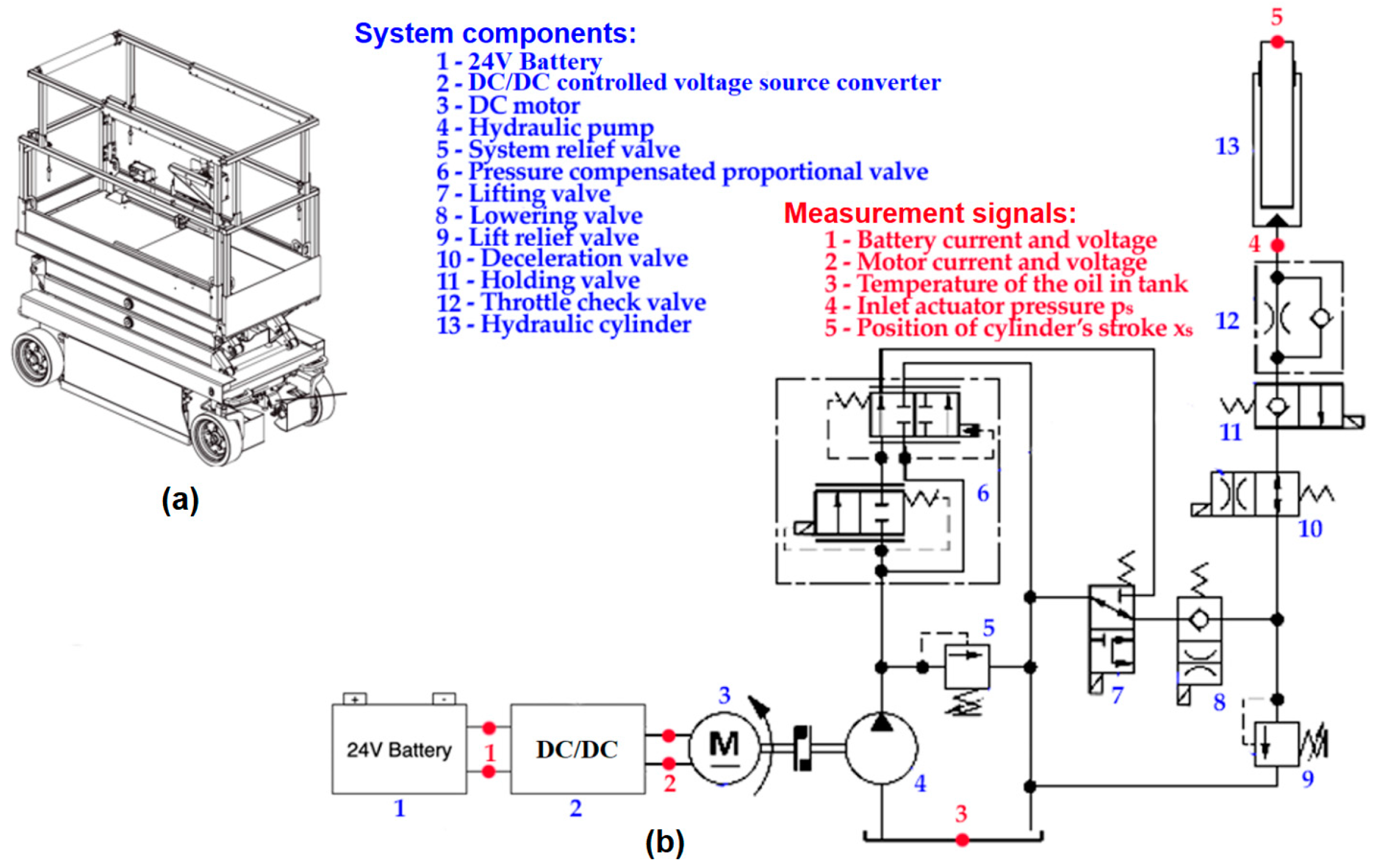
2. The Reference System—Scissor Lift

The purpose of the experimental setup is to test the conventional valve-controlled scissor lift in terms of energy consumption and to form a clear reference point. This section elaborates on the experimental approach alongside the existing hardware, and its key properties are presented. A conventional system schematic and working principles are defined in Section 2.1, while Section 2.2 presents the utilized duty cycles.

2.1. Overview of Test Arrangements

A study case system is based on a Skyjack scissor lift, where electric energy from a 24 V battery is converted into rotational mechanical energy and then into a hydraulic form. This hydraulic energy is delivered via the pump to two cylinders, which are operating the lifting platform of the scissor lift. The conventional hydraulic part of the system consists of a hydraulic cylinder (13), a pump (4), a set of valves (5–12), and an oil tank. The schematic of the conventional system is presented in Figure 1 below.
In Figure 1, the electric part of the system consists of a 24 V battery (1), a DC/DC-controlled voltage source converter (2), and a DC motor (3), that is running at constant speed. The main parameters of the utilized conventional components are represented in Table 1 below for the study case scissor lift. Red points correspond to the sensor placements for the experiment measurements.

2.2. Utilized Duty Cycles

The experimental tests were carried out with an existing conventional scissor lift to incorporate the original kinematic chains, inertia, and control interface.
The motion cycle consisted of raising the platform of the fully folded lift to its maximum height and then lowering it until the scissor lift was fully folded. 0 kg (“no load”), 96 kg, and 205 kg (1 and 2 persons, respectively) were used as payloads for the experiments. The velocity of the platform movement was recorded during all experiments. The obtained experimental data indicated similar cycles of movement with a load of 1 and 2 persons (~96 kg and ~205 kg, respectively). The recorded measurements consist of the currents and voltages of the electric motor and battery, pressure, and temperature of the oil in the system. A HIOKI power analyzer was used as a measurement facility. Duty cycles that combine various movements and payloads could not be measured due to limited access to the scissor lift. Therefore, an alternative approach to simulate such cycles and synthesize loaded measurements and unloaded measurements is used and will be described in Section 3. The limited experimental runs were performed, and the recorded data was utilized to validate simulation models for a more detailed investigation below.

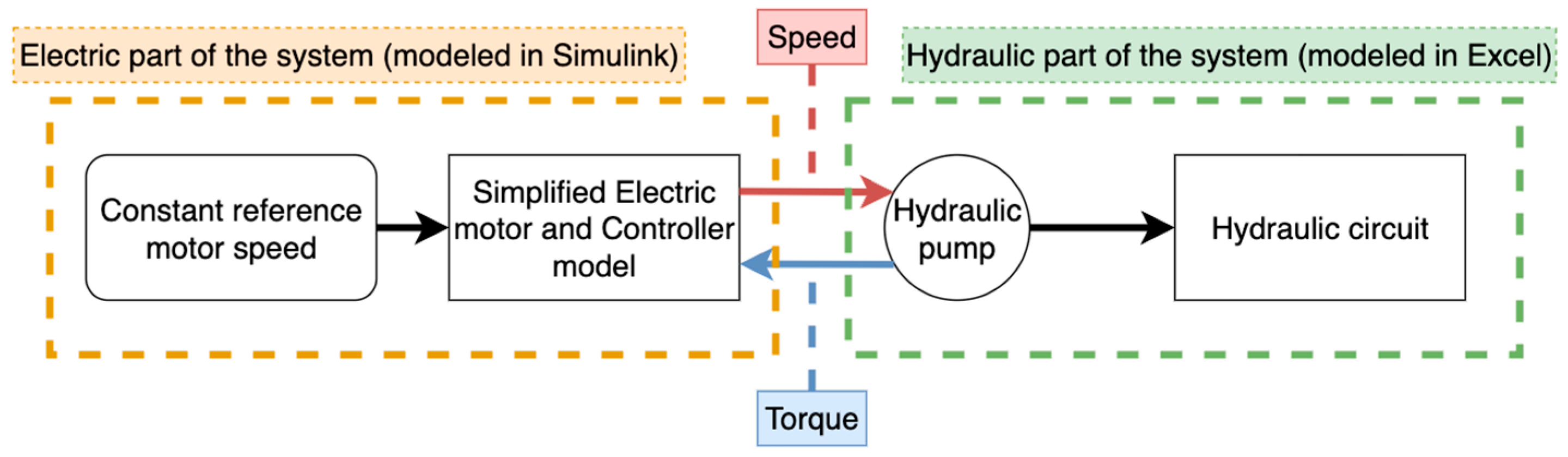
3. Model and Validation of the Reference System

The following section introduces the modeling of the components and presents the validation of the proposed models for a scissor lift as the reference system.
A direct current (DC) motor is utilized as the prime mover of a conventional scissor lift. An electric motor is utilized as a constant source of rotational power, where cylinder (platform) position control is implemented via the valve control (hydraulic part) of the conventional system realization (refer to Figure 2). The hydraulic part of the system was implemented via mathematical equations in Excel in the form of look-up tables, which were interconnected with an electric part of the system in MATLAB Simulink. The models have a data exchange via rotational speed and torque, between an electric motor and hydraulic pump.
The hydraulic system and electric drive models are described in Section 3.1 and Section 3.2, respectively, with mathematical equations and control laws. Section 3.3 illustrates the validation of the proposed models. Section 3.4 demonstrates the results of the analysis of conventional hydraulics.

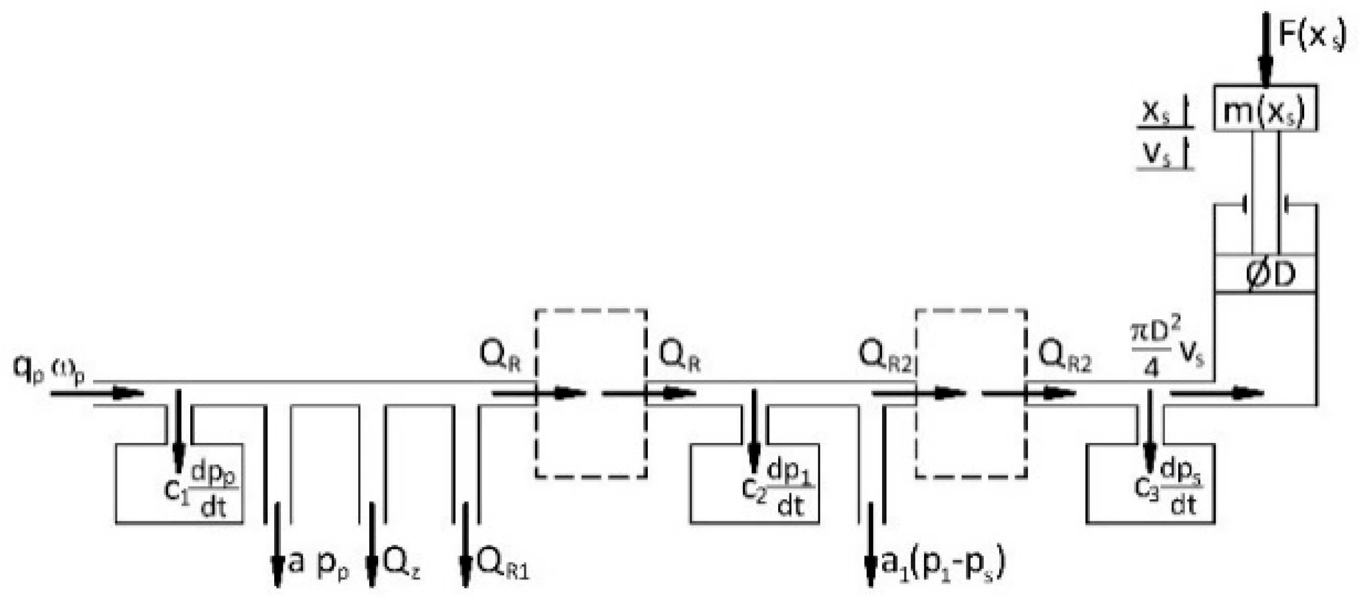
3.1. Hydraulic Components
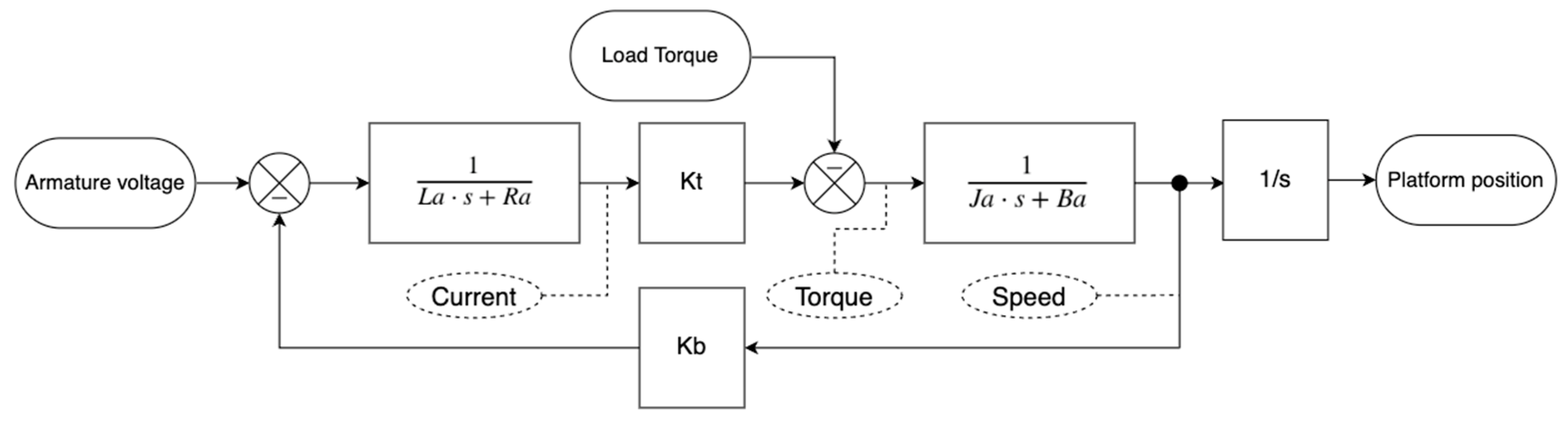
The model of the hydraulic drive is developed using a known equation of the motion of mechanical elements and the flow balance equation for the individual hydraulic lines of the hydraulic circuit [20]. Of particular note, the model valves, which were irrelevant for the drive model, were omitted. The model scheme for the lifting operation is presented in Figure 3.
The first hydraulic line connected with the hydraulic pump circuit is described by the following equation:
q p · ω p = a · p p + c 1 · d p p d t + Q R 1 + Q R + Q z ,
where qp is the pump displacement [m3/rad], ωp is the angular speed of the motor [rad/s], calculated using the mechanical characteristic of the motor, a is the leakage coefficient [m3/Ns], pp is the pressure on the pump outlet [N/m2], and c1 is the hydraulic capacity of the line [m5/N]. QR is the oil flow to an indirect branch through the flow regulator in [m3/s] and is calculated using a flow equation:
Q R = x R · A D · c D · 2 · p ρ ,
where AD [m2] is the cross-sectional area of the valve orifice, cD [-] is the coefficient of flow losses, ρ [N/m3] is the density of the hydraulic liquid, Δp [N/m2] is the pressure drop between the inlet and outlet of the valve, and xR is the signal of the valve control [-]. QR1 is the oil flow to the tank through the flow regulator in [m3/s], and Qz is the flow through a normally closed pressure relief valve in [m3/s], described by the equation:
T · d Q p z d t + Q z = h z · p p p z ,
where T is the time constant of the valve in [s], hz is the gain coefficient [m5/Ns], and pz is the valve opening pressure in [N/m2].
The second indirect hydraulic line can be described by the equation:
Q R = c 2 · d p 1 d t + Q R 2 + a 1 · p 1 p s ,
where QR2 is the oil flow through the directional valve [m3/s], c2 is the hydraulic capacity of the hydraulic line [m5/N], p1 is the pressure in the line in [N/m2], and ps is the pressure on the hydraulic actuator inlet in [N/m2].
The last hydraulic line, connected with the hydraulic actuator, is described as follows:
Q R 2 = c 3 · d p s d t + v s · π · D 2 4 ,
where c3 is the hydraulic capacitance of the third hydraulic line in [m5/N], vs is the speed of the piston rod in [m/s], and D is the diameter of the piston in [m].
The equation of the motion of the piston rod is described as follows:
m x s · d v s d t = p s · π · D 2 4 f s · v s F x s + F R ,
where xs is the movement of the piston rod [m], fs is the viscous resistance factor [Ns/m], FR is the force on the support in the lower piston position in [N], and m(xs) is the effective mass of the platform reduced to the piston rod in [kg].
The mass of the platform and efficient mass of the mechanism reduced to the platform are defined as
m x s = m p + m w + m Q · i 2 + m p p r ,
where mQ is the mass of the load [kg], mppr is the mass of the piston and piston rod in [kg], and i is the transmission ratio of the mechanical system of the scissor lift [-]. The total force acting on the actuator was calculated according to the formula:
F x s = m p + m w + m Q · g · i ,
where F(xs) is the effective load of the platform reduced to the piston in [N].
Both m(xs) and F(xs) depend on the transmission ratio i of the mechanical system, which was determined experimentally and described by the approximate equation and demonstrated in Figure 4.
In addition, the kinematic dependencies between the mechanical elements of the system are defined as
v p = v s · i ,
d x p d t = v p ,
where vp is the lifting speed of the platform and xp is the lifting height of the platform.

3.2. Electric Drive

A direct current (DC) motor is a prime mover for conventional scissor lifts. A block diagram of a DC motor is illustrated in Figure 5.
The DC motor model is formed utilizing classic differential equations which are realized in Matlab/Simulink. The time-domain equations for a DC motor are represented below. For more details, refer to [21].
U a t = R a i a t + L a d i a t d t + e b t ,
T t = K t i a t ,
e b t = K b ω t ,
J a θ ˙ ˙ t = T t B a θ ˙ t T L t ,
ω t = θ ˙ t ,
where La is the armature inductance in [H], Ra is the armature resistance in [Ohm], Kt is the torque coefficient in [Nm/A], Ja is the inertia of the motor in [kg/m2], Ba is the damping factor [Wb], and Kb is the back EMF (electromotive force) coefficient in [V/rad/s]. The DC motor transfer function is formed from the above equations by converting from the time-domain to the s-domain. For validation of the DC motor model, refer to the following section.

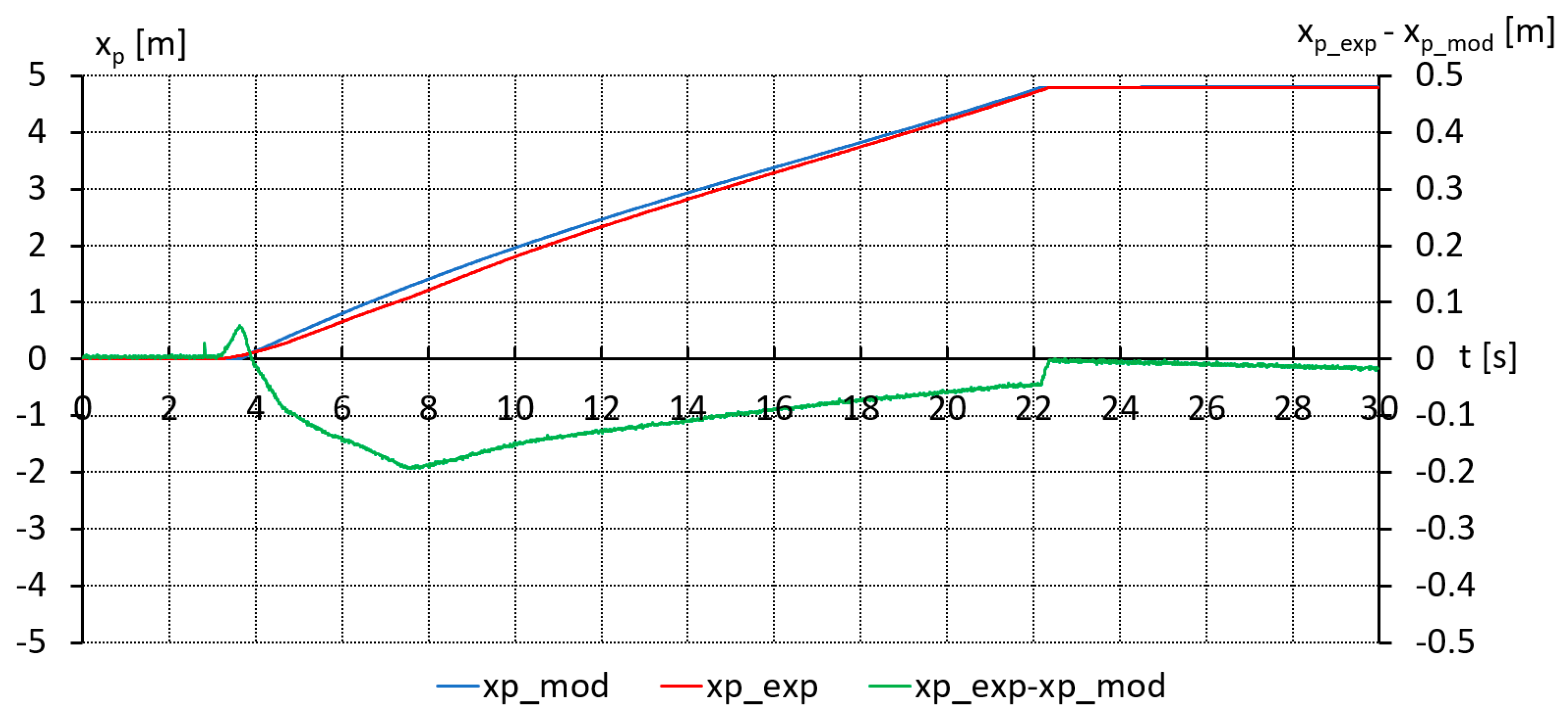
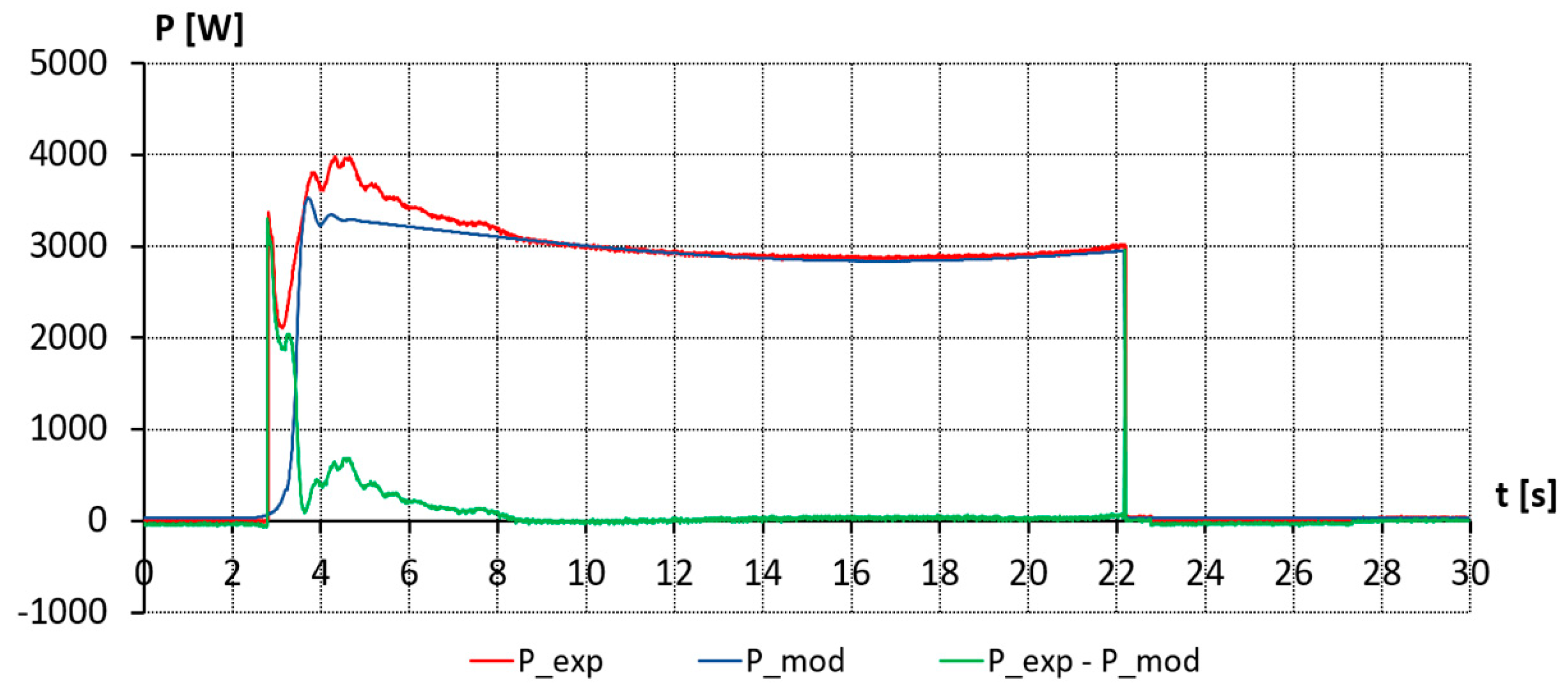
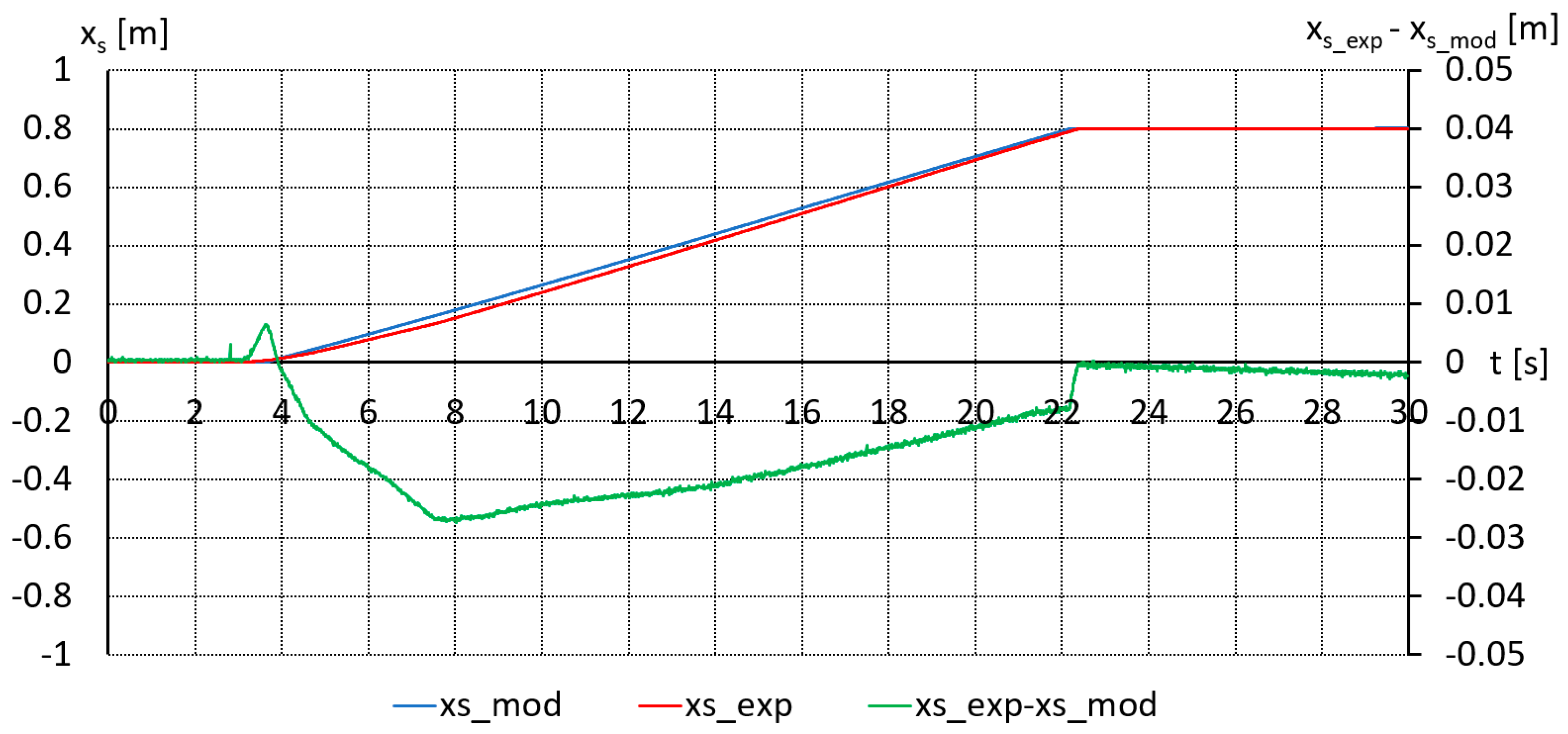
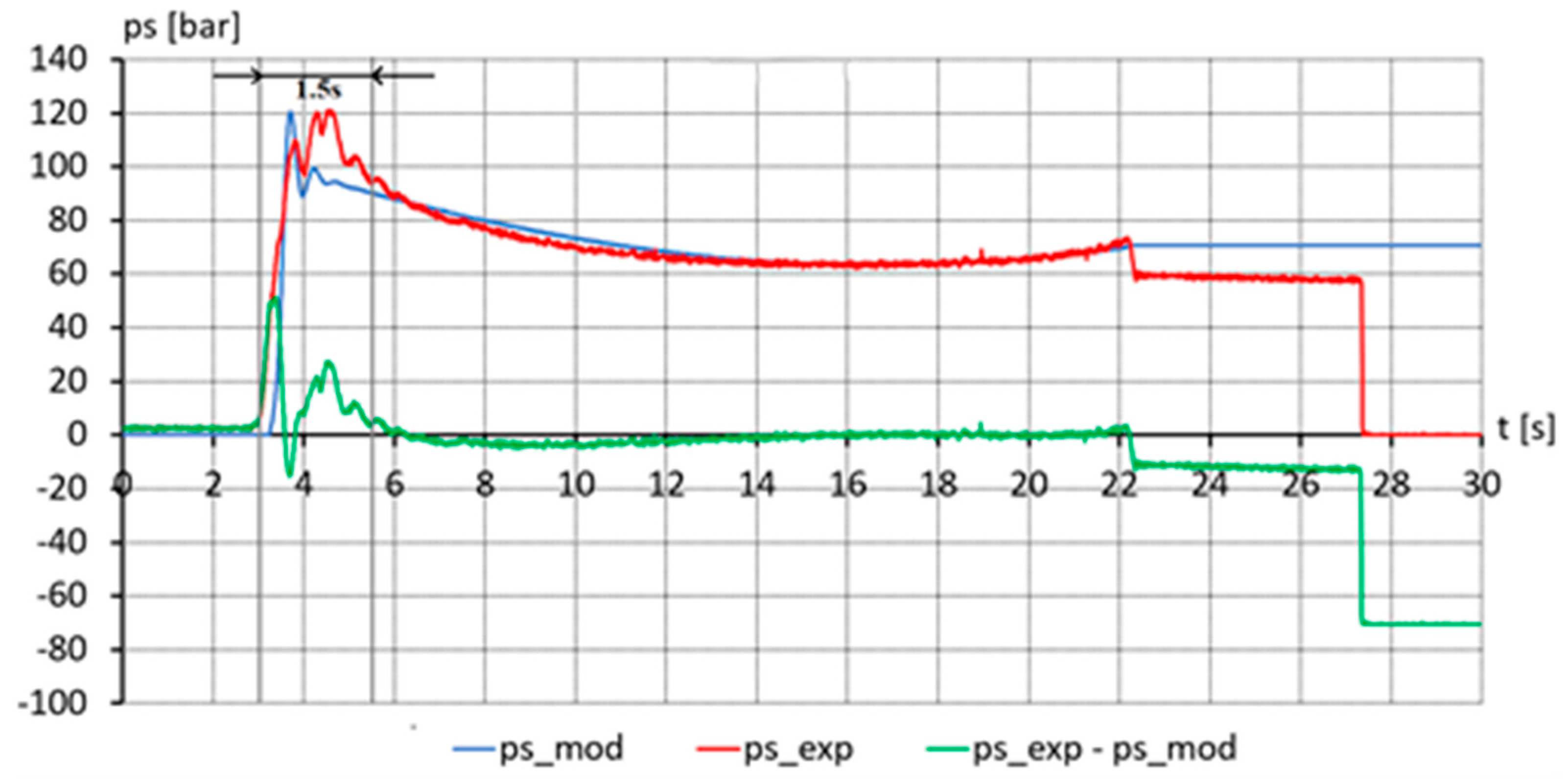
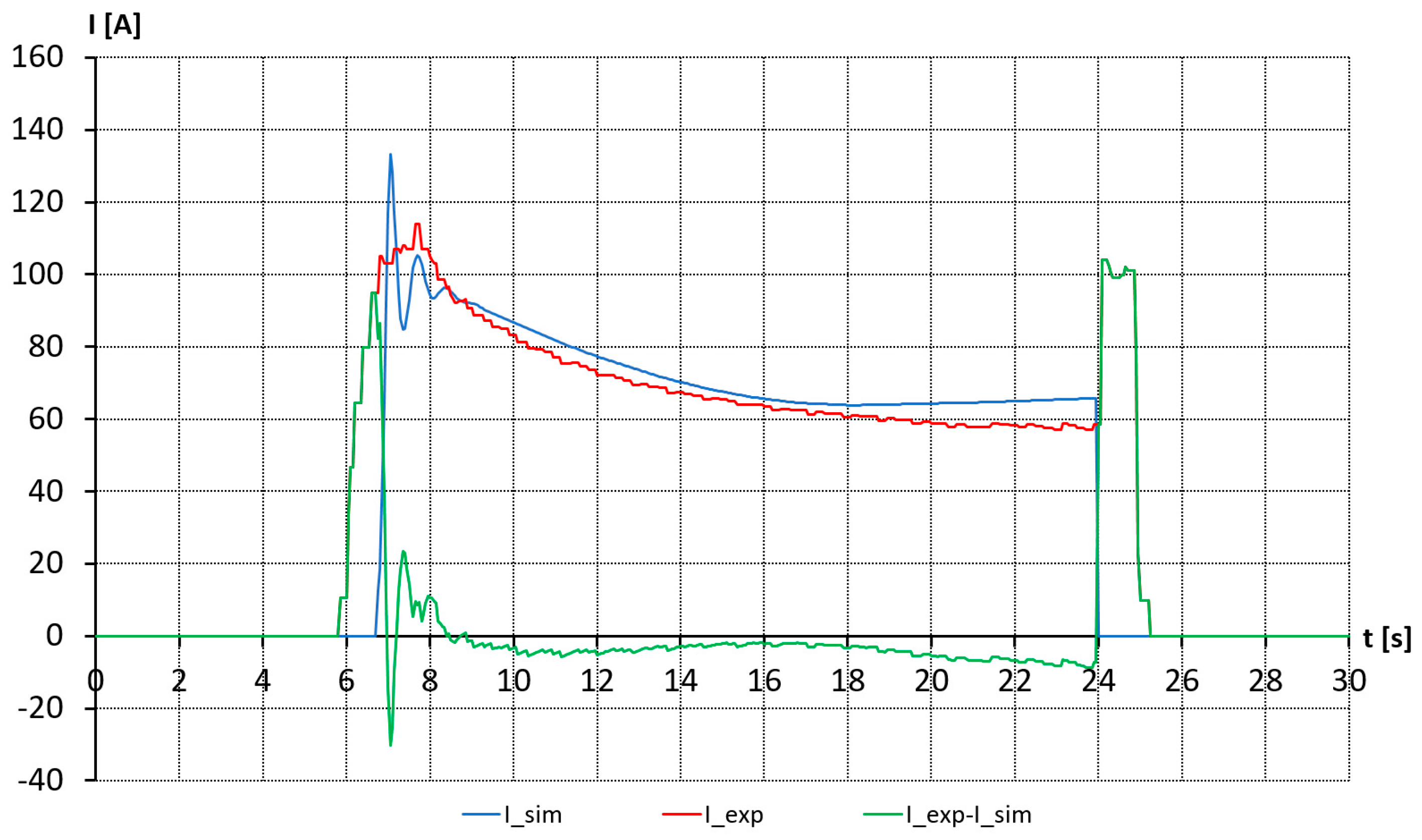
3.3. Model Validation

The model validation was conducted using the existing measured values of the following parameters of the cycle (with the subscript index exp):
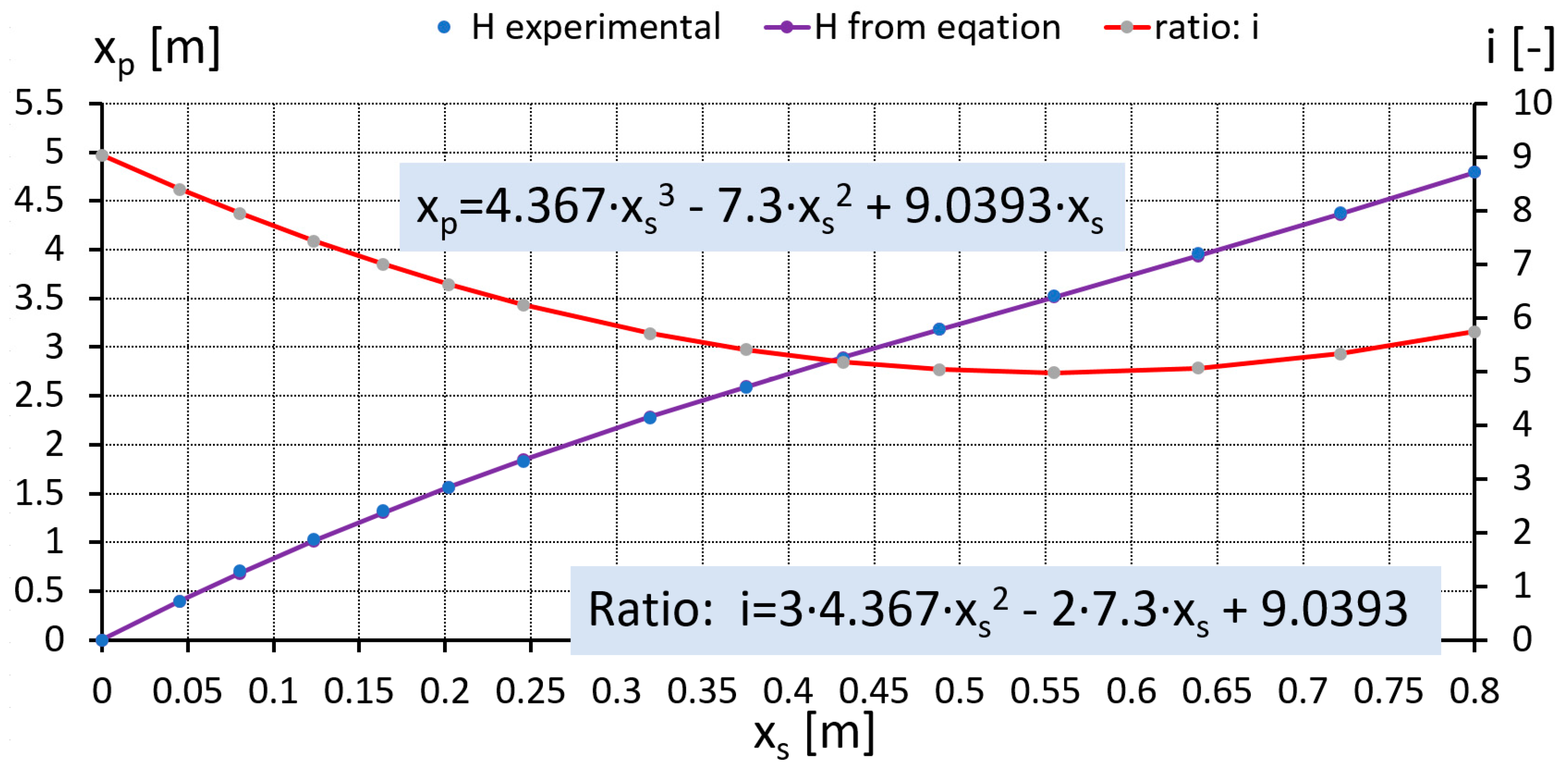
  • Displacement of piston rod xs_exp,
  • Height of the platform xp_exp,
  • Pressure ps_exp, and
  • Consumed electric motor power Pexp.
These parameters were compared with those of the simulation (with the subscript index mod). Input functions were control signals of the valves as in the experimental cycle. The validation of the model was conducted using experimental data registered on the Skyjack scissor lift loaded with 1 and 2 persons, respectively. The validation results for the hydraulic part of the scissor lift loaded with 1 person (~96 kg) during the lifting stage are illustrated in Figure 6, Figure 7 and Figure 8.
According to Figure 6 and Figure 7, both in terms of the value and the nature of changes, the proposed model reflects the behavior of the scissor lift movement. However, Figure 8 represents a pressure difference in the transient process that lasted less than 1.5 s. While stopped at the highest position of the scissor lift, the actual pressure is defined according to the operation position of the valve. These valves (6, 8, and 9 in Figure 1) were omitted in the model due to their lack of influence on the device during movement. As a result, it led to the deviation in the dynamic behavior of the system between 22.20 s and 27.18 s. After 27.18 s, the “drop to zero” is observed, where the sensors are turned off and the experiment is finished.
Figure 9 illustrates the electric motor power consumption for the scissor lift loaded with 1 person (~96 kg) during the lifting stage. The power curves reflect well the behavior of the scissor lift.
The obtained measured and simulated data, such as pressure, electric power, position of the cylinder, and platform position are used to evaluate the accuracy of the model, via the following indicator Wkavg:
W k a v g = i = 1 n k e x p k s m o d n · k e x p _ m a x · 100 % ,
where k is the value of the considered parameter or value of the variable of one sample (data point) and n is the number of samples in series (i.e., the number of samples or data points is defined by the duration time of the experiment divided by the discrete time step 0.0001 s). With respect to the indexes: exp refers to the experimental data; mod refers to the simulation data; and max refers to the maximum value of the considered parameter in the cycle.
The average values of the differences between experimental and simulation values and indicators Wkavg are presented in Table 2.
As can be seen from the performed analysis, the developed model illustrated a high compatibility with experimental values and can be used for simulation tests and analysis of the energy consumption of a conventional scissor lift.

3.4. Results of the Analysis of Conventional Hydraulics

The overall energy Eo consumed by the hydraulic system of the scissor jack consists of the energy losses to supply the valve coils Ev, the energy losses in the motor-pump system Em, the energy losses in the hydrostatic system Eh, and the effective energy Ee. The overall energy is calculated as follows:
E o = E v + E m + E h + E e ,
where the energy of the coils supply energy is defined as
E v = 0 t x R P c o i l d t ,
where xR is the signal of the valve control (in the discrete interval xR = [0, 1], respectively, for the coil power off and on) and Pcoil = 30 W is the power supply to the valve coil.
Energy losses of the motor-pump system are calculated as follows:
E m = 0 t q p p p ω p η m p d t ,
where ηmp is the efficiency of the motor-pump system.
Energy losses in the hydrostatic system Eh are defined as
E h = 0 t p p p s π · D 2 4 v s d t
and the effective energy is
E e = 0 t p s π · D 2 4 v s d t
The system efficiency is calculated as the ratio between output energy Ee to input energy Eo. Sankey diagrams were built utilizing Equations (18)–(21), and Figure 10 illustrates an example of it for a 96-kg payload during the lifting stage. The Sankey diagram is based on a validated simulation study for the scissor lift.
According to Figure 10, the efficiency of the system stands at 51.2%; hydraulics account for the majority of energy losses at 31.9%, followed by mechanical energy losses at 15.8%. The losses due to valve switching are minimal, representing only 1% of the total.
Table 3 summarizes the analysis of the Sankey diagrams and shows the consumption and their deviations according to various payloads for a single lifting cycle type that were simulated and analyzed.
According to Figure 10 and Table 3, hydraulic losses are dominating, e.g., energy losses in the motor-pump system Em and energy losses in the hydrostatic system Eh.
For all cycles, it should be noted that the single lifting cycle energy consumption is high and system efficiency is in the range of 50%. These indicate a high potential for improvement.

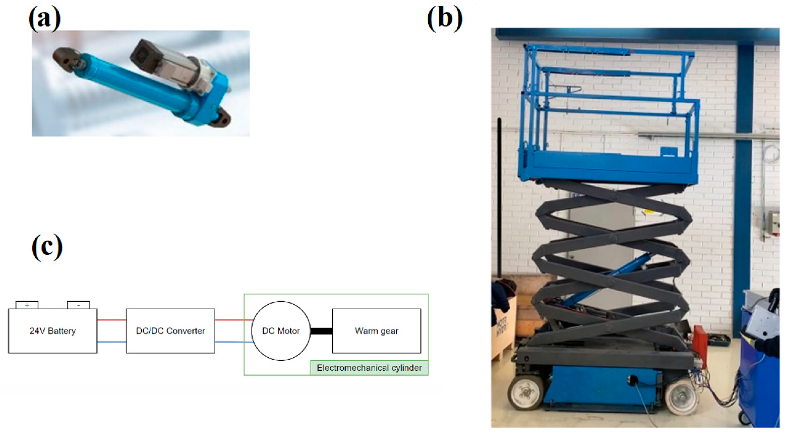
4. Proposed EMA-Based Scissor Lift

In order to illustrate the energy consumption improvement for the reference machine, an EMA-based solution was realized for the same machine. The purpose of the experimental setup is to test the electrified scissor lift with an EMA in terms of energy consumption compared to a conventional, purely valve-controlled configuration.
Section 4.1 explains the utilized hardware and its key properties as well as experimental procedure. Furthermore, this section elaborates on the selected model, simulation, and validation approach based on limited experiments.

4.1. An Overview of the Test Arrangements
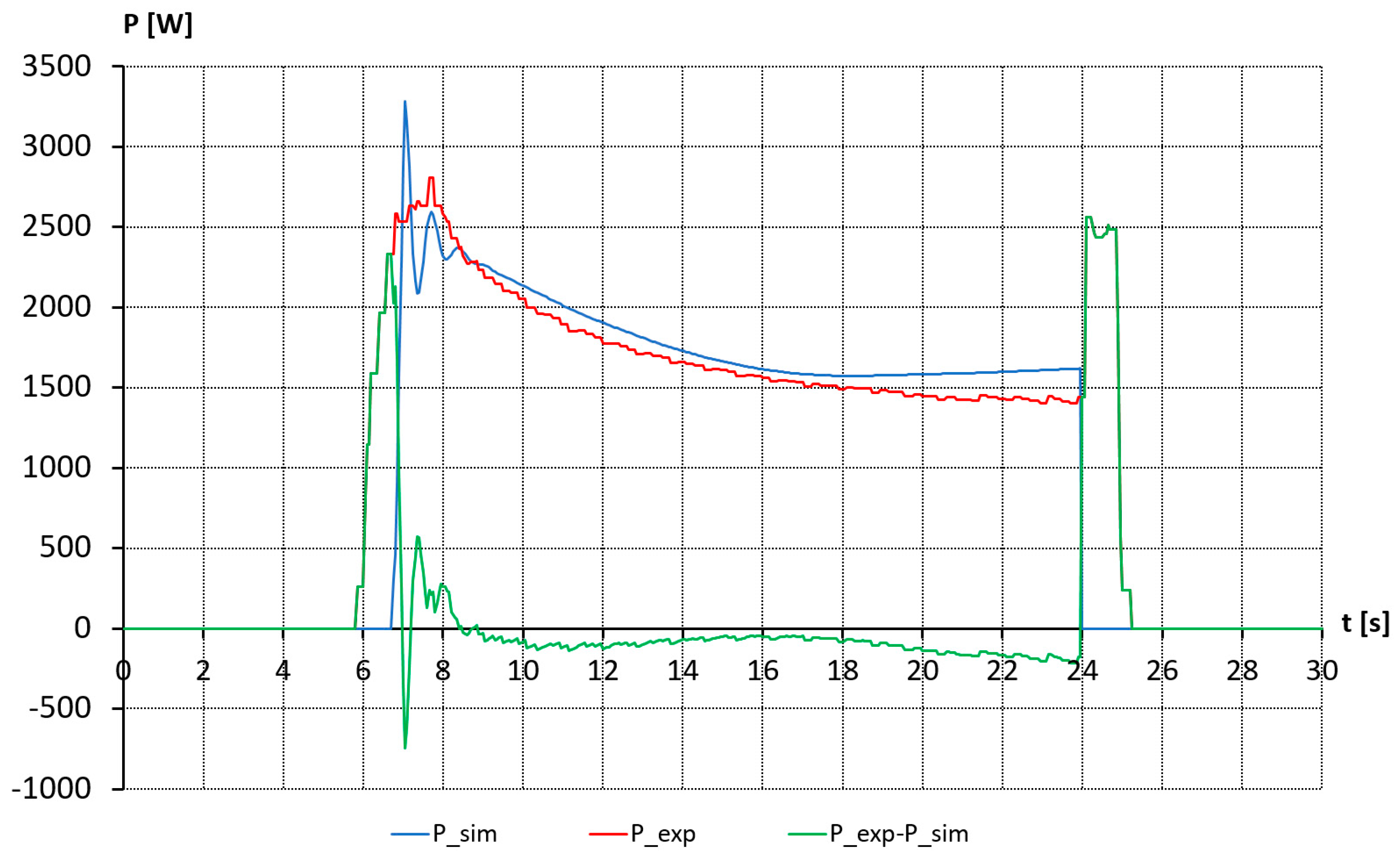
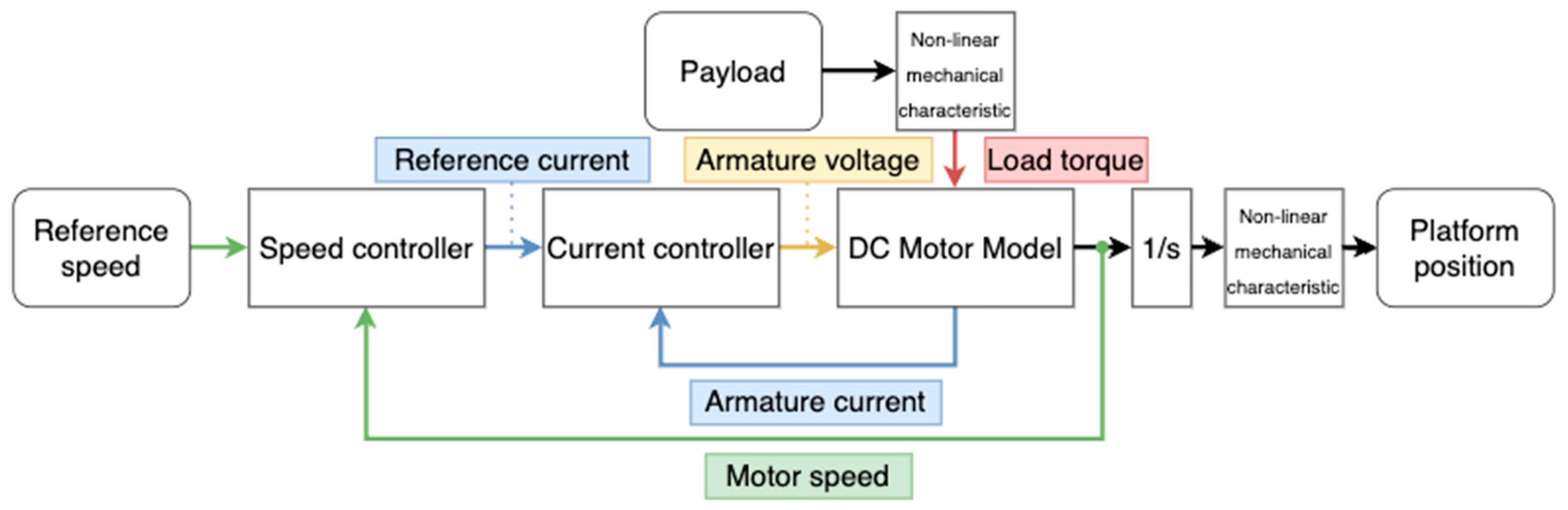
The experimental setup that contains original mechanical components and retrofitted and integrated EMA can be seen in Figure 11. The EMA system consists of a mechanical cylinder, electric DC motor, and battery (original). The photograph of the EMA-based system is presented in Figure 11b.
The main parameters of the utilized components in the EMA-based solution are represented in Table 4.
The experimental tests with EMA were carried out on the same scissor lift (after retrofitting was completed) to ensure identical operating conditions for both experimental tests. As a result, it was possible to compare energy consumption in both solutions. The obtained experimental data is based on similar lifting cycles with a load of 1 and 2 persons as for a conventional valve-controlled scissor lift. The motion cycle consisted of raising the platform of the fully folded lift to its maximum height and then lowering it until the scissor lift was fully folded. However, this research considers the lifting phase only. The velocity of the platform movement while lifting was close despite the different utilized actuators.
For all cycles, it should be noted that the maximum extension velocity of the EMA was intended to adjust to the same value-matched valve-controlled cylinder in order to achieve similar conditions for both setups. However, perfect adjustment could not be achieved with the EMA, and the difference in data can be observed, as cycles were performed manually, and a minor variation in the payload was present. Therefore, final adjustment was achieved in the simulation study.
The following subsections introduce the created EMA model and its validation.

4.2. EMA Model

In the case of the EMA-based solution, an electric DC motor is utilized with a negative feedback control system and a mechanical model of the scissor lift, which transfers the rotational power of the electric motor to the linear motion of the cabin and simulates a non-linear load. The estimated value of current and speed from the DC motor model are used as a negative feedback for suitable controllers. The block diagram of the EMA-based solution is represented in Figure 12.
The reference speed value is an input of the speed controller block which receives the negative feedback information about the actual speed of the electric motor. The output of the speed controller is a reference armature current. It is an input of the current controller, which also utilizes negative feedback information but about the actual current of the electric motor. The output of the current controller is an armature voltage.

4.3. EMA Model Validation

The results of the electric drive validation for the scissor lift loaded with 1 person are presented in Figure 13 and Figure 14. The modeled motor current and power curves reflect well the experimental data obtained from the scissor lift experimental setup.
However, in Figure 13 and Figure 14 from 24 s to 25.1 s, experimental and simulated data are differentiated from each other. This can be explained by the braking of the electric motor in the experimental conditions after activation of the locking mechanism. A simplified simulation model was utilized in this study, and no braking current was observed.

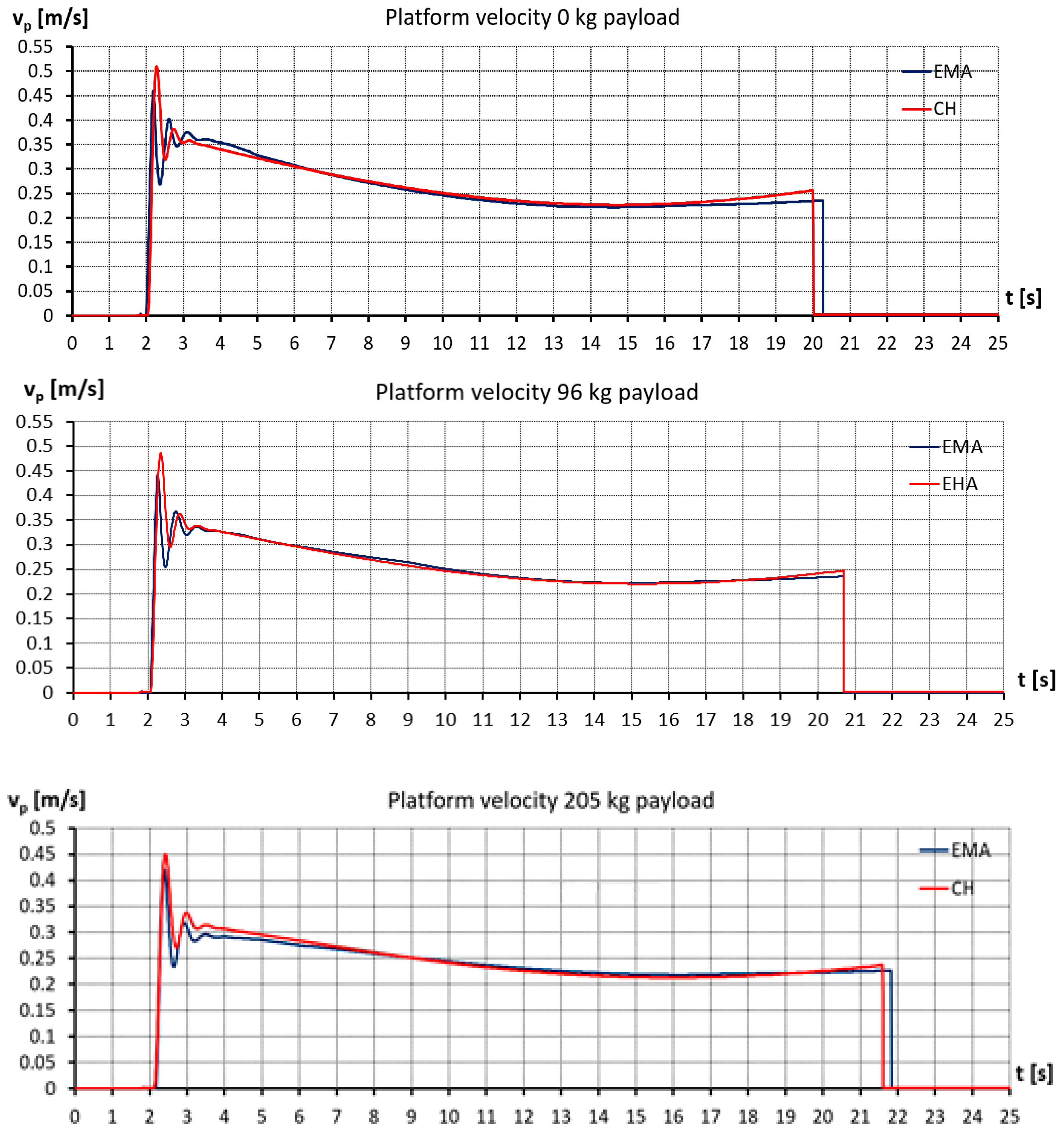
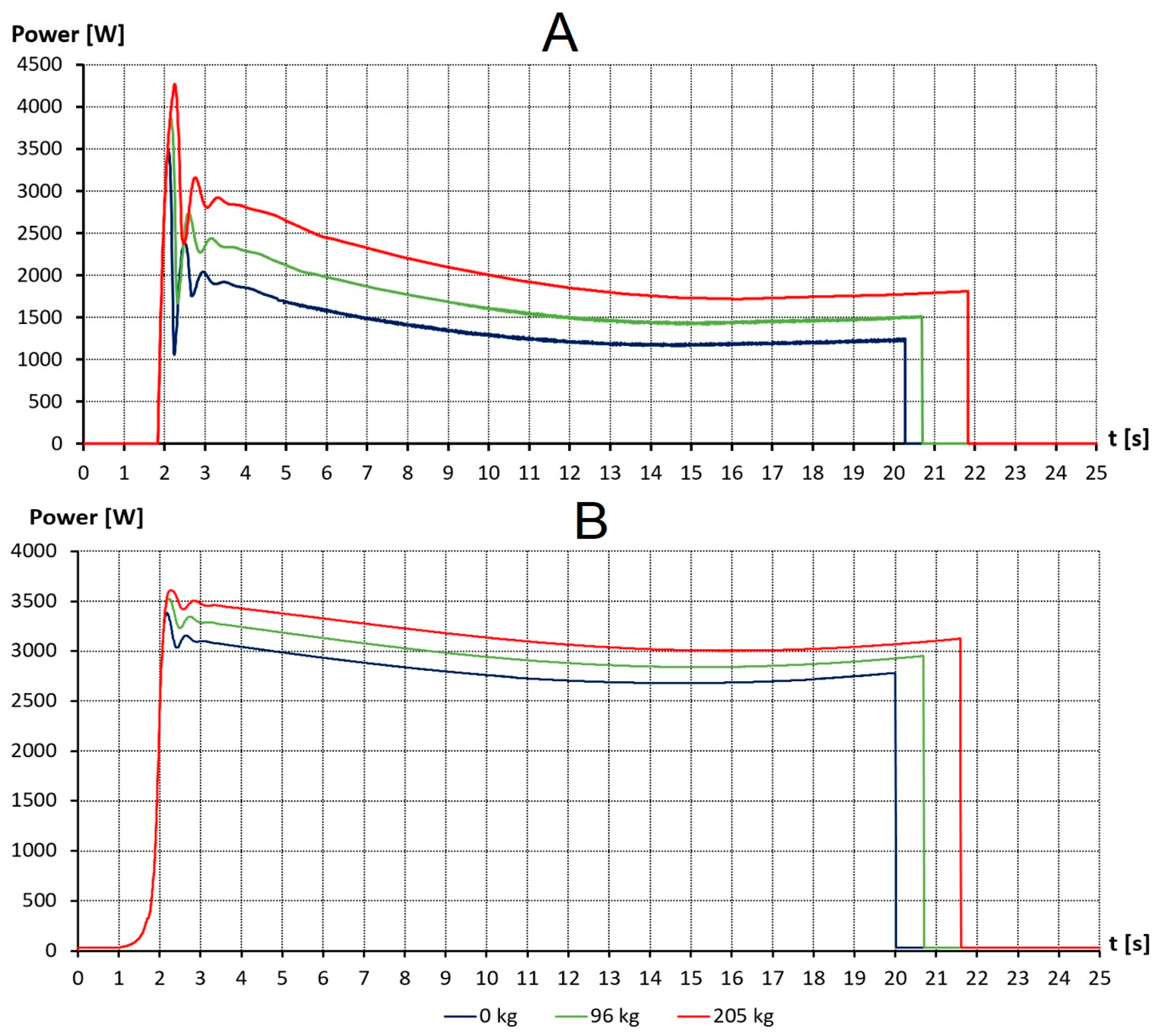
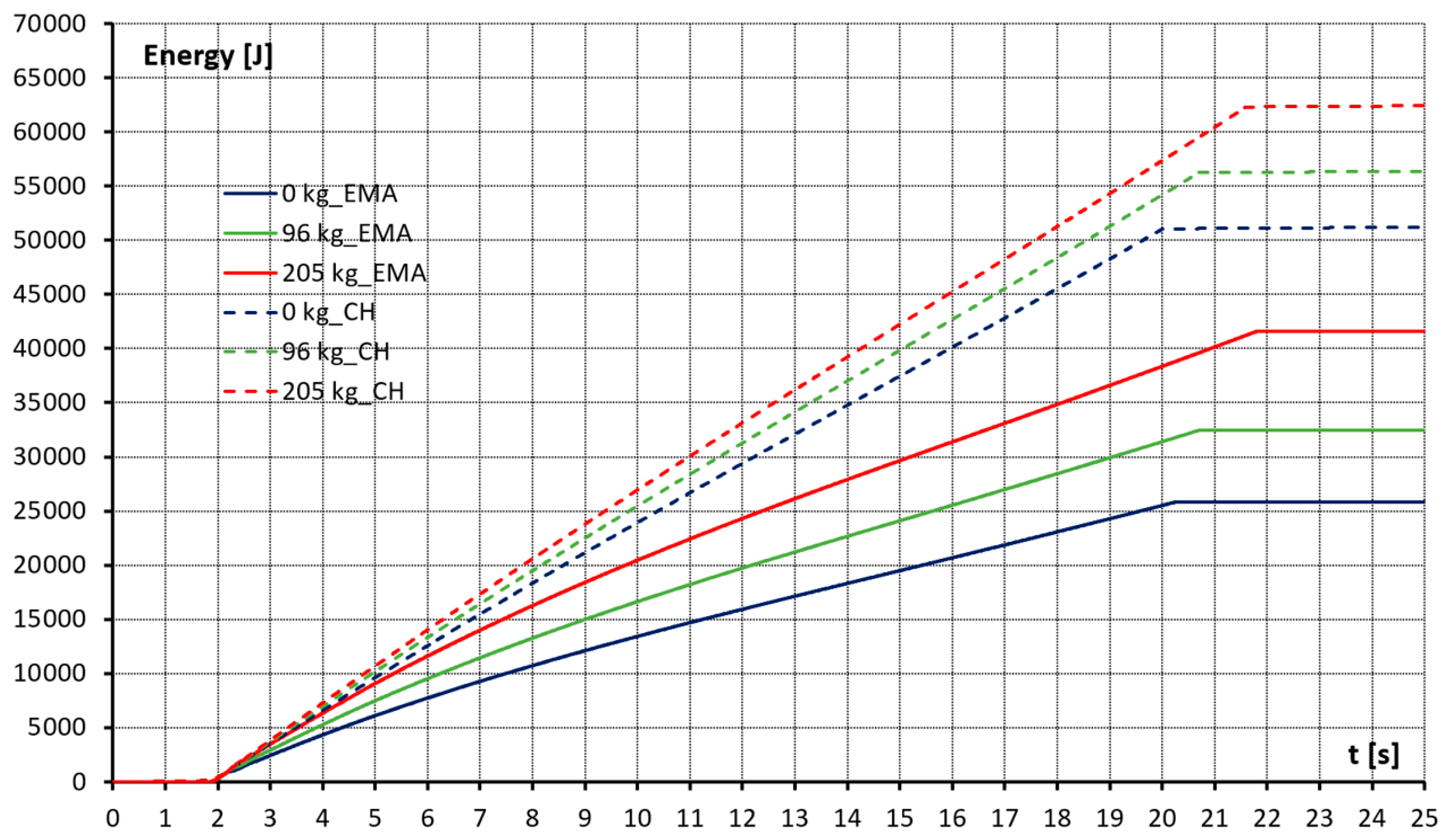
5. Analysis and Discussion

This section contains an analysis and comparison of an EMA-based solution (indicated as EMA) and a conventional hydraulic (purely valve-controlled, indicated as CH) configuration of the scissor lift system. As mentioned before, the comparison is based on validated simulation models due to the limited experimental data which were available for this study.

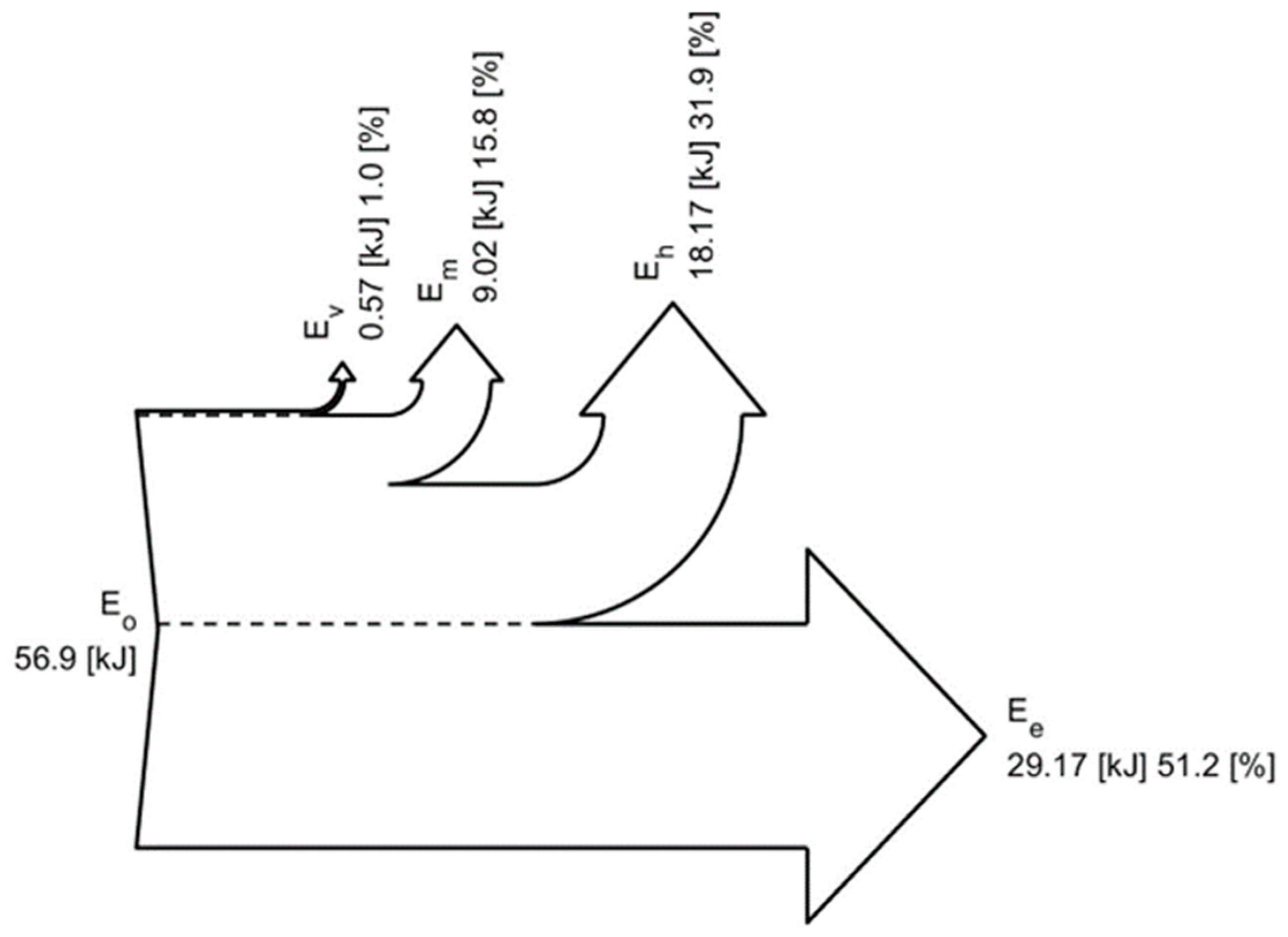
5.1. Power and Energy Consumption Analysis

Figure 15 shows the cycle comparison of the velocity of the scissor lift platform vp for the CH- and EMA-based solutions with 0 kg, 96 kg, and 205 kg payloads for the lifting operation. As can be seen in the figure, there is an acceptable result between height and velocity values, and the simulation results can be utilized for further analysis.
Figure 16 illustrates the power comparison with different payloads for the CH- and EMA-based solutions for the lifting cycle. A significant drop in the power requirement can be observed; the larger payload saw a reduction from 3.5 to 3 kW, while the zero-payload case experienced a reduction from 3 to less than 2 kW.
Figure 17 compares the energy consumption with the two solutions for various payloads. The energy consumed by a single lifting cycle with the CH is 63 kJ for maximum payload, while the same cycle and payload with the EMA-based solution consumed only 41 kJ. This delivers an energy savings of 35%. The significant 50% saving was demonstrated with a zero payload, where energy consumption dropped from 51 to 25 kJ.
In addition, the work duration of both systems was compared by calculating the number of work cycles for one complete battery charge cycle, as demonstrated in Table 5. In this simplified calculation, the following assumptions were made. The standard energy source of the conventional hydraulics-based machine is 4 × 6 V (24 V overall), 225 Ah battery. As a result, a fully charged battery is able to accumulate 5.4 kWh of energy (see Table 5 below). The comparative analysis does not take into account the charging losses and aging of the battery. It can be characterized as an ideal case scenario. Based on Table 5, the EMA-based solution can perform a larger number of cycles, increasing by 248 for 96 kg and by 151 for 205 kg payloads.

5.2. Techno-Economic Analysis

The last subsection shows that the energy efficiency of the investigated scissor lift can be significantly improved by applying EMA in an ideal case. However, in order to represent a commercially relevant solution, cost efficiency is also required. Therefore, the required energy consumption for the two setups that were simulated are compared to the expected energy cost over the one-year operation of the scissor lift. This is intended to see if the EMA-based concepts can outperform the conventional purely valve-controlled concept also in terms of energy savings and electricity costs.
Since the cost of electricity varies significantly, depending on the operation conditions and countries, two different scenarios are considered. For Scenarios 1 and 2, the electricity values are chosen to represent Poland and Finland, respectively. For the energy consumption and operation condition, different assumptions are made as well for the two scenarios.
In Scenario 1, the two scissor lifts are considered to work 200 days per year with a typical one-shift full-time operation with 100 cycles per day. Furthermore, it is assumed that the work cycle consists of a lifting and lowering cycle. For the electricity costs, the Polish prices in September 2022 are taken as a reference. The price for households, excluding value-added tax (VAT) and other recoverable taxes and levies, is used: 0.177 EUR/kWh [24].
For Scenario 2, the chosen cycle is the same as Scenario 1 but with Finnish prices of 0.418 EUR/kWh [24].
Thus, taking into account the average efficiency of the charger which stands at 85%, approximate economic calculations were obtained and are presented in Table 6.
The summary of Table 6 demonstrates that a significant economical savings can be obtained with an EMA-based solution. The EMA-based system consumed less energy than CH-based system and saves from 32% to 41% after 200 working days according to the ideal case scenario and simplified calculations. Consequently, this will positively impact the payback time of these EMA-based systems.

6. Discussion and Future Outlook

The purpose of this case study was to investigate the effect of the EMA-based solutions on the energy consumption for the scissor lift study case. The simulation models were built in this investigation in order to overcome the limitation of the existing experimental data. The hydraulic component models were built based on classic volume theory, which takes into account the pressure differences across the components but also the compressibility of the oil. However, thermal losses were not considered in this research. In this paper, the losses of the electric motor DC drive were calculated, and the controller was tuned to meet the set dynamic requirements demanded by the rotational speed and torque demonstrated during experimental tests. Furthermore, the created models were partially validated with measurements performed with a scissor lift.
The final simulations of the scissor lift equipped with the CH- and EMA-based solutions managed with simple PID controllers to achieve similar single lifting cycles (see Figure 16). The typical lifting velocity of the platform with a varying payload from 0 kg to 205 kg was utilized, where the maximum payload is 250 kg (according to the scissor lift manufacturer).
In Figure 17, the results demonstrate that the proposed EMA-based solution yields lower energy consumption results compared to the conventional hydraulic solution. The efficiency of the scissor lift was improved, and energy consumption was reduced by 35–50% for the lifting cycle by switching from the conventional to the proposed EMA-based solution. In conclusion, the significant reduction in energy consumption leads to an extension in the working time of the scissor lift with the existing battery capacity.
After conducting a techno-economic analysis, it was determined that utilizing an electrified scissor lift instead of a conventional one yields a notable advantage. Considering the typical lifespan of these machines, which is commonly accepted as 30 years, the total operating cost savings over the entire lifespan amount to over 50% of the cost of machine.
The drawback of the proposed system is that the overall costs would increase, since each EMA requires one variable speed drive with servo motor. In addition, the EMA would be under mechanical loads during each working cycle of the system and thus increase mechanical stress and may cause premature failure.
However, the advantages stated in the Section 1 outweigh these drawbacks for many applications. Further steps will investigate the lowering phase of the cycle and concentrate on the possibilities of recuperation energy and extending the working time of the scissor lift powered by the battery.
The findings of the study demonstrate the importance of the research, and therefore, it is highly justifiable to proceed with its continuation. This paper exclusively examined the comparison between CH- and EMA-based systems during the lifting cycle; however, the lowering cycle was excluded. Future research work will focus on investigating energy consumption and recovery and analyzing the duration of the lowering cycle. Moreover, these future plans encompass an evaluation of the complete operational cycle of the installation, which includes a single battery charge, in order to provide a comprehensive understanding of its performance.

7. Conclusions

The presented work concentrated on analyzing the impact and improvements in a scissor lift with the utilization of EMA-based solutions for the lifting functions of the machine during a single cycle. Models of conventional hydraulics and EMA were created and validated with experimental data for 1- and 2-person lifting cycles. The performed validation of the model demonstrated a high compatibility with real values and was utilized for a simulation investigation. The simulation study was performed with 0-, 1-person, and maximum payloads for the studied scissor lift. Power and energy consumption of non-efficient conventional hydraulic (CH-) and EMA-based systems were determined for the single lifting cycle and can achieve improvements in energy consumption by 35–50%.
The research results demonstrated that the proposed EMA-based configuration brings benefits from an energy point of view. The power requirements of the scissor lift can be improved up to 50% by switching to EMA. However, the question of reliability and initial cost were not investigated and need to be tackled in future research steps.

Author Contributions

Conceptualization, T.M.; methodology, T.M. and Ł.S.; software, V.Z., Ł.S. and A.K.; validation, Ł.S., A.K. and V.Z.; formal analysis, T.M., Ł.S., V.Z. and A.K.; investigation, T.M., Ł.S., V.Z. and A.K.; resources, T.M. and Ł.S.; data curation, T.M., Ł.S., V.Z. and A.K.; writing—original draft preparation, T.M., Ł.S., V.Z. and A.K.; writing—review and editing, T.M. and V.Z.; visualization, Ł.S., V.Z. and A.K.; supervision, T.M. and Ł.S.; project administration, T.M.; funding acquisition, T.M. All authors have read and agreed to the published version of the manuscript.

Funding

The research was enabled by the financial support of Tampere University, Automation Technology and Mechanical Engineering Department, IHA-Innovative Hydraulics, and Automation Laboratory and support of the EMMA2 project 4674/31/2021 (Business Finland).

Data Availability Statement

Data available in a publicly accessible repository.

Conflicts of Interest

The authors declare no conflict of interest.

References

  1. Viaggi, R. Annual Economic Report; CECE: Brussels, Belgium, 2021; Available online: https://www.cece.eu/stream/cece-annual-economic-report-2021 (accessed on 14 May 2023).
  2. Emission Standards: Europe: Nonroad Engines. dieselnet.com. Available online: https://dieselnet.com/standards/eu/nonroad.php (accessed on 14 May 2023).
  3. Fassbender, D.; Zakharov, V.; Minav, T. Utilization of Electric Prime Movers in Hydraulic Heavy-Duty-Mobile-Machine Implement Systems. Autom. Constr. 2021, 132, 103964. [Google Scholar] [CrossRef]
  4. Abuowda, K.; Okhotnikov, I.; Noroozi, S.; Godfrey, P.; Dupac, M. A Review of Electrohydraulic Independent Metering Technology. ISA Trans. 2020, 98, 364–381. [Google Scholar] [CrossRef] [PubMed]
  5. Donkov, V.H.; Andersen, T.; Linjama, M.; Ebbesen, M. Digital Hydraulic Technology for Linear Actuation: A State of the Art Review. Int. J. Fluid Power 2020, 21, 263–304. [Google Scholar] [CrossRef]
  6. Digital Displacement® Pumps. Available online: https://www.danfoss.com/en/products/dps/pumps/digital-displacement-pumps/digital-displacement-single-and-multiple-outlet-pumps/ (accessed on 14 May 2023).
  7. INNAS—Fluid Power Innovation. Available online: https://www.innas.com/index.html (accessed on 14 May 2023).
  8. Axial Piston Pumps AX. Bucher Hydraulics. Available online: https://www.bucherhydraulics.com/en/products/pumps-and-motors/pumps/axial-piston-pumps-ax (accessed on 14 May 2023).
  9. NorrDigi—Energy Saving Motion Control. Available online: https://www.norrhydro.com/en/norrdigi-digital-hydraulic-solution (accessed on 14 May 2023).
  10. Minav, T.A.; Heikkinen, J.E.; Pietola, M. Electric-Driven Zonal Hydraulics in Non-Road Mobile Machinery. In New Applications of Electric Drives; Intechopen: Rijeka, Croatia, 2015. [Google Scholar] [CrossRef]
  11. Koitto, T.; Kauranne, H.; Calonius, O.; Minav, T.; Pietola, M. Experimental Study on Fast and Energy-Efficient Direct Driven Hydraulic Actuator Unit. Energies 2019, 12, 1538. [Google Scholar] [CrossRef]
  12. Qu, S.; Fassbender, D.; Vacca, A.; Busquets, E. A High-Efficient Solution for Electro-Hydraulic Actuators With Energy Regeneration Capability. Energy 2021, 216, 119291. [Google Scholar] [CrossRef]
  13. Qiao, G.; Liu, G.; Shi, Z.; Wang, Y.; Ma, S.; Lim, T.C. A Review of Electromechanical Actuators for More/All Electric Aircraft Systems. Proc. Inst. Mech. Eng. Part C J. Mech. Eng. Sci. 2017, 232, 4128–4151. [Google Scholar] [CrossRef]
  14. Hagen, D.; Padovani, D.; Choux, M. Guidelines to Select Between Self-Contained Electro-Hydraulic and Electro-Mechanical Cylinders. In Proceedings of the 2020 15th IEEE Conference on Industrial Electronics and Applications (ICIEA), Kristiansand, Norway, 9–13 November 2020. [Google Scholar] [CrossRef]
  15. EX02—Prototype Electric Excavator. Available online: https://www.volvoce.com/global/en/this-is-volvo-ce/what-we-believe-in/innovation/prototype-electric-excavator/ (accessed on 14 May 2023).
  16. eFuzion: Innovative Technology for a Sustainable Future. YANMAR. Available online: https://www.yanmar.com/global/about/ymedia/article/efuzion.html (accessed on 14 May 2023).
  17. DaVinci AE1932 All-Electric Scissor Lift. Available online: https://www.jlg.com/en/equipment/scissor-lifts/electric/davinci-series-scissor-lifts/ae1932 (accessed on 14 May 2023).
  18. New All-Electric Bobcat Compact Track Loader Breaks Fresh Ground. Industrial Vehicle Technology International. Available online: https://www.ivtinternational.com/news/hybrid-electric-vehicles/new-all-electric-bobcat-compact-track-loader-breaks-fresh-ground.html (accessed on 14 May 2023).
  19. Inc, Moog Construction Article: Komatsu’s All Electric Wheel Loader Prototype in Partnership with Moog at Bauma 2022. Available online: https://www.moogconstruction.com/News/komatsu-s-all-electric-wheel-loader-prototype-in-partnership-wit.html (accessed on 14 May 2023).
  20. VÖGELE. Bauma 2022|New Mini Road Pavers from VÖGELE. Available online: https://www.wirtgen-group.com/en-fi/news/voegele/mini-500e-and-mini-502e/ (accessed on 14 May 2023).
  21. Bao, Z. Study on Simulation of System Dynamic Characteristics of Hydraulic Scissor Lift Based on Load-Sensing Control Technology. IOP Conf. Ser. Mater. Sci. Eng. 2019, 612, 042036. [Google Scholar] [CrossRef]
  22. Stawiński, Ł.; Kosucki, A.; Morawiec, A.; Sikora, M. A New Approach for Control the Velocity of the Hydrostatic System for Scissor Lift with Fixed Displacement Pump. Arch. Civ. Mech. Eng. 2019, 19, 1104–1115. [Google Scholar] [CrossRef]
  23. Motiomax by Norrhydro. Available online: https://www.norrhydro.com/en/motiomax (accessed on 14 May 2023).
  24. Electricity Prices. Global Petrol Prices. Available online: https://www.globalpetrolprices.com (accessed on 14 May 2023).
Figure 1. (a) Conventional scissor lift; (b) schematics of the lifting conventional hydraulics.
Actuators 12 00394 g001
Figure 2. Block diagram of the system for a conventional scissor lift.
Actuators 12 00394 g002
Figure 3. The scheme of the hydraulic drive model during lifting.
Actuators 12 00394 g003
Figure 4. Transmission ratio i of the mechanism and lifting height of the platform xp as a function of the piston rod displacement xs.
Actuators 12 00394 g004
Figure 5. Block diagram of the DC motor model.
Actuators 12 00394 g005
Figure 6. The piston rod displacement xs with a payload of 96 kg (1 person).
Actuators 12 00394 g006
Figure 7. The height of the platform xp with a payload of 1 person.
Actuators 12 00394 g007
Figure 8. The pressure ps with a payload of 1 person.
Actuators 12 00394 g008
Figure 9. The consumed electric motor power P with a payload of 1 person.
Actuators 12 00394 g009
Figure 10. The Sankey diagram for a conventional scissor lift with a payload of 96 kg during a single lifting cycle.
Actuators 12 00394 g010
Figure 11. (a) Utilized EMA actuator, adopted from [23], (b) EMA-based solution for a scissor lift, and (c) Schematic of EMA-based system.
Actuators 12 00394 g011
Figure 12. Block diagram of the DC motor for the EMA-based scissor lift.
Actuators 12 00394 g012
Figure 13. The motor current with a payload of 1 person.
Actuators 12 00394 g013
Figure 14. The consumed electrical motor power with a payload of 1 person.
Actuators 12 00394 g014
Figure 15. The velocity of a platform vp with 0 kg, 96 kg, and 205 kg payloads.
Actuators 12 00394 g015
Figure 16. The consumed (system) power P from the battery for the EMA-based (A) and CH-based (B) solutions for the single lifting cycle.
Actuators 12 00394 g016
Figure 17. Comparison of the energy consumption for the CH- and EMA-based solutions for the single lifting cycle.
Actuators 12 00394 g017
Table 1. Utilized components and their main parameters for a conventional scissor lift.
ComponentMain Parameters
Pumpqp = 3.8 cc/rev; pn = 210 bar
CylinderD = 80 mm; stroke length = 800 mm
DC motorVoltage: 24 V; Pn = 3 kW; nn = 4500 rpm
Table 2. Validation of the model.
96 kg205 kg
ParameterAverage Difference between Simulation and ExperimentalWavg [%]Average Difference between Simulation and ExperimentalWavg [%]
xs [m]0.01151.440.00831.04
ps [bar]10.826.015.322.96
xp [m]0.071.46no exp. data
Pel [W]113.242.83182.454.56
Table 3. Energy consumption of the conventional hydraulics–based scissor lift.
Parameter0 kg96 kg205 kg
Eo [kJ]52.256.963
Ev [kJ]0.560.570.60
Em [kJ]8.259.029.98
Eh [kJ]18.0318.1718.40
Ee [kJ]25.3429.1734.01
η [%]48.651.254
Table 4. Utilized components and their main parameters for an EMA-based scissor lift.
ComponentMain Parameters
Mechanical cylinderStroke 800 mm
Lead 0.64 mm/rev
DC motorVoltage: 24 V; Pn = 4 kW; nn = 3000 rpm
Table 5. Comparison of work duration between conventional hydraulics- and electromechanical actuator-based systems with a fully charged battery in an ideal case scenario.
Payload, kgConv. Sys. Number of CyclesEMA. Sys. Number of Cycles
96344592
205311462
Table 6. Comparison of expenses between conventional hydraulics and electromechanical actuator-based systems for 200 days per year.
CountryElectricity Price, C/kWh Payload, kgConv. Sys. Expenses, EUREMA. Sys. Expenses, EUREconomy, %
Poland0.17796146.6785.1541.95
205162.25109.0332.81
Finland0.41896346.38201.0941.95
205383.17257.4932.81
Disclaimer/Publisher’s Note: The statements, opinions and data contained in all publications are solely those of the individual author(s) and contributor(s) and not of MDPI and/or the editor(s). MDPI and/or the editor(s) disclaim responsibility for any injury to people or property resulting from any ideas, methods, instructions or products referred to in the content.

