Abstract
Hydraulic cylinders are well known as cheap and robust actuators for moving heavy loads, especially in harsh environments. For this reason, they are often used in construction machines such as excavators. Basically, the hydraulic cylinders are controlled by four-way proportional spool valves, resulting in poor energy efficiency due to resistance control. Furthermore, because all valve edges are located at the same spool, common proportional valves suffer from limited flexibility with regard to different loads. Independent metering (IM) is a well-known strategy for making proportional hydraulic drives more efficient and more flexible because each port of the actuator can be connected individually to pressure or tank by independent two-way proportional valves. In this paper, the IM concept is realized as an open-loop control for a hydraulic cylinder drive, which, in combination with a human operator, constitutes a so-called cybernetic proportional system (CPS). The piston velocity commanded by the operator is controlled by the compensation of the static characteristics of the proportional seat-type valves. Basic simulations show the benefits and also the problems of open-loop independent metering. Furthermore, measurements on one actuator of a real excavator regarding controllability and energy consumption are presented.
1. Introduction
Hydraulic drive technology is often the best choice for linear actuation in harsh environments, such as, for instance, in construction machinery. In such applications, the hydraulic actuators are realized as cheap and robust differential cylinders. The control of such cylinders is still mostly realized by four-way proportional valves, where all valve edges are located at the same spool (see for instance [1]). In fact, this control strategy with one degree of freedom is very simple but suffers mainly from poor energy efficiency due to resistance control. Of course, in most off-road construction machines such as the aforementioned excavators, different kinds of load sensing systems lower the energy consumption and thus the fuel consumption in order to fulfill ecological and economical requirements. However, the coupling of all control edges in common four-way proportional valves results in a restriction of flexibility, which impedes the further optimization of the control and, in turn, the energy consumption of the drive. For this reason, the hydraulic scientific community has explored the field of independent metering (IM) for more than two decades; this encompasses the situation where each of the four valve edges () is realized by a separate and, thus, individually controlled two-way proportional valve, such as was proposed in the patents [2,3]. A fundamental and comprehensive scientific contribution to IM is provided by the thesis [4], where the concept of IM in a four-valve assembly was investigated regarding control modes and energy consumption. Basically, the additional degrees of freedom lead to five metering modes: power extension, power retraction, high-side regenerative extension, low-side regenerative extension, and low-side regenerative retraction. According to the load situation, a convenient transient from one mode to another one must be performed, which seems to be one of the crucial tasks for realizing a hydraulic IM drive system. One optimized approach of the switching between the different operating modes can be found in [5]. A concept using rotary valves actuated by a stepper motor was investigated in [6] with the focus on feasibility. Apart from the previously mentioned five basic operating modes, a comprehensive review of the state of the art was presented in [7] and, furthermore, numerous contributions of academia and industry were discussed and certain challenges in IM were emphasized. The study concluded with identifying IM as a technology that requires multi-disciplinary development techniques from basic valve technology to artificial intelligence for the control issues. Another review was given in [8] on inlet/outlet control under a sustained negative load, where in addition to control aspects, criticism towards reduced reliability, increased production costs, maintenance costs was expressed.
A slightly different approach can be found, for instance, in [9,10], where IM for a cylinder drive was realized by three metering valves and a conventional 4/3 switching valve which, in fact, lowers the number of expensive proportional valves but requires consideration of pump control for precise control. In [11], a basic concept and simulation study for a flow-on-demand hybrid system combined with an IM system applied to a forestry crane was presented. In [12], the data-based characteristics of a full-bridge valve system applicable for independent metering were identified by different strategies, including machine learning concepts.
An energy-efficient and high-precision control of hydraulic robots was presented in [13], where two conventional four-way servo valves were used for the independent control of the flow at each chamber of the cylinder. In [14], precision control was realized with four valves and with two independent controllers: a motion controller for the head-end chamber and a pressure controller for the rod-side chamber, both using identified maps of the valve characteristics. The investigations taught that the performance of the electro-hydraulic system strongly depends on an accurate knowledge of the valves’ nonlinear flow characteristics.
Another non-smooth quasi-static modeling approach between velocity and force can be found in [15], where apart from considering one regenerative extension mode only, driving power quadrants were considered, thus, no efficient regenerative braking was considered. The obtained maps were evaluated as potentially useful for identifying the characteristics of the actuator including the dynamics. In [16], the potential for energy saving in excavators with the application of an independent metering valve was studied by simulations for very basic movements. The simulations for IM control showed an energy improvement of 44% for the boom and 20% for the bucket stick.
Beyond the application of proportional valves for the IM concept in [17], so-called digital flow control units combined with optimal controllers for a see-saw test facility showed an energy reduction of 36% for lifting and lowering movements compared to conventional load sensing systems. In [18], a simulation study using digital flow control units for a digital hydraulic independent metering valve system on an excavator was presented. In this contribution, an energy improvement of 28% for truck loading and even a 41.5% energy improvement for grading cycles compared to reference measurements on a real excavator were predicted. First results on a real excavator were presented in [19].
An open-loop application with proportional valves to a multi-DOF forwarder boom presented in [20] promised an energy improvement of 25% and nearly the same fuel reduction based on measurements.
In this contribution, a so-called cybernetic proportional system (CPS) based on an open-loop control for a hydraulic differential cylinder drive is presented. In this context, the term cybernetic means that the control loop is closed by a human operator as it is the case in many construction machines such as excavators. Therefore, only slow trajectories are considered and the demand on accuracy plays a minor role. However, in some operating scenarios such as, for instance, grading cycles, a human operator is expected to realize precise movements at least to some extent. Due to the special design of the proportional seat-type valves with certain fine-control notches according to the patent [21], such precise motion is possible. However, in certain load conditions and in combination with the inertia of the arm, a toggling between different operating modes can occur, which must be suppressed by the CPS because this cannot be corrected by the operator. In fact, this problem is addressed by simulation experiments; however, a comprehensive analysis regarding this problem would go beyond the scope of the paper. Furthermore, the energetic performance of the CPS is investigated at least in the specific case of lifting and lowering the bucket stick of a real excavator. A discussion and an outlook on further steps in development close the contribution.
2. Concept of Open-Loop Independent Metering
The basic scheme of independent metering for a hydraulic cylinder drive is illustrated in Figure 1a. For the control of the velocity, four two-way proportional valves are used: two for each cylinder chamber and in each case one high-pressure-side and one tank-side valve. If the valves are not activated, then the piston position is maintained independent of the actual load force, because proportional seat type valves with no leakage are used. Apart from power driving in both moving directions the system is able to operate in braking modes, where both chambers are connected to tank. In this kind of energy efficient operating mode, no fluid from the high-pressure supply is required. However, because a differential cylinder is used, the displacement volume of both chambers is also different due to the ratio of the cross-section areas. This means in the tank-side system that at least a gas-loaded accumulator must be installed, which is able to provide the volume of the piston rod for a full-stroke extending motion in energy-efficient brake mode. In order to guarantee the well-defined operation of the accumulator, the tank pressure must be lifted to a level of approximately 10 bar and the size as well as the gas pre-load pressure of the accumulator must be chosen properly.
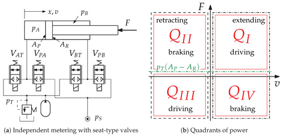
Figure 1.
Concept of independent metering for a hydraulic cylinder drive.
2.1. Operating Modes
Basically, the hydraulic drive is able to operate in all four power quadrants according to Figure 1b. Because the tank pressure level is lifted, an offset of in the load force must be considered for the correct power quadrant. Thus, if the effective power
is positive, then energy from the high-pressure supply is needed for the movement, and the drive operates in the quadrants or . When and the friction force plays only a minor role, the load force provides enough energy for the movement and the cylinder drive operates in a braking mode and thus in the power quadrants or It is a remarkable property of IM that in such cases no fluid from the high-pressure supply is necessary and the movement can be done only by connecting both chambers to the tank, which would not be possible with a conventional spool valve with coupled metering edges.
For a proper choice of operating mode, at least the sign of the load force must be known, which can be calculated from the pressure measurements in both cylinder chambers, which reads
under the assumption that the friction and the inertia play an inferior role, which is justified in the sense of the cybernetic approach and of the required accuracy for construction machines. Furthermore, the pressure measurements are necessary for the control strategy as presented below. Of course, pressure transducers require some additional installation costs, but currently for the opportunity of condition monitoring issues it is appropriate to measure the pressures in both cylinder chambers.
In Figure 2, the chamber pressures with regard to the range of the load force are depicted schematically. The diagram shows how the pressures and are defined for a desired load force. The dashed lines show the configuration where the rod-side chamber is connected to supply pressure constantly, which is often called high-side regeneration mode in the literature (see, for instance [4,7]). In fact, in this mode the maximum force is limited to , but on the other hand, the movement can be achieved at minimum flow rate. For those reasons, the configuration with the rod-side chamber constantly supplied with high pressure is also called rapid mode because in the unloaded case the maximum velocity can be achieved.
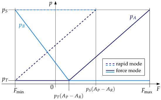
Figure 2.
Force graph.
In contrast to that, the solid lines in Figure 2 represent the so-called force mode, because the full range of load forces can be achieved. According to the actual power quadrant, the unloaded cylinder chamber is always connected to tank pressure, which means that the corresponding valve is completely opened in this operating mode.
It must be remarked that in case of the unloaded differential cylinder, the pressurized tank from Figure 1a leads to an extending hydraulic force when both chambers are connected to tank pressure. If the friction in the cylinder is low enough, then the piston rod can be extended without any power from the high-pressure port.
2.2. The Control Strategy
As mentioned in the introduction, the basic control strategy presented in this paper is a cybernetic open-loop concept, where the desired piston velocity is quasi-feedforward controlled by an inversion of the static flow characteristics of the actuated metering valve. The trajectories are assumed to be slow; in other words, no highly dynamic motion with regard to natural resonances of the drive system is intended. The trajectory error due to the occurrence of disturbances is corrected by the interaction of the human operator in a cybernetic manner.
The control of the CPS is a cyclic procedure implemented on a micro-processing unit with the desired piston velocity and the load force F as inputs. The basic flowchart is shown in Figure 3, which is evaluated with a cyclic time of . The initial state is assumed to be a standstill , thus the control is running in an idling cycle. When a movement is commanded by the operator, then in a first step the load force is evaluated using Equation (2). Then, the desired velocity according to the operators command designates the power quadrant. As already mentioned above, the basic control strategy is to completely open the relevant valve of the unloaded cylinder chamber. Consequently, the pressure in the loaded chamber is well defined and the velocity can be open-loop controlled by inverting the valve characteristics.
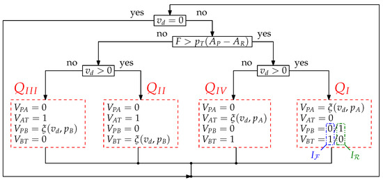
Figure 3.
Basic control strategy.
The variable represents the metering of the specific valve according to the operating mode. Assuming the ideal square root characteristics of the valves, the necessary valve opening according to the desired flow rate calculates to
where the relevant cross-section area of the metering chamber is , the relevant pressure drop according to the actual power quadrant is , the parameter is the nominal flow rate, and the parameter is the nominal pressure drop of the proportional valve. In reality, ideal square root characteristics of the valves cannot be assumed. Thus, the valves’ flow characteristics must be identified by measurements. Equation (3) represents an inversion of the well-known orifice equation. For this reason, the term inverted flow characteristics is used later in the corresponding section where the experimental investigations are presented. The specific parameters for all operating modes are listed in Table 1, where the state represents a standstill. Thus, all valve openings with regarding Figure 1a are defined. Consequently, an operation in the driving quadrants and results in a meter-in control, and a braking motion in quadrants and represents a meter-out control. Assuming that the correct operating mode is selected and the actual load force does not violate the specifications in Table 1, is fulfilled. As indicated in Figure 3 the quadrant can be divided in two substates and for rapid mode and force mode depending on the magnitude of the actual load force.

Table 1.
Control table of all operating points.
For the presented control strategy, an acceptable level of knowledge on the valve characteristics and the pressure measurements in both cylinder chambers are required. In case of a faulty pressure transducer, the load force and, furthermore, the metering variable from Equation (3) can no longer be calculated properly. However, even in such a case, the CPS is still able to maintain the basic movements just by neglecting the regenerative operating states. Thus, as in a conventional proportional drive system with coupled valve edges, an extending movement can be achieved by actuating the valves and with the metering
and for a retracting movement the valves and are metered as
with and as weight parameters.
3. Simulation
The simulation experiments for the CPS regarding Figure 1a were carried out in MATLAB/Simulink® with a dynamic model of the cylinder
and the flow rates and
regarding the operating states from Table 1 and the orifice function
representing the square root characteristics of a valve. (In the simulations, the square root function is approximated by a polynomial around the origin in order to guarantee the solvability of the numerical integration.) The numeric values of the corresponding parameters are listed in Table A1a.
For simplicity and clarity, a constant pressure supply for both the high pressure and tank pressure are assumed. Furthermore, in the very basic simulation experiments no significant inertial dead load () and a very low friction coefficient () are considered. The trajectory represents an extending movement at a constant piston velocity of followed by a short standstill and a retracting movement at the same speed. When the drive reaches its desired extending speed, a ramped load force is applied, which is maintained until the drive retracts the rod again. Then, the force is ramped down and finally, the unloaded drive decelerates to standstill. With this kind of trajectory and load force, the basic behavior in all four power quadrants is investigated.
3.1. Compressive Force
The most likely load for a differential cylinder drive is a compressive force. In Figure 4, the simulation results for a load force of are illustrated. In the upper diagram of Figure 4a, the piston velocity is illustrated, where the movement starts at the simulation time of . In most phases of the movement, the tracking shows a perfect match with the desired velocity due to an ideal inversion of the valve characteristics. However, a few spikes in the velocity occur, in particular, when the operating state of the drive changes.
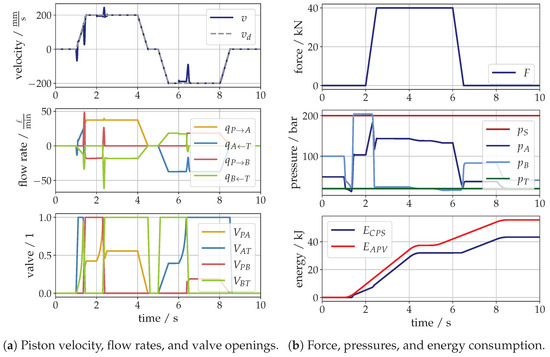
Figure 4.
Simulation of a compressive load force.
The first ripple in velocity occurs when the operating mode of the drive turns from standstill to extending direction at the very beginning of the movement. This jerky behavior is a settling effect of the initial chamber pressures, which can be seen in the middle diagram of Figure 4b. This effect only occurs, for instance, when the load changes during a standstill or when the direction of movement and the power quadrant change at the same time. Right after the beginning of the movement the drive operates in a braking mode, which can be seen in the lower diagram of Figure 4a. This results from the fact that a very low numeric value for the viscous damping parameter and a no stick–slip friction model was used in the simulations. Hence, the piston is extending, even when both chambers are connected to the elevated tank pressure. When the velocity and, thus, the friction force , the drive switches to rapid mode, i.e., to operating state according to Table 1. Entering this operating state, the switching of the valves results again in a velocity spike due to another pressure transients in both chambers. At a simulation time of a compressive force of (see the upper diagram in Figure 4b) is applied in form of a ramp. Consequently, the pressure in the piston-side chamber rises until the level is reached. Then, the drive changes its operating state to force mode , which means that the rod-side chamber is switched from high pressure to tank pressure and results in another velocity spike. After a certain movement under the applied load force, the drive decelerates with a limited slope in the velocity to standstill. In the lower diagram of Figure 4b, the energy consumption of the CPS compared to a conventional drive using a conventional valve with asymmetrical metering edges (APV) regarding the ratio of the cross-section areas of the cylinder. The inclination of the lines illustrates the power consumption, which means that in force mode, the CPS needs as much power as the conventional system. In all other situations, less energy is consumed by the CPS. This becomes more obvious when the movement in the opposite direction is started. In this phase of a retracting movement under a large compressive force, only braking is necessary and, thus, an operation in regarding Figure 1b takes place. In this case, almost no energy is consumed by the drive, because all chambers are connected to tank. Finally, when the load force is released again, the power consumption of both drives then coincide again.
3.2. Tensile Force
In contrast to the previous subsection, in the following a load case of a tensile force of is considered. The corresponding results are depicted in Figure 5 for the same trajectory of , as in the previous case. Until the load force is applied, the response of the system is identical as before. Then, the drive switches from operating state to , i.e., to power quadrant for braking. During this transition, the pressure signals in the middle diagram from Figure 5b show a large drop, resulting in a large peak in the piston velocity.
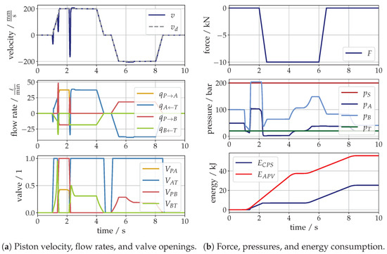
Figure 5.
Simulation of a tensile load force.
From this point, during the extending motion the drive acts in braking mode and the velocity is controlled by metering the fluid out of the rod sided chamber. The piston sided chamber is also connected to tank by a fully open valve . It is now important to mention that due to the large cross-sectional area in combination with the piston velocity, the flow rate over the valve leads to a corresponding pressure drop, which is in this case very close to the cavitation limit. Thus, for this kind of operating mode the valve size determines the maximum piston velocity with regard to an avoidance of cavitation.
In the braking mode, almost no energy is consumed by the CPS, as illustrated in the lower diagram of Figure 5b. When the moving direction changes, then the drive operates in , which represents a power retraction and, thus, as much power as with a conventional drive is consumed until the movement stops.
3.3. Toggling between Operating States
In the previous subsections, very basic and clean simulation experiments were considered in order to make the basic principle of operation clear. However, the velocity spikes in the presented results should be minimized. The main reason for the observed spikes is the transients of the pressures in both cylinder chambers due to the switching into another operating state. This may even be worse when additional (parasitic) dynamic effects are considered, which must be expected in reality. For instance, in the following the numeric value of the dead load, i.e., the inertia of the drive was increased from to , which is a realistic assumption. One may expect that additional inertia would result in a reduced dynamic response due to its low-pass behavior, but in this case, the opposite is true. This can be seen from the simulation results depicted in Figure 6a, where in the accelerating phase, the unloaded axis switches from braking mode to rapid mode. The additional inertia in combination with the compressibility in the chambers and, furthermore, with the response times of the valves the system starts to resonate and toggles between the states and according to Table 1.
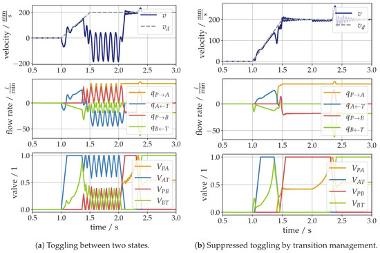
Figure 6.
Transitions between two states.
This undesirable behavior and, of course, all other critical transitions not mentioned here, must be avoided by a certain strategy where the switching between different operating modes is specifically controlled and optimized. This issue is not yet fully resolved and is still under ongoing investigations. As an example, in Figure 6b the response of the system with the same parameters is controlled with a kind of transition management using a certain valve timing depending on the pressures in both chambers which is not discussed in this paper. However, all meaningful transitions are
4. Experimental Investigations
One typical construction machine is an excavator. Its main operation areas are trench digging and grading, which represent different requirements on the control of the actuators. On the one hand, trench digging is a process where large movements under high loads are performed cyclically. Grading requires more sensitive and precise movement of the excavator arm under lower load forces. Thus, the requirements on the controllability and the efficiency are quite different for these types of load cycles. For this reason, an excavator was selected for the tests of the control strategy presented above with the focus on the controllability and efficiency in order to validate the applicability of the IM with CPS valves.
4.1. The CPS Valves
Basically, a CPS consists of four two-way proportional seat-type valves located in one valve block, such as depicted in Figure 7a, which is intended to be assembled as close to the actuator as possible. Furthermore, at least the sensors for both chamber pressures are located in the same CPS block. Of course, for a precise motion the supply pressure and the tank pressure must be known; however, those signals need not be measured directly in the valve block. In particular, in case of multiple actuators controlled with CPS only one high-pressure and one tank line must be lined to the actuator. This simplifies the piping significantly, such as, for instance, on the arm of an excavator. In fact, the block illustrated in Figure 7a is a prototype; however, in the final design an integration of the valves and the pressure transducers into the actuator would be an opportunity.
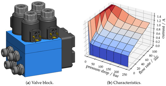
Figure 7.
CPS Valves.
The poppets of the CPS valves are designed with certain notches for realizing a fine control range at small openings. For this reason, the assumption of common square root characteristics is not sufficient and, therefore, the flow characteristics were derived from static flow measurements. In Figure 7b the inverted flow characteristics of one seat-type valve in the metering direction is illustrated. As already mentioned above, the term inverted means that the output is a valve current instead of a flow rate. In this context, the metering variable is related to the actual valve current, which calculates to . An observed hysteresis between opening and closing of the valves could be eliminated by superposing a dither signal to the valve current. Thus, for a desired flow rate at an actual pressure drop, the necessary current for the valve solenoid is known from the diagram.
The line at zero flow rate in Figure 7b indicates that a certain minimum current of approximately is necessary to open the valve, which might lead to the expectation of a kind of sensitivity with regard to a precise motion. However, the special mechanical design of the valves offers a certain fine control range, which improves the controllability at small valve openings. Thus, in the measurements, the movement at low velocities are of special interest. At the line of zero pressure drop the valve current is maximum, because this represents a kind of singularity in the characteristics, but this is not expected to occur often. However, those mentioned areas represent the sensitive operating points of the characteristics.
4.2. Test Facility
For the measurements, one actuator of the arm of a excavator depicted in Figure 8 was chosen. The actuator with the widest load specifications is the bucket stick cylinder, because apart from common compressive loads this actuator must also deal with tensile loads. For this reason, the bucket stick cylinder was equipped with the CPS for the measurements, as depicted in Figure 8b. In the experiments, the valve openings were measured; however, in a real application this would not be done for cost reasons. In fact, the CPS is open loop, and the human operator closes the control loop for motion control, but in order to achieve repetitive results, a closed-loop control was realized for the experiments. Therefore, the piston position of the bucket stick cylinder was also measured using a cord sensor and a simple P-controller with a certain trajectory feedforward were used.
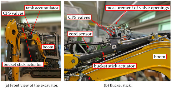
Figure 8.
Excavator.
For the pressure supply, an auxiliary section of the excavator was used in parallel with the original section for the bucket stick. Thus, in the experiments the bucket stick cylinder can be controlled either with the CPS or with the common proportional valve system. In the basic concept of the IM with seat-type valves, the tank pressure is elevated, and a gas-loaded accumulator is installed to compensate the different displacement volumes according to the different cross-section areas of the cylinder in brake mode (see Figure 1a). Instead of a pressure relief valve, in the experiments a check valve with a spring was used. The tank-side accumulator can be seen in Figure 8a.
In conventional excavators, different kinds of load sensing (LS) systems are installed in order to reduce the energy consumption. In the specific case, a sort of open-center system is used for every individual section of the excavator. As already mentioned, the bucket stick cylinder with the CPS is supplied through the auxiliary section. However, the control values for motion control using the CPS would not make sense in opening the auxiliary section. Furthermore, because only one actuator is under investigation, any kind of load sensing system would not make any sense at all, because in such a case the LS would keep the pressure as low as possible, which in turn would result in a maximum opening of the valves and the motion would only be controlled by the LS system. For these reasons, a constant pressure supply was realized for the bucket stick by a constant opening of the auxiliary section, and the supply pressure of 100 bar is controlled using a proportional pressure relief valve.
4.3. Measurements
In the following, the results for a motion under a tensile load of the actuator, in other words, a lifting and lowering of the unloaded bucket stick are presented in Figure 9. In the upper diagram of Figure 9a, the desired and the actual piston velocity according to a sinusoidal trajectory are presented. The velocity signal is calculated by the numeric gradient of the measured piston position, and thus, the signal is noisy. The trajectory tracking is acceptable; only a small dead zone around the zero-crossing of the velocity can be observed, which results from the minimum solenoid current for a proportional opening according to Figure 7b. In the middle diagram of Figure 9a, the individual valve openings are illustrated. The tank-side valve is constantly open, while the rod-side valves and are used for metering the piston velocity v. Lifting the bucket stick and lowering due to gravity represent operations in the power quadrants and , thus the piston-side valve is not actuated during the measurements. Sometimes a very short switch to power extending can be observed in the falling zero-crossing of the velocity. This is the case when the inclination of the bucket stick nearly vertical and thus the gravitational force is too low for a motion in brake mode. This can be also seen in the lower diagram from Figure 9a, where the pressures are illustrated. In a falling zero-crossing in the velocity, the pressures have their minima because the bucket stick is nearly at its lower point of inflection. In the lifting phase, the pressures rise to their maxima. Because power is necessary for lifting, the supply pressure has a certain subsidence due to the limited control accuracy of the constant pressure supply. In contrast to that, during the lowering of the bucket stick, no fluid from the pressure supply is necessary and thus the supply pressure is stable. This phase represents a braking mode where only fluid from the tank is required, which is provided by the tank-side accumulator. This can be clearly seen in Figure 9b, where the measured energy consumption is illustrated.
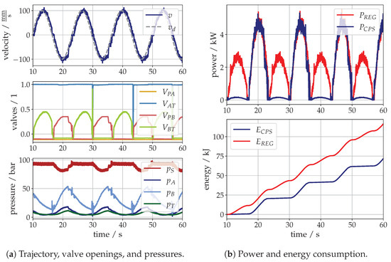
Figure 9.
Measurements of the unloaded bucket stick.
The blue line in the upper diagram shows the actual power consumption of the bucket stick cylinder controlled with the CPS. While during the lifting a peak consumption of approximately is required from the pump, in the lowering phase almost no power must be spent. For comparison, the red line in the upper diagram represents the power consumption of a conventional system according to Figure 10 with a so-called regenerative spool, which uses the fluid from the rod-side chamber during an extending motion under a tensile load as proposed, for instance, in the patent [22]. Thus, for the lowering of the bucket stick, only the displacement volume of the piston rod must be provided from the high-pressure supply system, i.e., by the pump. In the lower diagram in Figure 9b, the numerical integration of the power, i.e., the consumed energy of both drive configurations and , are opposed.
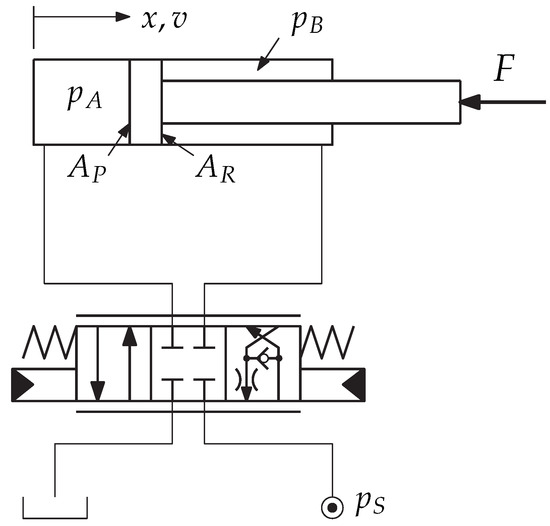
Figure 10.
Proportional valve with regeneration mode for a loss reduction at pulling loads ().
5. Discussion
The presented control of a hydraulic actuator using a CPS is an IM strategy, where the in- or out-flow of one chamber is metered while the relevant valve of the opposite chamber is fully open. The selection of the valve to be metered (i.e., fully opened) depends on the actual power quadrant, which is identified by pressure measurements. With this strategy, operations in braking mode can be realized efficiently only by using low pressurized oil from the tank. In this contribution, this effect was verified by simulations and measurements with a constant pressure supply. In a real situation, the excavator would be equipped with a sort of load sensing system. In such a case, the energy efficiency in power driving states is also improved because the valve resistance of the unloaded chamber is minimized by a full opening. Consequently, for the same load force, a lower supply pressure is necessary, which lowers the energy consumption of the drive compared to conventional proportional system with a single spool and coupled valve edges.
The presented measurements were focused on two specific power quadrants: the lifting and lowering of the bucket stick in order to verify the mode of efficient braking and, furthermore, to show that with the used valves a precise control is possible. Thus, the load was only determined by gravity, which does not represent a real situation. For a proof of applicability and the repeatability of results, different load conditions are necessary, which will be part of future investigation steps. In order to obtain meaningful results, it could be an opportunity to carry out and compare selected experiments from the literature.
The advantage of lower energy consumption is confronted with a higher number of components and sensors. However, the additional effort for the necessary pressure measurement must be reflected with regard to an improved capability in fault diagnosis. Furthermore, the logging and analysis of data captured from machines in the field enable a meaningful scheduling of maintenance as well as avoiding malfunctions of the machinery in advance. Moreover, with a CPS the characteristics of the drive can be adjusted with regard to the operating task or according to the demand of the operator. Even in case of a faulty pressure transducer the valves of the CPS can be controlled as a conventional valve system with coupled edges.
Compared to conventional proportional valve systems, a higher degree of freedom for efficient motion control leads also to a higher complexity in the control strategy. One of the most important challenges is the switching between the operating states, which must be somehow controlled in order to achieve smooth pressure transients. For instance, at the switching from rapid mode to force mode (see Figure 2) velocity fluctuations must be expected, because the pressure in the rod-side chamber changes rapidly by the magnitude of the supply pressure. Actually, the rapid mode is not necessary for a proper operation of the drive and impeding the rapid mode by software would reduce this effect. However, the transition from standstill to motion may also lead to non-smooth acceleration when the load changes in the rest position and thus pressure settling must be expected. Another problem occurs when the direction of the load changes during the movement because then the drive switches from driving to braking or vice versa, which may lead to larger pressure transients. Moreover, the switching between power quadrants in combination with the inertia of the load may result in toggling between operating states, which must be avoided entirely. As already mentioned before, the realization of smooth transitions between power quadrants is not fully resolved yet and thus is still a challenging part of ongoing investigations. Probably, in some cases a sort of hysteresis might be sufficient to suppress the toggling, but it is also possible that a more sophisticated decision strategy for a proper selection of the operating mode is required. In the end, the switching between 18 possible state transitions from Equation (13) must be optimized somehow, which seems to be challenging, even though in some applications some transitions might be neglected.
Regarding the most efficient installation on an excavator, the valve block of a CPS should be located directly at the cylinder. Thus, in case of multiple actuators, such as on the arm of an excavator, only one single supply line and one tank line must be installed, which reduces the piping costs significantly. One exemplary design study is illustrated in Figure 11. Because most of the valves are directly located at the actuator more space in the cabin is available, which can be used, e.g., for batteries, because the importance of electrically powered excavators is growing. Furthermore, due to a drive-by-wire concept, all the installation costs for hydraulic piloting can be saved. Moreover, the used valves for the CPS are seat-type valves, which are basically qualified for load holding; thus, costs for additional safety valves do not need to be spent.
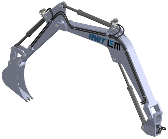
Figure 11.
Design study of an excavator arm fully equipped with CPS valves.
6. Conclusions
In this paper, the independent metering concept for the motion control of a hydraulic actuator using seat-type proportional valves with a fine control range was presented. For the cybernetic approach, the inverted static valve characteristics are used for the open-loop control of the desired movement. The human operator closes the control loop by correcting the trajectory using a proportional joystick. Simulations and measurements taught that with the CPS the energy consumption can be reduced significantly compared to a conventional valve control, because during braking operations no high-pressure fluid from the pump is required. A CPS uses seat-type proportional valves and thus load holding is also basically possible, which may avoid the installation of additional load holding valves. If the CPS valves are located directly at or are even integrated in the cylinder, then in case of multiple actuators, such as on the arm of an excavator, only one high-pressure supply line and one tank line must be spent, which gives room for further cost reduction. A big challenge is the switching between the operating states for a smooth transition. However, also the increased degree of complexity due to a higher number of components and, moreover, a higher number of degrees of freedom requires some further effort in development to fulfill the requirements for different fields of applications. The next steps are investigations on the full range of operating modes and its transitions for the bucket stick and furthermore, the equipment of all actuators of an excavator arm with CPS valve systems.
Author Contributions
Conceptualization, A.P., H.K. and P.F.; methodology, A.P., P.F. and H.K.; resources, P.F. and A.P.; software, H.K.; validation, P.F. and H.K.; writing—original draft preparation, H.K.; writing—review and editing, A.P., P.F. and H.K.; supervision, A.P.; project administration, A.P.; funding acquisition, A.P.; All authors have read and agreed to the published version of the manuscript.
Funding
This work has been supported by the COMET-K2 Center “Center for Symbiotic Mechatronics” of the Linz Center of Mechatronics (LCM) funded by the Austrian federal government and the federal state of Upper Austria.
Institutional Review Board Statement
Not applicable.
Informed Consent Statement
Not applicable.
Data Availability Statement
Data not publicly accessible. All relevant data is presented in the article. Data sharing is not applicable to this article.
Acknowledgments
The authors want to thank RWT company for the worthy cooperation and Linz Center of Mechatronics GmbH for the Open Access Funding.
Conflicts of Interest
The authors declare no conflict of interest.
Abbreviations
The following abbreviations are used in this manuscript:
| APV | Asymmetric Proportional Valve |
| CPS | Cybernetic Proportional System |
| IM | Independent Metering |
| LS | Load Sensing |
Appendix A

Table A1.
Parameters.
Table A1.
Parameters.
| (a) Simulation Model | |
|---|---|
| parameter | value |
| piston area | |
| rod-side area | |
| dead mass | |
| cylinder stroke | |
| viscous damping | |
| nominal flow rate | |
| nominal pressure drop | |
| valve response time | |
| dead volumes | |
| bulk modulus | |
| supply pressure | |
| tank pressure | |
| (b) Bucket Stick Cylinder Drive | |
| parameter | value |
| piston diameter | |
| rod-side area | |
| cylinder stroke | |
| nominal flow rate | |
| nominal pressure drop | |
| supply pressure | |
| tank pressure | |
References
- Merritt, H.E. Hydraulic Control Systems; John Wiley & Sons: Hoboken, NJ, USA, 2019. [Google Scholar]
- Reiners, E.A.; Ufheil, S.T. Independent Metering Valve Assembly for Multiple Hydraulic Load Functions. U.S. Patent 2002/0148223 A1, 19 July 2005. [Google Scholar]
- Kleitsch, A.J.; Ma, P.; Brinkman, J.L.; Sorokin, M. Hydraulic System including Independent Metering Valve with Flowsharing. U.S. Patent 2016.0312807A1, 28 November 2017. [Google Scholar]
- Shenouda, A. Quasi-Static Hydraulic Control Systems and Energy Savings Potential Using Independent Metering Four-Valve AssemblyConfiguration. Ph.D. Thesis, Georgia Institute of Technology, Atlanta, GA, USA, 2006. [Google Scholar]
- Shenouda, A.; Book, W. Optimal Mode Switching for a Hydraulic Actuator Controlled with Four-Valve Independent Metering Configuration. Int. J. Fluid Power 2008, 9, 35–43. [Google Scholar] [CrossRef]
- Abuowda, K.; Noroozi, S.; Dupac, M.; Godfrey, P. Model Based Driving Analysis for A novel Stepped Rotary Flow Control Valve. IFAC-PapersOnLine 2019, 52, 549–554. [Google Scholar] [CrossRef]
- Abuowda, K.; Okhotnikov, I.; Noroozi, S.; Godfrey, P.; Dupac, M. A review of electrohydraulic independent metering technology. ISA Trans. 2020, 98, 364–381. [Google Scholar] [CrossRef] [PubMed]
- Liu, W.; Li, Y.; Li, D. Review on Inlet/Outlet Oil Coordinated Control for Electro-Hydraulic Power Mechanism under Sustained Negative Load. Appl. Sci. 2018, 8, 886. [Google Scholar] [CrossRef]
- Ahamad, M.; Dinh, Q.T.; Nahian, S.A.; Ahn, K.K. Development of a New Generation of Independent Metering Valve Circuit for Hydraulic Boom Cylinder Control. Int. J. Autom. Technol. 2015, 9, 143–152. [Google Scholar] [CrossRef]
- Nguyen, T.H.; Do, T.C.; Ahn, K.K. A Study on a New Independent Metering Valve for Hydraulic Boom Excavator. Appl. Sci. 2022, 12, 605. [Google Scholar] [CrossRef]
- Wydra, M.; Geimer, M.; Weiss, B. An Approach to Combine an Independent Metering System with an Electro-Hydraulic Flow-on-Demand Hybrid-System. In Proceedings of the Linköping Electronic Conference Proceedings, Linköping, Sweden, 7–9 June 2017. [Google Scholar] [CrossRef]
- Su, W.; Ren, W.; Sun, H.; Liu, C.; Lu, X.; Hua, Y.; Wei, H.; Jia, H. Data-Based Flow Rate Prediction Models for Independent Metering Hydraulic Valve. Energies 2022, 15, 7699. [Google Scholar] [CrossRef]
- Koivumäki, J.; Zhu, W.H.; Mattila, J. Energy-efficient and high-precision control of hydraulic robots. Control Eng. Pract. 2019, 85, 176–193. [Google Scholar] [CrossRef]
- Li, C.; Lyu, L.; Helian, B.; Chen, Z.; Yao, B. Precision Motion Control of an Independent Metering Hydraulic System with Nonlinear Flow Modeling and Compensation. IEEE Trans. Ind. Electron. 2021, 69, 7088–7098. [Google Scholar] [CrossRef]
- Kikuuwe, R.; Okada, T.; Yoshihara, H.; Doi, T.; Nanjo, T.; Yamashita, K. A Nonsmooth Quasi-Static Modeling Approach for Hydraulic Actuators. J. Dyn. Syst. Meas. Control 2021, 143, 121002. [Google Scholar] [CrossRef]
- Choi, K.; Seo, J.; Nam, Y.; Kim, K.U. Energy-saving in excavators with application of independent metering valve. J. Mech. Sci. Technol. 2015, 29, 387–395. [Google Scholar] [CrossRef]
- Linjama, M.; Huova, M.; Boström, P.; Laamanen, A.; Siivonen, L.; Morel, L.; Walden, M.; Vilenius, M. Design and Implementation of Energy Saving Digital Hydraulic System. In Proceedings of the Tenth Scandinavian International Conference on Fluid Power, SICFP’07, Tampere, Finland, 21–23 May 2007. [Google Scholar]
- Ketonen, M.; Linjama, M. Simulation study of a digital hydraulic independent metering valve system on an excavator. In Proceedings of the Linköping Electronic Conference Proceedings, Budapest, Hungary, 18–20 September 2017. [Google Scholar] [CrossRef]
- Ketonen, M.; Linjama, M. Digital Hydraulic IMV System in an Excavator - First Results. In Proceedings of the 16th Scandinavian International Conference on Fluid Power, SICFP’19, Tampere, Finland, 22–24 May 2019. [Google Scholar]
- Huova, M.; Tammisto, J.; Linjama, M. Open-loop Independent Metering Control of a Multi-DOF Forwarder Boom. Int. J. Fluid Power 2020, 21, 147–168. [Google Scholar] [CrossRef]
- Kosean, W. Electro-Hydraulic Valve. EP1614947 (A1), 11 January 2006. [Google Scholar]
- Chung, T.S.; Lee, Y.G. Variable-Regeneration Directional Control Valve for Construction Vehicles. US5862831, 26 January 1999. [Google Scholar]
Disclaimer/Publisher’s Note: The statements, opinions and data contained in all publications are solely those of the individual author(s) and contributor(s) and not of MDPI and/or the editor(s). MDPI and/or the editor(s) disclaim responsibility for any injury to people or property resulting from any ideas, methods, instructions or products referred to in the content. |
© 2023 by the authors. Licensee MDPI, Basel, Switzerland. This article is an open access article distributed under the terms and conditions of the Creative Commons Attribution (CC BY) license (https://creativecommons.org/licenses/by/4.0/).