Article

Achieving Full Forward Flow of Valveless Piezoelectric Micropump Used for Micro Analysis System

State Key Laboratory of Robotics and System, Harbin Institute of Technology, Harbin 150001, China
*
Authors to whom correspondence should be addressed.
Actuators 2022, 11(8), 218; https://doi.org/10.3390/act11080218
Submission received: 6 July 2022 / Revised: 26 July 2022 / Accepted: 1 August 2022 / Published: 4 August 2022
(This article belongs to the Special Issue Piezoelectric Ultrasonic Actuators and Motors)

Abstract

:
The valveless piezoelectric micropump has the advantages of simple structure, high precision and low cost, which can realize the directional transport of micro-fluid and wildly be applied in a micro analysis system. However, backflow at the outlet cannot be avoided due to the limitation of its working mechanism. Large reflux rate can increase the volume control accuracy per cycle, but reduces the stability of the micro analysis system. In order to achieve a full forward flow, which reduce the influence of backflow on the system’s stability, the reflux characteristics of the designed valveless piezoelectric micropump were studied. The condition proposed, which should be satisfied for obtaining full forward flow, is that the reflux rate should be less than 50%. The influence of relations between the size of the key structures and pumping characteristics are established, and the references for structural parameter selection to reduce backflow and achieve full forward flow are given. This paper highlights the methods of controlling the pumping performance and achieving full forward flow, based on structural parameter selection analysis and adjusting excitation. The reflux rate can be reduced to 5% when the inlet angle is increased to 9°. The experimental results verify the validity of the obtained results and the proposed methods of control. This work provides important references for applying valveless piezoelectric micropumps in micro analysis and precision-driven systems.

1. Introduction

Valveless piezoelectric micropumps can accurately drive micro-fluid and are based on the change in cavity volume produced by the vibration of the piezoelectric actuator. The piezoelectric actuator has the advantages of high control accuracy, simple structure and good stability, and is widely used in many fields that are precision-driven [1,2,3,4,5,6]. Ashraf et al. [7] proposed a transdermal drug delivery system based on the valveless piezoelectric pump and hollow microneedles, and the performance was studied by simulations and experiments. Cui et al. [8] presented a drug delivery system for the in vitro injection of diabetics based on the valveless piezoelectric pump, and the influence of key parameters on the pump’s performance were analyzed based on this proposed model. Su et al. [9] studied the performance of a valveless piezoelectric micropump used for pumping drug particles, and obtained the influence of excitation and particle size on the pump’s performance. Dinh et al. [10] developed a valveless piezoelectric micropump with a silicon hotwire as a flow sensor, which can be used for lab-on-a-chip gas sensing analysis. Azarbadegan et al. [11] presented a parallel valveless piezoelectric micropump and the viability of the pumping cells was examined. Zhang et al. [12] proposed a novel valveless piezoelectric pump with a y-shape, tree-like construction for electronic chip cooling, and the influence of driving frequency on flow rate was analyzed. Yueh et al. [13] designed a cooling system for mobile systems-on-chips based on a valveless piezoelectric micropump and proved the system’s efficiency by experiments. Zhang et al. [14] proposed a ring-type valveless piezoelectric micropump for use in methanol fuel cells and obtained the optimal design parameters based on the proposed theoretical model. Ma et al. [15] developed a bi-cell proton exchange membrane fuel cell based on a valveless piezoelectric micropump and optimized a groove-designed piezoelectric actuator to improve the performance of the cell. Hu et al. [16] proposed a novel suction cup, which could be applied in robotics to achieve miniaturization, based on the valveless piezoelectric pump, and simulations were carried out to verify the performance.
For micropumps used in lab-on-a-chip or precision-driven systems, they require the performance of a large outflow rate and velocity to meet the demands of high pumping power. Researchers usually improve the pumping power by proposing new structures, optimizing structure sizes or optimizing the excitation methods. He et al. [17] proposed a bidirectional valveless piezoelectric micropump with one piezoelectric actuator, which improved the volume efficiency and achieved a better flow rate with different excitation parameters. Kan et al. [18] proposed a novel piezoelectric pump with a self-sensing mechanic for sensing the flow rate, which can achieve a closed-loop control. Wang et al. [19] found that pump performance was also critically influenced by the vibration chamber of the valveless micropump, and the authors proposed high-performance pump structures. Li et al. [20] proposed a photothermal micropump that could be applied in the multiplexed on-chip transport of substances, and the pumping performance was able to be remotely adjusted. Shoji et al. [21] proposed an easy method of fabricating a diaphragm micropump by using a polymer actuator and a good performance was observed in the experiments. Bowser et al. [22] designed a peristaltic micropump actuated by piezoelectric bimorph cantilevers, and they proposed methods to obtain high pump performance. Wang et al. [23] proposed the method of applying umbrella-shaped valves in piezoelectric micropumps to obtain a high flow rate. Walker et al. [24] proposed a power-free, paper-based passive pump, which can be used to generate a controllable flow of complex biofluids; a good pumping performance was observed by tests. Park et al. [25] integrated micropumps with valves to realize flow path and flow rate control through finger actuation. Andersson et al. [26] proposed a valveless micropump which could pump viscous fluids, solutions containing beads and living cells effectively, which was accomplished by using a silicon-glass stack in a new process. Ma et al. [27] designed a valveless piezoelectric micropump with an inner rib plate and studied the influence of structure sizes on the pumping performance. Bercovici et al. [28] proposed the method of applying elecroosmotic pumping for the dynamic control of capillary flow in paper-based devices, and the experimental results proved the validity of the method. Lin et al. [29] proposed an acoustic micropump, which can be used for single-cell trapping and the pump performance was discussed. Lee et al. [30] proposed a hydrostatic, pressure-driven passive micropump, enhanced with an autofill function, and it achieved a steady pump performance over a long period of time. Li et al. [31] analyzed the influence of key structure sizes on the performance of a valveless piezoelectric pump through simulations, and proposed suitable structure dimensions that could obtain a higher flow rate. Park et al. [32] proposed a hydrogel-driven suction pump that could achieve a high flow rate, and the validity of applying the designed pump for portable power generators was proven by tests. Chatterjee et al. [33] analyzed the influence of voltage amplitude and frequency on the performance of a designed valveless piezoelectric pump, and the authors gave an optimum voltage amplitude and frequency for obtaining both high flow rate and back pressure. Valveless piezoelectric micropumps, which have the advantages of high control accuracy, simple structure and good stability, are one of the common methods used for the directional precision transport of micro-fluids. Garcia-Cordero et al. [34] proposed a micropump integrated with valves and experiments demonstrated that the device could be used for implementing controlled cell-staining assays.
As the directional flow of the valveless piezoelectric micropump is produced by the flow difference between the pumping and suction modes, processes that are generated by the periodic volume change of cavity, backflow is hard to avoid [35]. The backflow effect has been ignored in the literature, as the main purpose of the studies are to obtain high outlet flow rate and pressure. When a valveless piezoelectric micropump is applied in a lab-on-chip system, too much backflow causes several vortices. The vortices reduce the stability of the micro analysis system. Effective inhibition of backflow to achieve a fully forward flow can improve the pumping efficiency and the performance of the analysis system where the valveless micropump is applied in.
Backflow cannot be avoided due to the working mechanism, but by controlling excitation and by optimizing the structure sizes, full forward flow can be achieved to reduce the influence of backflow on pumping performance. In order to make the valveless piezoelectric micropump stable and controllable for use in micro precision analysis and precision drive systems, the reflux characteristics and the methods for inhibiting backflow to obtain full forward flow were examined in this study. By studying the pumping mechanism of the valveless piezoelectric micropump, the conditions for obtaining a full forward flow are listed. The influence of voltage amplitude, inlet length, outlet length, cavity depth, inlet angle, and outlet angle were obtained, with respect to the mechanism’s pumping volume per cycle, total pumping volume and reflux rate. This paper proposes methods of structure optimization for inhibiting backflow to obtain a full forward flow and the required pump performance. The validity and credibility of the obtained results and proposed controlling methods were verified by experiments.

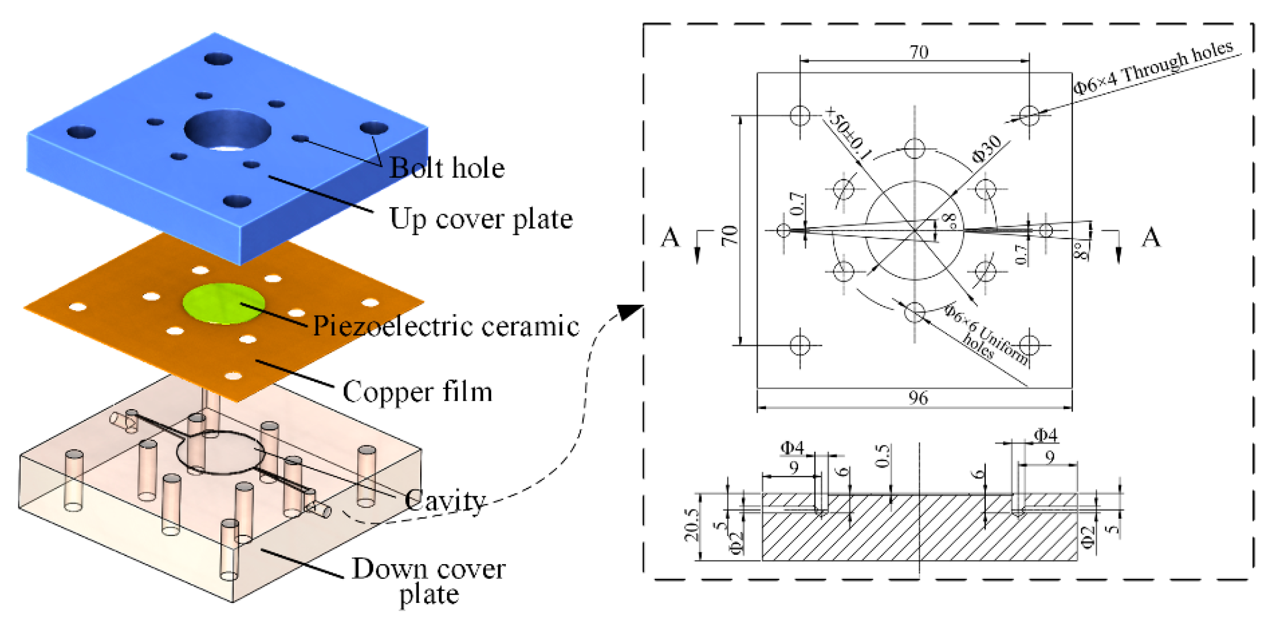
2. Structure of Micropump

Firstly, a valveless piezoelectric micropump, whose inlet and outlet adopt a wedge-shaped groove structure, was designed as shown in Figure 1. The micropump is composed of an up cover plate, piezoelectric ceramic, copper film, and down cover plate with cavity. The piezoelectric ceramic is adhered to the copper film to form the piezoelectric actuator. The three components are clamped together by bolts. The down and up cover plates, made of stainless steel, are created by CNC machine processing. The dimensions of the cavity and the corresponding down cover plate are shown in Figure 1 (right) The PZT ceramic adopts the d31 mode, and its diameter and thickness are 25 and 0.2 mm, respectively. The PZT ceramic (PZT-5H) is polarized along the thickness direction. The copper sheet is made of red copper, and its thickness is 0.1 mm. The working principle can be described as shown in Figure 2, where q1 and q2 are the inflows at the inlet and outlet during the sucking process, and q1 and q2 are the outflows at the inlet and outlet during the pumping process. The piezoelectric actuator deforms when periodic voltages are applied, which results in the periodic change of the cavity volume. Along with the volume change of the cavity, the whole working process of the designed piezoelectric micropump includes sucking and pumping modes.

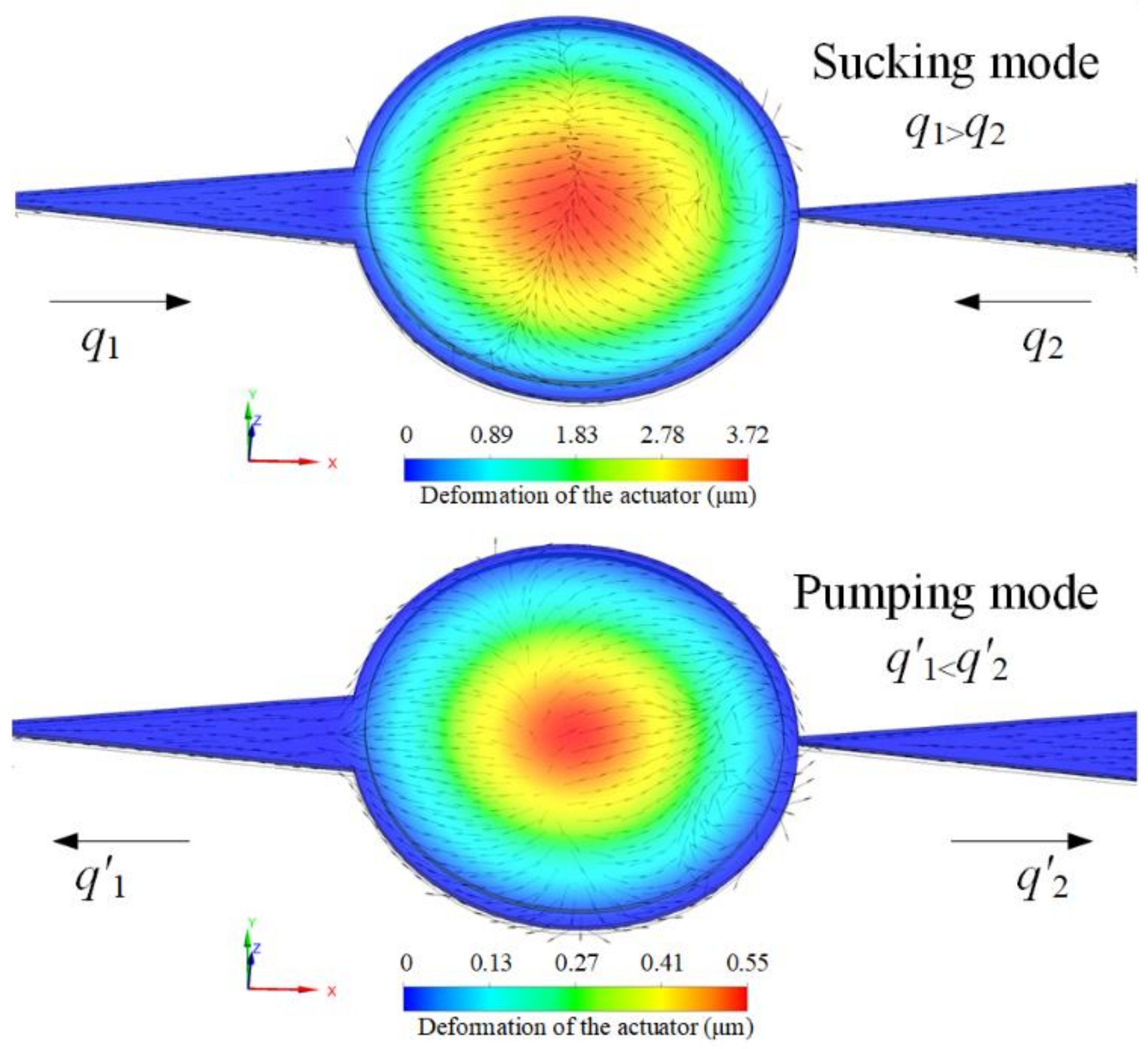
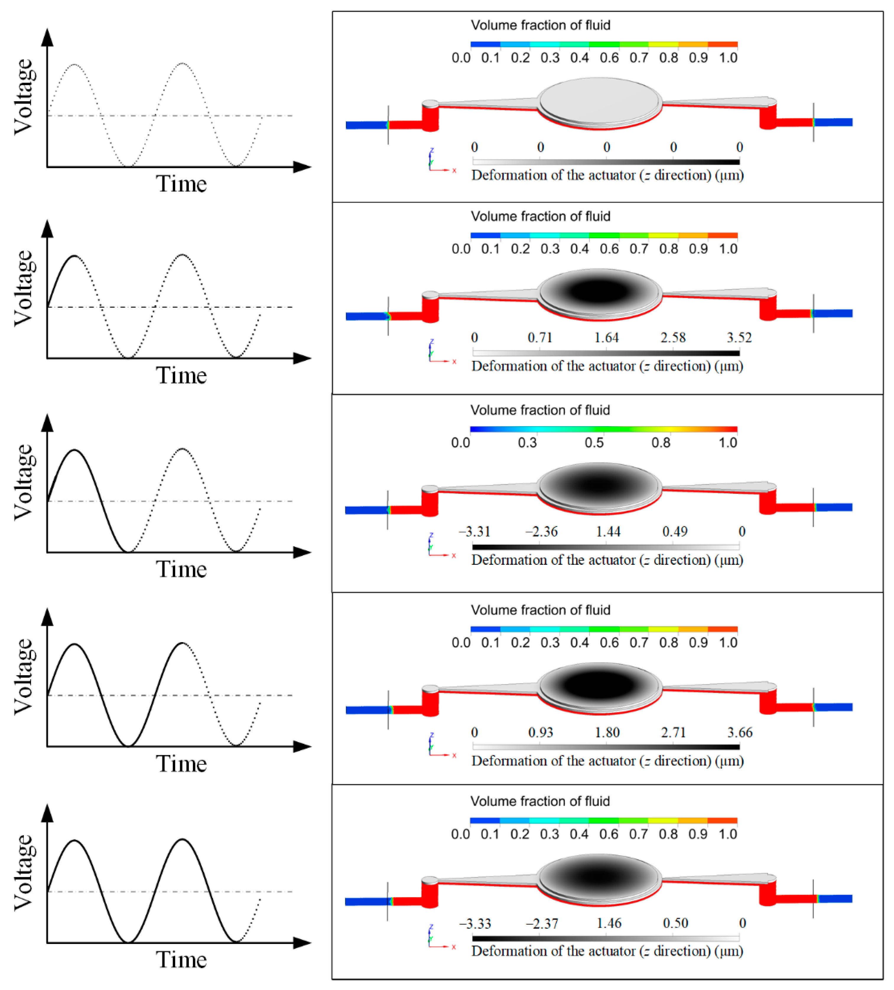
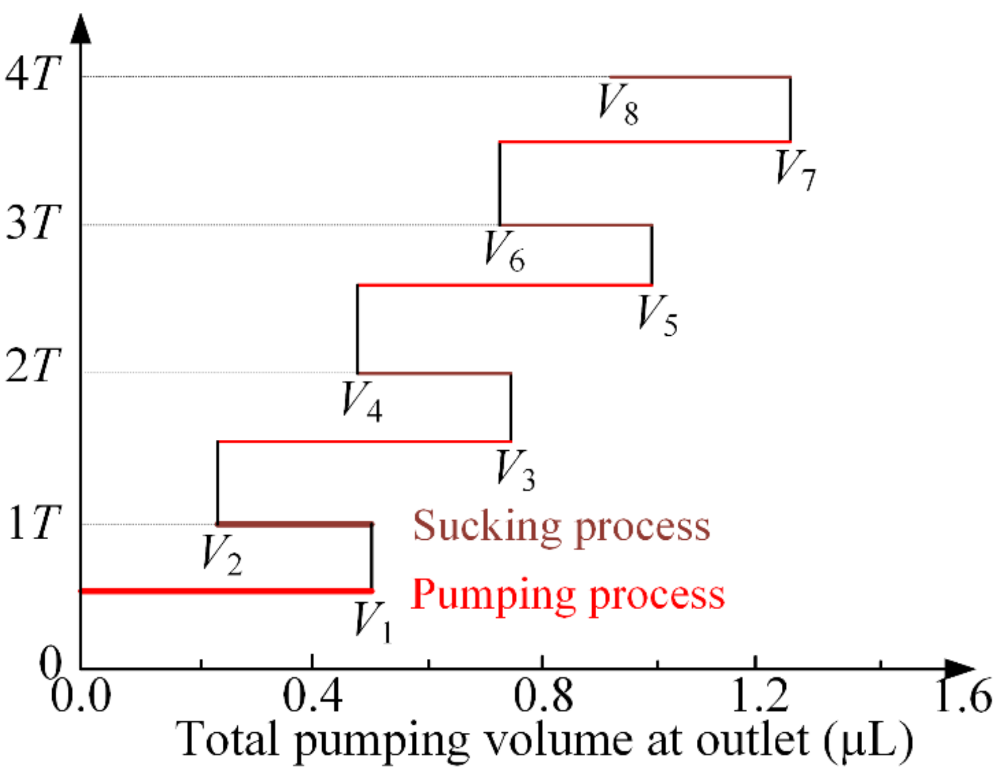
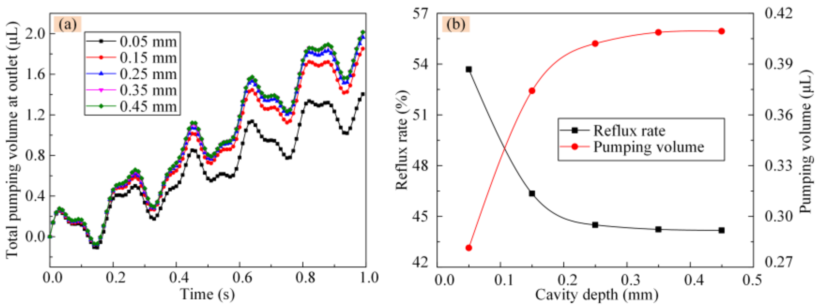
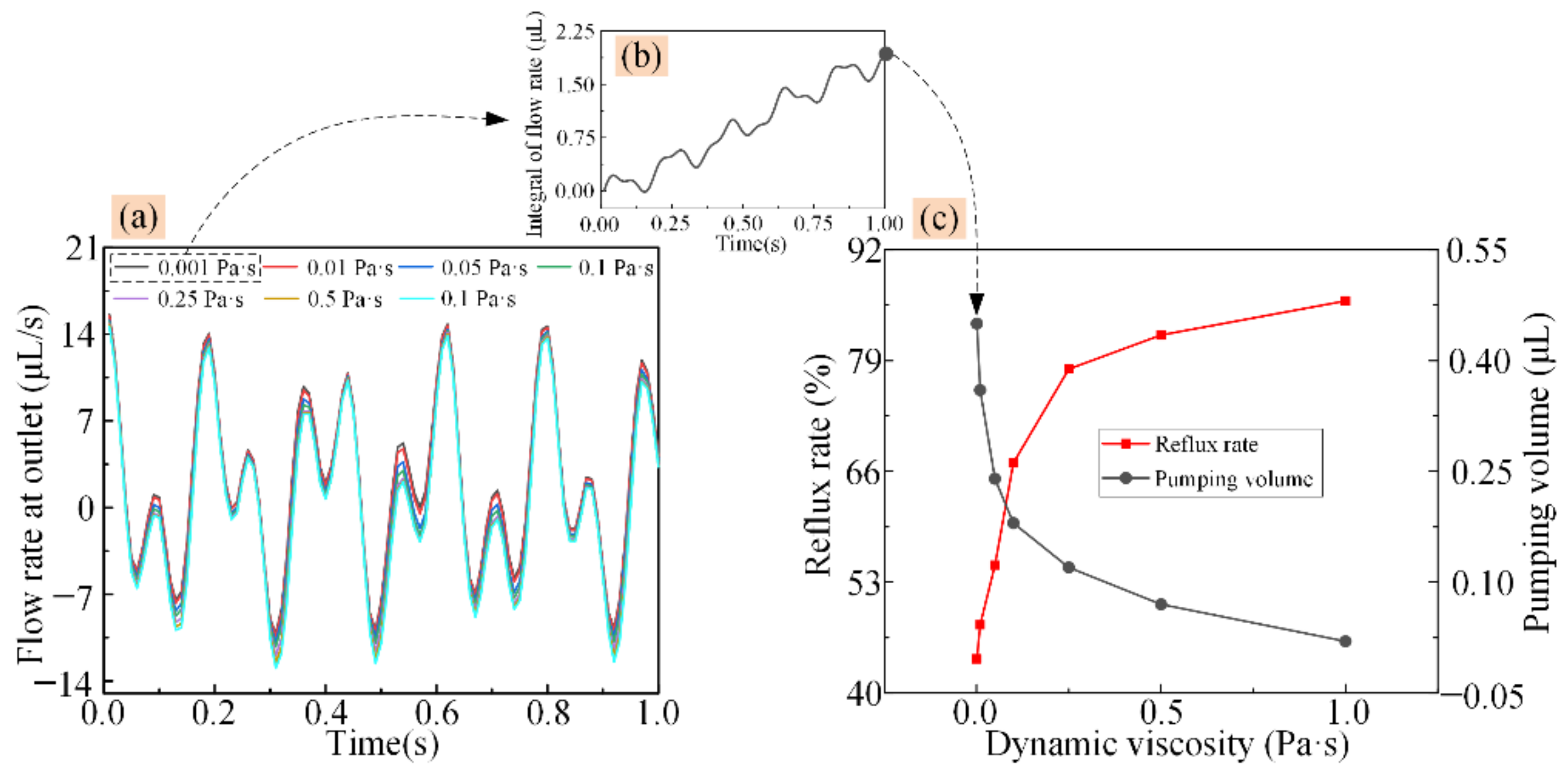
3. Simulation Procedure and Results

The volume of the cavity expands during the sucking process, and fluid flows into the cavity from the inlet and the outlet. Due to the influence of the wedge-shaped groove, the route loss created is less when the fluid flows through the inlet than when it flows through the outlet. Thus, in this process, the volume of fluid being sucked into the cavity is larger through the inlet than through the outlet. Conversely, during the pumping process, the volume of fluid pumping out of the cavity through the outlet is larger than that of through the inlet. The net pumping flow during the whole working process can be calculated as q2q2.
The piezoelectric micropump designed in this study is mainly used for precise fluid supply, where the piezoelectric actuator works in a non-resonant state, and sinusoidal excitation is applied. When a periodic voltage is applied, the pumping characteristics of the piezoelectric micropump are shown in Figure 3. When a positive voltage is applied, the piezoelectric micropump operates in the sucking mode. The piezoelectric actuator bends outward, which results in the cavity volume increasing and fluid flowing into the cavity from the inlet and outlet. In this process, the volume of fluid flowing into the cavity at the inlet is larger than that of at the outlet. When a negative voltage is applied, the piezoelectric micropump operates in the pumping mode. The piezoelectric actuator produces an inner bending deformation, and the fluid flows out of the cavity through both the inlet and outlet. In this process, more fluid is pumped out through the outlet than through the inlet.
Using a continuous periodic voltage, a directional flow is produced. Due to the limitation of the working mechanism, it is difficult to avoid backflow in a valveless piezoelectric micropump. The total pump flow at the outlet can be described in Figure 4a, where point A and C represent the maximum total pumping volumes, while B and D represent the minimum total pumping volumes. For reducing the influence of backflow on the stability and controllability of the micro analysis system, we expect that point D should be behind point A to realize the full forward flow, as described in Figure 4b. The condition to realize the full forward flow is:
q 2 q 2 + q 2 q 2 > q 2
That is,
q 2 < 0.5 q 2
We define q2/q2 as the reflux rate. That is, when the reflux rate is less than 50%, full forward flow can be realized.
The key factors that affect the pumping characteristics of the valveless piezoelectric micropump are the excitation parameters and structure sizes. In order to obtain the methods for controlling the pumping performance and achieving a full forward flow, the influence of inlet length, outlet length, cavity depth, inlet angle, outlet angle, and fluid viscosity on the pumping characteristics were studied.

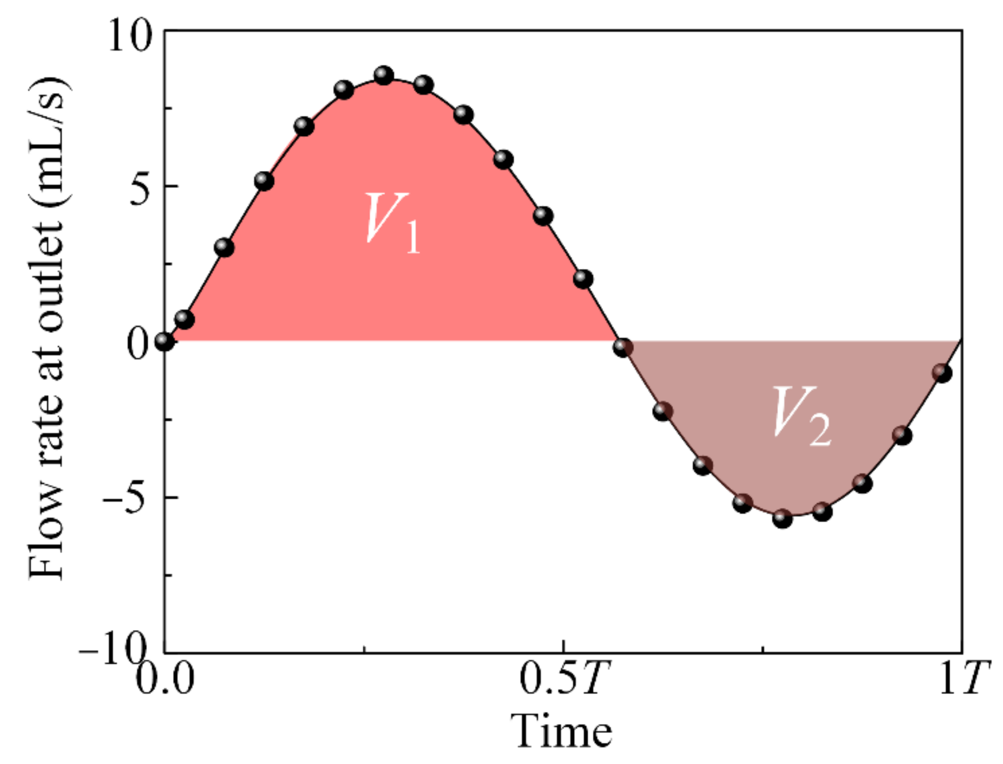
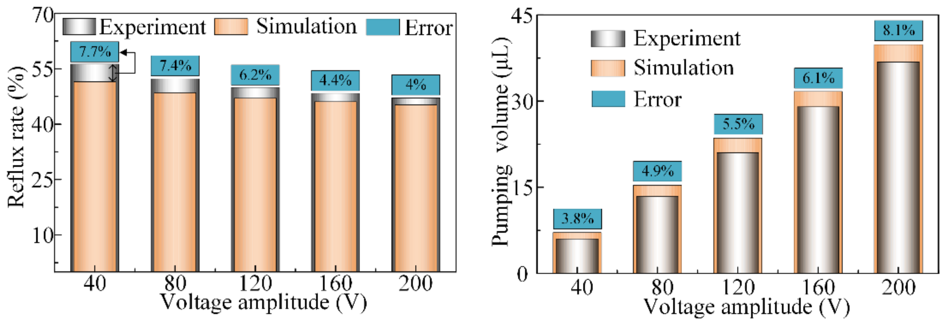
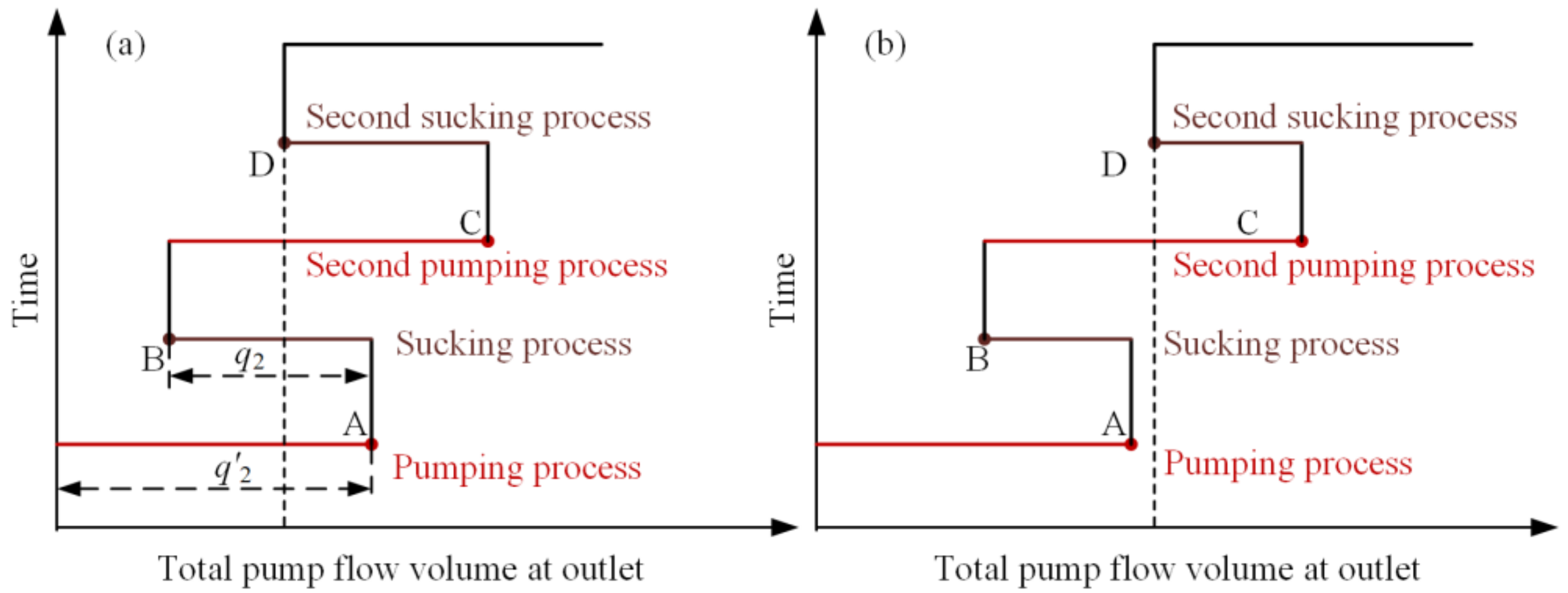
4. Pump Characteristics
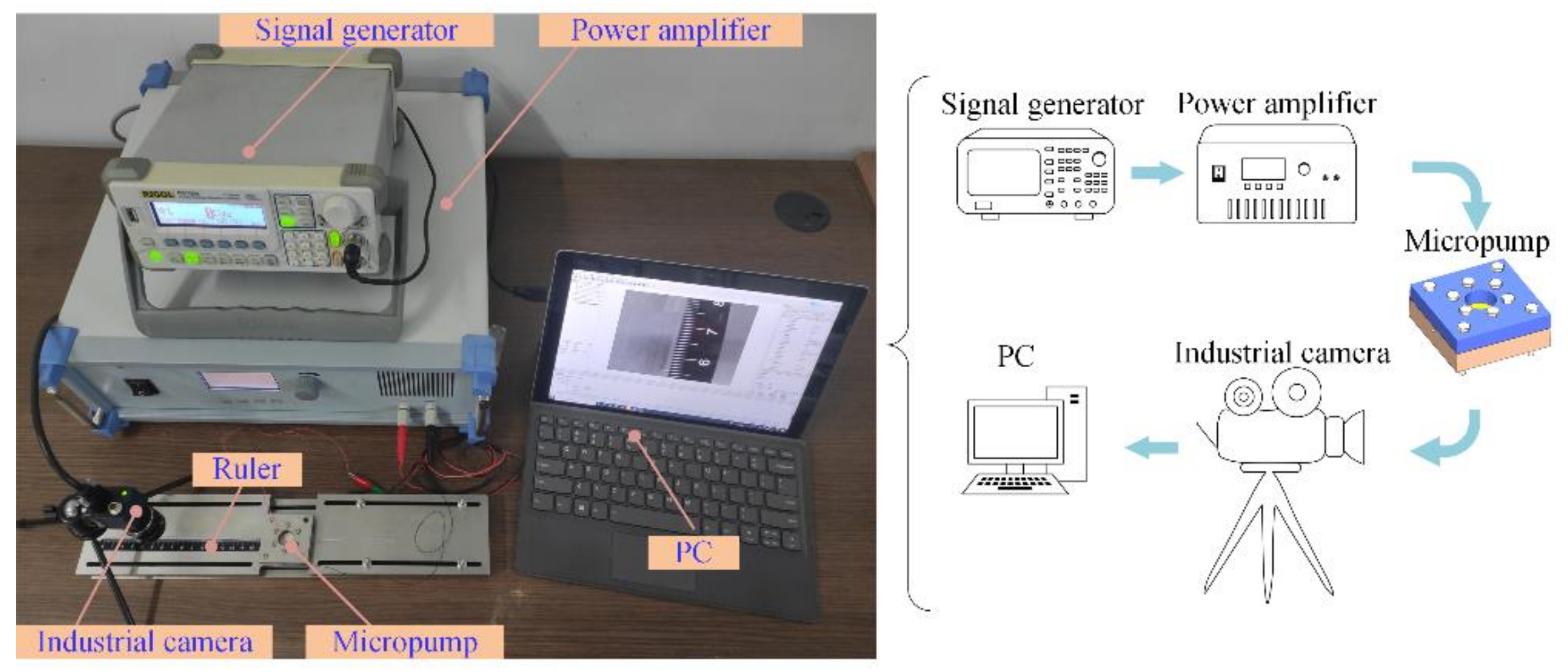
In this work, the principle of the single variable was adopted, and the initial value of each parameter is shown in the Table 1. When the relationship between a certain parameter and the pumping characteristics was studied, the other parameters remain unchanged. In order to produce more effective results, when the influence of outlet (or inlet) angle on the pumping performance were analyzed, the inlet (or outlet) angle was set to zero.
The pumping characteristics were mainly obtained based on the coupling analyses, which were carried out using the finite element analysis software ANSYS Workbench. The results of the flow rate at the outlet that varies with time was obtained, and is shown in Figure 5, where T represents the period. It can be observed that when the periodic voltages were applied on the piezoelectric actuator, the flow rate at the outlet changed periodically, and the peak value of the outflow was larger than the peak value of the inflow. The total pumping volume at the outlet was obtained by integrating the flow rate, as is shown in Figure 6, where V1, V3, V5, and V7 represent the maximum total pumping volumes, and V2, V4, V6, and V8 represent the minimum total pumping volumes.
In a single period, the pumping volume of the designed piezoelectric micropump can be calculated as:
Q = V 8 / 4
The reflux rate can be calculated as:
η = V 1 V 2 / V 1 + V 3 V 4 / V 3 V 2 + V 5 V 6 / V 5 V 4 + V 7 V 8 / V 7 V 6 / 4
When the outlet angle was at 0°, the total pumping volumes at the outlet of the piezoelectric micropump with different inlet angles are shown in Figure 7a. When the angles of the inlet and outlet were both zero, the total pumping volume changed periodically between fixed values. This was due to the created route loss along the inlet and outlet being the same. When the inlet angle was not zero, the total pumping volume increased with time. In addition, as the inlet angle increases, the fluctuation of the curve weakens.
The reflux rates and pumping volumes of the piezoelectric micropump, based on different inlet angles, are shown in Figure 7b. When the angles of the inlet and outlet were both zero, the reflux rate was almost 100% and the pumping volume in one period was nearly zero. That is, directional fluid transportation cannot be realized in this situation. When the inlet angle was larger than zero, the reflux rate decreased with the increase of the inlet angle, and the reflux rates were less than 50% when the inlet angles were larger than 3°. The reflux rate was reduced to 5% when the inlet angle was increased to 9°. However, the reflux rate was stable when the inlet angle continued to be increased. Thus, a small reflux rate can be obtained by increasing the inlet angle, achieving an efficient full forward flow.
The total pumping volumes of the piezoelectric micropump, with different inlet lengths, are shown in Figure 7c. An increase in the inlet length resulted in an increased fluctuation of the result curve and a gradual decrease of the total pumping volume. The reflux rates and pumping volumes under different conditions are shown in Figure 7d, based on the obtained results. There was a gradual increase in reflux rate with the increase of inlet length, and the reflux rates were all less than 50% when the inlet lengths were less than 25 mm. Additionally, a reflux rate below 33% could be obtained when the inlet length was less than 10 mm. In one period, the pumping volume decreased with the increase of the inlet length, with a volume control accuracy of less than 0.38 μL per cycle; this was obtained when the inlet length was larger than 30 mm. Therefore, when the control accuracy meets the necessary conditions, a full forward flow and large pumping volume can be achieved by reducing the inlet length.
The total pumping volumes at the outlet are shown in Figure 7e, based on the variations in the outlet angles. When the inlet angle was zero, the resulting curves of the total pumping volume largely fluctuate. As the outlet angle was increased, the total pumping volumes gradually decreased. The reflux rates and pumping volumes under different conditions are shown in Figure 7f. When the inlet angle was zero, nearly all of the reflux rates were larger than 50%, and the rates increased with the increase of the outlet angle. We surmised that to achieve full forward flow, the inlet angle cannot be zero, and a small outlet angle should be selected to reduce the reflux rate, thereby increasing the pumping efficiency. Additionally, the pumping volume decreased with the increase in the outlet angle, and the volume control accuracy of nearly 0.16 μL per cycle can be obtained when the outlet angle is greater than 15°. That is, when the required full forward flow is achieved, high volume control accuracy can be obtained by moderately increasing the outlet angle.
The total pumping volumes of the piezoelectric micropump, varied with different outlet lengths, are shown in Figure 7g. With the increase in outlet length, the total pumping volume increased and the curve fluctuation intensity gradually decreased. The reflux rates and pumping volumes were obtained based on the results, as shown in Figure 7h. An increase in outlet length gradually decreased the reflux rate, and when the outlet length was more than 15 mm, the reflux rate decreased below 50%. The pumping volume in one period increased along with the increase in outlet length. Thus, to achieve a full forward flow and high pumping efficiency, a large outlet length should be selected to reduce the corresponding reflux rate.
The pumping characteristics of a valveless piezoelectric micropump are also influenced by the cavity depth. The total pumping volumes varies with different cavity depths, and is shown in Figure 8a. An increase in the cavity depth resulted in an increase in the total pumping volume, and also resulted in the curve fluctuation intensity decreasing. The result curves of total pumping volume, when the reflux rates and pumping volumes were under different conditions, are shown in Figure 8b. An increase in cavity depth resulted in the reflux rate gradually decreasing when the thickness was less than 0.25 mm, and then slowly increasing. The reflux rate was less than 50% when the cavity depth was larger than 0.1 mm. The pumping volume in one period increased with the increase in the cavity depth, and it was stable when the cavity depth ranged larger than 0.25 mm. Therefore, a larger cavity depth should be implemented to achieve a full forward flow and high pumping efficiency. However, when the cavity depth was larger than 0.25 mm, the effect of the change in cavity depth weakened.
The flow rates of different fluid viscosities at the outlet, varied with time, are shown in Figure 9a. The total pumping volume at the outlet for the fluid viscosities of 0.001 Pa·s was obtained by integrating the flow rate, and is shown in Figure 9b. The results of the reflux rates and pumping volumes in a given period, varied with different viscosities, are shown in Figure 9c. The pumping volume decreased as the fluid viscosities increased, and when a fluid with a viscosity of 1 Pa·s is pumped through, a volume control accuracy of less than 20 nL per cycle can be observed. The reflux rate increased along with the increase in the viscosity.

5. Experiments

To verify the obtained results, a prototype was manufactured based on the designed valveless piezoelectric micropump, and the experiments were carried out. The structure sizes of the manufactured piezoelectric micropump were the same as the data shown in Table 1. The experimental platform system, shown in Figure 10, was established to actuate the piezoelectric micro pump and study the output properties. A waveform generator (RIGOL, DG4162, China) and a power amplifier (Aigtek, ATA-4052, China) provided excitation signals to the piezoelectric micro-jet. A camera module was used to capture the pumping and sucking process, which was composed of a CCD camera (MERCURY, 860U3M, China), camera lens (KOWA, LM4NCL, China), stroboscopic light (SH, B50X50W, China), light dual channel controller (SH, STS24, China), and PC. The pumping statuses at the outlet in a given period are shown in Figure 11. When a negative voltage was applied, the piezoelectric actuator produced a concave deformation and caused the pumping process of the micropump. The inlet and outlet adopted the same structure, and the wedge-shaped groove facilitated the outflow of cavity fluid. The volume of fluid flowing into the cavity at the inlet was larger than that of outlet, resulting in the generation of the maximum pumping volume (V1). The positive voltage was then applied, and the piezoelectric actuator produced a concave deformation, causing the sucking process of micropump. The volume of fluid flowing into the cavity at the inlet was larger than at the outlet, resulting in the volume reduction of the pumping fluid to V2 (yellow line). V2 represents the pumping volume in a single cycle. The experimental results are consistent with the results that were obtained in Figure 3.
The resulting reflux rate and pumping volume in a given period, when periodic voltages of different amplitudes were applied on the valveless piezoelectric micropump, are shown in Figure 12. An increase in voltage amplitude resulted in the reflux rate gradually decreasing. By increasing the voltage amplitude, the reflux rate can be reduced effectively. On average, the reflux rate was reduced by 2.5% by increasing the voltage amplitude in increments of 40 V. A volume control accuracy of nearly 60 nL per cycle was obtained when excitation with an amplitude of 40 V was applied. Additionally, the maximum errors of the reflux rates and pumping volumes were 7.7% and 8.15%, respectively, which is less than 10%. The errors are small enough to be neglected. The comparative results verify the validity of the structural parameter selection analysis of the micropump by simulation.

6. Conclusions

In order to meet the requirement of full forward flow for control of precision micro-fluidic processes, the backflow characteristics of a valveless piezoelectric micropump were studied. The mechanism of backflow was elaborated upon and the condition of achieving full forward flow was proposed. That is, the backflow rate should be less than 50%. The reflux rate of the designed piezoelectric valveless pump can be reduced to 5%.
The influence of the size of major structures on the pumping characteristics were analyzed. The reflux rate and pumping volume of the designed valveless piezoelectric micropump with different structure sizes were obtained. The methods of achieving a full forward flow and large pumping volume, based on structural parameter selection analysis are proposed: increase the inlet angle, outlet length and cavity depth while reducing the inlet length and outlet angle, and a full forward flow with a low reflux rate can be obtained. Therefore, by increasing the inlet angle, the outlet length and cavity depth while reducing the outlet angle and inlet length, the pumping volume in one voltage period can be increased. The validity of the obtained results was verified by experiments. The experimental results are consistent with the obtained results and the errors are within the acceptable range.

Author Contributions

Conceptualization: K.L. and W.C.; methodology: K.L. and X.Z.; software and validation: B.L.; formal analysis: K.L. and H.Z.; investigation: K.L.; resources: X.Z.; data curation: S.C.; writing—original draft preparation: S.C.; writing—review and editing: W.C. and J.L.; visualization: K.L.; supervision: J.L.; project administration: K.L.; funding acquisition: W.C. All authors have read and agreed to the published version of the manuscript.

Funding

This research was funded by the National Natural Science Foundation of China grant No. 51905134.

Institutional Review Board Statement

Not applicable.

Informed Consent Statement

Not applicable.

Conflicts of Interest

The authors declare no conflict of interest.

References

  1. Wen, C.Y.; Yeh, S.J.; Leong, K.P.; Kuo, W.S.; Lin, H. Application of a Valveless Impedance Pump in a Liquid Cooling System. IEEE Trans. Compon. Pack. Manuf. Technol. 2013, 3, 783–791. [Google Scholar] [CrossRef] [Green Version]
  2. Gidde, R.R.; Pawar, P.M.; Ronge, B.P.; Dhamgaye, V.P. Design optimization of an electromagnetic actuation based valveless micropump for drug delivery application. Microsyst. Technol. 2019, 25, 509–519. [Google Scholar]
  3. Veeresha, R.K.; Muralidhara; Rao, R.; Tauro, A.M. Investigation on the Performance of Valveless Pump for Microdelivery of the Fluid, Fabricated Using Tool-Based Micromachining Setup. J. Adv. Manuf. Syst. 2017, 16, 145–156. [Google Scholar] [CrossRef]
  4. Yan, Q.; Yin, Y.; Sun, W.; Fu, J. Advances in Valveless Piezoelectric Pumps. Appl. Sci. 2021, 11, 7016. [Google Scholar] [CrossRef]
  5. Pan, Q.; Li, Y.; Wang, X.; Jiang, H.; Wang, Q.; Huang, Z.; Zhang, Y. Design and investigation on a piezoelectric screw pump with high flowrate. Smart Mater. Struct. 2021, 30, 085019. [Google Scholar] [CrossRef]
  6. Pan, Q.; Jiang, H.; Zhang, Y.; Li, R.; Huang, B.; Huang, Q. Development of a novel valve-based piezoelectric ultrasonic pump using a Langevin vibrator. Smart Mater. Struct. 2022, 31, 065026. [Google Scholar] [CrossRef]
  7. Ashraf, M.W.; Tayyaba, S.; Nisar, A.; Afzulpurkar, N. Fabrication and analysis of hollow microneedles and polymeric piezoelectric valveless micropump for transdermal drug-delivery system. IET Commun. 2012, 6, 3248–3256. [Google Scholar] [CrossRef]
  8. Cui, Q.; Liu, C.; Zha, X.F. Study on a piezoelectric micropump for the controlled drug delivery system. Microfluid. Nanofluid. 2007, 3, 377–390. [Google Scholar] [CrossRef]
  9. Su, G.; Pidaparti, R.M. Drug Particle Delivery Investigation Through a Valveless Micropump. J. Microelectromech. Syst. 2010, 19, 1390–1399. [Google Scholar] [CrossRef]
  10. Dinh, T.X.; Dau, V.T.; Sugiyama, S.; Pham, P.H. Fluidic device with pumping and sensing functions for precise flow control. Sens. Actuators B Chem. 2010, 150, 819–824. [Google Scholar] [CrossRef]
  11. Azarbadegan, A.; Eames, I.; Sharma, S.; Cass, A. Computational study of parallel valveless micropumps. Sens. Actuators B Chem. 2011, 158, 432–440. [Google Scholar] [CrossRef]
  12. Huang, J.; Zhang, J.; Wang, S.; Liu, W. Analysis of the Flow Rate Characteristics of Valveless Piezoelectric Pump with Fractal-like Y-shape Branching Tubes. Chin. J. Mech. Eng. 2014, 27, 628–634. [Google Scholar] [CrossRef]
  13. Yueh, W.; Wan, Z.; Xiao, H.; Yalamanchili, S.; Joshi, Y.; Mukhopadhyay, S. Active Fluidic Cooling on Energy Constrained System-on-Chip Systems. IEEE Trans. Compon. Packag. Manuf. Technol. 2017, 7, 1813–1822. [Google Scholar] [CrossRef]
  14. Zhang, T.; Wang, Q.M. Performance evaluation of a valveless micropump driven by a ring-type piezoelectric actuator. IEEE Trans. Ultrason. Ferroelectr. Freq. Control 2006, 53, 463–473. [Google Scholar] [CrossRef]
  15. Ma, H.K.; Hsu, Y.L.; Luo, W.F. Development of a Bi-cell Proton Exchange Membrane Fuel Cell with Optimized Groove-designed Piezoelectric Actuator. Fuel Cells 2017, 17, 752–761. [Google Scholar] [CrossRef]
  16. Hu, B.S.; Yu, H.L. Optimal Design and Simulation of a Microsuction Cup Integrated with a Valveless Piezoelectric Pump for Robotics. Shock Vib. 2018, 2018, 7987502. [Google Scholar] [CrossRef]
  17. Yang, S.; He, X.H.; Yuan, S.Q.; Zhang, X.T.; Zhu, J.W.; Yan, J. A bidirectional valveless piezoelectric micropump with double chambers based on Coanda effect. J. Braz. Soc. Mech. Sci. Eng. 2016, 38, 345–353. [Google Scholar] [CrossRef]
  18. Zhang, Z.H.; Kan, J.W.; Wang, S.Y.; Wang, H.Y.; Wen, J.M.; Ma, Z.H. Flow rate self-sensing of a pump with double piezoelectric actuators. Mech. Syst. Signal. Proc. 2013, 41, 639–648. [Google Scholar] [CrossRef]
  19. Wang, A.B.; Hsieh, M.C. Unveiling the missing transport mechanism inside the valveless micropump. Lab Chip 2012, 12, 3024–3027. [Google Scholar] [CrossRef]
  20. Fu, G.; Zhou, W.; Li, X. Remotely tunable microfluidic platform driven by nanomaterial-mediated on-demand photothermal pumping. Lab Chip 2020, 20, 2218–2227. [Google Scholar] [CrossRef] [PubMed]
  21. Shoji, E. Fabrication of a diaphragm micropump system utilizing the ionomer-based polymer actuator. Sens. Actuators B Chem. 2016, 237, 660–665. [Google Scholar] [CrossRef]
  22. Graf, N.J.; Bowser, M.T. A soft-polymer piezoelectric bimorph cantilever-actuated peristaltic micropump. Lab Chip 2008, 8, 1664–1670. [Google Scholar] [CrossRef] [Green Version]
  23. Peng, T.J.; Guo, Q.Q.; Yang, J.; Xiao, J.F.; Wang, H.; Lou, Y.; Liang, X. A high-flow, self-filling piezoelectric pump driven by hybrid connected multiple chambers with umbrella-shaped valves. Sens. Actuators B Chem. 2019, 301, 6. [Google Scholar] [CrossRef]
  24. Sotoudegan, M.S.; Mohd, O.; Ligler, F.S.; Walker, G.M. Paper-based passive pumps to generate controllable whole blood flow through microfluidic devices. Lab Chip 2019, 19, 3787–3795. [Google Scholar] [CrossRef] [PubMed]
  25. Park, J.; Park, J.K. Integrated microfluidic pumps and valves operated by finger actuation. Lab Chip 2019, 19, 2973–2977. [Google Scholar] [CrossRef]
  26. Andersson, H.; van der Wijngaart, W.; Nilsson, P.; Enoksson, P.; Stemme, G. A valve-less diffuser micropump for microfluidic analytical systems. Sens. Actuators B Chem. 2001, 72, 259–265. [Google Scholar] [CrossRef]
  27. Ma, H.K.; Chen, R.H.; Hsu, Y.H. Development of a piezoelectric-driven miniature pump for biomedical applications. Sens. Actuators A Phys. 2015, 234, 23–33. [Google Scholar] [CrossRef]
  28. Rosenfeld, T.; Bercovici, M. Dynamic control of capillary flow in porous media by electroosmotic pumping. Lab Chip 2019, 19, 328–334. [Google Scholar] [CrossRef]
  29. Lin, Y.; Gao, Y.; Wu, M.R.; Zhou, R.; Chung, D.Y.; Caraveo, G.; Xu, J. Acoustofluidic stick-and-play micropump built on foil for single-cell trapping. Lab Chip 2019, 19, 3045–3053. [Google Scholar] [CrossRef]
  30. Wang, X.L.; Zhao, D.; Phan, D.T.T.; Liu, J.Q.; Chen, X.; Yang, B.; Hughes, C.C.W.; Zhang, W.J.; Lee, A.P. A hydrostatic pressure-driven passive micropump enhanced with siphon-based autofill function. Lab Chip 2018, 18, 2167–2177. [Google Scholar] [CrossRef]
  31. He, L.P.; Zhao, D.; Li, W.; Xu, Q.W.; Cheng, G.M. Performance analysis of valveless piezoelectric pump with dome composite structures. Rev. Sci. Instrum. 2019, 90, 10. [Google Scholar] [CrossRef] [PubMed]
  32. Seo, J.; Wang, C.; Chang, S.; Park, J.; Kim, W. A hydrogel-driven microfluidic suction pump with a high flow rate. Lab Chip 2019, 19, 1790–1796. [Google Scholar] [CrossRef] [PubMed]
  33. Aggarwal, S.; Paul, B.E.; DasGupta, A.; Chatterjee, D. Experimental characterization of piezoelectrically actuated micromachined silicon valveless micropump. Microfluid. Nanofluid. 2017, 21, 2. [Google Scholar] [CrossRef]
  34. Guevara-Pantoja, P.E.; Jimenez-Valdes, R.J.; Garcia-Cordero, J.L.; Caballero-Robledo, G.A. Pressure-actuated monolithic acrylic microfluidic valves and pumps. Lab Chip 2018, 18, 662–669. [Google Scholar] [CrossRef] [PubMed]
  35. Olsson, A.; Stemme, G.; Stemme, E. Numerical and experimental studies of flat-walled diffuser elements for valve-less micropumps. Sens. Actuators A Phys. 2000, 84, 165–175. [Google Scholar] [CrossRef]
Figure 1. The structure of the designed valveless piezoelectric micropump.
Actuators 11 00218 g001
Figure 2. The working mechanism of the designed valveless piezoelectric micropump.
Actuators 11 00218 g002
Figure 3. The pumping statuses at different times.
Actuators 11 00218 g003
Figure 4. The total pump flow at outlet. (a) the flow characteristics with large reflux; (b) the flow characteristic with full forward flow.
Actuators 11 00218 g004
Figure 5. The pump flow rate at different periods.
Actuators 11 00218 g005
Figure 6. The total pumping volume at different periods.
Actuators 11 00218 g006
Figure 7. The pumping performance of the designed valveless piezoelectric micropump with different inlet/outlet structure sizes: (a,b) the pumping performance when applying different inlet angles; (c,d) the pumping performance when applying different inlet lengths; (e,f) the pumping performance when applying different outlet angles; (g,h) the pumping performance when applying different outlet lengths.
Actuators 11 00218 g007
Figure 8. The pumping performance of the designed valveless piezoelectric micropump with different cavity depths. (a) The total pumping volumes varies with different cavity depths; (b) The reflux and pumping volume verse cavity depth.
Actuators 11 00218 g008
Figure 9. The pumping performance of the design when fluids of different viscosities were pumped. (a) Frequency of flow rate versus the fluid’s viscosity, (b) Integral results of the flow rate for the fluid viscosity of 0.001 Pa·s, and (c) The pumping volume and reflux rate versus differing fluid viscosities.
Actuators 11 00218 g009
Figure 10. The experimental platform system.
Actuators 11 00218 g010
Figure 11. The test pumping statuses at different periods.
Actuators 11 00218 g011
Figure 12. Test reflux rates and pumping volumes when applying differing voltage amplitudes.
Actuators 11 00218 g012
Table 1. Initial values of each parameter.
ParametersValuesParametersValues
Voltage Amplitude200 VInlet Length20 mm
Fluid Viscosity0.001 Pa·sOutlet Length20 mm
Inlet AngleDepth of the Cavity0.25 mm
Outlet Angle
Publisher’s Note: MDPI stays neutral with regard to jurisdictional claims in published maps and institutional affiliations.

