
Short Review of EMB Systems Related to Safety Concepts


Abstract
:1. Introduction
2. Safety
2.1. Regulations for Braking Systems
2.1.1. Introduction to Regulations
2.1.2. Common Subsets of Legislation
2.2. Functional Safety for Braking
2.2.1. ASIL Determination in General
- Exposure: refers to the probability of occurring in a driving scenario [24].
- Severity: refers to the potential harm to passengers and other road users based on the Abbreviated Injury Scale (AIS).
- Controllability: refers to the share of drivers who could handle the situation while avoiding hazards.
2.2.2. Applied ASIL Determination
2.3. Principles of Reliability Engineering
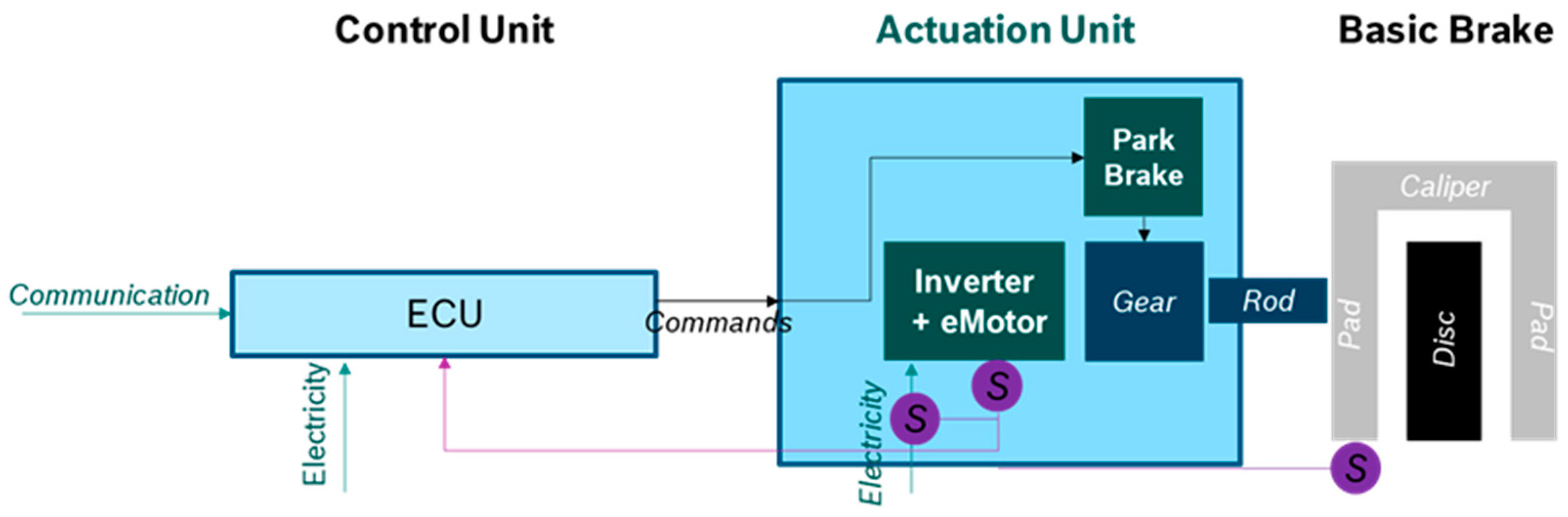
3. Electro-Mechanical Brake Actuators
3.1. Components of EMB Actuators
3.1.1. Sensors
- Brake force or pressure;
- Wheel speed;
- Rotational angle of motor (of EMB).
3.1.2. Control Unit
3.2. Redundancy Concepts for EMB Actuators
3.2.1. Redundant Single Entity
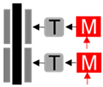
3.2.2. Independent Pads
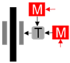
3.2.3. Addition Gear
3.2.4. Parking Brake for Integrity
3.3. Thermal Safety
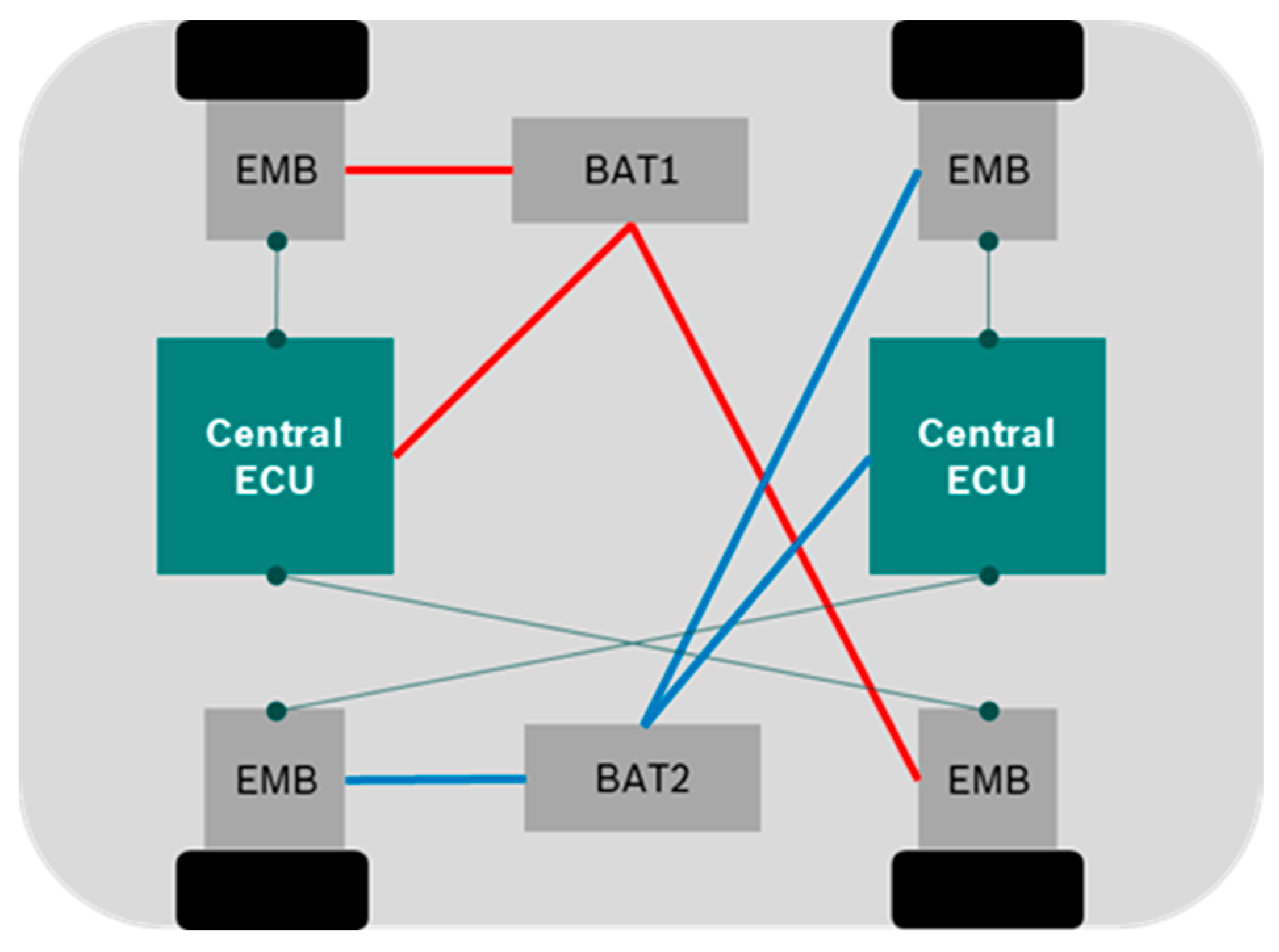
4. EMB Systems
 ).
).4.1. Power Supply
4.1.1. Reliable Power Supply
4.1.2. Power Supply in the EMB Context
4.2. Communication
4.2.1. Ethernet as the Future
4.2.2. Topologies
4.3. Control
4.3.1. Integration Concepts
- Resource management (e.g., CPU, memory, disc drives);
- Service execution and provision for application software;
- Timing.
4.3.2. Fault-Tolerant Control Strategies
4.4. Embedding EMB Actuators into the System
5. Summary and Outlook
6. Patents
Author Contributions
Funding
Informed Consent Statement
Conflicts of Interest
Abbreviation
| AFDX | Avionics Full-Duplex Switched Ethernet |
| ESC | Electronic Stability Program |
| AIS | Abbreviated Injury Scale |
| ICE | Internal Combustion Engine |
| ASIL | Automotive Safety and Integrity Level |
| IMA | Integrated Modular Avionics |
| ASS | Anti-Skid System |
| IPO | Input–Process–Output |
| BBW | Brake-by-Wire |
| OEM | Original Equipment Manufacture |
| CPU | Central Processing Unit |
| RTOS | Real-Time Operating System |
| E/E | Electric and Electronic |
| UNECE | United Nations Economic Commission for Europe |
| EMB | Electromechanical Brake |
References
- Unknown. Autopilot Review. 2021. Available online: https://www.autopilotreview.com/2020-mercedes-benz-s-class-to-offer-eyes-off-level-3-autonomous-driving/ (accessed on 31 December 2021).
- Auguste, A. Hitachi ASTEMO. In Autonomous Driving and Safety Requirements for Braking Systems for Different Automation Levels; China Automotive Steering & Braking Summit 2021: Shanghai, China, 2021. [Google Scholar]
- Diehl, P. Elektromechanische Bremse: Schraubzwinge. Auto Service Praxis, Internet. 2015. Available online: https://www.autoservicepraxis.de/naachrichten/autotechnik/elektromechanische-betriebsbremse-schraubzwinge-2520511 (accessed on 31 December 2021).
- Xiang, W.; Richardson, P.C.; Zhao, C.; Mohammad, S. Utomobile Brake-by-Wire Control System Design and Analysis. IEEE Trans. Veh. Technol. 2008, 57, 138–145. [Google Scholar] [CrossRef]
- Sababha, B.H.; Alqudah, Y.A. A Reconfiguration-Based Fault-Tolerant Anti-Lock Brake-by-Wire System. ACM Trans. Embed. Comput. Syst. 2018, 17, 1–13. [Google Scholar] [CrossRef]
- Schriek, J. Challenge of Change—Reliability and Safety of Innovative E/E-Systems for X-by-wire Features. In SAE Technical Paper Series; SAE World Congress & Exhibition: Detroit, MI, USA, 2004. [Google Scholar]
- Lee, K.J.; Ki, Y.H.; Cheon, J.S.; Hwang, G.; Ahn, H.S. Approach to functional safety-compliant ECU design for electro-mechanical brake systems. Int. J. Automot. Technol. 2014, 15, 325–332. [Google Scholar] [CrossRef]
- Cheon, J.S. Brake By Wire System Configuration and Functions using Front EWB (Electric Wedge Brake) and Rear EMB (Electro-Mechanical Brake) Actuators. In SAE Technical Paper Series; SAE World Congress & Exhibition: Detroit, MI, USA, 2010. [Google Scholar]
- Cheon, J.S.; Kim, J.; Jeon, J.; Lee, S.M. Brake By Wire Functional Safety Concept Design for ISO/DIS 26262. In SAE Technical Paper Series; SAE World Congress & Exhibition: Detroit, MI, USA, 2011. [Google Scholar]
- Möller, D.P.F.; Haas, R.E. Automotive E/E and Automotive Software Technology. In Guide to Automotive Connectivity and Cybersecurity; Springer International Publishing: Cham, Switzerland, 2019; pp. 83–169. [Google Scholar]
- Johansson, L.-Å.; Lindahl, M.; Sivencrona, H.; Törngren, M. ODEEP—Open Dependable Electrical and Electronics Platform—Concept and Projects. In SAE Technical Paper Series; SAE World Congress & Exhibition: Detroit, MI, USA, 2005. [Google Scholar]
- Rieth, P.E.; Raste, T. Future Integration Concepts for ADAS. In Handbook of Driver Assistance Systems; Springer International Publishing: Cham, Switzerland, 2015; pp. 1399–1411. [Google Scholar]
- Bello, L.L. The case for ethernet in automotive communications. ACM SIGBED Rev. 2011, 8, 7–15. [Google Scholar] [CrossRef]
- Chakraborty, S.; Lukasiewycz, M.; Buckl, C.; Fahmy, S.; Chang, N.; Park, S.; Kim, Y.; Leteinturier, P.; Adlkofer, H. Embedded systems and software challenges in electric vehicles. In Proceedings of the 2012 Design, Automation & Test in Europe Conference & Exhibition (DATE), Dresden, Germany, 12–16 March 2012. [Google Scholar]
- Kords, M. statista.com. Statista GmbH. 2021. Available online: https://de.statista.com/statistik/daten/studie/734067/umfrage/anzahl-verkaufter-automobile-nach-laendern-weltweit/ (accessed on 1 January 2022).
- European Union. Regulation No 13-H of the Economic Commission for Europe of the United Nations (UN/ECE)—Uniform Provisions Concerning the Approval of Passenger Cars with Regard to Braking [2015/2364]; European Union: Brussels, Belgium, 2015. [Google Scholar]
- U.S. Department of Transportation. Laboratory Test Procedure For FMVSS 135 Light Vehicle Brake Systems; U.S. Department of Transportation: Washington, DC, USA, 2005.
- General Administration of Quality Supervision, Inspection and Quarantine of People’s Republic of China. Technical Requirements and Testing Methods for Commercial Vehicle and Trailer Braking Systems GB 12676-2014; General Administration of Quality Supervision, Inspection and Quarantine of People’s Republic of China: Beijing, China, 2014. [Google Scholar]
- Bureau of Indian Standards. Automotive Vehicles—Brakes and Braking Systems: Part 2 General Functions and Features; Bureau of Indian Standards: New Delhi, India, 2004. [Google Scholar]
- Bureau of Indian Standards. Automotive Vehicles—Brakes and Braking Systems: Part 9 Requirements for Vehicles equipped with Anti-Lock Braking Systems; Bureau of Indian Standards: New Delhi, India, 2003. [Google Scholar]
- Transport Canada. Technical Standards Document No. 105, Revision 5—Hydraulic and Electric Brake Systems; Transport Canada: Ottowa, ON, Canada, 2015. [Google Scholar]
- UN ECE. United Nations Economic Commission for Europe. Available online: https://unece.org/mission (accessed on 1 January 2022).
- International Standard Organisation. ISO 26262-3: Road Vehicles—Functional Safety—Part 3: Concept Phase; International Standard Organisation: Geneva, Switzerland, 2018. [Google Scholar]
- Verband der Automobilindustrie. VDA 702: Situationskatalog E-Parameter nach ISO 26262-3; Dokumentation Kraftfahrwesen: Berlin, Germany, 2015. [Google Scholar]
- International Standard Organisation. ISO 26262-5: Road Vehicles—Functional Safety—Part 5: Product Development at the Hardware Level; International Standard Organisation: Geneva, Switzerland, 2018. [Google Scholar]
- International Standard Organisation. ISO 26262-8: Road Vehicles—Functional Safety—Part 8: Supporting Processes; International Standard Organisation: Geneva, Switzerland, 2018. [Google Scholar]
- International Standard Organisation. ISO 26262-9: Road Vehicles—Functional Safety—Part 9: Automotive Safety Integritey Level (ASIL)-Oriented and Safety-Oriented Analyses; International Standard Organisation: Geneva, Switzerland, 2018. [Google Scholar]
- Ward, D.D.; Crozier, S.E. The uses and abuses of ASIL decomposition in ISO 26262. In Proceedings of the 7th IET International Conference on System Safety, incorporating the Cyber Security Conference 2012, Edinburgh, UK, 15–18 October 2012. [Google Scholar]
- Sinha, P. Architectural design and reliability analysis of a fail-operational brake-by-wire system from ISO 26262 perspectives. Reliab. Eng. Syst. Saf. 2011, 96, 1349–1359. [Google Scholar] [CrossRef]
- Parker, D.; Godof, A.; Papadopoulos, Y.; Saintis, L. A Study of Automatic Allocation of Automotive Safety Requirements in Two Modes: Components and Failure Modes. In SAE Technical Paper Series; SAE World Congress & Exhibition: Detroit, MI, USA, 2018. [Google Scholar]
- MPutz, H.; Seifert, H.; Zach, M.; Peternel, J. Functional Safety (ASIL-D) for an Electro Mechanical Brake. In SAE Technical Paper Series; SAE World Congress & Exhibition: Detroit, MI, USA, 2016. [Google Scholar]
- Liu, H.; Deng, W.; He, R.; Wu, J.; Zhu, B. Fault-Tolerant Control of Brake-by-Wire Systems Based on Control Allocation. In SAE Technical Paper Series; SAE World Congress & Exhibition: Detroit, MI, USA, 2016. [Google Scholar]
- Kapur, K.C.; Pecht, M. Reliability Engineering; John Wiley & Sons: Hoboken, NJ, USA, 2014. [Google Scholar]
- Department of Defence, USA. MIL-HDBK-338B, Military Handbook—Electronic Reliability Design Handbook; Department of Defence, USA: Fort Belvoir, VA, USA, 1998. [Google Scholar]
- Muenchhof, M.; Beck, M.; Isermann, R. Fault Diagnosis and Fault Tolerance of Drive Systems: Status and Research. Eur. J. Control. 2009, 15, 370–388. [Google Scholar] [CrossRef]
- Zabler, E.; Finkbeiner, S.; Welsch, W.; Kittel, H.; Bauer, C.; Noetzel, G.; Emmerich, H.; Hopf, G.; Konzelmann, U.; Wahl, T.; et al. Automotive Sensors. In Bosch Automotive Electrics and Automotive Electronics; Springer Fachmedien Wiesbaden: Wiesbaden, Germany, 2014; pp. 208–231. [Google Scholar]
- Zabler, E.; Finkbeiner, S.; Welsch, W.; Kittel, H.; Bauer, C.; Noetzel, G.; Emmerich, H.; Hopf, G.; Konzelmann, U.; Wahl, T.; et al. Sensor Measuring Principles. In Bosch Automotive Electrics and Automotive Electronics; Springer Fachmedien Wiesbaden: Wiesbaden, Germany, 2014; pp. 232–309. [Google Scholar]
- Zabler, E.; Finkbeiner, S.; Welsch, W.; Kittel, H.; Bauer, C.; Noetzel, G.; Emmerich, H.; Hopf, G.; Konzelmann, U.; Wahl, T.; et al. Sensor Types. In Bosch Automotive Electrics and Automotive Electronic; Springer Fachmedien Wiesbaden: Wiesbaden, Germany, 2014; pp. 310–353. [Google Scholar]
- Putz, M.H.; Seifert, H.; Zach, M.; Schiffer, M.; Peternel, J. Accuracy of Sensor-Less Control of an Electro-Mechanical Brake. In SAE Technical Paper Series; SAE World Congress & Exhibition: Detroit, MI, USA, 2015. [Google Scholar]
- Schwarz, R.; Isermann, R.; Böhm, J.; Nell, J.; Rieth, P. Clamping Force Estimation for a Brake-by-Wire Actuator. In SAE Technical Paper Series; SAE World Congress & Exhibition: Detroit, MI, USA, 1999. [Google Scholar]
- Ki, Y.-H.; Ahn, H.-S.; Cheon, J.S. Fault-Tolerant Control of EMB Systems. SAE Int. J. Passeng. Cars Electron. Electr. Syst. 2012, 5, 579–589. [Google Scholar] [CrossRef]
- Hoseinnezhad, R.; Saric, S.; Bab-Hadiashar, A. Estimation of Clamp Force in Brake-by-Wire Systems: A Step-by-Step Identification Approach. In SAE Technical Paper Series; SAE World Congress & Exhibition: Detroit, MI, USA, 2006. [Google Scholar]
- Schmidt, P.B.; Gasperi, M.L.; Ray, G.; Wijenayake, A.H. Initial rotor angle detection of a nonsalient pole permanent magnet synchronous machine. In Proceedings of the IAS’97. Conference Record of the 1997 IEEE Industry Applications Conference Thirty-Second IAS Annual Meeting, New Orleans, LA, USA, 5–9 October 1997. [Google Scholar]
- Hwang, W.; Han, K.; Huh, K. Fault detection and diagnosis of the electromechanical brake based on observer and parity space. Int. J. Automot. Technol. 2012, 13, 845–851. [Google Scholar] [CrossRef]
- Kaiser, M.; Aue, A. Steuergerät. In Kraftfahrtechnisches Taschenbuch; Springer Fachmedien: Wiesbaden, Germany, 2019; pp. 1420–1429. [Google Scholar]
- Isermann, R. Fehlertolerante mechatronische Systeme, Teil 1 (Fault-tolerant Mechatronic Systems, Part 1). at-Autom. 2007, 55, 170–179. [Google Scholar]
- U.S. Department of Defence. MIL-HDBK-217F: Reliablity Prediction of Electronic Equipment; U.S. Department of Defence: Washington, DC, USA, 1991.
- Weiberle, R. Elektrisches Bremssystem, Insbesondere Elektromechanisches Bremssystem. Germany Patent DE102009046238B4, 4 November 2021. [Google Scholar]
- Bei, S.; Zhang, L.; Lai, X.; Wang, Z.; Tong, X.; Bian, J.; Ma, Z.; Wang, K. Self Power Supply Type Double-Motor Brake Execution Mechanism of Automobile Electro-Mechanical Brake System. China Patent CN106347339A, 25 January 2017. [Google Scholar]
- Takahashi, H.; Takahashi, K. Electric Brake. U.S. Patent US7806241B2, 5 October 2010. [Google Scholar]
- Fu, Y.; Qin, C.; Liu, Q.; Gao, Q.; Shu, X. Electromechanical Brake Device and Vehicle with Same. China Patent CN211202695U, 7 August 2020. [Google Scholar]
- Nuesse, D. Elektromechanische Bremsvorrichtung für ein Fahrzeug. Germany Patent DE102018218472A1, 3 April 2020. [Google Scholar]
- Gohbrandt, J.; Stroschein, J. Verfahren zum Erkennen von Schäden an Mechanischen Bauteilen einer Elektromechanischen Bremse, Elektronisch Gesteuertes Bremssystem, Computerprogrammprodukt, Steuergerät und Kraftfahrzeug. Germany Patent DE102019128742A1, 29 April 2021. [Google Scholar]
- Martin, S. Elektromechanische Bremse zum Abbremsen einer Sich Drehenden Komponente und Bremsanlage mit Einer Elektromechanischen Bremse. Germany Patent DE10319082 B3, 16 December 2004. [Google Scholar]
- Schumann, F. Elektromechanische Bremsvorrichtung. Germany Patent WO9736116A1, 2 October 1997. [Google Scholar]
- Kim, S. Disk Break Apparatus For Electromechanical Brake System. U.S. Patent US2009223752A1, 10 September 2009. [Google Scholar]
- Hartmann, H.; Schautt, M. Fail-Safe Concept for an Electromechanical Brake. U.S. Patent US7748793B2, 26 November 2004. [Google Scholar]
- Sim, G.; Jian, J. Electro-Mechanical Brake System and Method for Operating Same. Korea Patent WO2021158022A1, 12 August 2021. [Google Scholar]
- Saitner, M.; Keller, R. Elektrisch betreibbare Parksperrenvorrichtung für ein Fahrzeuggetriebe. Germany Patent DE102009028858A1, 3 March 2011. [Google Scholar]
- Schade, K.; Linhoff, P. Elektromechanische Bremse und zugehöriges Betriebsverfahren. Germany Patent DE102011076424A1, 29 November 2012. [Google Scholar]
- Keski-Luopa, M. Sähkömekaaninen Seisontajarrujärjestely. Finland Patent FI119855B, 6 July 2007. [Google Scholar]
- Yang, L.; Liu, S.; Ma, F.; Miao, F. Electromechanical Brake Cylinder with Parking Function and Brake System. China Patent CN111319596 A, 23 June 2020. [Google Scholar]
- Laxhuber, T.; Baumgartner, H.; Pahle, W. Device and Method for Monitoring a Brake-Applying Electromechanical Device for Vehicle Brakes. U.S. Patent US6774595B1, 10 August 2004. [Google Scholar]
- Friesen, U. Electromechanical Brake Applying Device. U.S. Patent US2005006948A1, 13 January 2005. [Google Scholar]
- Schaffer, W. Electromechanical Wheel Brake System. U.S. Patent US6340077 BA, 27 May 1999. [Google Scholar]
- The Engineering Toolbox. NEMA Insulation Classes. 2004. Available online: https://www.engineeringtoolbox.com/nema-insulation-classes-d_734.html. (accessed on 21 July 2022).
- Belhocine, A.; Bouchetara, M. Thermal–Mechanical Coupled Analysis of a Brake Disk Rotor. ASM Int. 2013, 49, 167–176. [Google Scholar]
- Najmi, H.; Kumar, N.; Singh, A.; Singh, R.; Kumar, S. Thermal analysis of brake disc of an automobile. In Proceedings of the International Conference on Futuristic and Sustainable Aspects in Engineering and Technology (FSAET 2020), Mathura, India, 18–19 December 2020; IOP Conference Series: Materials Science and Engineering. Volume 1116, pp. 1–14. [Google Scholar]
- Jian, Q.; Wang, L.; Shui, Y. Thermal analysis of ventilated brake disc based on heat transfer. Int. J. Therm. Sci. 2020, 155, 106356. [Google Scholar] [CrossRef]
- Hwang, K.Y.; Song, B.K.; Kwon, B.I.K. Asymmetric dual winding three-phase PMSMfor fault tolerance of overheat in electricbraking system of autonomous vehicle. IET Electr. Power Appl. 2019, 13, 1891–1898. [Google Scholar] [CrossRef]
- Fassnacht, J. Bordnetze für Hybrid- und Elektrofahrzeuge. In Kraftfahrtechnisches Taschenbuch; Springer Fachmedien: Wiesbaden, Germany, 2019; pp. 1304–1309. [Google Scholar]
- Bergmiller, P. Design and Safety Analysis of a Drive-by-Wire Vehicle. In Automotive Systems Engineering; Springer: Berlin/Heidelberg, Germany, 2013; pp. 147–202. [Google Scholar]
- Kelling, N.A.; Heck, W. The BRAKE Project—Centralized Versus Distributed Redundancy for Brake-by-Wire Systems. In SAE Technical Paper Series; SAE World Congress & Exhibition: Detroit, MI, USA, 2002. [Google Scholar]
- Koehler, A.; Bertsche, B. An Approach of Fail Operational Power Supply for Next Generation Vehicle Powernet Architectures. In Proceedings of the 30th European Safety and Reliability Conference and 15th Probabilistic Safety Assessment and Management Conference (ESREL2020-PSAM15), Venice, Italy, 1–5 November 2020. [Google Scholar]
- Ross, H.-L. System Engineering for Development of Requirements and Architecture. In Functional Safety for Road Vehicles; Springer International Publishing: Cham, Switzerland, 2016; pp. 75–199. [Google Scholar]
- Gebert, J.; Bauer, F.; Chamas, M.; Meseth, M.; Michel, H.-U.; Singh, G.; Traub, M. HiBord: Hochverfügbare und Intelligente Bordnetztopologien für Automatisierte Fahrzeuge; BMW AG: Munich, Germany, 2020. [Google Scholar]
- Kilian, P.; Kohler, A.; Bergen, P.V.; Gebauer, C.; Pfeufer, B.; Koller, O.; Bertsche, B. Principle Guidelines for Safe Power Supply Systems Development. IEEE Access 2021, 9, 107751–107766. [Google Scholar] [CrossRef]
- Nilsson, A.; Linidqvist, A. An Electromechanical Brake System. China Patent WO2021122214A1, 24 June 2021. [Google Scholar]
- Niedermeier, E. Brake system for a motor vehicle. U.S. Patent US6189981B1, 20 February 2001. [Google Scholar]
- Stoelzl, S.; Giers, B.; Oehler, R.; Willimowski, P.; Boehm, J.; Nell, J.; Hoffmann, O. Electromechanical Brake System. U.S. Patent US6317675B1, 1 September 2000. [Google Scholar]
- Yan, L.; Hao, Z.; Sui, Q. EMB Redundancy Control System and Method. China Patent CN113110238A, 13 July 2021. [Google Scholar]
- Weiberle, R. Elektrisches Bremssystem, Insbesondere Elektromechanisches Bremssystem. Germany Patent DE102009046231A1, 5 May 2011. [Google Scholar]
- Doericht, M.; Schmid, R. Elektromechanische Kraftfahrzeug-Bremsvorrichtung. Germany Patent WO0037818A1, 29 June 2000. [Google Scholar]
- Weiberle, R.; Mueller, B.; Hassdenteufel, F. Electric Brake System i.e., Electromechanical Brake System, for Motor Vehicle, Has Brake Circuits Provided with Control Apparatuses, and Rolling Dynamics Control Unit Integrated in Each Control Apparatus. France Patent FR2952011A1, 6 May 2011. [Google Scholar]
- Winkler, J. Bordnetz für ein Fahrzeug und Verfahren zur Energieversorgung eines Sicherheitsrelevanten Verbrauchers eines Bordnetzes. Germany Patent DE102006010713B4, 1 April 2010. [Google Scholar]
- Holzwarth, J.; Krausen, L. System zur Aktorsteuerung, Insbesondere Bremssystem. Germany Patent DE102006053617A1, 15 May 2008. [Google Scholar]
- Liu, Q.; Qin, C.; Fu, Y.L.D.; Liao, K. Vehicle Electromechanical Brake System and Vehicle with Same. China Patent CN112550189A, 26 March 2021. [Google Scholar]
- Gehring, O.; Heilmann, H.; Schwarzhaupt, A.; Spiegelberg, G.; Sulzmann, A. Verfahren und Anordnung zur Regelung einer Bremsanordnung mit redundantem Energiepfad zur Energieversorgung der Regelungseinrichtung. Germany Patent DE102004014623A1, 13 October 2005. [Google Scholar]
- Basic Principles of Networking. In Bosch Automotive Electrics and Automotive Electronics; Springer Fachmedien Wiesbaden: Wiesbaden, Germany, 2014; pp. 70–81.
- Weiler, H.; Lorenz, W.; Prelle, O.; Thoss, D. Vernetzung im Kfz, Busse im Kfz. In Kraftfahrtechnisches Taschenbuch; Springer Fachmedien: Wiesbaden, Germany, 2019; pp. 1450–1458. [Google Scholar]
- Zhu, H.; Zhou, W.; Li, Z.; Li, L.; Huang, T. Requirements-Driven Automotive Electrical/Electronic Architecture: A Survey and Prospective Trends. IEEE Access 2021, 9, 100096–100112. [Google Scholar] [CrossRef]
- Haas, W.; Langjahr, P. Cross-domain vehicle control units in modern E/E architectures. In Internationales Stuttgarter Symposium; Springer Fachmedien Wiesbaden: Wiesbaden, Germany, 2016; pp. 1619–1627. [Google Scholar]
- Abendroth, S. Automotive Ethernet as enabler for flexible EE architectures. In Proceedings of the 4th International Conference Advanced Chassis and Safety Architecture, Stuttgart, Germany, 13 May 2013. [Google Scholar]
- Hager, M.; Gromala, P.; Wunderle, B.; Rzepka, S. Affordable and Safe High Performance Vehicle Computers with Ultra-Fast On-Board Ethernet for Automated Driving. In Advanced Microsystems for Automotive Applications 2018; Springer International Publishing: Cham, Switzerland, 2018; pp. 56–68. [Google Scholar]
- Sommer, S.; Camek, A.; Becker, K.; Buckl, C.; Zirkler, A.; Fiege, L.; Armbruster, M.; Spiegelberg, G.; Knoll, A. RACE: A Centralized Platform Computer Based Architecture for Automotive Applications. In Proceedings of the 2013 IEEE International Electric Vehicle Conference (IEVC), Santa Clara, CA, USA, 23–25 October 2013. [Google Scholar]
- Ross, H.-L. System Safety Engineering. In Safety for Future Transport and Mobility; Springer International Publishing: Cham, Switzerland, 2020; pp. 159–265. [Google Scholar]
- Schmidt, D. The Airbus A380—Towards a New Futre for Air Transport; Airbus: Samara, Russia, 2007. [Google Scholar]
- Autosar. Autosar. 2022. Available online: https://www.autosar.org/standards/classic-platform/ (accessed on 1 January 2022).
- Isermann, R.; Schwarz, R.; Stölzl, S. Fault-tolerant drive-by-wire systems. IEEE Control Syst. 2002, 22, 64–81. [Google Scholar]
- Ross, H.-L. Automated Driving and Control. In Safety for Future Transport and Mobility; Springer International Publishing: Cham, Switzerland, 2020; pp. 307–390. [Google Scholar]
- Nillson, A.; Lindqvist, A.; Dong, X. A Brake System For a Vehicle. China Patent WO2021139954A1, 15 June 2021. [Google Scholar]
- Kim, J.G. Brake System For Vehicle. U.S. Patent US2010007199A1, 14 January 2010. [Google Scholar]
- Huang, S.; Zhou, C.; Yang, L.; Qin, Y.; Huang, X.; Hu, B. Transient fault tolerant control for vehicle brake-by-wire systems. Reliab. Eng. Syst. Saf. 2016, 149, 148–163. [Google Scholar] [CrossRef]
- Weiberle, R.; Mueller, B.; Kriso, S. Electrical Brake System i.e., Electromechanical Brake System, for Motor Vehicle, Has Brake System Controlling CPU Transmitting Signal by Communication System of Brake Circuit, and Seizing Unit Directly Connected to Controller. France Patent FR2952886A1, 27 May 2011. [Google Scholar]
- Holzwarth, J. Electromechanical Brake System with a Failsafe Energy Supply and Method for Failsafe Energy Supply in an Electromechanical Brake System For Vehicles. U.S. Patent US2010243388A1, 30 September 2010. [Google Scholar]
- Choi, H.R.; Hyun, D.Y. Electromechanical Brake System having Suspension Control Function. U.S. Patent US2021108692A1, 15 April 2021. [Google Scholar]
- Fijalkowski, B.T. Anti-Lock EFMB or EPMB BBW AWB Dispulsion Mechatronic Control Systems. In Automotive Mechatronics: Operational and Practical Issues; Springer: Dordrecht, The Netherlands, 2010; pp. 463–495. [Google Scholar]
- Molfetta, D.; Ringlstetter, M.; Zelger, C. Redundante Übermittlung von Bremsanweisungen. Germany Patent DE102007001371A1, 10 July 2008. [Google Scholar]


| ID | Requirement | EU + UK | USA | China | India | Canada |
|---|---|---|---|---|---|---|
| D.01 | Two independent energy reserves | 5.2.2 5.2.4 | - | 4.2.2 | 4.2.1 | - |
| D.02 | Two independent energy transmissions | 5.2.2 5.2.4 | - | 4.2.2 | 4.2.1 | - |
| D.03 | Each energy reserve must be connected to two or more wheels | 5.2.2 | - | 4.2.2 | 4.2.1 | - |
| D.04 | Each energy transmission must be connected to two or more wheels | 5.2.2 | - | 4.2.2 | 4.2.1 | - |
| D.05 | All 4 wheels shall be actuated by brakes | 5.2.6 | 14.24 | 4.2.7 | 4.2.1 | 5.1 |
| D.06 | Regenerative braking is allowed to be applied alone | 5.2.7 | - | - | - | - |
| D.08 | ESC (Electronic Stability Program) shall apply braking torque to the wheels individually | UN ECE R140 | FMVSS 126 | - | - | TSD 126 |
| D.09 | Brake shall return to OFF position when released | 5.2.2 | - | - | - | - |
| ID | Requirement | EU + UK | USA | China | India | Canada |
|---|---|---|---|---|---|---|
| P.01 | Provide more than 6.43 m/s² deceleration with the engine disconnected | A3.2 | 14.7 | 5.2.1 | 4.1.1 | 5.1.1 |
| P.02 | Provide more than 5.67 m/s² deceleration with the engine connected | A3.2 | 14.8 | 5.2.1 | 4.1.1 | 5.1.1 |
| P.03 | Energy reserve must be dimensioned to halt vehicle 10 times from 100 km/h | 5.2.4 5.2.20 | 14.18 | - | 4.2.1 | 5.1.2.2 |
| P.04 | Energy supply must be dimensioned to halt vehicle according to P.11 | 5.2.4 | - | 4.2.5 4.2.14 | 4.2.1 | - |
| P.05 | Transmission delay must be less than 0.6 s | A3.3 | - | 5.4.1 | 4.3.1 | - |
| ID | Failure | Requirement | EU + UK | USA | China | India | Canada |
|---|---|---|---|---|---|---|---|
| P.11 | 1st Circuit | Provide more than 2.6 m/s² deceleration | A3.2 | 14.14 | 5.2.1 | 4.1.2 | 5.1.2.1 |
| P.12 | ASS | Provide more than 5.15 m/s² deceleration | A6.4 | 14.12 | - | 9.5.4 | 5.5.2 |
| P.13 | Brake Distr. | Provide more than 3.86 m/s² deceleration with the engine disconnected | A5.4 | 14.13 14.17 | A6 | - | - |
| P.14 | Power Brake Unit | Performance of P.11 | - | 14.18 | - | - | 5.1.3.1 |
| P.15 | Booster | Performance of P.11 | - | 14.21 | 5.2.3 | - | 5.1.3.1 |
| P.16 | Any 1st E/E | Performance of P.01 must still be available | - | - | - | - | 5.1.3.5 |
| ID | Failure | Requirement | EU + UK | USA | China | India | Canada |
|---|---|---|---|---|---|---|---|
| D.11 | any | No unintended application | 5.2.9 | - | - | - | - |
| D.12 | E-Supply | E-reserves must tolerate it | 5.2.15 | - | - | - | - |
| D.13 | Transmission | No unintended application of parking brake | 5.2.19 | - | - | - | - |
| D.14 | Any 1st | Application still possible | 5.2.20 | - | - | - | - |
| P.15 | Booster | Performance of P.11 | - | 14.21 | 5.2.3 | - | 5.1.3.5 |
| Malfunction | Range [m/s2 or °] | ASIL | |||||
|---|---|---|---|---|---|---|---|
| from | to | D | C | B | A | ||
| Alarm to Drive | Degradation of deceleration | 10 | 6.5 | [2] | |||
| Degradation of deceleration | 6.5 | 2.44 | [30] | [2] | |||
| Degradation of deceleration | 2.44 | 0 | [2,9,29,30] | [9] | [9] | ||
| Unintended activation | 0 | 2.44 | [31] | ||||
| Unintended activation | 2.44 | 6.5 | [31] | [2] | |||
| Unintended activation | 6.5 | 10 | [31] | [2] | |||
| No Alarm | Degradation of deceleration | 10 | 6.5 | [2] | |||
| Degradation of deceleration | 6.5 | 2.44 | [2,30] | ||||
| Degradation of deceleration | 2.44 | 0 | [2,9,29,30] | [9] | [9] | ||
| Unintended yaw | 15 | 180 | [2] | ||||
| Unintended yaw | 0 | 15 | [2] | ||||
| Incorrect brake torque | - | - | [30] | ||||
| Unintended activation of actuator | - | - | [31] | ||||
| Passivation of one actuator | - | - | [31] | ||||
 |  |  |  | 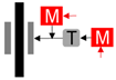 |
| No Redundancy (for Comparison) | Redundant single Entity | Independent Pads | Addition Gear | Parking Brake for Integrity |
| Legend: |  |  | 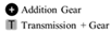 |  |
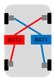 |  | 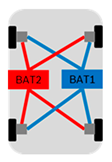 | 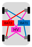 | 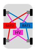 |
| X-Circuits | H Circuit | Full Redundancy | X Circuit + High-Voltage Redundancy | Local Energy Supplies as Backup |
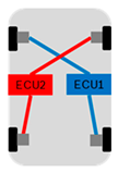 |  | 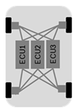 | 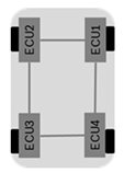 |  |
| X-Circuit | H-Circuit | Triplex-Topology | Quadruplex- Topology | Hybrid Topology |
Publisher’s Note: MDPI stays neutral with regard to jurisdictional claims in published maps and institutional affiliations. |
© 2022 by the authors. Licensee MDPI, Basel, Switzerland. This article is an open access article distributed under the terms and conditions of the Creative Commons Attribution (CC BY) license (https://creativecommons.org/licenses/by/4.0/).
Share and Cite
Schrade, S.; Nowak, X.; Verhagen, A.; Schramm, D. Short Review of EMB Systems Related to Safety Concepts. Actuators 2022, 11, 214. https://doi.org/10.3390/act11080214
Schrade S, Nowak X, Verhagen A, Schramm D. Short Review of EMB Systems Related to Safety Concepts. Actuators. 2022; 11(8):214. https://doi.org/10.3390/act11080214
Chicago/Turabian StyleSchrade, Simon, Xi Nowak, Armin Verhagen, and Dieter Schramm. 2022. "Short Review of EMB Systems Related to Safety Concepts" Actuators 11, no. 8: 214. https://doi.org/10.3390/act11080214
APA StyleSchrade, S., Nowak, X., Verhagen, A., & Schramm, D. (2022). Short Review of EMB Systems Related to Safety Concepts. Actuators, 11(8), 214. https://doi.org/10.3390/act11080214