1. Introduction
The commercialization of piezoelectric ceramics has developed rapidly in the past 10 years [
1,
2,
3]. Opportunities for its application in the fields of piezoelectric energy harvesting, piezoelectric fuel injection, piezoelectric motors, piezoelectric printing presses, piezoelectric controlled wire guides, micropositioning systems, and so on are also increasing [
4,
5,
6,
7]. For a long time, lead zirconate titanate (Pb(Zr
1−xTi
x)O
3 or PZT) has been the main material of piezoelectric ceramics due to its excellent piezoelectric properties [
8,
9]. However, the production and application of PZT result in a large amount of lead pollution in the form of lead oxide and lead zirconate titanate [
10,
11]. In order to protect the environment, increasing attention is being paid to research of lead-free piezoelectric materials [
12,
13,
14,
15].
In the processing and application of lead-free piezoelectric materials, geometric discontinuities (holes, cuts, notches) may occur. Under complex loads and harsh conditions, stress concentration is likely to occur, resulting in fatigue cracks in the periphery, and even structural failure [
16,
17,
18]. Furthermore, stress concentration around the geometric discontinuity is the basis of subsequent fracture and fatigue analysis, which has important practical significance.
Some scholars have applied different engineering methods to analyze the stress concentration. Smith and Kullgren et al. [
19] obtained the stress intensity factor around the partial elliptical crack caused by the fastener hole on the finite-thick plate by the finite element-alternating method. In addition, Kim et al. [
20] applied finite element analysis to calculate a polynomial expression for the calculation of the stress intensity factor for a lug with a through-thickness crack. Liang et al. [
21] performed a series of numerical simulations on circular piezoelectric plates with holes using a special boundary element method. However, neither FEM nor BEM can obtain the analytical formula of stress factor. These numerical methods cannot reveal a clear relationship between stress concentrations and related factors (material parameters, hole shape parameters, etc.) [
22,
23].
Therefore, more and more researchers are trying to derive analytical solutions using elastic mechanics and complex functions. Wang et al. [
24] used the Stroh-type formula to study the anti-plane problem of equilateral triangle hole cracking in transversely isotropic piezoelectric materials. Fan et al. [
25] studied the inverse plane problem of edge cracks generated by equilateral triangular holes in one-dimensional hexagonal piezoelectric quasicrystals by introducing numerical conformal mapping using the Stroh-type formula. These studies only discuss a single common shape and do not discuss the effect of different shape parameters on stress concentration [
26,
27]. Wang et al. [
28] solved arbitrary holes with edge cracks in transversely isotropic piezoelectric materials using the complex variable method and the numerical conformal mapping method. The loads used in these studies are all static. However, real-world loading conditions are often dynamic and complex.
In this paper, diffraction and dynamic stress concentration near several common-shaped holes of lead-free piezoelectric ceramics under the action of electroelastic coupled-load waves are investigated. First, we reduce the problem to a 2D inverse plane problem by setting the load to be an inverse plane shear wave. Then, the basic form of elastic wave field and electric potential solution is obtained by the wave function expansion method. Affine transformations are used to map common-shaped holes into circular holes to simplify boundary conditions. Then, according to the simplified free boundary conditions, the undetermined coefficients of the diffraction field are determined, and the analytical solution of the dynamic stress concentration factor (DSCF) around the hole is given. Finally, taking (Ba0.85Ca0.15)(Zr0.1Ti0.9)O3 as an example, the DSCF results of common-shaped holes under different parameters are calculated and analyzed, as well as the effects of incident wave number, shape parameters and piezoelectric parameters on stress concentration.
2. Problem and Basic Equations
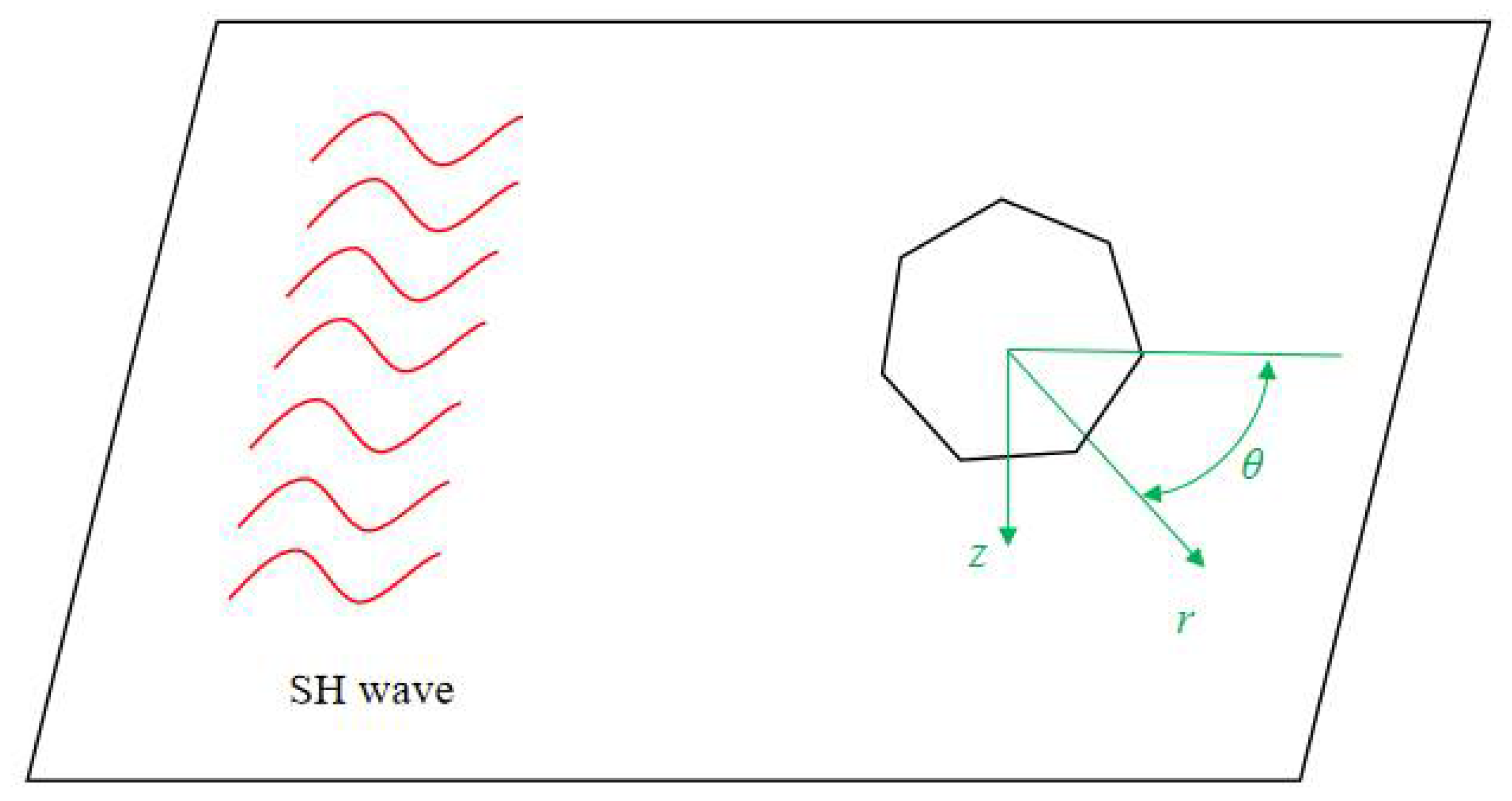
In order to meet the needs of engineering design, it is inevitable to open holes of various shapes on the lead-free piezoelectric ceramics. In addition, some structures may also have holes or cracks during service, and these holes may produce stress concentration or even break under the action of daily dynamic load. We intend to use incident elastic waves to simulate dynamic loads in everyday life. Among them, the dynamic stress concentration caused by the anti-plane shear wave (SH wave) is normally used as the basis for the calculation of the stress field intensity factor of the type iii dynamic fracture. Therefore, the inverse plane shear wave (SH wave) was selected as the incident wave in this paper. According to the characteristics of SH waves, the three-dimensional electroelastic coupling problem can be transformed into a two-dimensional anti-plane problem.
The hole model of arbitrary shape on the lead-free piezoelectric ceramic is shown in
Figure 1. We took the centroid of the shape as the origin and the incident direction of the SH wave as the polar axis to establish a cylindrical coordinate system. Lead-free piezoelectric ceramics are set to be isotropic and uniform.
For the two-dimensional anti-plane problem, the out-of-plane displacement and in-plane electric field are only functions of coordinates
and
, and all physical quantities depend only on the anti-plane displacement
and in-plane electric potential
.
where
and
are used to describe the in-plane displacement.
In the cylindrical coordinate system, the coupling characteristics of mechanical deformation and electric field of lead-free piezoelectric ceramics can be described by the following constitutive equation:
where
is the elastic constant;
is the piezoelectric constant;
is the dielectric constant. In the quasi-static electromagnetic approximation, the stress
and electric displacement
should satisfy the following equilibrium equation:
Substituting Equation (2) into (3) and sorting it, the general equation describing the problem in the cylindrical coordinate system can be obtained as follows:
3. Forms of Solutions for Incident, Scattered and Electroelastic Waves
Since the differential equation to be solved is electroelastic coupling, we used the auxiliary function method for decoupling. Construct the auxiliary function
and substitute it into Equation (4):
where
is the propagation velocity of SH waves,
. The decoupled equations are all classical differential equations, and their solution forms can be obtained. Therefore, we can obtain the displacement field and electric potential field of the scattered wave as follows:
where
and
are the undetermined coefficient used to describe the scattered elastic wave field and scattered potential field, respectively.
is the
n-th order Bessel function of the third kind.
is the incident wave number. The superscript
refers to the scattered wave field.
Since the SH wave is also a classical incident wave, the form of the solution of its displacement field and electric potential field can be described by the following formulas:
The superscript
refers to the incident wave field. The total field and total potential field of elastic waves in lead-free piezoelectric ceramics can be obtained by superimposing the incident field and scattered field:
where the superscript
refers to the total wave field. In the hole, the elastic wave field does not exist, and the electric displacement field is not equal to zero. The form of the electric displacement field in the hole can be expressed as
where
is the undetermined coefficient; similar to
and
, it needs to be determined by boundary conditions. The superscript
refers to the wave field inside the hole.
4. Mapping Function
In order to simplify the boundary of regular polygons, we can introduce complex variables according to the theory of complex functions:
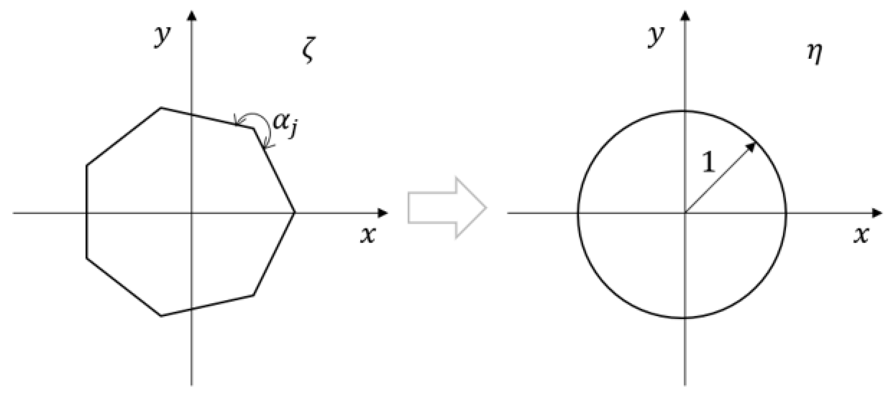
Then, we need to map the polygon boundary to a unit circle using the conformal transformation. A schematic diagram of conformal mapping is shown in
Figure 2.
To map the outer region of the regular
n-sided hole on the
plane to the outer region of the unit circle in the
plane, the mapping function for the SC transformation is given below [
29]:
where the constants
and
are the shape coefficient and position coefficient of the regular
n-sided hole, respectively.
and
can be calculated by selecting two sets of corresponding points. One of the sets of points is selected as the corresponding set of points at infinity on the two planes, resulting in
. Another set of points can be selected as a vertex of a regular polygon and a corresponding point on the circle for subsequent calculation of
.
is the number of sides of a regular
n-gon,
is the vertex corresponding to the regular
n-gon,
is the group angle of the
j-th interior angle divided by
. Then,
Substitute
and
in Equation (11), and integrate them in the range of
and
to obtain the mapping function as follows:
where
5. Boundary Conditions and Determination of Mode Coefficients
The boundary conditions on the
plane can be simplified as
Substitute Equation (12) into Equations (8) and (9):
Substituting Equation (15) into (14), the boundary conditions under the conformal transformation can be obtained:
According to the above derivation, the boundary conditions can be written as an infinite-dimensional system of equations.
where
Using the orthogonality of complex exponential functions, multiply both sides of the equation by
.
where
According to Equation (18), we can derive the infinite system of linear equations for computing the mode coefficients , where .
6. Dynamic Stress-Concentration Factor
The dynamic stress concentration around the hole can be described by the Dynamic Stress-Concentration Factor (DSCF). The DSCF is the ratio of the hoop dynamic stress around the defect to the hoop stress amplitude in the incident direction of the incident wave [
30].
where
and
7. Simulation of Numerical Examples and Discussion
According to the above derivation, we can calculate the DSCF around the regular polygonal hole on any piezoelectric ceramic under the condition of known piezoelectric ceramic-related parameters. However, the resulting DSCF forms are infinite. According to the characteristics of the Bessel function, as n increases, the coefficients () all tend to 0. In the actual calculation, we can choose the appropriate minimum value of n according to the decision to truncate the DSCF. In order to check the correctness and usability of the derivation, we carried out a numerical simulation with a specific material and analyzed the results, which is presented below.
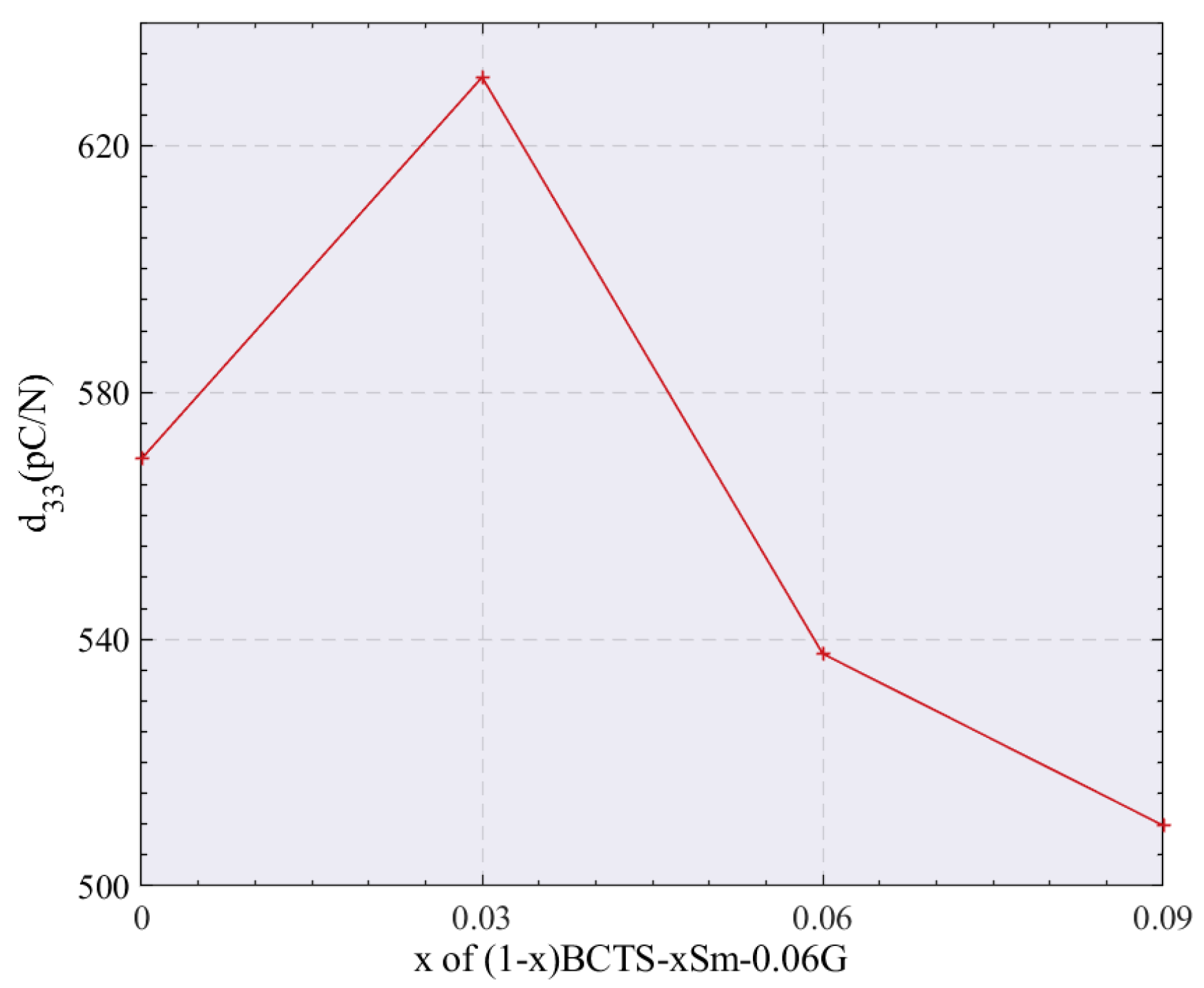
BaTiO3 (BT)-based piezoelectric ceramics are widely regarded as one of the candidates for lead-free piezoelectric ceramics due to their superior piezoelectricity. Wang et al. [
31] studied the BT-based ceramics’ (1 −
x)[(Ba
0.94Ca
0.06) (Ti
0.92Sn
0.08)]-
xSm
2O
3-0.06 mol% GeO
2 (abbreviated as (1 −
x)BCTS-
xSm-0.06G) comprehensive electrical properties. They proposed that the material obtained optimized piezoelectric properties under the condition of 3 kv/mm (non-180° domain switching under high polarization electric field). Therefore, we selected (1 −
x)BCTS-
xSm-0.06G with a different doping ratio (
x) under the condition of 3 kv/mm for numerical simulation, as shown in
Figure 3.
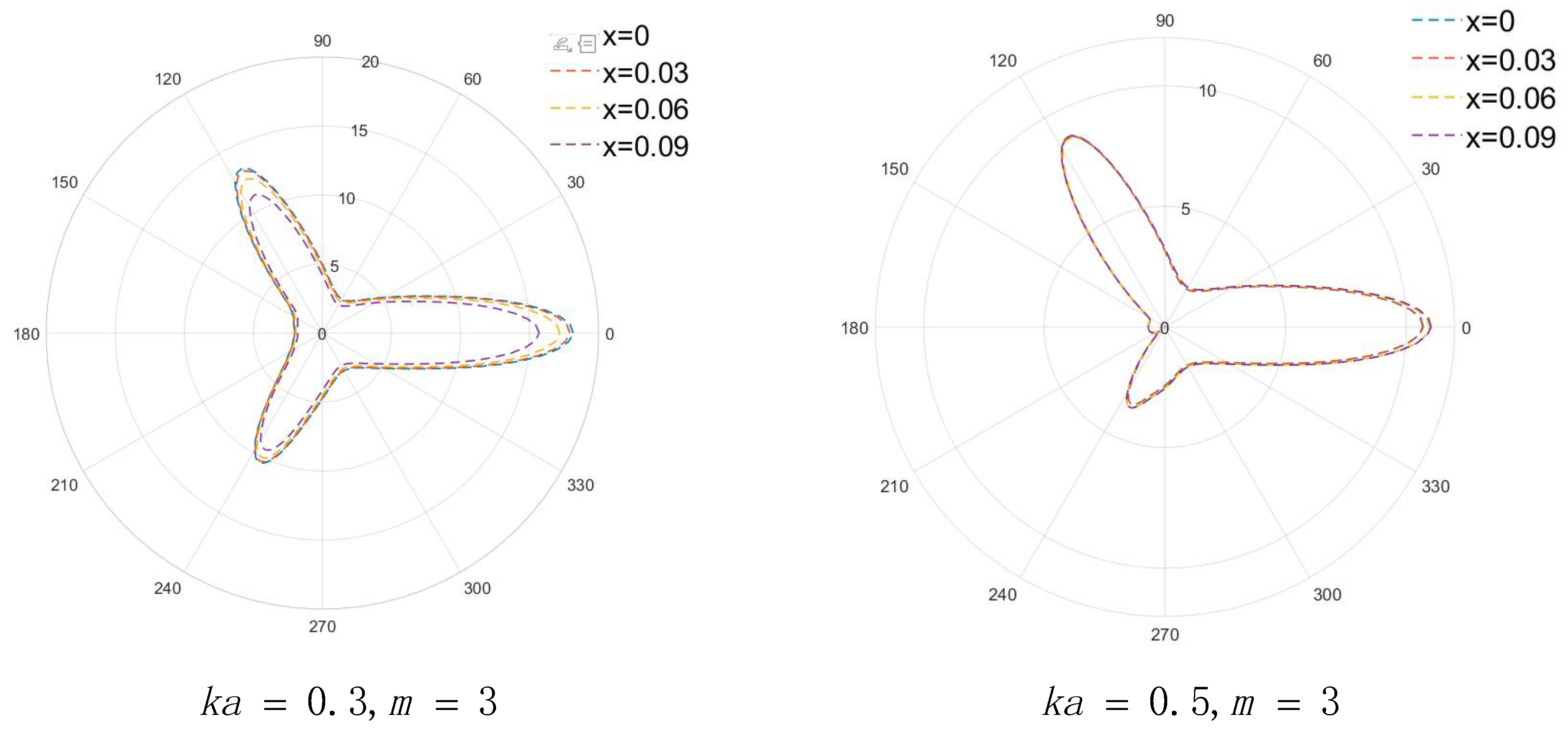
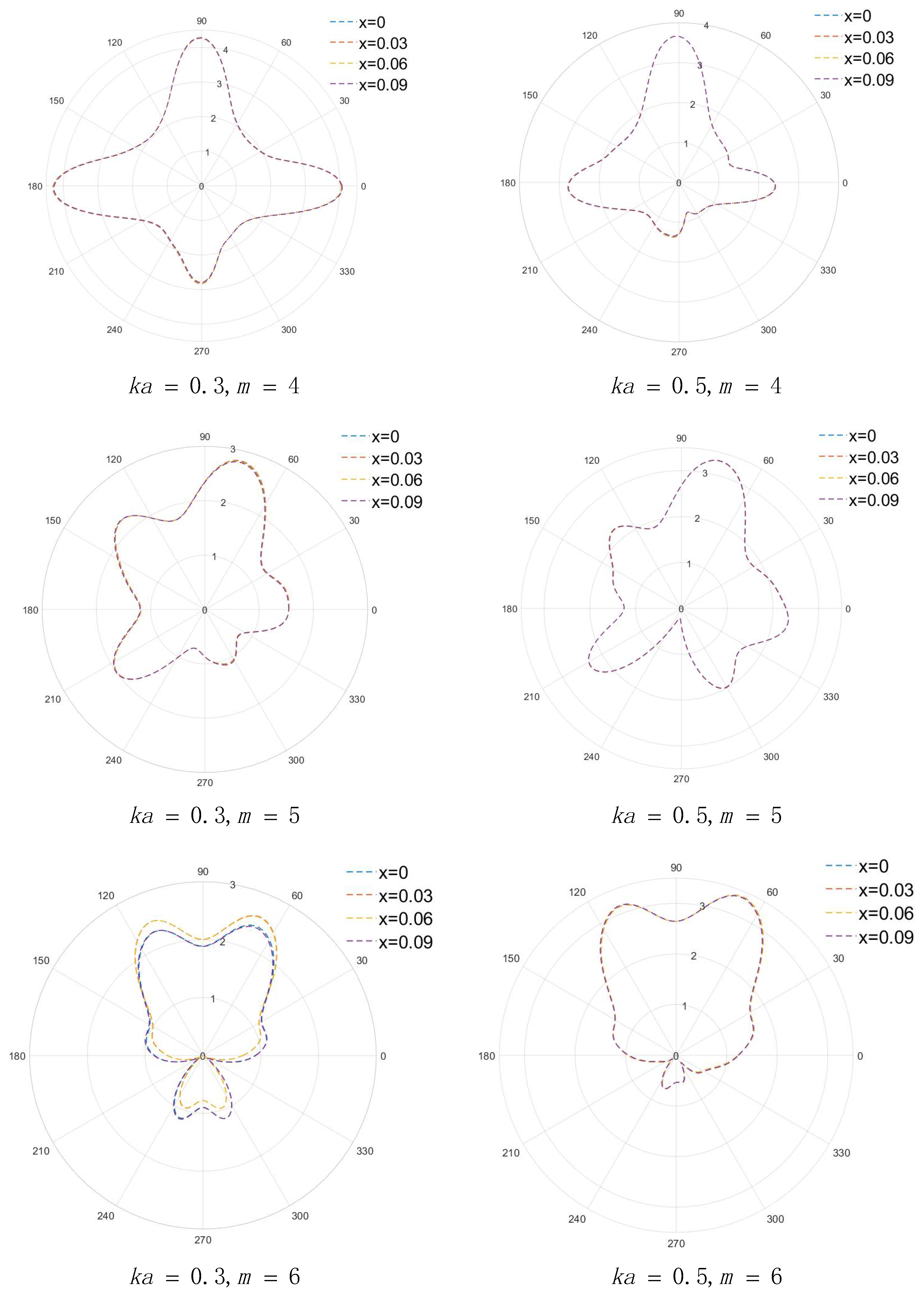
It can be determined from the dynamic stress-concentration formula of Equation (22) that the dynamic stress-concentration coefficient is related to the wave number (
) of the incident elastic wave, the piezoelectric constant (
d33) of the material and the mapping function (Ω(
η)). By changing
ka, we obtained the stress concentration around the regular
n-sided hole on (1 −
x)BCTS-
xSm-0.06G with different doping amounts (i.e., different d
33), as shown in
Figure 4 and
Figure 5.
8. Results
In this paper, the dynamic stress concentration around regular n-sided holes in piezoelectric ceramics was studied. Firstly, decoupling was carried out by the auxiliary function method, and the form of analytical solution was obtained by wave function expansion. Then, the mode coefficients in the analytical solution were determined by the simplified boundary conditions obtained after conformal mapping and the orthogonality of the complex exponential function. Finally, the dynamic stress concentration coefficient around the hole could be obtained by truncation according to the required accuracy. We used (1 − x)BCTS-xSm-0.06G piezoelectric ceramics for numerical simulation to verify the feasibility of the method, and obtained the following conclusions:
According to the material support, the piezoelectric constant e15 of (1 − x)BCTS-xSm-0.06G under different values of x varies. When x is around 0.03, the piezoelectric constant e15 reaches the peak. Selecting an appropriate value of x will effectively improve the piezoelectric properties of the material.
Within the data range, the larger the piezoelectric constant e15, the stronger the piezoelectric effect of the material, and the larger the dynamic stress concentration factor at the same position.
When ka increases, the dynamic stress concentration around the defect fluctuates more violently, but the value decreases, and the dynamic stress concentration of materials with different piezoelectric constants e15 is closer.
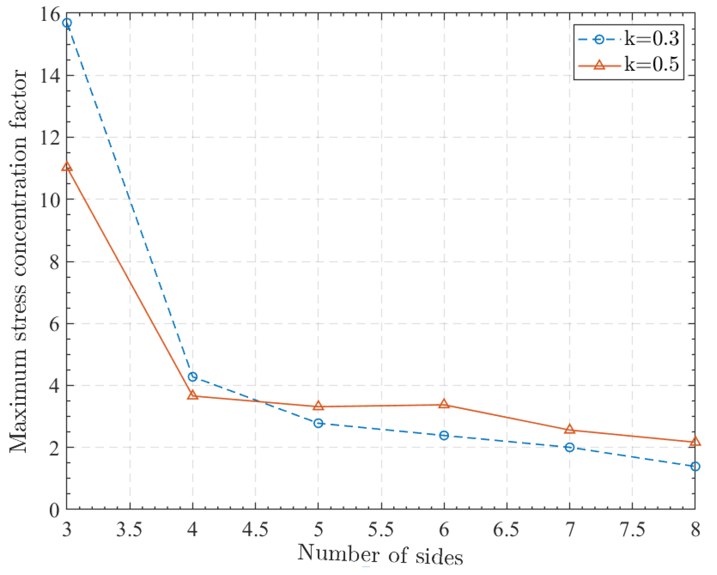
The maximum value of the dynamic stress concentration coefficient of the regular polygon is obtained at its vertices. It can be seen that the dynamic stress concentration of the regular polygon is mainly significant at the vertices.
The maximum value of the dynamic stress concentration factor of the regular m-gon decreases with the increase in m, and the speed of change is first fast and then slow. Since the increase of m leads to an increase of the vertices of the regular m-polygon, the dynamic stress concentration is more dispersed and moderate, and the maximum value of the dynamic stress concentration is also smaller.
The theoretical and numerical results presented in this paper are expected to be applied to the dynamic analysis and strong design of piezoelectric ceramic structures, and provide suggestions for the subsequent large-scale application and production of BCTS materials. By changing the piezoelectric material constant and the conformal transformation formula, the DSCF of any hole in any piezoelectric material can theoretically be obtained.
Author Contributions
Conceptualization, C.Z. and H.J.; methodology, J.L.; validation, J.L., J.F. and X.H.; formal analysis, Y.G.; investigation, W.Z. and J.L.; data curation, J.L. and J.B.; writing—original draft preparation, J.L.; writing—review and editing, C.Z.; supervision, H.J.; project administration, Y.G.; funding acquisition, W.Z. and J.N. All authors have read and agreed to the published version of the manuscript.
Funding
This research was supported by the Sichuan Science and Technology Program (No. 2022YFG0274), the Key Research and Development Program of Zhejiang Province (No. 2021C03013), the National Natural Science Foundation of China (Grant No. 51875146), the Natural Science Foundation of Zhejiang Province (Grant No. LY21E050005), and the Key Laboratory for Technology in Rural Water Management of Zhejiang Province (ZJWEU-RWM-20200303B).
Institutional Review Board Statement
Not applicable.
Informed Consent Statement
Not applicable.
Data Availability Statement
Not applicable.
Conflicts of Interest
The authors declare no conflict of interest.
References
- Rödel, J.; Jo, W.; Seifert, K.T.P.; Anton, E.-M.; Granzow, T.; Damjanovic, D. Perspective on the Development of Lead-free Piezoceramics. J. Am. Ceram. Soc. 2009, 92, 1153–1177. [Google Scholar] [CrossRef]
- Apc International. Piezoelectric Ceramics; APC International: Mackeyville, PA, USA, 1971. [Google Scholar]
- Aj, M.; Herbert, J. Electroceramics: Materials, Properties, and Applications; Chapman Hall: London, UK, 1990; p. 82. [Google Scholar]
- Uchino, K. Piezoelectric Actuator/Ultrasonic Motors; Kluwer Academic: Boston, MA, USA, 1996. [Google Scholar]
- Setter, N. Piezoelectric Materials and Devices; Ceramics Laboratory, EPFL Swiss Federal Institute of Technology: Lausanne, Switzerland, 2005. [Google Scholar]
- Li, Z.; Peng, X.; Hu, G.; Zhang, D.; Xu, Z.; Peng, Y.; Xie, S. Towards real-time self-powered sensing with ample redundant charges by a piezostack-based frequency-converted generator from human motions. Energy Convers. Manag. 2022, 258, 115466. [Google Scholar] [CrossRef]
- Li, Z.; Peng, X.; Hu, G.; Peng, Y. Theoretical, numerical, and experimental studies of a frequency up-conversion piezoelectric energy harvester. Int. J. Mech. Sci. 2022, 223, 107299. [Google Scholar] [CrossRef]
- Kounga, A.B.; Granzow, T.; Aulbach, E.; Hinterstein, M.; Rödel, J. High-temperature poling of ferroelectrics. J. Appl. Phys. 2008, 104, 024116. [Google Scholar] [CrossRef]
- Donnelly, N.J.; Shrout, T.R.; Randall, C.A. Addition of a Sr, K, Nb (SKN) Combination to PZT(53/47) for High Strain Applications. J. Am. Ceram. Soc. 2007, 90, 490–495. [Google Scholar] [CrossRef]
- Parajuly, K.; Habib, K.; Liu, G. Waste electrical and electronic equipment (WEEE) in Denmark: Flows, quantities and management. Resour. Conserv. Recycl. 2017, 123, 85–92. [Google Scholar] [CrossRef]
- Deffree, S. Korea ROHS combines EU ROHS, WEEE, ELV. Edn 2007, 52, 86. [Google Scholar]
- Hong, C.H.; Kim, H.P.; Choi, B.Y.; Han, H.S.; Jo, W.J. Lead-free piezoceramics—Where to move on? J. Mater. 2016, 2, 1–24. [Google Scholar] [CrossRef]
- Saito, Y.; Takao, H.; Tani, T.; Nonoyama, T.; Takatori, K.; Homma, T.; Nagaya, T.; Nakamura, M. Lead-free piezoceramics. Nature 2004, 432, 84–87. [Google Scholar] [CrossRef]
- Rödel, J.; Webber, K.G.; Dittmer, R.; Jo, W.; Kimura, M.; Damjanovic, D. Transferring lead-free piezoelectric ceramics into application. J. Eur. Ceram. Soc. 2015, 35, 1659–1681. [Google Scholar] [CrossRef]
- Shrout, T.R.; Zhang, S.J. Lead-free piezoelectric ceramics: Alternatives for PZT? J. Electroceram. 2007, 19, 113–126. [Google Scholar] [CrossRef]
- Boljanović, S.; Maksimović, S.; Djurić, M. Fatigue strength assessment of initial semi-elliptical cracks located at a hole. Int. J. Fatigue 2016, 92, 548–556. [Google Scholar] [CrossRef]
- Sosa, H. Plane problems in piezoelectric media with defects. Int. J. Solids Struct. 1991, 28, 491–505. [Google Scholar] [CrossRef]
- Liu, W.; Ren, X. Large Piezoelectric Effect in Pb-Free Ceramics. Phys. Rev. Lett. 2009, 103, 257602. [Google Scholar] [CrossRef] [Green Version]
- Smith, F.; Kullgren, T. Theoretical and Experimental Analysis of Surface Cracks Emanating from Fastener Holes; Colorado State University Fort Collins Department of Mechanical Engineering: Fort Collins, CO, USA, 1977. [Google Scholar]
- Kim, J.-H.; Lee, S.-B.; Hong, S.-G. Fatigue crack growth behavior of Al7050-T7451 attachment lugs under flight spectrum variation. Theor. Appl. Fract. Mech. 2003, 40, 135–144. [Google Scholar] [CrossRef]
- Liang, Y.-C.; Sun, Y.-P.; Wu, L.-N. Hole Problems in a Circular Piezoelectric Plate. Trans. Can. Soc. Mech. Eng. 2016, 40, 491–500. [Google Scholar] [CrossRef]
- Hechmer, J.L.; Bloom, J.M. Determination of stress intensity factors for the corner cracked hole using the isoparametric singularity element. Int. J. Fract. 1977, 13, 732–735. [Google Scholar] [CrossRef]
- Newman, J. Stress-Intensity Factor Equations for Cracks in Three-Dimensional Finite Bodies Subjected to Tension and Bending Loads; Langley Research Center, National Aeronautics and Space Administration: Hampton, VA, USA, 1984; Volume 85793.
- Wang, Y.; Gao, C. The anti-plane solution for the cracked equilateral triangle hole in transverse isotropic piezoelectric materials. Chin. J. Appl. Mech. 2015, 32, 973–978. [Google Scholar] [CrossRef]
- Shiwang, F.; Junhong, G. Anti-plane problem of an edge crack emanating from a triangle hole in one⁃ dimensional hex-agonal piezoelectric quasicrystals. Chin. J. Appl. Mech. 2016, 33, 421. [Google Scholar] [CrossRef]
- Yang, J.; Li, X. Analytic solutions of problem about a circular hole with a straight crack in one-dimensional hexagonal quasicrystals with piezoelectric effects. Theor. Appl. Fract. Mech. 2016, 82, 17–24. [Google Scholar] [CrossRef]
- Fan, S.; Guo, J.; Yu, J. Anti-plane problem of four edge cracks emanating from a square hole in piezoelectric solids. Chin. J. Aeronaut. 2017, 30, 461–468. [Google Scholar] [CrossRef] [Green Version]
- Wang, Y.-J.; Gao, C.-F.; Song, H. The anti-plane solution for the edge cracks originating from an arbitrary hole in a piezoelectric material. Mech. Res. Commun. 2015, 65, 17–23. [Google Scholar] [CrossRef]
- Crowdy, D. The Schwarz–Christoffel mapping to bounded multiply connected polygonal domains. Proc. R. Soc. A Math. Phys. Eng. Sci. 2005, 461, 2653–2678. [Google Scholar] [CrossRef]
- Pao, Y.-H.; Mow, C.-C.; Achenbach, J.D. Diffraction of Elastic Waves and Dynamic Stress Concentrations. J. Appl. Mech. 1973, 40, 872. [Google Scholar] [CrossRef] [Green Version]
- Wang, S.; Mou, F.; Liu, Q. Microstructure and electrical performance of Sm2O3-doped BCTSG lead-free ceramics. Ceram. Int. 2022, 48, 15152–15164. [Google Scholar] [CrossRef]
| Publisher’s Note: MDPI stays neutral with regard to jurisdictional claims in published maps and institutional affiliations. |
© 2022 by the authors. Licensee MDPI, Basel, Switzerland. This article is an open access article distributed under the terms and conditions of the Creative Commons Attribution (CC BY) license (https://creativecommons.org/licenses/by/4.0/).


 ,
, 