Article

Performance Analysis of Magnetorheological Damper with Folded Resistance Gaps and Bending Magnetic Circuit

Key Laboratory of Conveyance and Equipment, Ministry of Education, East China Jiaotong University, Nanchang 330013, China
*
Author to whom correspondence should be addressed.
Actuators 2022, 11(6), 165; https://doi.org/10.3390/act11060165
Submission received: 29 May 2022 / Revised: 11 June 2022 / Accepted: 14 June 2022 / Published: 15 June 2022
(This article belongs to the Special Issue Smart Materials in Robotics and Actuators)

Abstract

:
The traditional magnetorheological (MR) damper subject to the limited space has shortcomings such as small damping force, narrow dynamic range and low adaptability. In this study, a new MR damper with folded resistance gaps and bending magnetic circuit was proposed for improving the damping performance. The length of the resistance gap was increased by configuring the multi-stage folded annular gap structure, and the magnetic circuit was established to activate the non-flux region. The mathematical model was established for the MR damper to analyze the damper force, magnetic circuit and dynamic performance. Subsequently, the finite element analysis (FEA) methodology was utilized to investigate the changes of magnetic flux densities in the folded resistance gaps. The test rig was setup to explore and verify the dynamic performance of the proposed MR damper under different excitation conditions. The results indicate the maximum damping force is approximately 4346 N at the current of 1.5 A, frequency of 0.25 Hz and amplitude of 7.5 mm. The damping force and dynamic range of the proposed MR damper are enhanced by 55.82% and 62.21% compared to that of the traditional MR damper at the applied current of 1.5 A, respectively, thus highlighting its high vibration control ability.

1. Introduction

Magnetorheological (MR) damper is widely employed for semi-active control in the vibration isolation systems, including the automobile [1,2,3,4], civil structures [5,6,7], aerospace [8,9,10] and prosthetic knees [11,12]. With the MR fluid as the working medium, the MR damper efficiently achieves the continuous damping control, fast response speed, and low energy consumption [13,14,15,16].
The structural configuration is an important property that affects the damping characteristics of the MR damper [17,18]. However, the traditional MR damper is unable to provide large damping forces under dimensional constraints due to the simple structure with low utilization rate of magnetic field and gap. Facing this challenge, strides have been made continuously on the structural design of the MR damper mainly focusing on the improving the magnetic supply system [19,20,21,22,23], selecting the working mode of the MR fluid [24,25,26] and optimizing the flow channel layout [27,28,29,30,31,32,33,34].
Improving the magnetic supply system includes the arrangement of multiple coils, the design of the embedded permanent magnet and the optimization of the magnetic circuit distribution. Bai et al. [19] developed an MR damper with five excitation coils equipped at the inner bypass valve of the concentric tube and led to six damping gaps. This design increased the dynamic range and reduced the field-off damping force over the operational velocity range of 0–5.2 m/s. Aydar et al. [21] designed an MR damper in which a permanent magnet was embedded. The simulation results show that the output damping force of the MR damper could be increased by 100% through enhancing the magnetic field. Cheng et al. [22] presented an MR damper featuring a meandering magnetic circuit with the damping force range increased by 1.8 times than that of the conventional MR damper. The experimental results show that this design could provide damping force as high as 3400 N with an excitation velocity of 0.0628 m/s. Idris [23] designed an MR damper with a serpentine flux external concentric bypass valve with the dynamic range increased by 1.5 times higher than that of the traditional structure.
The working mode of the MR damper contains the flow mode, the shear mode and the squeeze mode. Yazid et al. [24] suggested an MR damper combined with squeeze and shear modes, experimentally compared the damping performance in different conditions. The comparison results show that the mixed mode could obtain higher damping force than the single mode MR damper. Mughni et al. [25] proposed and tested a novel MR damper combining the flow and shear flow modes in series. The MR damper can obtain higher force by increasing the number of the effective areas. Ruan et al. [26] developed an MR damper using the squeeze flow mode. The experimental results show that the maximum damping force was approximately 6.5 kN.
Considering the flow channel types, the structure of the MR damper can be classified into the axial flow, radial flow and axial-radial hybrid flow. Bai et al. [29] modeled and tested the annular-radial-duct MR damper. Results show that this design could provide a large damping force of 3149 N with an excitation velocity of 0.19 m/s. In addition, a large damping force range (140–3149 N) was achieved under a corresponding excitation velocity range (0.025–0.19 m/s). Wang et al. [30] designed an MR damper with bifold valve as inner bypass, which had the axial and radial damping channels. The maximum damping force reaches 3600 N at the current of 1.5 A. However, the radial gap increases the piston radius to a certain extent, leading to the excessive radial size of the MR damper. Kim et al. [32] introduced a bifold flow mode MR damper with two axial flow gaps in the piston connecting through the feedback hole. The experimental damping force reaches 3150 N, and the equivalent damping force was more than twice that of the traditional MR damper. Hu et al. [34] proposed, manufactured and tested an MR damper with serial-type flow channels, which had multiple axial annular channels. The maximum positive damping force reaches 5486 N and the dynamic adjustable range reaches to 7.
In traditional structural designs, obtaining larger damping forces requires increasing the length of piston, layout of radial flow channels, internal or external bypass arrangement, multiple exciting coil and embedding a permanent magnet. However, these methods increase the axial or radial dimensions of MR dampers, while causing challenges for obtaining much more superior damping characteristics under space constraints. In addition, the multiple exciting coil and embedding permanent magnet increase the complexity of the MR damper. Regarding to the compact configurations, some designs are widely used, such as the layout of meandering magnetic circuit and folded flow channels.
There is research using meandering magnetic circuit, but the method of serpentine flux path is almost always used in MR brakes and MR dampers with a bypass valve. For extending the effective gap length, the layout of folded flow channels needs further exploration. Combining the above two designs should be considered to achieve better performance, such as combining the axial folding flow channel and bending the magnetic circuit inside the piston. This is rarely considered in the above literature, wherein the research on MR dampers using the meandering flow and flux path method is not available.
In this work, a new MR damper configuration with folded resistance gaps and bending magnetic circuits was proposed, aiming to obtain a larger controllable damping force subject to the limited volume constraint. This configuration combines the characteristics of the folded resistance gaps and bending magnetic circuit, both of which were integrated in the damper piston instead of the bypass. The mathematical model of the MR damper was correspondingly established, and the electromagnetic properties were analyzed using the finite element method. Then, the damping force performance of the proposed MR damper was evaluated under different current values, and the simulated results were naturally compared with the traditional configuration. The test rig was established to validate the modeling results.

2. Design of the Proposed MR Damper

2.1. Structural Principle and Design

Figure 1 shows the structural principles of the traditional MR damper and the MR damper proposed in this work. The flow gap in which the magnetic circuit passes through vertically is the effective gap. As shown in Figure 1a, the magnetic circuit divides the flow gap of a traditional MR damper into two parts: two short effective gaps and a long non-flux gap. The controllable damping force rises accordingly with the rising length of effective gap. This design has both serpentine flow gaps and bending magnetic circuit, as shown in Figure 1b. The folded resistance gaps increase the length of the effective damping gap, while shortening the axial size of the piston. Compared to the MR damper with the radial damping gap, the radial dimension of the damper is also significantly decreased. In addition, the bending magnetic circuit activates the non-flux gap of the traditional extra, and increases the length of the second outer effective gap. This design improves the activation rate of the flow gap, and increases controllable damping force and dynamic range.
There are some essential differences between this configuration and others. The proposed MR damper improves in terms of both the distribution of the magnetic circuit and the flow path; however, the other dampers only have improvement in terms of one. A typical example is the MR damper with a serial-type flow path proposed in [32]. In addition, compared with the above damper, the proposed damper structure provides less non-flux gap and more coil turns.
Figure 2 illustrates the structure of the proposed MR damper with folded resistance gaps and bending magnetic circuits. This double-ended MR damper mainly composed of two piston rods, two end covers, cylinder, piston assembly and end shield. The piston assembly includes the inner magnetic sleeves, middle magnetic sleeves, outer magnetic sleeves, exciting coil, non-magnetic ring, magnetic semicircles, non-magnetic disks and magnetic core. The magnetic core and the magnetic sleeves are made of No. 10 steel. The non-magnetic ring, non-magnetic disks, end covers, cylinder and piston rods are made of non-magnetic materials of stainless steel. The inner gap is composed of a magnetic core and an inner magnetic sleeve. The middle gap is composed of an inner magnetic sleeve and a middle magnetic sleeve. The first outer gap is composed of a middle magnetic sleeve and an outer magnetic sleeve. The second outer gap is formed between the outer magnetic sleeve and the magnetic semicircle. The inner, middle and outer gaps are axial gaps. There are four convexities at the opposite end of the inner magnetic sleeves and the middle magnetic sleeves, which are used to form the radial gaps. These axial gaps and radial gaps are connected in series to form a folded resistance gap. In addition, the grooves and convexities of each part of the piston assembly are matched to ensure the uniform thickness of the flow gap. The two magnetic semicircles are external magnetic elements of the excitation coil, which is designed as two semicircular blocks to facilitate the winding of the excitation coil.
When the MR damper works, the piston motion makes the MR fluid in the compression chamber squeeze into another chamber through the flow gap. When the current acts on the exciting coil, the MR effect of the MR fluid is produced, and the controllable damping force is established in the folded resistance gaps.

2.2. Magnetic Circuit of the Developed MR Damper

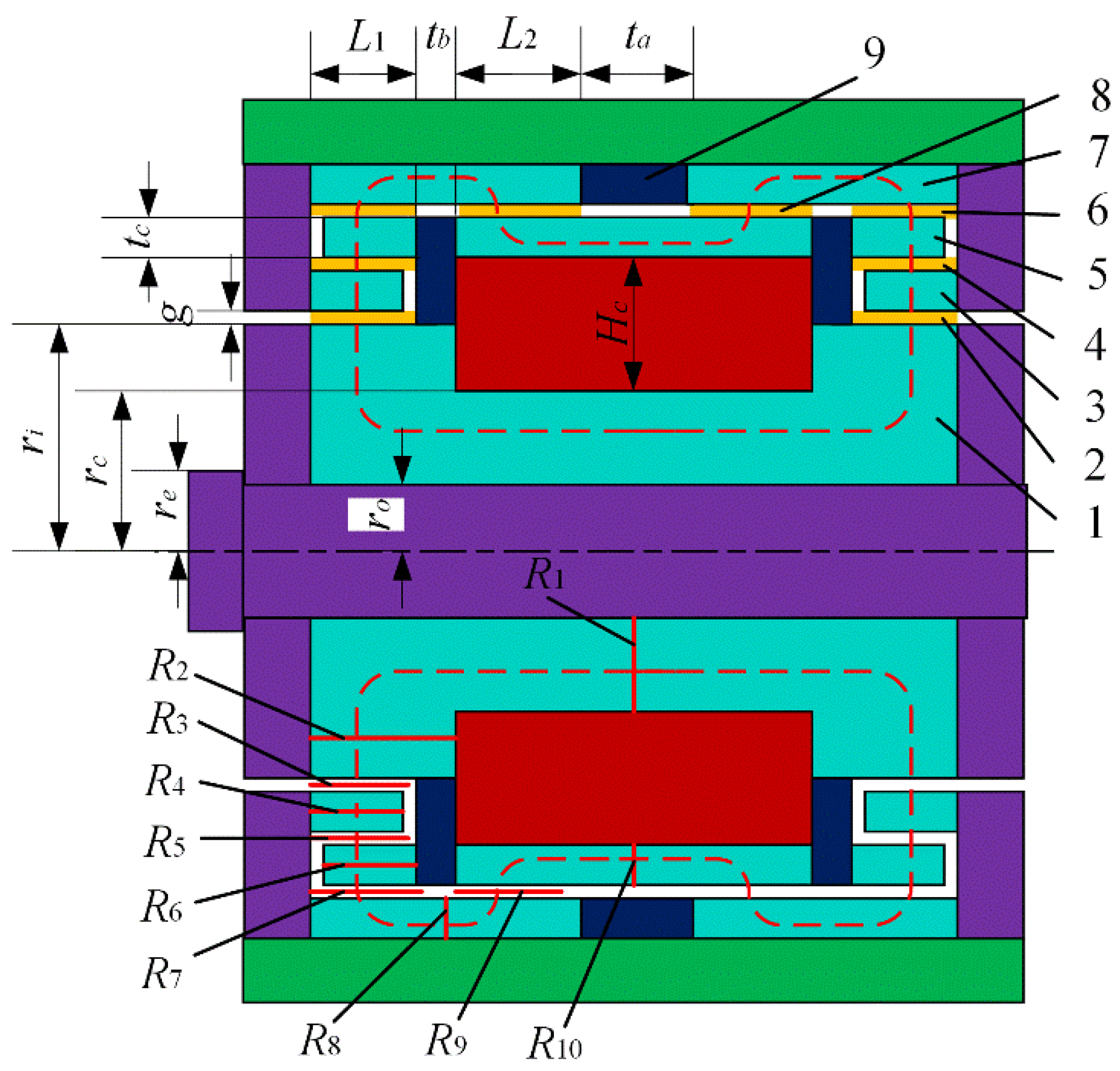
Figure 3 displays the magnetic circuit diagram of the proposed MR damper. The magnetic sleeves and non-magnetic ring are strategically placed on both sides of the outer gap, which forces the magnetic flux line to bend and pass through the outer gap four times. The magnetic flux line passes through the magnetic core, inner gap, inner magnetic sleeve, middle gap, middle magnetic sleeve, first outer gap and outer magnetic sleeve in sequence. The magnetic flux line moves axially in the outer magnetic sleeve, while it is bent by the non-magnetic ring. The magnetic flux line returns to the magnetic core through the second outer gap, the magnetic semicircle, and the symmetrical path at the other end of the piston assembly to form a closed magnetic circuit. Hence, the MR fluid with most of the length in the outer gap can be activated.
According to the Kirchhoff’s law, the magnetomotive force of the magnetic circuit gives:
N c I = c H d l = i = 1 n H i l i
where Nc is the number of turns of exciting coil, I is the applied current, Hi and li represent the magnetic field intensity and the effective length of part i in magnetic circuit, respectively.
The total magnetic flux is expressed as:
Φ = B d S = B i S i
where Bi and Si represent the magnetic flux density and cross-sectional area of part i in magnetic circuit, respectively.
The relationship between magnetic flux density Bi and magnetic field intensity Hi is given by:
B i = μ o μ i H i
where μo is the air permeability and μi is the relative permeability of magnetic materials in each part.
The effective components magnetoresistance in the equivalent closed magnetic circuit can be expressed as:
R i = l i μ o μ i S i
According to the magnetic flux direction shown in Figure 3, the magnetic circuit can be equivalent to a series circuit, and the total reluctance is equal to the sum of the reluctance of each part. Since the reluctance is symmetrically arranged at both ends of the piston assembly, the total reluctance Rm can be expressed as:
R m = R 1 + 2 2 9 R i + R 10
Combining Equations (1)–(4):
N c I = i = 1 n B i μ o μ i l i = i = 1 n l i μ o μ i S i Φ = i = 1 n R i Φ
The magnetic flux density Bi of each part of the magnetic circuit is:
B i = Φ S i = N c I S i i = 1 n R i

2.3. Design of Main Structural Dimensions

In this paper, the design of the MR damper with folded resistance gap and curved magnetic circuit is to change the magnetic field structure to make the magnetic flux line pass through the multi-stage meandering damping flow channel; consequently, the design of the flow channel is the design focus of this research. Since the shear yield stress that can be achieved by each effective damping gap in the multi-stage serpentine flow channel is closely related to the size of the damper, in order to make each effective damping gap reach the saturated shear stress under the same current and time, as far as possible, we make the magnetic flux densities generated in the flow channel approximately equal, and then it can be deduced that the cross-sectional area of each effective damping channel is also equal. After that, the structural parameters of the damper can be preliminarily determined according to the external dimensions of the traditional damper and fully considering the installation space of the damper and the strength of external parts such as the damper cylinder and piston rod. After that, considering the reliability of the assembly of each part, the main parameters of the proposed MR damper can be obtained.
Table 1 lists the main structural dimensions of the proposed MR damper. The ratio of the effective damping gap length to the total gap length is defined as the MR gap activation rate. The MR gap activation rate of the proposed MR damper is 66.6% theoretically, which is 21.8% higher than that of the traditional MR damper with the same dimensions. The magnetic circuit achieves the dual effect of increasing the damping force and broadening the dynamic range.

3. Mathematic Modeling of the Proposed MR Damper

The MR damper adopts the flow mode as the working mode, and its damping force mainly comes from the viscous force and yield stress of the MR fluid flowing in the gap. Therefore, the total damping force can be expressed as:
F d = ( Δ P η + Δ P τ ) A p
where Δpη is the viscosity pressure drop, Δpτ is the field-dependent pressure drop due to the yield stress of the MR fluid flowing through the gap, Ap is the effective area of the piston, it can be expressed as:
A p = π r p 2 π [ ( r i + g ) 2 r i 2 ] π r d 2
where rp is the radius of piston, ri is the radius of inner gap, rd is the external radius of piston rod respectively, g is the thickness of gap.
The total pressure drop of the gap includes the field-dependent pressure drop and the viscosity pressure drop. The field-dependent pressure drop is caused by the MR effect of the MR fluid under the shear yield stress. Similarly, the viscosity pressure drop is caused by the MR fluid flow, which is changing basically with the viscosity and flow rate of the MR fluid [27].
Due to the radial gaps being very short, and the fact that the flow direction of the MR fluid in the gap is parallel to the magnetic flux line, only an insignificant damping force is generated, which can be ignored. Considering solely the axial gaps, three-stage gaps could be identified at the inner, middle and outer regions. The pressure drop of each gap can be expressed as:
Δ p g a p = Δ p η + Δ p τ = 6 η q l π g 3 r + c τ l e g
where η is the viscosity of the MR fluid without magnetic field; q is the volumetric flow rate of the MR fluid through the flow gap; l is the length of the flow gap; r is the inner radius of the annular flow gap; c is the correction factor, with a value of 2–3; τ is the shear yield strength of the MR fluid in the flow gap, which is related to the magnetic flux density; le is the length of the effective flow gap.
Accordingly, the pressure drop of the inner annular gap can be expressed as:
Δ p i = 6 η q L 1 π g 3 r i + c τ i L 1 g
where τi is the shear yield strength of the MR fluid in the inner annular gap.
Similarly, the pressure drop of the middle annular gap can be expressed as:
Δ p m = 6 η q L 1 π g 3 r m + c τ m L 1 g
where rm is the radius of the middle annular gap, τm is the shear yield strength of the MR fluid in the middle annular gap.
The viscosity pressure drop of the whole outer annular gap can be expressed as:
Δ p o η = 6 η q ( 2 L 1 + 2 L 2 + t a + 2 t b ) π g 3 r e
where re is the radius of the outer annular gap.
The field-dependent pressure drop due to the yield stress of the outer annular gap can be expressed as:
Δ p o τ = 2 c ( τ f L 1 + τ s L 2 ) g
where τf and τs are the shear yield strength of the MR fluid in the first effective outer gap and the second effective outer gap, respectively.
The total damping force of the proposed MR damper can be given by:
F d = 2 [ 6 η q π g 3 ( L 1 r i + L 1 r m + L 1 + L 2 + t a / 2 + t b r e ) + c L 1 ( τ i + τ m + τ f ) g + c L 2 τ s g ] A p
The dynamic range represents the damping performance of the MR damper, which can be approximately expressed by the ratio of the output damping force to the viscosity damping force. It can be written as:
D = F d Δ p η A p

4. Modeling and Simulation Analysis

4.1. Properties of the MR Fluid

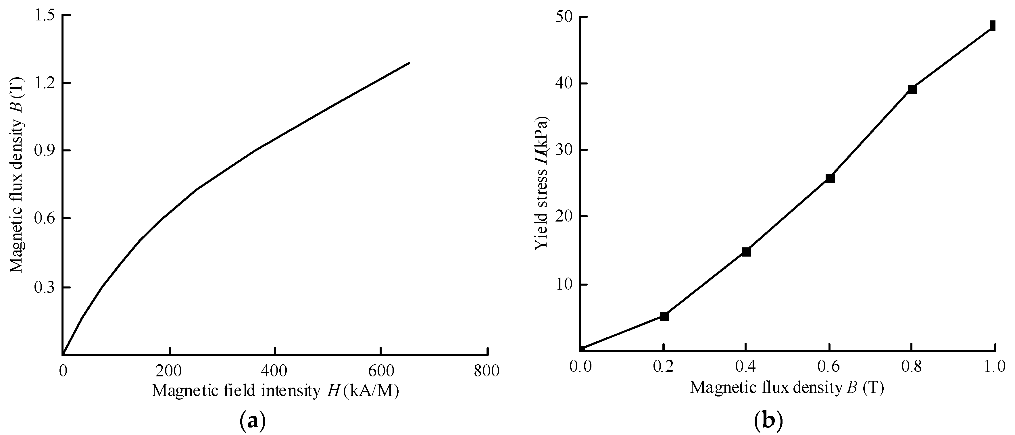
The MRF-J25T MR fluid was used in this work, which was produced by Chongqing Institute of Materials in China [4]. The relationship between magnetic flux density B and shear stress τ is nonlinear, as shown in Figure 4. By using the least square method, the τ-B curve of the MR fluid is fitted by polynomial, and the relationship between shear yield stress and magnetic flux density at the damping gap is obtained
τ = a 3 × B 3 + a 2 × B 2 + a 1 × B
where a1, a2 and a3 indicating the polynomial coefficients of the shear yield stress at the damping gap varying with the magnetic flux densities and a1 = 11.25 kPa/T, a2 = 58.92 kPa/T2, a3 = −24.52 kPa/T3.

4.2. Finite Element Analysis

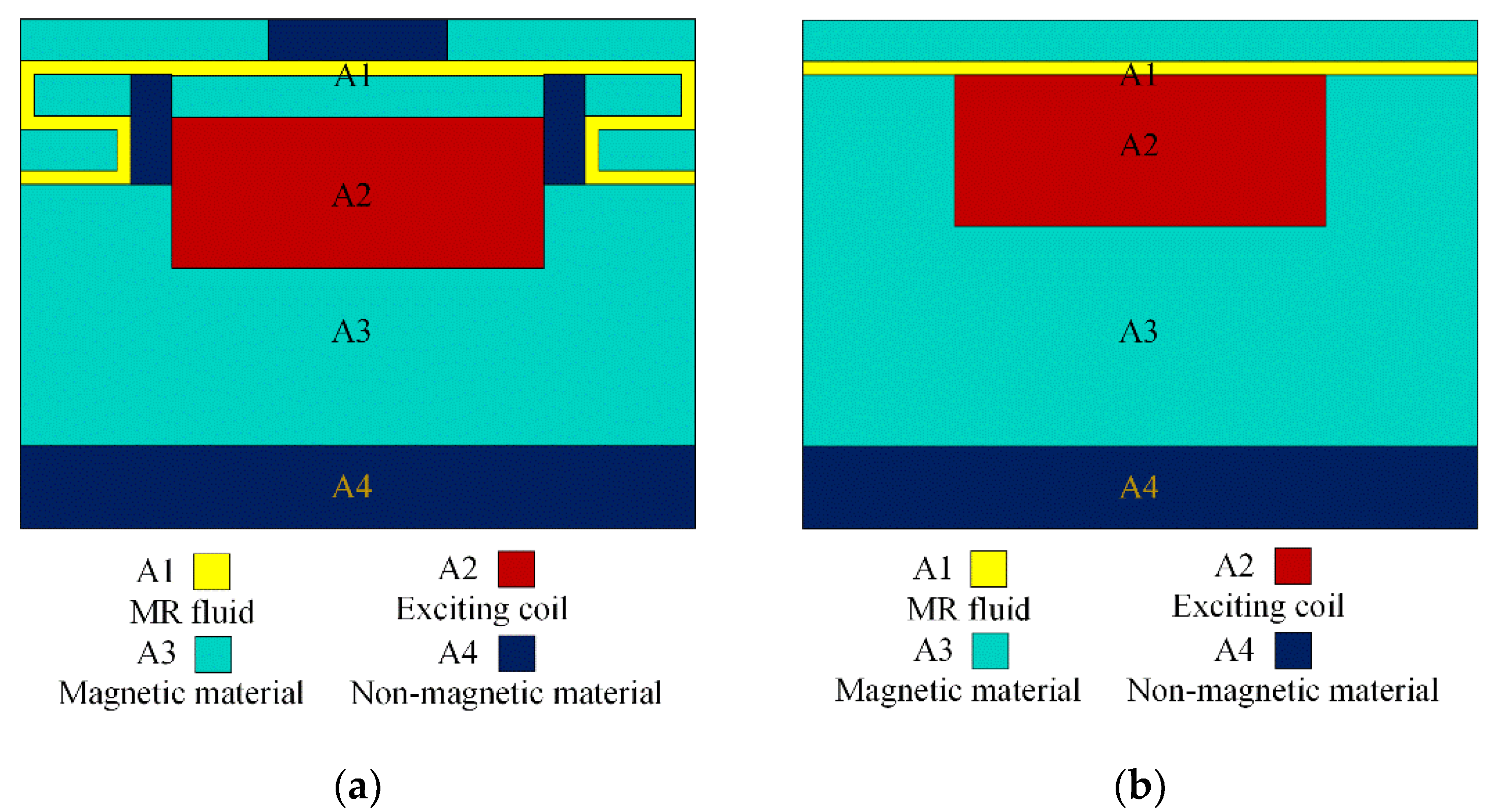
The FEA of the proposed MR damper was carried out to obtain the magnetic flux density under different currents. The damping performance was further analyzed by combining the field-dependent yield stress of the MR fluid and the developed mathematical model. The flow gaps and the exciting coil of the proposed MR damper were integrated in the piston. Therefore, the electromagnetic performance of the piston determines the damping performance of the proposed MR damper. Since the proposed MR damper is an axisymmetric structure, half of the piston model was selected for FEA, as shown in Figure 5a. In addition, a FE model of the traditional MR damper with the same dimensions was established for comparison purposes, as shown in Figure 5b.
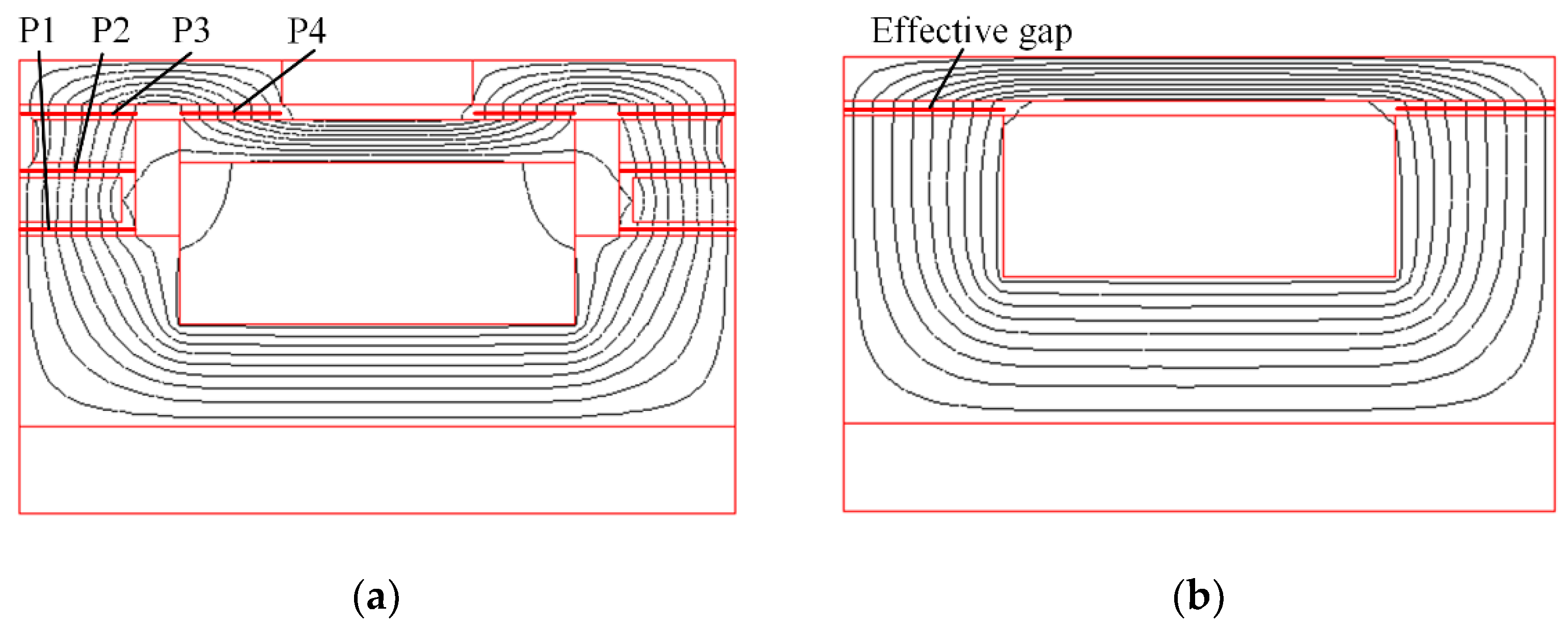
Figure 6 shows the magnetic flux of the designed MR damper and the traditional MR damper with the current of 1.5 A, respectively. In the proposed MR damper, there are inner effective gaps (P1), middle effective gaps (P2) and outer effective gaps (P3) and (P4), which increase the total length of the effective gaps, as shown in Figure 6a. Notably, when the bending magnetic circuit passed through the second outer gaps (P4), there are two sections to be activated effectively, which also contribute to the growth of the total length of the effective gaps. In contrast, there are only two short effective gaps in the traditional damper, as shown in Figure 6b.
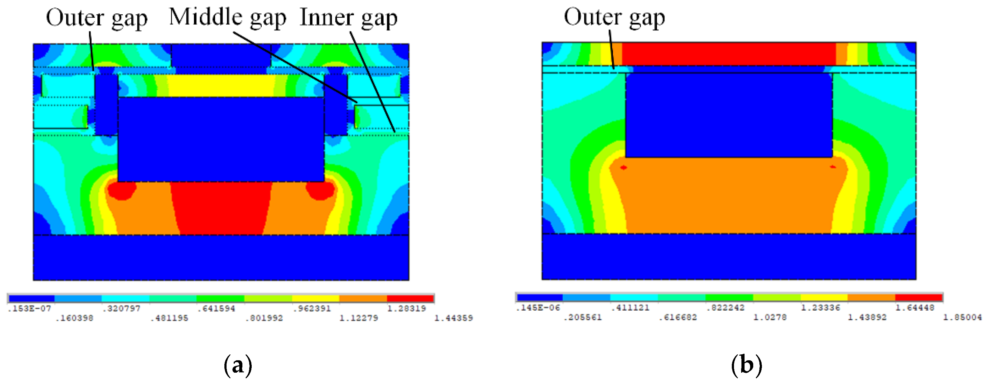
Figure 7 shows the contours of magnetic flux density of the both MR damper at the current of 1.5 A. More than half of the flow path of the traditional MR damper is absent in the magnetic field. However, the inner, middle gaps and majority of outer gaps in Figure 7a are all exposed to the magnetic field. The magnetic flux density of the inner gaps is approximately 0.5 T. The maximum magnetic flux density of the proposed MR damper, which is at the magnetic core, is 1.4 T, while the larger value of 1.8 T is observed in the traditional one, which is close to the magnetic saturation of the magnetic material. The latter has lower magnetic resistance, leading to premature magnetic saturation that can be relatively avoided in the former, that is, the proposed MR damper could achieve a high utilization rate of the magnetic field.
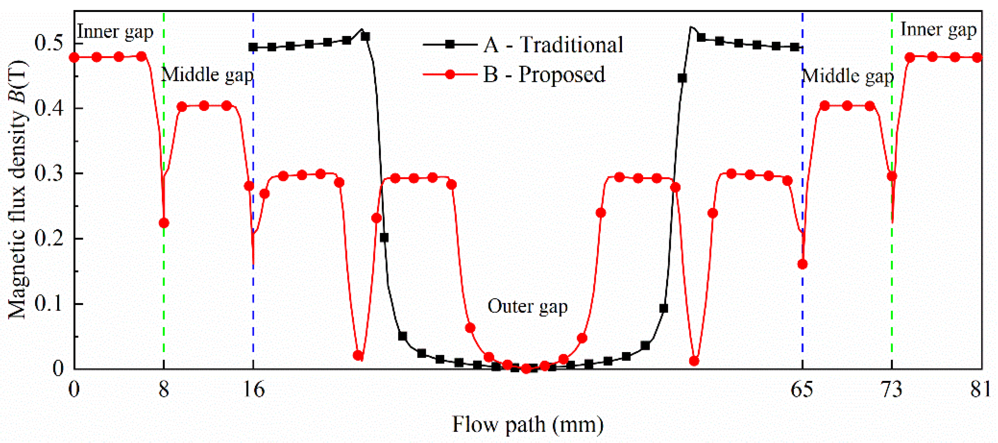
Figure 8 shows the distribution of magnetic flux density value as a function of the annular gap paths of the two MR dampers. The gap path of traditional MR damper is divided into three sections. The magnetic flux density of the two ends of the gap path is nearly 0.5 T. There is no magnetic flux line passing through the middle section in the gap path, where the flux density is close to 0 T. Even though the magnetic flux density in the middle and outer gap of the proposed MR damper is lower to the traditional one, the length of the effective gap in the proposed one visibly extended, owing to the addition of extra inner, middle gaps and the activation of the second outer gaps.
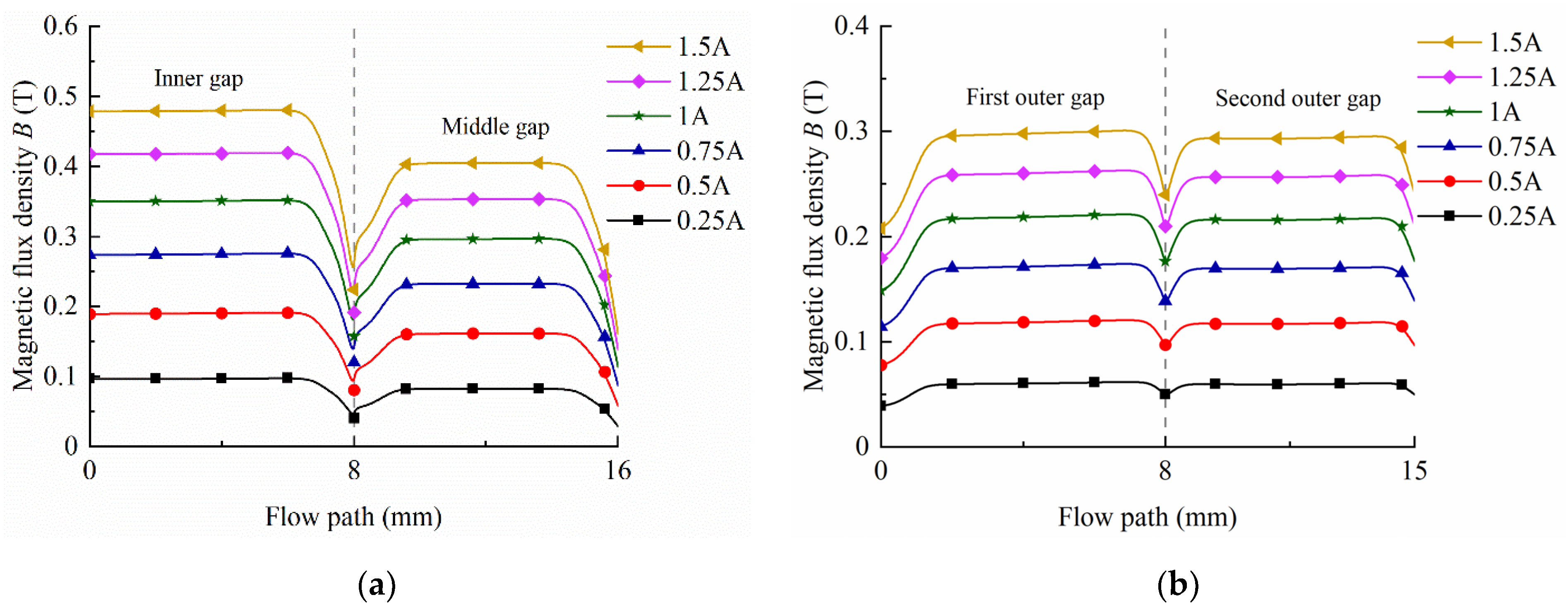
Figure 9 shows the magnetic flux density of each effective gap path for the designed damper with the various current. For all effective gaps, the magnetic flux density of each gap increases with the increase in the applied current. The maximum flux density in the inner gap, middle gap, first outer gap and second outer gap are about 0.49 T, 0.41 T, 0.3 T and 0.3 T with the current of 1.5 A, respectively.
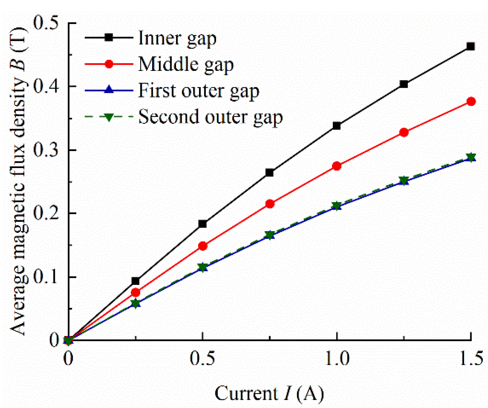
Figure 10 shows the average magnetic flux density obtained by integrating the magnetic flux density of the gap. In the first place, the average magnetic flux density of the folded resistance gaps increases from the outside to the inside because of the decrease in the magnetic flux area under a specific current. That is why the average magnetic flux density of the first outer gap and the second outer gap is approximately the same, as they share identical radii. In addition, as the applied current increases, the average magnetic flux density of each gap increases. Under the applied current of 0.25 A to 1.5 A, the value of the inner gap is about from 0.09 T to 0.46 T, and the middle gap from 0.08 T to 0.38 T, and the outer gaps from 0.06 T to 0.29 T, respectively.
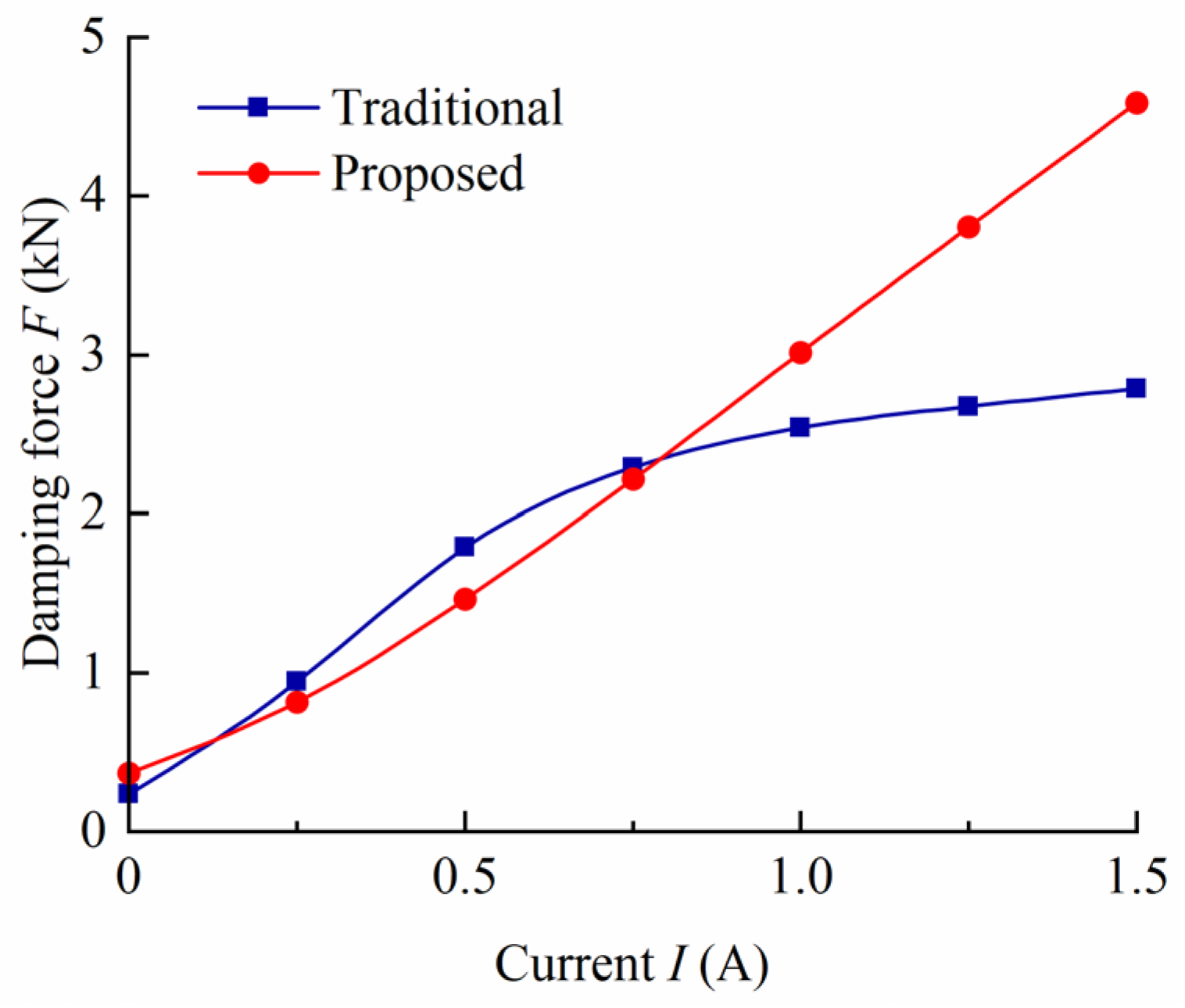
The damping forces for both MR dampers are evaluated by combining the mathematical models and FEA results, as shown Figure 11. Since the total flow gap length of the proposed MR damper is longer than that of the traditional one, the damping force of the former is slightly greater than that of the latter at the current of 0. Meanwhile, though the damping force of the latter is slightly higher than that of the former in the small current range (from 0.25 A to 0.75 A), the output damping force of the proposed one is much greater than the traditional one when the current is larger than 0.75 A. When the current is 1.5 A, the output damping force of the proposed MR damper reaches 4585 N, which is about 1.64 times that of the traditional. Generally speaking, the damping force of the proposed MR damper is approximately linear to the current within the range of 0–1.5 A, while the damping force curve of traditional damper is nonlinear. These indicate that the output damping range of the proposed MR damper is much larger than that of the traditional one.

5. Experimental Analysis and Discussions

5.1. Prototype and Test System Setup

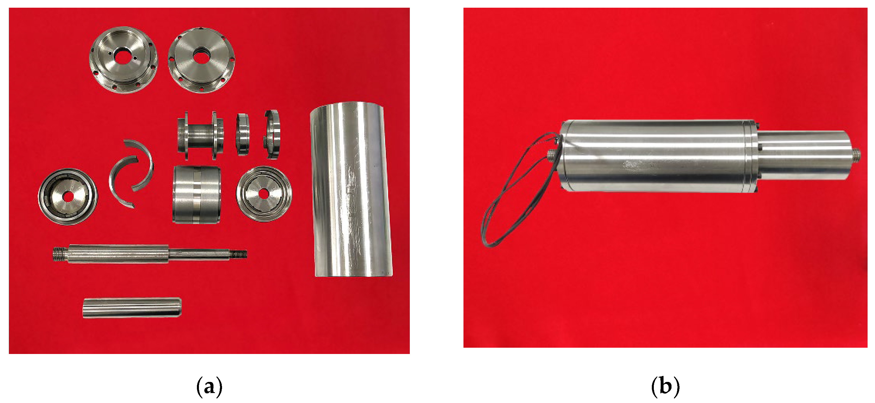
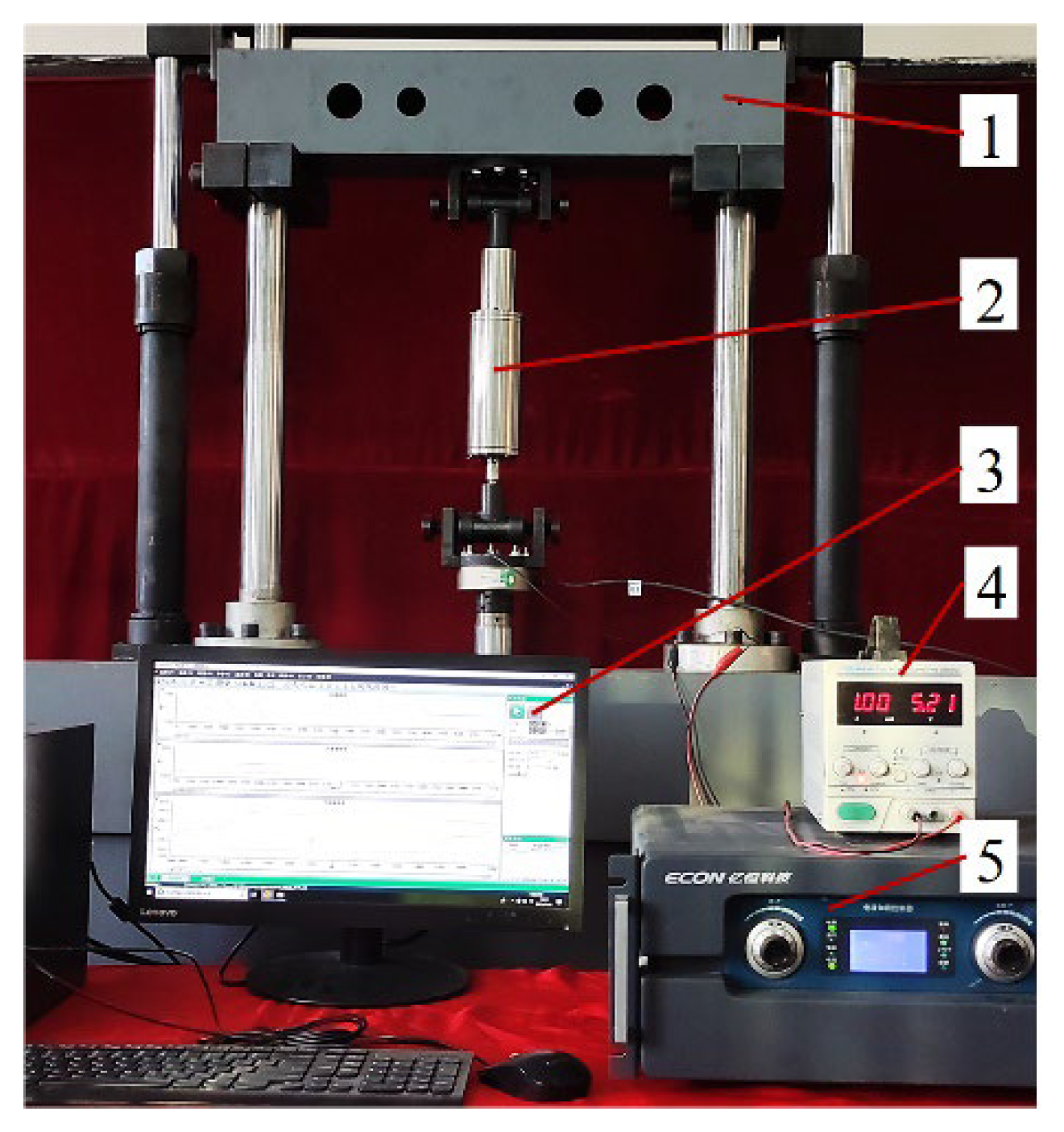
The prototype of the MR damper with folded resistance gaps and bending magnetic circuit was manufactured. The prototype and its components are shown in Figure 12, and the test rig is shown in Figure 13.
The MR damper is installed on the damper test rig equipped with the force sensor and displacement sensor. The DC power supply is used to provide different excitation currents to the MR damper. The electrohydraulic servo controller controlled the vibration excitation platform driving the damper to make the corresponding vibration. The computer that can transmit data with the electrohydraulic servo controller is used to set test parameters, and monitor and store test data.

5.2. Damping Performance Analysis

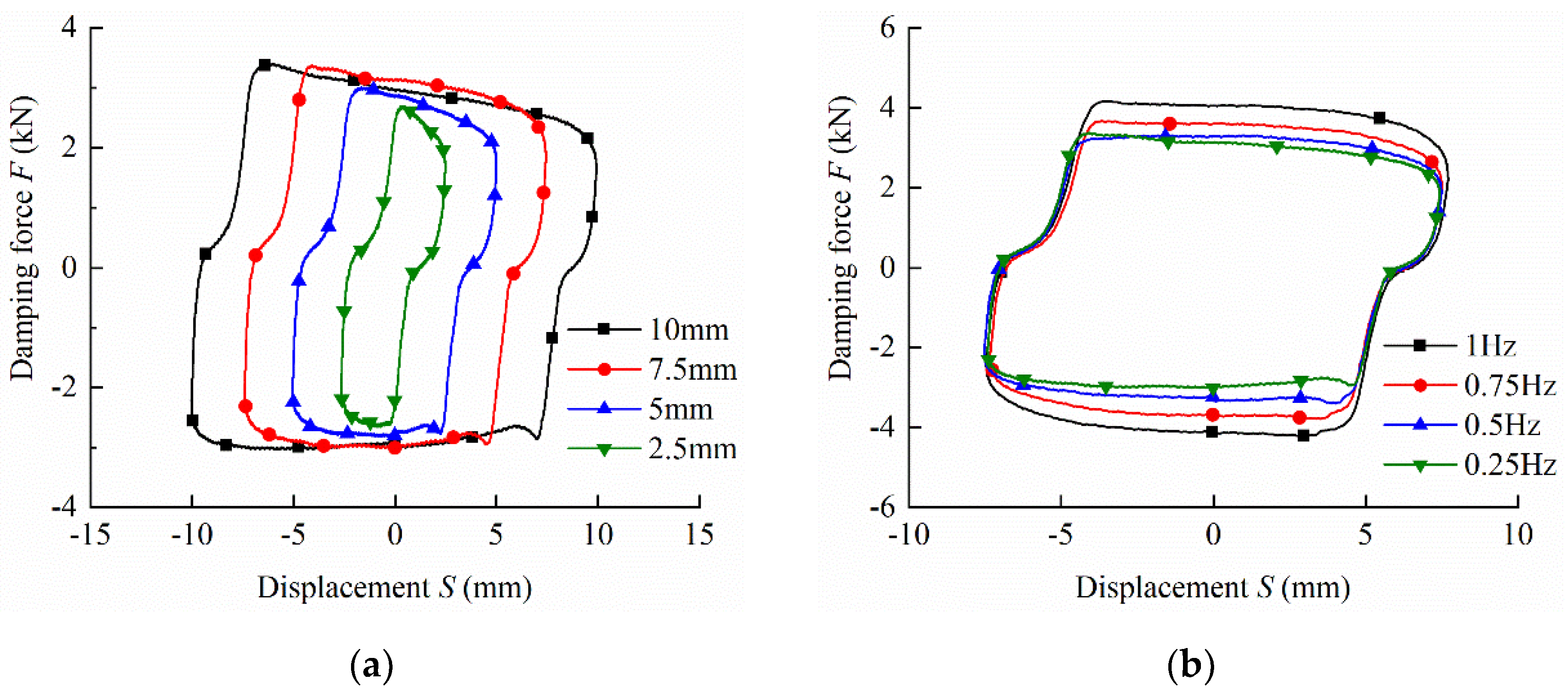
Figure 14a shows the damping force of different amplitudes with the frequency of 0.25 Hz and the current of 1 A; the maximum damping force increases with amplitudes. Figure 14b shows the damping force of different frequencies with the amplitude of 7.5 mm and the current of 1 A; the maximum damping force increases with frequencies. The piston vibration velocity of piston is proportional to the volumetric flow rate. For the positive correlation applies equally to the relation between the volumetric flow rate and viscous damping force, which is explained in Equation (10). Considering the viscous damping force accounts for a small proportion of the total damping force under the low speed excitation, the damping force increases slightly with the amplitude and frequency, as is shown in Figure 14.
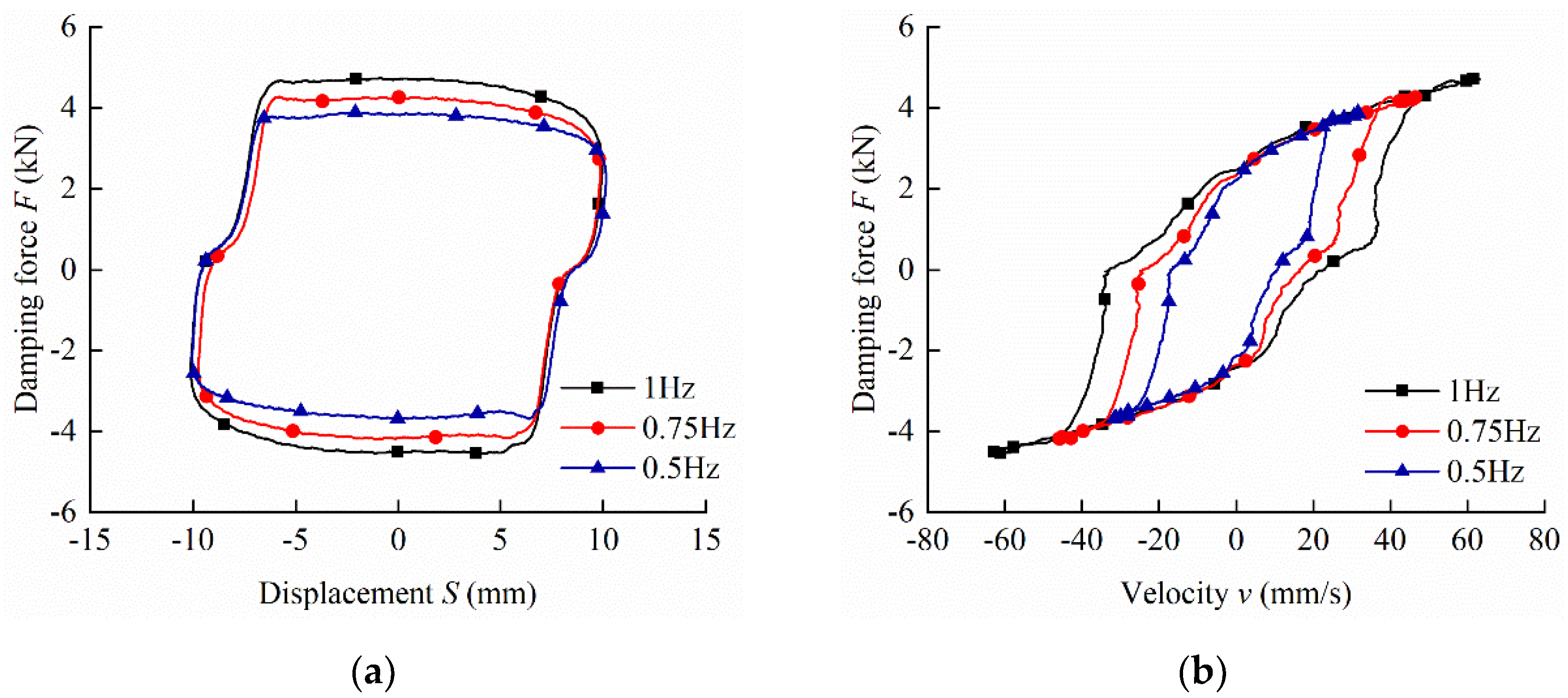
Figure 15 shows the damping force at three frequency levels of 0.5 Hz, 0.75 Hz and 1 Hz with the current of 1 A and the amplitude of 10 mm. Figure 15a verifies the statement in Figure 13 that the variation in damping force and frequency is consistent. When the frequency is 1 Hz, the maximum damping force of the damper is 4739 N. Figure 15b illustrates the relationship between damping force and velocity. The variation curve of maximum damping forces at different frequencies but at the same velocity almost overlaps, namely if the speed and the current are fixed, the output damping forces are roughly the same. The results indicate that the MR damper has a stable damping force and controllability under different exciting conditions.
Moreover, it can be seen from Figure 14 and Figure 15 that the curves of the damping force and displacement have some distortion and are missing in the upper left and lower right parts. This is due to a certain volume of air being mixed into the MR fluid during fluid filling, which leads to a certain empty stroke of the MR damper due to the failure of the timely volume compensation during the working process.
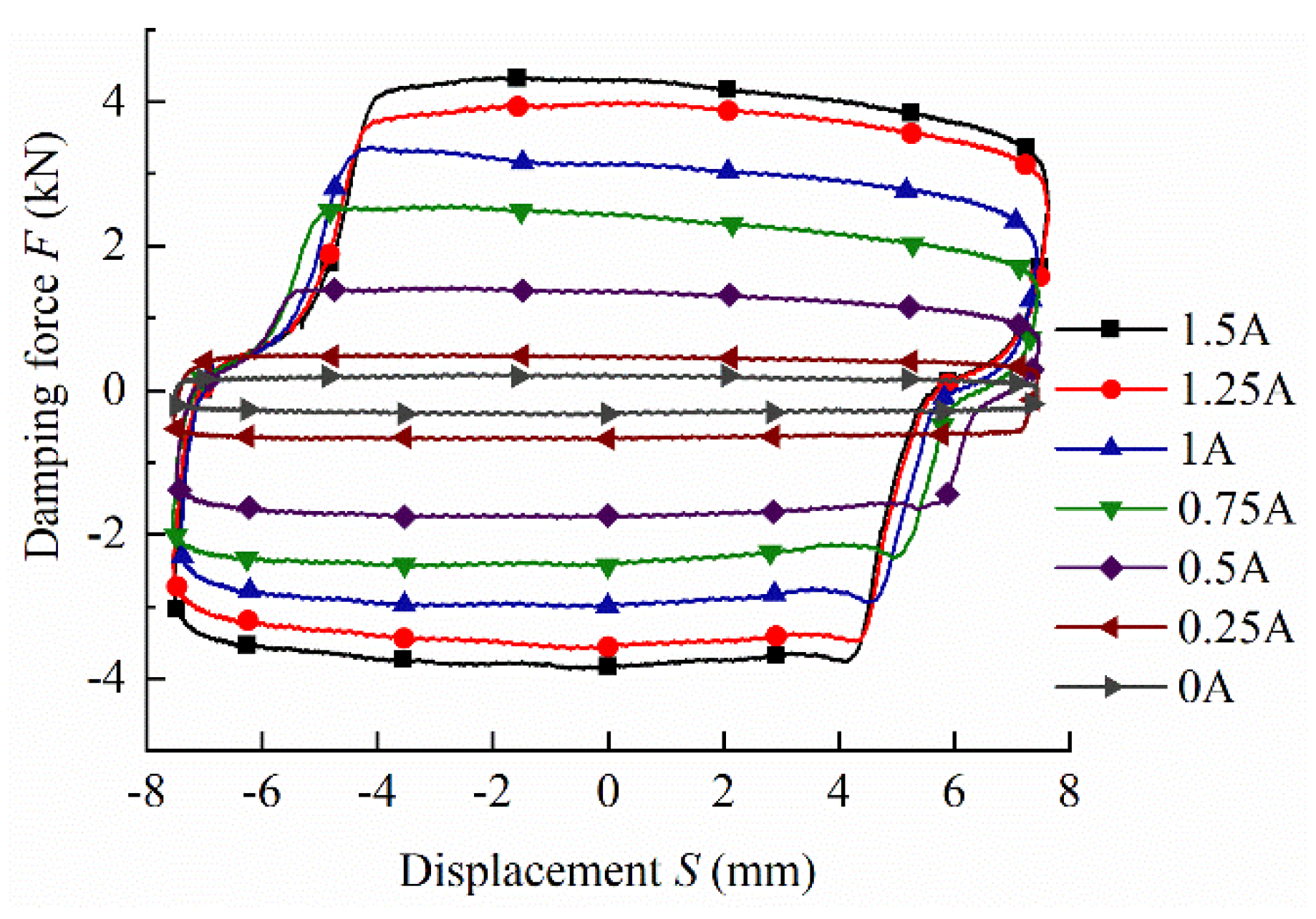
Figure 16 shows the tested output damping force values at a frequency of 0.25 Hz and an amplitude of 7.5 mm for five current levels, namely 0 A, 0.5 A, 0.75 A, 1 A, and 1.5 A. The output damping force increases with the increasing current. When the input current is set to be 0 A and 1.5 A, the corresponding output damping force are 225 N and 4346 N, respectively. The damping force of the proposed MR damper is 1.56 times that of the traditional at the current of 1.5 A. This indicates that the MR damper is able to utilize the magnetic field generated by the excitation coil more effectively, and can provide higher controllable damping force.
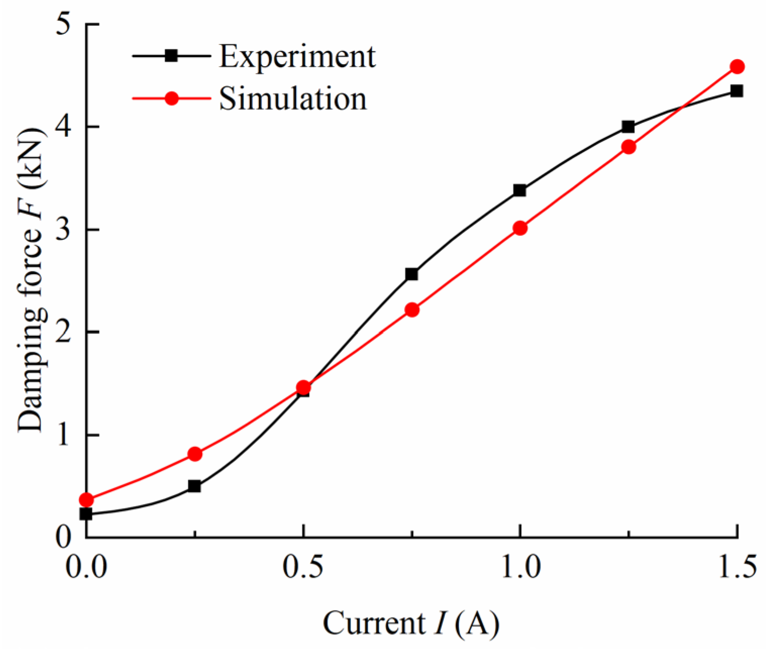
As shown in Figure 17, the simulation and experimental results under different currents were compared to verify the feasibility of the established damping force model. The variation curve of the simulated damping force with current is approximately linear while the linear relationship is not obvious in the experiments. The difference between the model and the experiment was caused by the errors of manufacturing and experiment, and the established model cannot represent the small change in pressure drop. The maximum error is 366 N when the current is 1 A. However, the errors are within the allowable range, and the growth trend of the damping force predicted by the established model is almost the same as measured in the experiments. The damping force of the experimental model and the established model increases with the current. The predicted model established by the Bingham model is simple and easy to implement, so it is suitable for designing the MR damper proposed in this study.
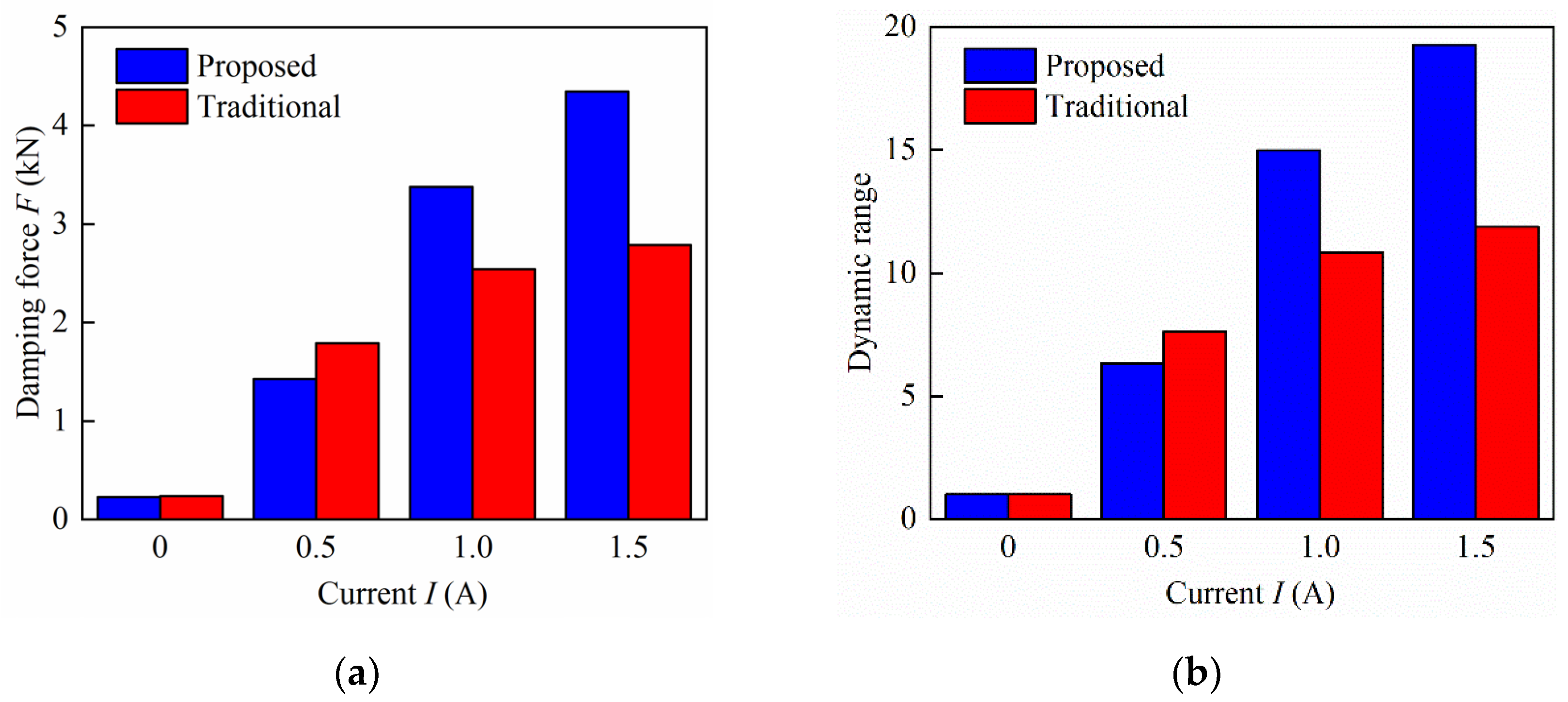
Figure 18 compares the damping force and the dynamic range of the proposed MR damper to that of the traditional MR damper with a frequency of 0.25 Hz and amplitudes of 7.5 mm. It can be seen from the figure that the traditional MR damper can have better damping performance when the applied current is small, because the magnetic flux density of the traditional damper at the damping gap is larger in the state of small current. With the gradual increase in the applied current, the traditional MR damper gradually reaches the magnetic saturation state, and the proposed MR damper continues to increase gradually with an upward trend. Figure 18a shows that the field-off damping force of the former is approximately equal to that of the latter at the current of 0 A. However, the design can provide a significantly larger damping force and dynamic range than the traditional one with both input current of 1.0 A and 1.5 A. The damping force of the proposed MR damper is enhanced by 55.82% compared with the traditional one at the applied current of 1.5 A. In addition, the dynamic range of the former can reach 19.3, enhanced by 62.21% compared with the latter, leading to better damping performance.
To evaluate the damping performance of dampers subject to limited space, it is more feasible and significant to compare the output force per unit volume of dampers than to compare its dimensions directly. Table 2 compares the damping force per unit volume of the proposed MR damper with that of the traditional MR damper and the structures MR damper reported in Reference [32] under sinusoidal displacement excitations with current of 1.5 A. The damping force per unit volume is the ratio between the output damping force and the piston volume of the MR damper. The table shows that the proposed damper has a smaller radius and has a larger damping force per unit volume (2.93 × 10⁴ kN/m3) and dynamic range (19.3).

6. Conclusions

A new MR damper configuration for better damping performance by generating a larger damping force and dynamic range was proposed. The internal structure of folded resistance gaps was designed by placing concentric sleeves based on the constraint of the axial and radial size. The bending magnetic circuit could be guided by laying the magnetic and non-magnetic elements. These two features were combined to improve the magnetic field utilization and the MR gap activation rate. A mathematic model of the proposed MR damper was derived; the magnetic properties were obtained by FEA and compared with the traditional one. Then, the damping force performance of the proposed MR damper was obtained by the mathematic model with magnetic properties. The experimental and simulation results validated the feasibility of the design methodology, indicating a preferable way to design MR dampers under the volume constraint.
A longer effective damping length was designed, leading to an MR activation rate of the gap of 66.6%, which is 21.8% higher than that of the traditional MR damper with the same dimensions. Under the excitation with different velocities and different input currents, the damping performance of the proposed MR damper was tested and analyzed. The experimental results show that the damping force of the MR damper increases with the increasing input current. At the current of 1.5 A, the maximum damping force of the MR damper reaches 4346 N, which enhanced the traditional configuration by 55.82%. Compared to the traditional and referenced configurations, it has a larger damping force per unit volume (2.93 × 10⁴ kN/m3) and the dynamic range, up to 19.3, extended by 62.21% than the traditional one.

Author Contributions

L.L. conducted theoretical analysis and set up the experimental test rig; Y.X. conducted experimental research and wrote the first draft; F.Z. carried out the simulation; G.H. developed the MR damper and revised the paper; and L.Y. completed the data analysis; All authors have read and agreed to the published version of the manuscript.

Funding

This research was funded by the National Natural Science Foundation of China (No. 52165004), Key Project of Natural Science Foundation of Jiangxi Province of China (No. 20212ACB204002).

Conflicts of Interest

The authors declare no conflict of interest.

References

  1. Deng, Z.X.; Wei, X.X.; Li, X.Q.; Zhao, S.E.; Zhu, S.K. Design and multi-objective optimization of magnetorheological damper considering vehicle riding comfort and operation stability. J. Intell. Mater. Syst. Struct. 2021, 10, 1215–1228. [Google Scholar] [CrossRef]
  2. Yang, J.; Ning, D.; Sun, S.S.; Zheng, J.; Lu, H.; Nakano, M.; Zhang, S.; Du, H.; Li, W.H. A semi-active suspension using a magnetorheological damper with nonlinear negative-stiffness component. Mech. Syst. Signal Process. 2021, 147, 107071. [Google Scholar] [CrossRef]
  3. Tang, X.; Du, H.P.; Sun, S.S.; Ning, D.H.; Xing, Z.W.; Li, W.H. Takagi-sugeno fuzzy control for semi-active vehicle suspension with a magnetorheological damper and experimental validation. IEEE Asme Trans. Mechatron. 2017, 22, 291–300. [Google Scholar] [CrossRef]
  4. Hu, G.L.; Wu, L.F.; Deng, Y.J.; Yu, L.F.; Luo, B. Damping performance analysis of magnetorheological damper based on multiphysics coupling. Actuators 2021, 10, 176. [Google Scholar] [CrossRef]
  5. Xu, Z.D.; Xu, Y.W.; Wang, C.; Zhao, Y.L.; Ji, B.H.; Du, Y.L. Force tracking model and experimental verification on a novel magnetorheological damper with combined compensator for stay cables of bridge. Structures 2021, 32, 1971–1985. [Google Scholar] [CrossRef]
  6. He, M.; Zheng, Z.P.; He, B.; Zhu, H. Optimising intelligent control of a highway bridge with magnetorheological dampers. Proc. Inst. Civ. Eng. Struct. Build. 2020, 173, 210–216. [Google Scholar] [CrossRef]
  7. Bhaiya, V.; Bharti, S.D.; Shrimali, M.K.; Datta, T.K. Hybrid seismic control of buildings using tuned mass and magnetorheological dampers. Proc. Inst. Civ. Eng. Struct. Build. 2020, 173, 471–487. [Google Scholar] [CrossRef]
  8. Luong, Q.V.; Jang, D.S.; Hwang, J.H. Semi-active control for a helicopter with multiple landing gears equipped with magnetorheological dampers. Appl. Sci. Basel 2021, 11, 3667. [Google Scholar] [CrossRef]
  9. Wang, C.; Nie, H.; Chen, J.B.; Lee, H.P. The design and dynamic analysis of a lunar lander with semi-active control. Acta Astronaut. 2019, 157, 145–156. [Google Scholar] [CrossRef]
  10. Wang, C.; Chen, J.B.; Li, X.L.; Chen, H.; Nie, H.; Lin, F. Design, dynamic analysis, and experiments of mrf dampers for lunar landers. Adv. Space Res. 2021, 68, 3012–3025. [Google Scholar] [CrossRef]
  11. Huber, M.; Eschbach, M.; Kazerounian, K.; Ilies, H. Functional evaluation of a personalized orthosis for knee osteoarthritis: A motion capture analysis. J. Med. Devices Trans. Asme 2021, 15, 041003. [Google Scholar] [CrossRef]
  12. Zuo, Q.; Zhao, J.P.; Mei, X.; Yi, F.; Hu, G.L. Design and trajectory tracking control of a magnetorheological prosthetic knee joint. Appl. Sci. Basel 2021, 11, 8305. [Google Scholar] [CrossRef]
  13. Lv, H.Z.; Sun, Q.; Zhang, W.J. A comparative study of four parametric hysteresis models for magnetorheological dampers. Actuators 2021, 10, 257. [Google Scholar] [CrossRef]
  14. Rossi, A.; Orsini, F.; Scorza, A.; Botta, F.; Belfiore, N.P.; Sciuto, S.A. A review on parametric dynamic models of magnetorheological dampers and their characterization methods. Actuators 2018, 7, 16. [Google Scholar] [CrossRef] [Green Version]
  15. Zhu, X.C.; Jing, X.J.; Cheng, L. Magnetorheological fluid dampers: A review on structure design and analysis. J. Intell. Mater. Syst. Struct. 2012, 23, 839–873. [Google Scholar] [CrossRef]
  16. Hu, G.L.; Zhang, J.W.; Zhong, F.; Yu, L.F. Performance evaluation of an improved radial magnetorheological valve and its application in the valve controlled cylinder system. Smart Mater. Struct. 2019, 28, 047003. [Google Scholar] [CrossRef]
  17. Ioan, B. Damper with magnetorheological suspension. J. Magn. Magn. Mater. 2002, 241, 196–200. [Google Scholar]
  18. Ioan, B. Magnetorheological suspension electromagnetic brake. J. Magn. Magn. Mater. 2004, 270, 321–326. [Google Scholar]
  19. Bai, X.X.; Hu, W.; Wereley, N.M. Magnetorheological damper utilizing an inner bypass for ground vehicle suspensions. IEEE Trans. Magn. 2013, 49, 3422–3425. [Google Scholar] [CrossRef]
  20. Hu, G.L.; Liu, F.S.; Xie, Z.; Xu, M. Design, analysis, and experimental evaluation of a double coil magnetorheological fluid damper. Shock. Vib. 2016, 2016, 4184726. [Google Scholar] [CrossRef]
  21. Aydar, G.; Wang, X.; Gordaninejad, F. A novel two-way-controllable magneto-rheological fluid damper. Smart Mater. Struct. 2010, 19, 065024. [Google Scholar]
  22. Cheng, M.; Chen, Z.B.; Xing, J.W. Design, analysis, and experimental evaluation of a magnetorheological damper with meandering magnetic circuit. IEEE Trans. Magn. 2018, 54, 1–10. [Google Scholar] [CrossRef]
  23. Idris, M.H.; Imaduddin, F.; Ubaidillah, U.; Mazlan, S.A.; Choi, S.B. A concentric design of a bypass magnetorheological fluid damper with a serpentine flux valve. Actuators 2020, 9, 16. [Google Scholar] [CrossRef] [Green Version]
  24. Yazid, I.I.M.; Mazlan, S.A.; Kikuchi, T.; Zamzuri, H.; Imaduddin, F. Design of magnetorheological damper with a combination of shear and squeeze modes. Mater. Des. (1980–2015) 2014, 54, 87–95. [Google Scholar] [CrossRef]
  25. Mughni, M.J.; Zeinali, M.; Mazlan, S.A.; Zamzuri, H.; Abdul Rahman, M.A. Experiments and modeling of a new magnetorheological cell under combination of flow and shear-flow modes. J. Non-Newton. Fluid Mech. 2015, 215, 70–79. [Google Scholar] [CrossRef]
  26. Ruan, X.; Xuan, S.; Zhao, J.; Bian, H.; Gong, X. Mechanical performance of a novel magnetorheological fluid damper based on squeeze-valve bi-mode of mrf. Smart Mater. Struct. 2020, 29, 055018. [Google Scholar] [CrossRef]
  27. Zhu, S.; Tang, L.; Liu, J.; Tang, X.; Liu, X. A novel design of magnetorheological damper with annular radial channel. Shock. Vib. 2016, 2016, 8086504. [Google Scholar] [CrossRef] [Green Version]
  28. Liao, C.R.; Zhao, D.X.; Xie, L.; Liu, Q. A design methodology for a magnetorheological fluid damper based on a multi-stage radial flow mode. Smart Mater. Struct. 2012, 21, 085005. [Google Scholar]
  29. Bai, X.X.; Wang, D.H.; Fu, H. Principle, modeling, and testing of an annular-radial-duct magnetorheological damper. Sens. Actuators A Phys. 2013, 201, 302–309. [Google Scholar] [CrossRef]
  30. Wang, M.; Chen, Z.; Wereley, N.M. Magnetorheological damper design to improve vibration mitigation under a volume constraint. Smart Mater. Struct. 2019, 28, 114003. [Google Scholar] [CrossRef]
  31. Mao, M.; Hu, W.; Choi, Y.T.; Wereley, N.M. A magnetorheological damper with bifold valves for shock and vibration mitigation. J. Intell. Mater. Syst. Struct. 2016, 18, 1227–1232. [Google Scholar] [CrossRef]
  32. Kim, K.; Chen, Z.; Yu, D.; Rim, C. Design and experiments of a novel magneto-rheological damper featuring bifold flow mode. Smart Mater. Struct. 2016, 25, 075004. [Google Scholar] [CrossRef]
  33. Hu, G.L.; Qi, H.N.; Chen, M.; Yu, L.F.; Li, G.; Zheng, H. Optimal design of magnetorheological damper with multiple axial fluid flow channels using bp neural network and particle swarm optimization methodologies. Int. J. Appl. Electromagn. Mech. 2021, 67, 339–360. [Google Scholar] [CrossRef]
  34. Hu, G.; Liu, H.; Duan, J.; Yu, L. Damping performance analysis of magnetorheological damper with serial-type flow channels. Adv. Mech. Eng. 2019, 11, 1687814018816842. [Google Scholar] [CrossRef] [Green Version]
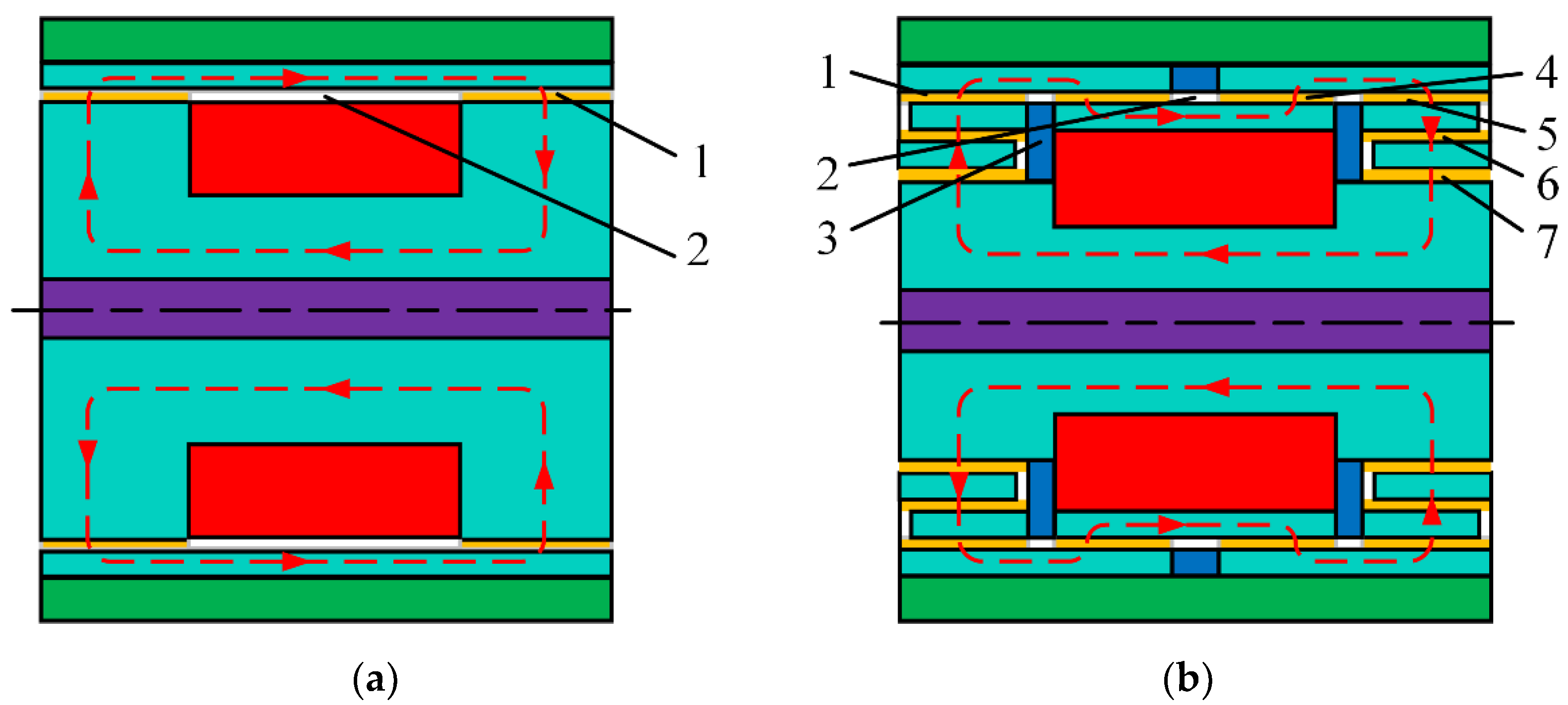
Figure 1. Structural schematic of the MR damper: (a) Traditional MR damper; (b) Proposed MR damper. 1. Magnetic activated region, 2. Non-flux region, 3. Non-magnetic material, 4. Second outer gap, 5. First outer gap, 6. Middle gap, 7. Inner gap.
Actuators 11 00165 g001
Figure 2. Schematic diagram of the MR damper with folded resistance gaps and bending magnetic circuit. 1. Piston rod, 2. End cover, 3. Cylinder, 4. Piston cover, 5. Inner magnetic sleeve, 6. Middle magnetic sleeve, 7. Outer magnetic sleeve. 8, Exciting coil, 9. Non-magnetic ring, 10. Magnetic semicircle, 11. Non-magnetic disk, 12. Magnetic core, 13. End shield.
Actuators 11 00165 g002
Figure 3. Simplified magnetic circuit of the proposed MR damper. 1. Magnetic core, 2. Inner gap, 3. Inner magnetic sleeve, 4. Middle gap, 5. Middle magnetic sleeve, 6. First outer gap, 7. Outer magnetic sleeve, 8. Second outer gap, 9. Non-magnetic ring.
Actuators 11 00165 g003
Figure 4. The performance curves of MR fluids: (a) B-H curve; (b) τB curve.
Actuators 11 00165 g004
Figure 5. Axisymmetric model for the FEA: (a) Proposed MR damper; (b) Traditional MR damper.
Actuators 11 00165 g005
Figure 6. Comparison of the magnetic flux lines: (a) Proposed MR damper; (b) Traditional MR damper.
Actuators 11 00165 g006
Figure 7. Contours of the magnetic flux density of the both MR damper: (a) Proposed MR damper; (b) Traditional MR damper.
Actuators 11 00165 g007
Figure 8. The comparison of the magnetic flux density between the proposed MR damper and the traditional MR damper.
Actuators 11 00165 g008
Figure 9. Magnetic flux density of the proposed MR damper at each gap with various current inputs: (a) Inner gap and middle gap; (b) First outer gap and Second outer gap.
Actuators 11 00165 g009
Figure 10. Average magnetic flux density with different applied current inputs.
Actuators 11 00165 g010
Figure 11. Comparison of the damping force of the traditional damper and the proposed damper under different applied currents.
Actuators 11 00165 g011
Figure 12. Proposed MR damper with folded resistance gaps and bending magnetic circuit: (a) Components; (b) Prototype.
Actuators 11 00165 g012
Figure 13. Experimental test rig of MR damper: 1. Vibration excitation platform, 2. proposed MR damper, 3. controlled computer, 4. DC power supply, 5. electro-hydraulic servo controller.
Actuators 11 00165 g013
Figure 14. Damping force under different amplitudes and frequencies: (a) Damping force under different amplitudes; (b) Damping force under different frequencies.
Actuators 11 00165 g014
Figure 15. Damping force under different frequencies with the current of 1 A and the amplitude of 10 mm: (a) Damping force vs. displacement; (b) Damping force vs. velocity.
Actuators 11 00165 g015
Figure 16. Damping force under different applied currents.
Actuators 11 00165 g016
Figure 17. Simulated and experimental damping force under different applied currents.
Actuators 11 00165 g017
Figure 18. Comparison of the damping performance between the proposed and the traditional MR damper: (a) Damping force versus current; (b) Dynamic range versus current.
Actuators 11 00165 g018
Table 1. Main structural dimensions of the proposed MR damper.
ParameterValue (mm)ParameterValue (mm)
Inside radius of piston rod (ro)7Length of first outer gap (L1)8
External radius of core (rc)13Length of second outer gap (L2)7
Radius of piston (rp)31Length of non-magnetic ring (ta)13
Radius of inner gap (ri)19Thickness of non-magnetic disk (tb)3
External radius of piston rod (rd)10Thickness of sleeve (tc)3
Thickness of gap (g)1Height of exciting coil (Hc)11
Table 2. Comparison of the damping force per unit volume of the proposed MR damper with other MR dampers.
MR DamperRadius of Piston (mm)Maximum Positive Damping Force (N)Damping Force Per Unit Volume (kN/m3)Dynamic Range
Traditional MR damper3127892.4 × 10411.8
MR damper in
Reference [32]
35.754862.92 × 1047
Proposed MR damper3143462.93 × 10419.3
Publisher’s Note: MDPI stays neutral with regard to jurisdictional claims in published maps and institutional affiliations.