Article

Design of a Panoramic Scanning Device Based on a Piezoelectric Ceramic Stack Actuator and Friction Transmission

1
School of Instrumentation and Optoelectronic Engineering, Beihang University, Beijing 100191, China
2
Institute of Unmanned System, Beihang University, Beijing 100191, China
*
Author to whom correspondence should be addressed.
Actuators 2022, 11(6), 159; https://doi.org/10.3390/act11060159
Submission received: 10 May 2022 / Revised: 7 June 2022 / Accepted: 10 June 2022 / Published: 13 June 2022
(This article belongs to the Section Miniaturized and Micro Actuators)

Abstract

:
In view of the complex structure and inaccurate positioning capabilities of the existing panoramic scanning system, a panoramic scanning device based on a piezoelectric ceramic stack actuator and friction transmission was designed. In our model, the output displacement of the piezoelectric ceramics is amplified by a bridge-type flexure hinge and applied to a shaft by friction to achieve panoramic scanning imaging. The mathematical model of the device was established, and the working characteristics were analyzed. The analysis demonstrated that the linear displacement increment of the shaft is a superposition. A modality simulation was performed, and the simulation results show that the designed device works normally at a frequency of 511.5 Hz. The test results indicated that the displacement of the actuator can reach 6 μm at an input voltage of 100 V. Moreover, the laser scanning results showed that the designed device can perform panoramic scanning imaging, which meets the requirements for use on the high-speed imaging system.

1. Introduction

The panoramic scanning imaging system can obtain a clear 360° image of the surrounding environment and has the advantages of a large range, a short scanning period, and fast panoramic imaging [1]. As a consequence, it is widely used in security monitoring [2], robot vision [3], oblique photography [4], and laser scanning systems [5]. With the continuous increase in applications, various improvements have been suggested for the panoramic scanning imaging system, such as fine angle control and faster response speed. To meet the new requirements, further research into the panoramic imaging system is necessary.
The panoramic scanning imaging system has attracted widespread attention, and scholars have carried out extensive research. Barth et al. [6] reported a new system that can acquire panoramic images quickly using the camera panning technique. The purpose of this work was to enable a mobile robot to achieve a complete 360° observation of the surrounding environment, so as to smoothly perform navigation tasks. Karaca et al. [7] proposed a novel panoramic stereo hyperspectral imaging system consisting of two line-scan hyperspectral cameras and a rotary stage. The system was utilizable for change detection, target detection, and classification applications. Kerbyson et al. [8] described a new class of high-resolution electro-optical imaging search and surveillance system, which provided an uninterrupted imaging display of the entire 360° panorama. Godber et al. [9] proposed a panoramic scanning system that provides details regarding images with the line-scan sensor by rotating the device relative to an object space. Li et al. [10] presented a panoramic stereo imaging system that uses a single camera coaxially combined with a fisheye lens and a convex mirror. It provided stereo vision over a full 360° horizontal field of view. The aforementioned studies all utilized the rotation method to achieve panoramic scanning imaging. The systems contain one or more lens, and rotation is produced by a motor drive. The motor drive mode created issues in terms of high-resolution, precise control and increasing the size of the system. In addition, this method also occupies a large amount of running memory, which poses a challenge to real-time performance. Various scholars proposed a system that uses multiple lens combinations. Therein, the panoramic image is obtained by stitching together a single lens image. For instance, Wang et al. [11] presented a panoramic annular lens (PAL) system that consists of a panoramic head block unit and six lenses. There are also certain algorithmic studies focused on image stitching [12], which, of course, belong to the subsequent signal processing steps. Moreover, Song et al. [13] developed a 360° panoramic and high-performance system based on two tiled imaging channels with a field of view of 190°. Obviously, this method requires a larger size and a more complex structure as compared to the rotary imaging method.
Various related studies [14] demonstrate that piezoelectric motors are simple in structure and possess fine positioning capabilities, so they are particularly suitable for miniaturization. Higuchi et al. [15] introduced a driving method suitable for a micro-mechanism that utilizes the inertial force caused by rapid deformations of piezoelectric elements. Yao et al. [16] fabricated a small, hollow, multilayer actuator with a diameter of 3 mm from piezoelectric hard lead zirconate titanate (PZT) ceramics using the stacking method. The high-power vibration level at a given sinusoidal drive voltage was significantly enhanced using a multilayer structure under either a non-resonance or a resonance condition. Kim et al. [17] developed a hybrid linear motor that produces high resolution and can travel long distances using the inchworm motion principle. It consists of one push and two clamping devices. Wischnewski et al. [18] introduced a new type of piezoelectric motor in which a hard-type piezoelectric bulk ceramic is modified in order to produce static deflections in the nanometer range by applying a DC voltage and ultrasonic oscillatory continuous movements. This is able to reach high speeds in resonance drive mode. Furthermore, Dubois et al. [19] discussed parasitic vibrations coupled with the piezoelectric inertia drive motors system. The focus of his research was to understand how these vibrations are created, propagate, and interact. The micro-displacement of piezoelectric ceramics can be amplified by the bridge-type amplifier [20,21]. Moreover, displacement accumulation can be realized by stepping [22,23]. Inspired by those ideas, a panoramic scanning device based on a piezoelectric ceramic stack actuator and friction transmission was developed. It is able to perform panoramic scanning of the surrounding environment. By adjusting the polarity of the applied voltage, the scanning direction and velocity of the imaging device can be controlled. The proposed device has the advantages of a compact structure, accurate positioning ability, and easy miniaturization.
This article is arranged as follows: Section 1 is the introduction. Section 2 presents the overall design of the proposed panoramic scanning device. The mathematical models are described in Section 3. The dynamic simulation, the modality simulation, and extension estimation are detailed in Section 4. The experiments are explored and the discussion is presented in Section 5. Finally, the conclusions are drawn in Section 6.

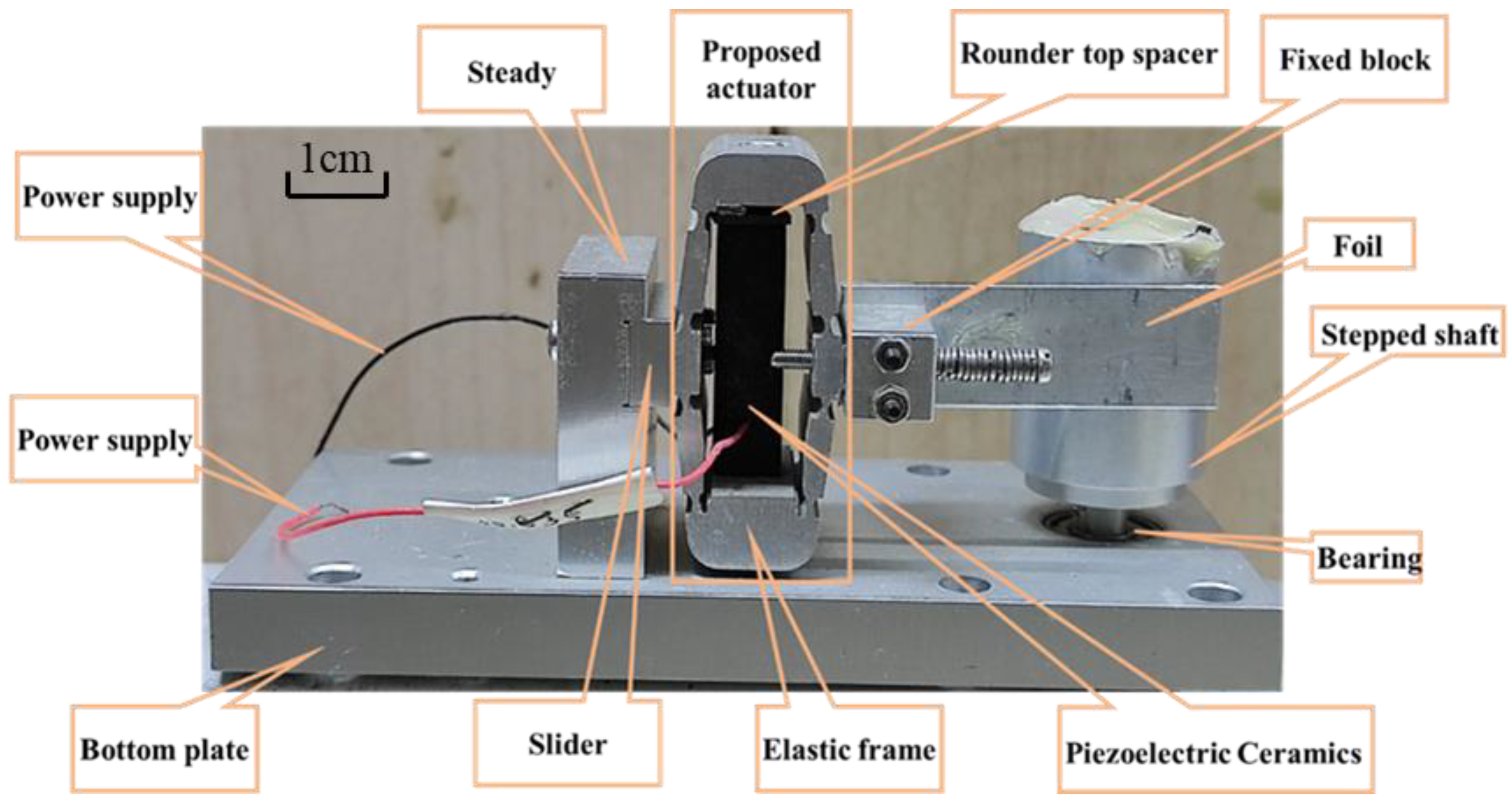
2. Overall Design of the Proposed Panoramic Scanning Device

The panoramic scanning device based on a piezoelectric ceramic actuator proposed in this paper is shown in Figure 1. It can be seen in Figure 1 that the proposed device consists of a bottom plate, a steady, a slider, the proposed actuator, a fixed block, a foil, and a stepped shaft. In addition, the proposed actuator consists of an elastic frame, a rounder top spacer, and piezoelectric ceramics.
There are four standard screw holes around the bottom plate for fixing to the optical platform. There are two screw holes on the bottom of the steady and two counterbore holes on the bottom of the bottom plate. They are connected by screws. A through groove is provided at the right end of the steady. A fixed block, an elastic frame, and a slide are locked by screws. The foil is locked by two fixed blocks and the closeness to the stepped shaft can be adjusted by moving the slider. The stepped shaft is fixed onto the bottom plate through the bearing. The piezoelectric ceramics and rounder top spacers are fixed in the elastic frame.

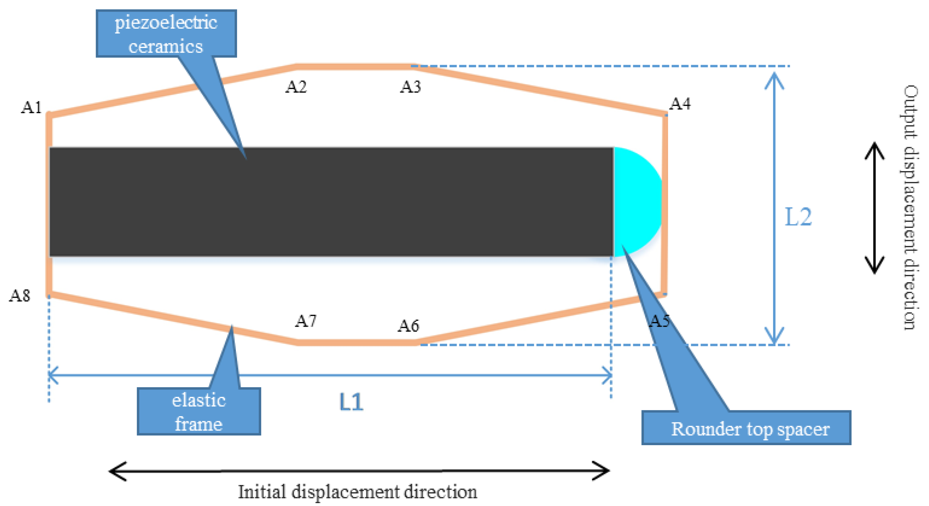
3. Mathematical Models

When the proposed device is working, the reflector is mounted on the stepped shaft. When the piezoelectric ceramic is energized, it produces a small amount of displacement in the L1 direction, which is shown in Figure 2. Then, it is amplified by the elastic frame in the L2 direction. As a consequence, the foil creates displacement and forces the stepped shaft to rotate due to friction.
The actuator consists of the elastic frame, the piezoelectric ceramics, and the rounder top spacer. It can be seen in Figure 2 that the elastic frame is represented as a yellow line, and its eight vertices are recorded as A1–A8. The piezoelectric ceramics is a black rectangular with a length of L1, and the rounder top spacer is a blue semicircle. Let ∠A1A2A3 = ∠A8A7A6 = ∠A7A6A5 = ∠A2A3A4 = θ ; when a certain voltage is applied to the piezoelectric ceramic and the initial displacement Δ L 1 occurs in the transverse direction (the L1 direction), the longitudinal amplification displacement (the L2 direction) can be expressed as follows:
Δ L 2 Δ L 1 / tan θ
1 / tan θ is recognized as the amplification ratio of the elastic frame. Considering that the displacement generated by the piezoelectric ceramics is small after being electrified, in order to achieve large angle deflection, a large displacement is required. Therefore, the amplification ratio of the elastic frame must be as large as possible, and usually θ is greater than 170°. Moreover, the initial displacement is related to the stiffness of the elastic frame, which can be expressed by Formula (2):
Δ L 1 = Δ L 0 k y / ( k y + k l )
where Δ L 0 is the extension of the actuator without voltage, k y is the stiffness of the piezoelectric ceramics, and k l is the stiffness of the elastic frame in the initial displacement direction.
After the actuator outputs the displacement, the foil drives the shaft to rotate through the friction force. Three different situations occur:
➀ The shaft starts to rotate.
The displacement of the foil is greater than the linear displacement of the shaft. At this time, there is sliding friction between foil and the shaft, and its magnitude is a fixed value:
μ D F N R = F s R + M
where μ D is the dynamic friction coefficient between foil and shaft, F N is the pressure between foil and shaft, F s is the maximum static friction between foil and the shaft, R is the radius of the shaft, and M is the moment of inertia of the shaft.
The dynamic friction between the bearing and shaft can be expressed as follows:
F b f = μ b d F N
where μ b d is the dynamic friction coefficient of the bearing.
Once the shaft has rotated, Formula (5) is established.
F b f R b < F f R
where R and R b are the radii of the shaft and bearing, respectively, and F f is the sliding friction between the foil and the shaft.
Assuming that the output force of the actuator is F A , it is obvious that:
F A > F f = μ D F N
Then, it can be determined that the dynamic friction coefficient between the foil and the shaft satisfies the following relationship:
μ D < F A / F N
➁ The foil and the shaft are relatively stationary.
The displacement of the foil is equal to the linear displacement of the shaft, and there is no relative slip between them. There is static friction between them, and its magnitude is smaller than the maximum static friction force:
μ b d F N R b = F N μ D R < μ s F N R
where μ s is static friction coefficient between the foil and shaft. Meanwhile, Formula (9) is satisfied:
μ s F N R > F A R > μ b d F N R b
Therefore, we can obtain the following:
μ s > F A / F N > μ b d R b / R
➂ The foil begins to move back.
There is still relative movement between the foil and shaft, but their movement directions are opposite. As a consequence, there is the following relationship:
F N R μ D + F N μ b d R b = J w ˙
where J is the rotational inertia of the shaft, and J is the angular acceleration of the shaft.
According to the above three cases, the linear displacement increment of the shaft is approximated as a straight line, and its variety is shown in Figure 3.
It can be seen in Figure 3 that the linear displacement increment mode of the shaft is the inertia superposition. When the applied triangular wave voltage (U) is increased, the shaft accelerates to rotate, and its linear displacement (S) increases rapidly; when the applied triangular wave voltage (U) is decreased, its linear displacement (S) increases slowly. By adjusting the duty cycle of the applied triangle wave voltage (U), i.e., increasing the time of rising and reducing the time of dropping, the shaft can be rotated in one direction all the time, thereby realizing scanning imaging. When there is external vibration interference, which can be measured by other sensors, stability can be achieved by changing the applied voltage so that the rotation variety of the shaft and the interference are mutually offset.

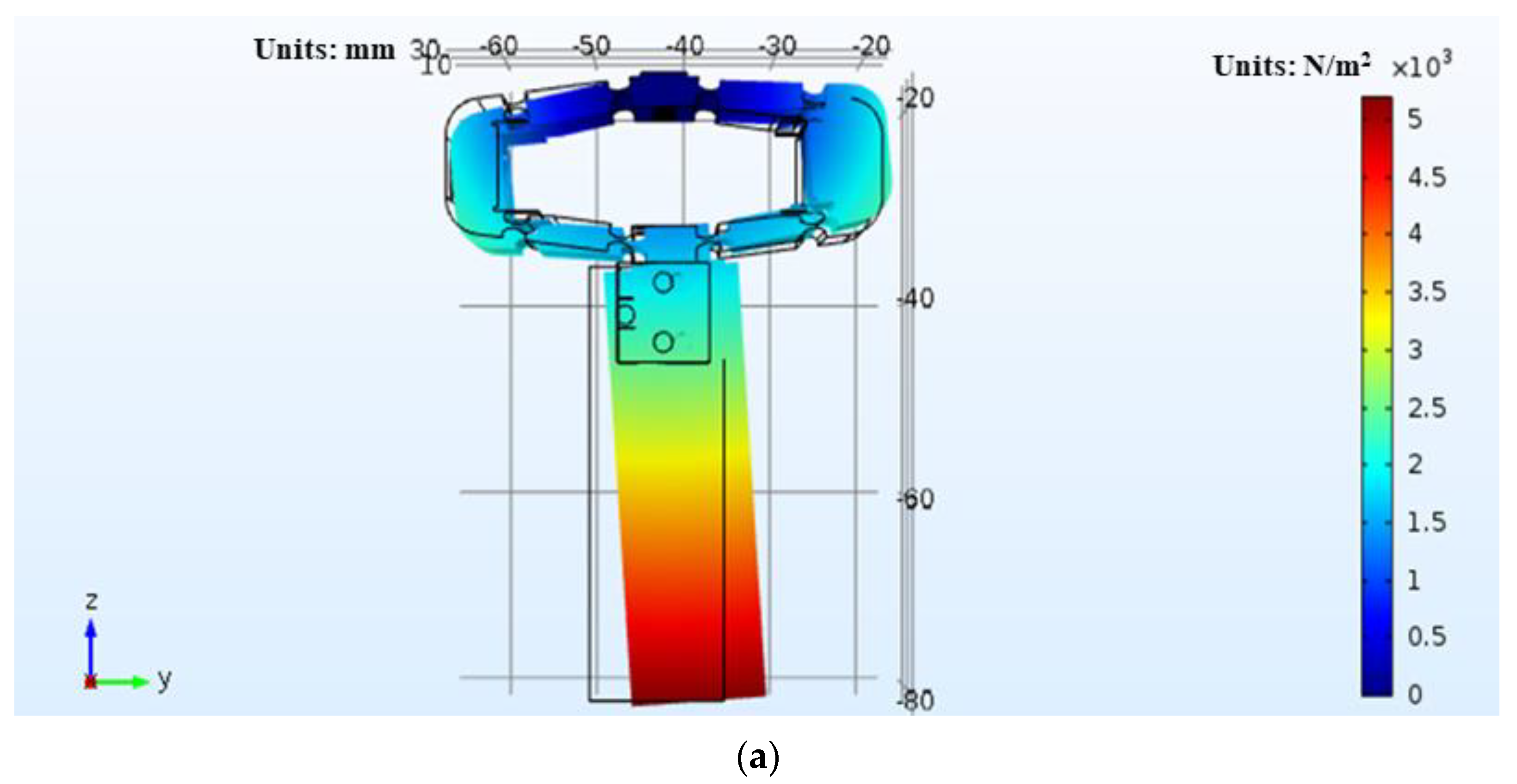
4. Simulation Analysis

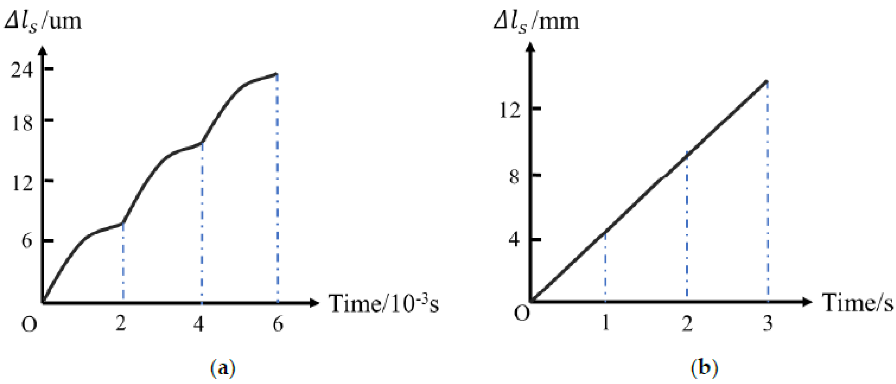
4.1. Extension Simulation and Estimation

For different θ, under the conditions of k y = 50   N / μ m , k l = 5.7498   Nm / rad , and Δ L 0 = 16   μ m , we performed a finite element simulation on the extension of the actuator. The length of the linkage A1A2 was 15 mm. The force applied to the inner sides of both ends of the elastic frame (the same direction as L1) during simulation was equal to k y ( Δ L 0 Δ L 1 ) , where Δ L 0 was obtained from the simulation results. Moreover, we used Formulas (1) and (2) to theoretically estimate the extension of the actuator. The results of the simulation and theoretical estimation are shown in Table 1.
As can be seen in Table 1, the relative error between the simulation and theoretical estimation results was less than 15% when θ ≤ 174°. When θ ≥ 176°, the four arms (A1A2, A3A4, A5A6, and A7A8) of the elastic frame were almost parallel. The vertical displacement of A2A3 at the upper end of the elastic frame caused larger changes in θ and the displacement amplification ratio of the elastic frame. Therefore, the estimated extension error according to Equations (1) and (2) varied with the angle increase and increased significantly. According to the simulation results, the final designed θ is equal to 173°. The key parameters of the developed device are summarized in Table 2. The specifics of the piezoelectric ceramics used in this article are listed in Table 3.

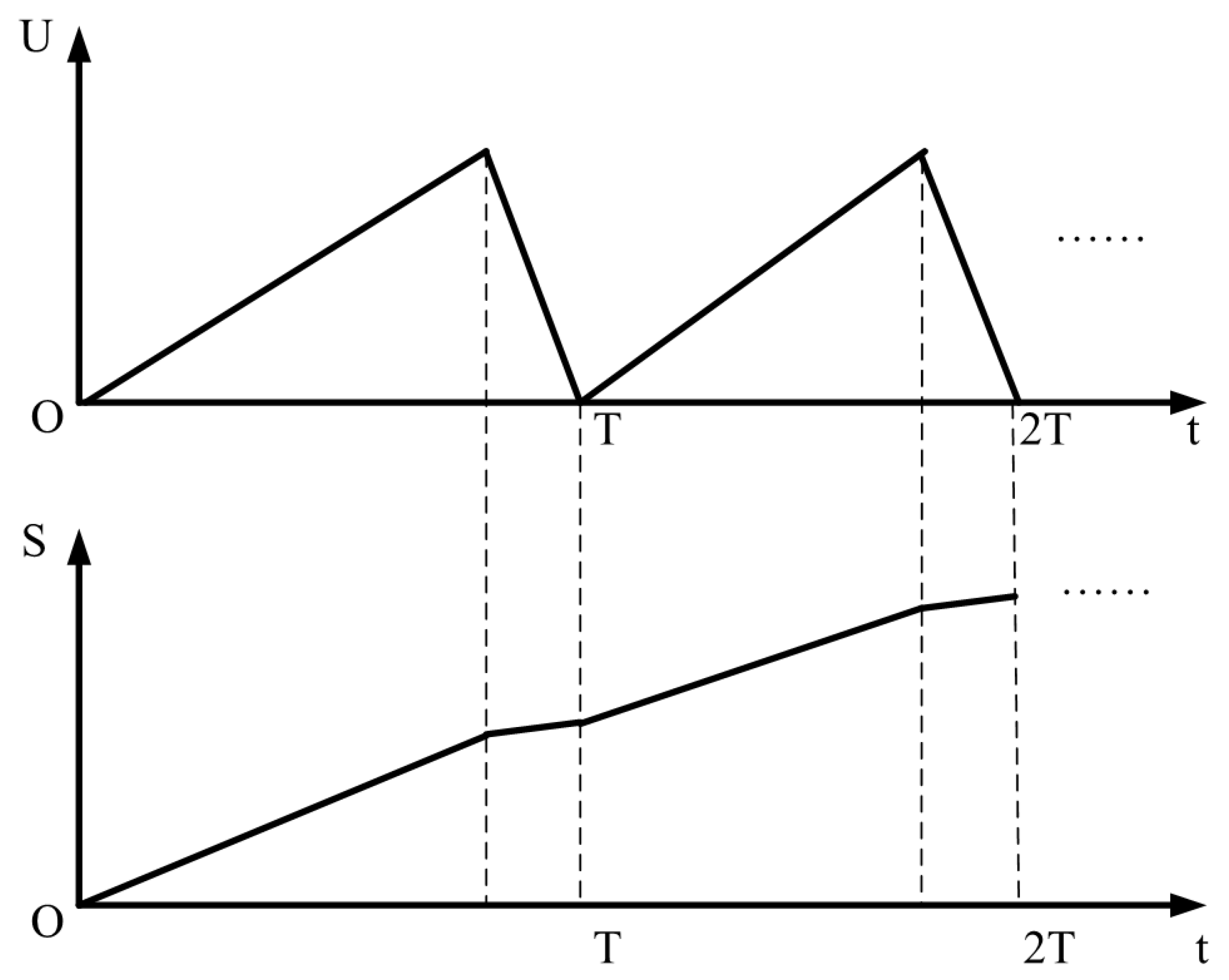
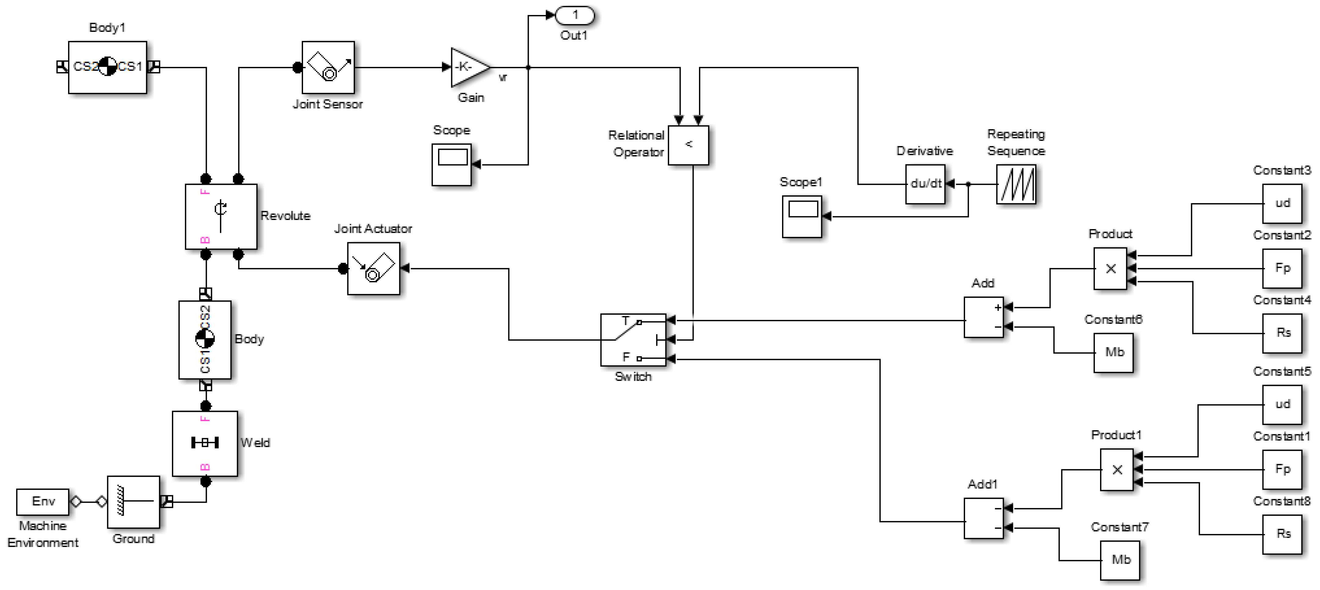
4.2. Dynamic Simulation

In order to verify the feasibility of the proposed panoramic scanning imaging actuator, to understand the working principle of each part, to explore the influence of each parameter on the working state of the entire device, and to establish the optimal parameter matching value, SimMechanics Part in MATLAB was adopted to model and analyze the proposed mechanical device. The model diagram is shown in Figure 4.
As analyzed in Section 3, the motion state of the foil can be divided into three types. However, for friction, only two types are of relevance: sliding friction and static friction. The left side of Figure 4 shows a simplified model of the device, including the connections between the various modules and the coordinates relative to the earth coordinate system, which were obtained using the size of the designed device.
On the right side of Figure 4, the signal input terminal and two parameter input terminals are shown, which represent sliding friction and static friction, respectively. A selector and output terminal are set in the middle, and the pressure between the foil and shaft and the radius of the shaft were adjusted to observe the output of the device.
In the process of establishing the Simulink model, the actual model was abstracted and simplified as follows:
(1)
While ignoring the nonlinear characteristics of piezoelectric ceramics and elastic frame itself, the designed actuator is considered to be an ideal displacement actuator;
(2)
The dynamic and static friction coefficients between the foil and the shaft are equal;
(3)
The friction torque of the bearing is constant;
(4)
Each parameter is independent.
The relationship between the radius and the linear velocity of the shaft is shown in Equation (12):
V L = k 1 R
Furthermore, the relationship between the pressure between the foil and shaft and the linear velocity of the shaft is summarized in Equation (13):
V L = { k 2 [ ( F N - F S ) R - M ]   F N R F s R + M   0 F N R F s R + M
where V L denotes the linear velocity of the shaft; F S denotes the maximum static friction; F N represents the pressure between the shaft and foil; R is the radius of the shaft, k 2 and k 1 are the linear coefficients, respectively; and M is the moment of inertia of the shaft.
On the basis of Equation (12), it can be seen that the linear velocity of the shaft increases with the radius of the shaft. Obviously, the larger the radius, the larger the friction torque provided by the foil. Under the condition of constant resistance torque, the linear velocity increased with the increasing torque. The simulation results are consistent with the principle. In practical applications, the linear velocity can be adjusted by appropriately adjusting the radius of the shaft; however, as a result of the constraints of installation space and the moment of inertia, the radius of the shaft should not be too large.
Equation (13) shows the relationship between the pressure between the foil and shaft and the linear velocity of the shaft. The pressure between the foil and shaft directly affects the friction force, thereby changing the friction torque. When the torque provided by the foil is greater than the sum of the inertia torque and the maximum static friction torque of the shaft, the shaft starts to rotate, which is consistent with the model analysis.

4.3. Modality Simulation

The vibration state of the proposed device is also related to the input frequency, so the modality analysis of the actuator was carried out using COMSOL. Various vibration modes under different frequencies were explored, and the results are shown in Figure 5.
According to Figure 5a, when the frequency is low (f = 245.42 Hz), the actuator swings up and down, which does not meet the expected vibration form. However, this form of vibration is more likely to occur. Figure 5b shows that, when the frequency is moderate (f = 511.49 Hz), the actuator pushes forward and pulls back, which is consistent with the expected motion form. In Figure 5c, it can be seen that when the frequency is high (f = 603.3 Hz), the actuator moves left and right; i.e., it deviates from the original intention and the produced form is not the expected form of vibration. Therefore, it is necessary to avoid inputting an overly high frequency.
Through the modality analysis of the actuator, it is possible to understand the various vibration forms at different frequencies. Therefore, it was possible determine that the frequency for normal operation is approximately 511 Hz.

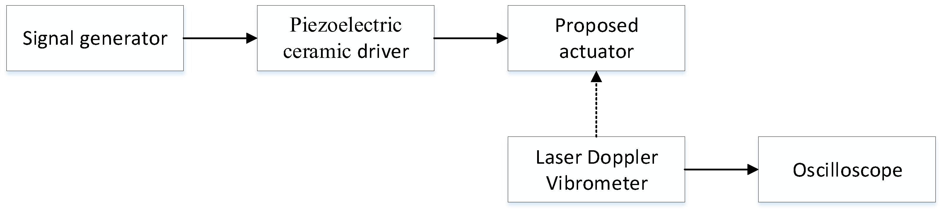
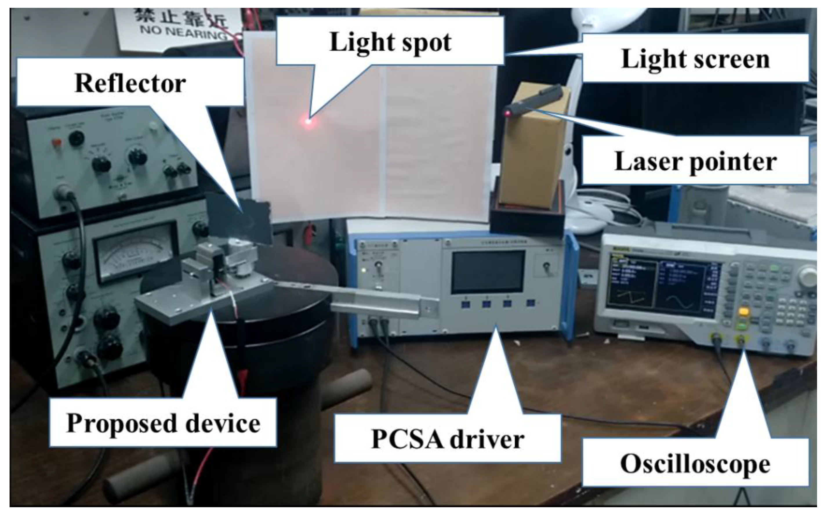
5. Experiment and Discussion

In order to verify the working principle and characteristic analysis results, a characteristic test system was designed based on the aforementioned analysis and simulation. The schematic diagram is shown in Figure 6.
It can be seen in Figure 6 that the test system consists of a signal generator, a piezoelectric ceramics driver, a laser Doppler vibrometer, an oscilloscope, and the proposed actuator. After the driving signal generated by the signal generator is amplified by the piezoelectric ceramic driver, the proposed actuator is forced to extend. The elongation was measured by the laser Doppler vibrometer, and the results were displayed on the oscilloscope (the dotted line in Figure 8 represents no actual contact).
Under the voltage drive of the triangle wave signal of 500 Hz and 100 V, the relationship between the extension of the actuator and time is shown in Figure 7a, and the relationship between the extension of the actuator and voltage is presented in Figure 7b.
As is shown in Figure 7a, the maximum extension at this time was approximately 6 μm. By increasing the drive voltage, Δ L 2 could be further increased. It can be seen in Figure 7b that there was an obvious hysteresis loop, which reduces the accuracy of the proposed actuator. It can be seen that the working mode of the actuator is consistent with the theoretical analysis.
In order to verify that the device designed in this study is able to achieve panoramic scanning imaging, a laser scanning test was carried out. The test system was set up as shown in Figure 8.
It can be seen in Figure 8 that a reflecting mirror was installed on the rotating shaft of the proposed device; the light spot emitted by the laser pointer was reflected by the mirror and hit the light screen. During the test, a triangle wave signal was input, and the light spot moved with the rotation of the shaft. By regulating the positive and negative attributes of the voltage, the light spot could be scanned clockwise or counterclockwise. By adjusting the frequency and duty cycle of the signal, the scanning velocity could be controlled. The relationship curve between the linear displacement of the shaft and time is shown in Figure 9.
Figure 9a,b shows the linear displacement curves of the stepped shaft within three periods and 3 s, respectively, where Δ l s represents the linear displacement of the stepped shaft. As can be seen in Figure 9b, the linear displacement of the stepped shaft accumulated approximately 14 mm within 3 s. The linear displacement accumulation curve is approximately a straight line. The linear displacement value per second is marginally different. This demonstrates that the rotation of the stepped shaft was not uniform, which is confirmed in Figure 9a. It can be seen in Figure 9a that the accumulation of linear displacement was fast and then slow, which accurately corresponds to the forward and backward processes of the foil. The experimental results verify the accuracy of the theoretical analysis. The linear displacement increment of each cycle was also different. This may have been affected by vibrations or other factors. In response to this phenomenon, we carried out velocity matching experiments. The experimental setup is shown in Figure 10.
As is shown in Figure 10, the proposed device was fixed onto the electric turntable to ensure that the rotation axis of the proposed device coincided with the rotation axis of the electric turntable. During the test, a triangular wave signal was input, and the rotation velocity of the reflector was chosen to coincide with that of the electric turntable, but in the opposite direction, by adjusting the signal frequency and duty cycle. The purpose was to maintain the light point in a stationary position on the light screen. However, as can be seen in the test video, the light spot moved in a small range, which may have been caused by environmental vibrations or hysteresis. In the future, linear control feedback algorithms will be adopted to improve stability. A link to the test video can be found in the “Supplementary Materials” section.

6. Conclusions

The existing panoramic scanning system has a complex structure and inaccurate positioning capabilities. In this paper, a panoramic scanning device based on piezoelectric actuators was designed. It is able to perform panoramic scanning using a piezoelectric ceramic stack actuator with small displacement and friction transmission.
The modality analysis showed that the working mode of the proposed device worked as expected when the frequency was approximately 500 Hz. The laser scanning test results indicated that the device can achieve panoramic scanning. When the thickness of the foil was 0.5 mm, it took approximately 16.75 s to perform one revolution. In addition, the extension of the foil was approximately 6 um in each cycle. The simulation and experiment verified the rationale of the design.
However, as a result of the influences of vibration and other factors, the linear displacement of the shaft was different in each cycle. Moreover, the velocity matching test results show that the beam cannot remain stable without intervention. In the future, a closed-loop feedback control will be introduced to improve the performance of the current system.

7. Patents

The authors of this article applied for an invention patent, named “An optical axis stabilized platform,” and it was authorized. The authorized publication number is CN107176306B.

Supplementary Materials

The test video can be obtained from following link: https://drive.google.com/file/d/1lbM1kbzEb_NzrnU579Q4WdgicA6mGuo6/view?usp=sharing. (accessed on 1 May 2022).

Author Contributions

Conceptualization, M.D.; methodology, M.D. and H.D.; software, M.D.; validation, M.D. and H.D.; formal analysis, M.D.; investigation, Y.Z. and C.H.; resources, M.W.; data curation, M.D. and H.D.; writing—original draft preparation, M.D. and Y.Z.; writing—review and editing, M.W., C.H. and Y.Z.; visualization, M.W. and C.H.; supervision, M.W.; project administration, M.W. All authors have read and agreed to the published version of the manuscript.

Funding

This research received no external funding.

Institutional Review Board Statement

Not applicable.

Informed Consent Statement

Not applicable.

Data Availability Statement

Not applicable.

Conflicts of Interest

The authors declare that they have no known competing financial interests or personal relationships that could have appeared to influence the work reported in this paper.

References

  1. Duke, G.; Tian, G.Y.; Dave, T. Panoramic imaging—A review. Comput. Graph. 2003, 27, 435–445. [Google Scholar]
  2. Tian, D.; Wang, Y.; Wang, Z.; Wang, F.; Gao, H. Long Integral Time Continuous Panorama Scanning Imaging Based on Bilateral Control with Image Motion Compensation. Remote Sens. 2019, 11, 1924. [Google Scholar] [CrossRef] [Green Version]
  3. Yu, J.; Jiang, W.; Luo, Z.; Yang, L. Application of a Vision-Based Single Target on Robot Positioning System. Sensors 2021, 21, 1829. [Google Scholar] [CrossRef] [PubMed]
  4. Zhang, J.; Hu, Q. A Visualization Progress Management Approach of Bridge Construction Based on Mixed Panoramic and Oblique Photogrammetry. In Proceedings of the 2018 26th International Conference on Geoinformatics, Kunming, China, 28–30 June 2018; pp. 1–6. [Google Scholar]
  5. Skormin, V.A.; Busch, T.E.; Givens, M.A. Model reference control of a fast steering mirror of a pointing, acquisition and tracking system for laser communications. In Proceedings of the Aerospace & Electronics Conference, Dayton, OH, USA, 22–26 May 1995. [Google Scholar]
  6. Barth, M.; Barrows, C. A fast panoramic imaging system and intelligent imaging technique for mobile robots. In Proceedings of the International Conference on Intelligent Robots & Systems, Osaka, Japan, 4–8 November 1996. [Google Scholar]
  7. Karaca, A.C.; Erturk, A.; Gullu, M.K.; Erturk, S. A novel panoramic stereo hyperspectral imaging system. In Proceedings of the 2014 6th International Symposium on Communications, Control and Signal Processing (ISCCSP), Athens, Greece, 21–23 May 2014. [Google Scholar]
  8. Kerbyson, G.M. High-Resolution Full-Panoramic Imaging Surveillance System; SPIE—The International Society for Optical Engineering: Orlando, FL, USA, 2002; Volume 4708, pp. 173–183. [Google Scholar]
  9. Godber, S.X.; Petty, R.S.; Robinson, M. Panoramic Line-Scan Imaging System for Teleoperator Control; SPIE the International Society for Optical Engineering: San Jose, CA, USA, 1994. [Google Scholar]
  10. Li, W.; Li, Y.F. Single-camera panoramic stereo imaging system with a fisheye lens and a convex mirror. Opt. Express 2011, 19, 5855–5867. [Google Scholar] [CrossRef] [PubMed]
  11. Wang, J.; Huang, X.; Bai, J.; Wang, K.W.; Hua, Y.X. Design of high resolution panoramic annular lens system. In Proceedings of the SPIE 11338, AOPC 2019: Optical Sensing and Imaging Technology, Beijing, China, 7–9 July 2019; Volume 113382. [Google Scholar]
  12. Zou, X.; Song, H. The fast formation of high-precision panoramic image for the processing of borehole camera video of deep rock mass structures. Bull. Eng. Geol. Environ. 2021, 80, 2199–2213. [Google Scholar] [CrossRef]
  13. Song, W.; Liu, X.; Lu, P.; Huang, Y.; Weng, D.; Zheng, Y.; Liu, Y.; Wang, Y. Design and assessment of a 360° panoramic and high-performance capture system with two tiled catadioptric imaging channels. Appl. Opt. 2018, 57, 3429–3437. [Google Scholar] [CrossRef] [PubMed]
  14. Hunstig, M. Piezoelectric Inertia Motors—A Critical Review of History, Concepts, Design, Applications, and Perspectives. Actuators 2017, 6, 7. [Google Scholar] [CrossRef] [Green Version]
  15. Higuchi, T.; Yamagata, Y.; Furutani, K.; Kudoh, K. Precise positioning mechanism utilizing rapid deformations of piezoelectric elements. In Proceedings of the Micro Electro Mechanical Systems, An Investigation of Micro Structures, Sensors, Actuators, Machines & Robots, Napa Valley, CA, USA, 11–14 February 1990. [Google Scholar]
  16. Yao, K.; Uchino, K.; Xu, Y.; Dong, S.; Lim, L.C. Compact Piezoelectric Stacked Actuators for High Power Applications; IEEE: Piscataway, NJ, USA, 2000; Volume 47, pp. 819–825. [Google Scholar]
  17. Kim, J.; Kim, H.-K.; Choi, S.-B. A hybrid inchworm linear motor. Mechatronics 2002, 12, 525–542. [Google Scholar] [CrossRef]
  18. Wischnewski, M.; Delibas, B.; Wischnewski, A. Piezoelectric motor operated both in resonance and DC modes. In Proceedings of the ACTUATOR International Conference and Exhibition on New Actuator Systems and Applications, Online, 17–19 February 2021; pp. 1–4. [Google Scholar]
  19. Dubois, F.; Belly, C.; Saulot, A.; Berthier, Y. Stick-slip in stepping piezoelectric Inertia Drive Motors—Mechanism impact on a rubbing contact. Tribol. Int. 2016, 100, 371–379. [Google Scholar] [CrossRef]
  20. Claeyssen, F.; Le Letty, R.; Barillot, F.; Sosnicki, O. Amplified Piezoelectric Actuators: Static & Dynamic Applications. Ferroelectrics 2007, 351, 3–14. [Google Scholar]
  21. Gang, Y.; Dai, H.; Shi, D. Single piezoelectric ceramic stack actuator based fast steering mirror with fixed rotation axis and large excursion angle. Sens. Actuators A Phys. 2015, 235, 292–299. [Google Scholar]
  22. Six, M.F.; LeLetty, R.; Coste, P.; Claeyssen, F. Rotating step by step piezomotor for nanopositioning and space applica-tions. In Proceedings of the Actuator 2006: 10th International Conference on New Actuators & 4th International Exhibition on Smart Actuators and Drive Systems, Bremen, Germany, 14–16 June 2006. [Google Scholar]
  23. Claeyssen, F.; Ducamp, A.; Barillot, F.; Le Letty, R.; Porchez, T.; Sosnicki, O.; Belly, C. Stepping piezoelectric actuators based on APAs. In Proceedings of the Actuator 2008: 11th International Conference on New Actuators & 5th International Exhibition on Smart Actuators and Drive Systems, Bremen, Germany, 9–11 June 2008. [Google Scholar]
Figure 1. Overall design of panoramic scanning imaging device.
Actuators 11 00159 g001
Figure 2. Simplified schematic diagram of the actuator.
Actuators 11 00159 g002
Figure 3. The relationship between the linear displacement increment of the shaft and the applied voltage (T is the cycle of the applied triangular wave voltage).
Actuators 11 00159 g003
Figure 4. Simulink model of the proposed panoramic scanning imaging actuator.
Actuators 11 00159 g004
Figure 5. Modality of the actuator at different frequencies. (a) The vibration form of actuator when f = 245.42 Hz. (b) The vibration form of actuator when f = 511.49 Hz. (c) The vibration form of actuator when f = 603.3 Hz.
Actuators 11 00159 g005aActuators 11 00159 g005b
Figure 6. Characteristic test system schematic diagram of the proposed device.
Actuators 11 00159 g006
Figure 7. The test result of the extension of the proposed actuator. (a) The relationship between Δ L 2 and time; (b) the relationship between Δ L 2 and input voltage.
Actuators 11 00159 g007
Figure 8. Laser scanning test system.
Actuators 11 00159 g008
Figure 9. The relationship curve between the linear displacement of the shaft and time. (a) Within three periods; (b) within 3 s.
Actuators 11 00159 g009
Figure 10. The experimental setup of the velocity matching experiment.
Actuators 11 00159 g010
Table 1. Extension simulation and estimation comparison.
θ 170°172°174°176°178°
Δ L 2 (simulation) (μm)44.65.285.684.44
Δ L 2 (estimation) (μm)4.525.286.166.765.54
Table 2. Key parameters of the developed device.
Items (Unit)Values
MaterialAluminum alloy
Length of the linkage A1A2 (mm)11.5
θ (°)173
The thickness of the foil (mm)0.5
Stiffness of the elastic frame kl (N m/rad)5.7498
Rotary inertia of the stepped shaft (kg m2)3.325 × 10⁻⁶
Radius of the upper shaft (mm)12
Table 3. The specific information of the piezoelectric ceramics used in this study.
Items (Unit)Values
CompanySuzhou PANT Piezoelectric Ceramics Co., Ltd., Suzhou, China
ModelPTJ1500707321
Types of piezoelectric ceramicsRectangular piezoelectric ceramic laminated actuator
Dimensions of piezoelectric ceramics (mm3)7 × 7 × 30
Official websitehttp://www.pantpiezo.com/product/3.html
(accessed on 1 June 2022).
Publisher’s Note: MDPI stays neutral with regard to jurisdictional claims in published maps and institutional affiliations.

