
A Review on Thomson Coil Actuators in Fast Mechanical Switching


Abstract
1. Introduction
2. Research Overview
2.1. TCA Principle
2.2. Background

| Reference | DC Breaker Rate | Actuation Characteristics | ||||
|---|---|---|---|---|---|---|
| Time | Speed | Force/Weight | Drive Energy | Stroke | ||
| Polman et al., 2001 [39] | 600 V/6 kA | 1.2 ms | 75 kN/0.8 kg | 6 kA | 6 mm | |
| Steurer et al., 2003 [45] | 12 kV/2 kA | 100–250 μs ** | 20 m/s | 0.05 kg | - | 10 mm |
| Roodenburg, 2005 [48] | 3 kV/7 kA | 422 μs/2 ms * | 31.8 m/s | 100 kN/2 kg | 3.87 kJ 0.86 mF/3 kV | 27 mm |
| Roodenburg, 2008 [52] | 8 kA | 450 μs/2 ms * | 18 m/s | 200 kN/2.7 kg | 1.4–2.75 kJ ** | 28 mm |
| Li W. et al., 2010 [55,56] | - | 20 ms | 6–8 m/s ** | 2–3.5 kN ** | 400 mF 250 V/1.6 kA | 120 mm |
| Yang et al., 2011 [57] | - | 2.5 ms | 8.4 m/s | 80 kN/4.1 kg | 5700 μF/980 V | 18 mm |
| Zheng et al., 2011 [60] | 1.14 kv | 500 µs/2 ms * | - | 5 kN | 10,000 µF 200 V/3000 A | 5 mm |
| Dong E. et al., 2011 [61] | 1.14 kV/600 A | 5.1 ms 4.75 ms 3.25 ms | - | - | 4700 µF/350 V 6800 µF/290 V 10,000 µF/210 V | 6 mm |
| Bissal et al., 2012 [92] | - | 0.6 ms | 12 m/s | 23 kN/3.6 kg | 7 mF/400 V | 7 mm |
| Wen et al., 2015 [71] | 40.5 kV/20 kA | 2.47 ms 2.3 ms | 10 m/s | 50 kN/5 kg | 8.1 mF/780 V 2.5 mF/1.4 kV | 26 mm |
| Peng C. et al., 2015 [88] | 30 kV/630 A | 300 µs/1 ms * | 1.3 m/s | 0.5 kg | 2 mF/300 V | 5 mm |
| Wu et al., 2015 [93] | - | 5–8 ms | 2.2–3.2 m/s ** | 110 kN/3.85 kg | 5 mF/1200 V | 30 mm |
| Yuan et al., 2016 [64] | - | 2.7–4.5 ms ** | - | 250 kN | 2500 µF 1600 V/4000 A | 5–22 mm |
| Hou C. et al., 2016 [70] | - | 2.4 ms | - | 19 kN/2.5 kg | 22,000 µF/400 V | 10 mm |
| Zhang et al., 2016 [94] | 12 kV/31.5 kA 20.6 kV/31.5 kA | 500 μs 2 ms | 5 m/s 1 m/s | 90 kN/7.5 kg | 18 mF 13 kA | 10–12 mm |
| Nanxun Z. et al., 2017 [28] | 10 kV | 3.5 ms 2.6 ms | 3.8 m/s 6.8 m/s | 20 kN/3.09 kg 30 kN/4.30 kg | 5000 A 4300 A | 10 mm |
| Ren et al., 2017 [72] | 40.5 kV | 2.5 ms | 5 m/s | 7.5 kg | 15 mF/650 V | 20 mm |
| Hedayati et al., 2017 [95] | 7 kV/100 A | 1.1–3.7 ms ** | - | 0.14 kg | 5 kA 90–170 V | 3 mm |
| Rodriguez et al., 2017 [85] | 27 kV/200 A | 2 ms | 4 m/s | 0.5 kg | 122 J 1500 μF/425 V | 6–12 mm |
| Stroehla et al., 2019 [24] | 5 A | 3 ms | 7 m/s | 2 kg | - | 10 mm |
| Baudoin et al., 2019 [69] | 24 kV/8 kA | 2.8 ms | 3.8 m/s | 3.5 kg | 30/15 mF 260/325 V | 6 mm |
| Hou Y. et al., 2019 [96] | 12 kV | 5 ms | 3.5–4.8 m/s ** | 50 kN 2–5 kg ** | 250 µ F/3000 V 500 µ F/1250 V | 10–13 mm |
| Zhou Y. et al., 2019 [97] | 110 kV | 1.4 ms 1.8 ms | 20 m/s | 85 kN/6 kg | 6250 J/1 mF/2500 V 6252 J/2 mF/1768 V | 50 mm |
| Guan C. et al., 2020 [98] | 72.5 kV | 2–6 m/s ** | 8 kN | 350–600 V | 28 mm | |
| Zhu et al., 2020 [99] | 110 kV/3000 A | 3 ms | - | 100 kN/7.4 kg | 2.5 mF/7 kA | 22 mm |
3. Structural Composition
3.1. Drive Unit
3.2. Holding Unit
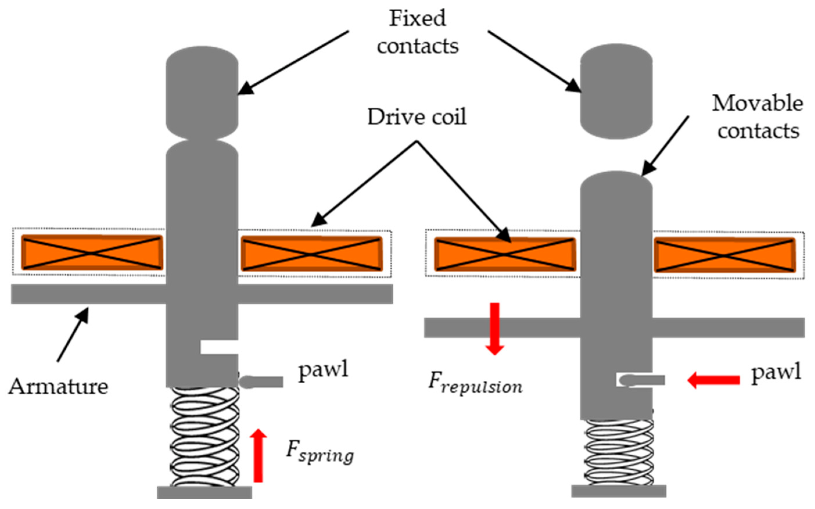
3.2.1. Helical Spring Mechanisms
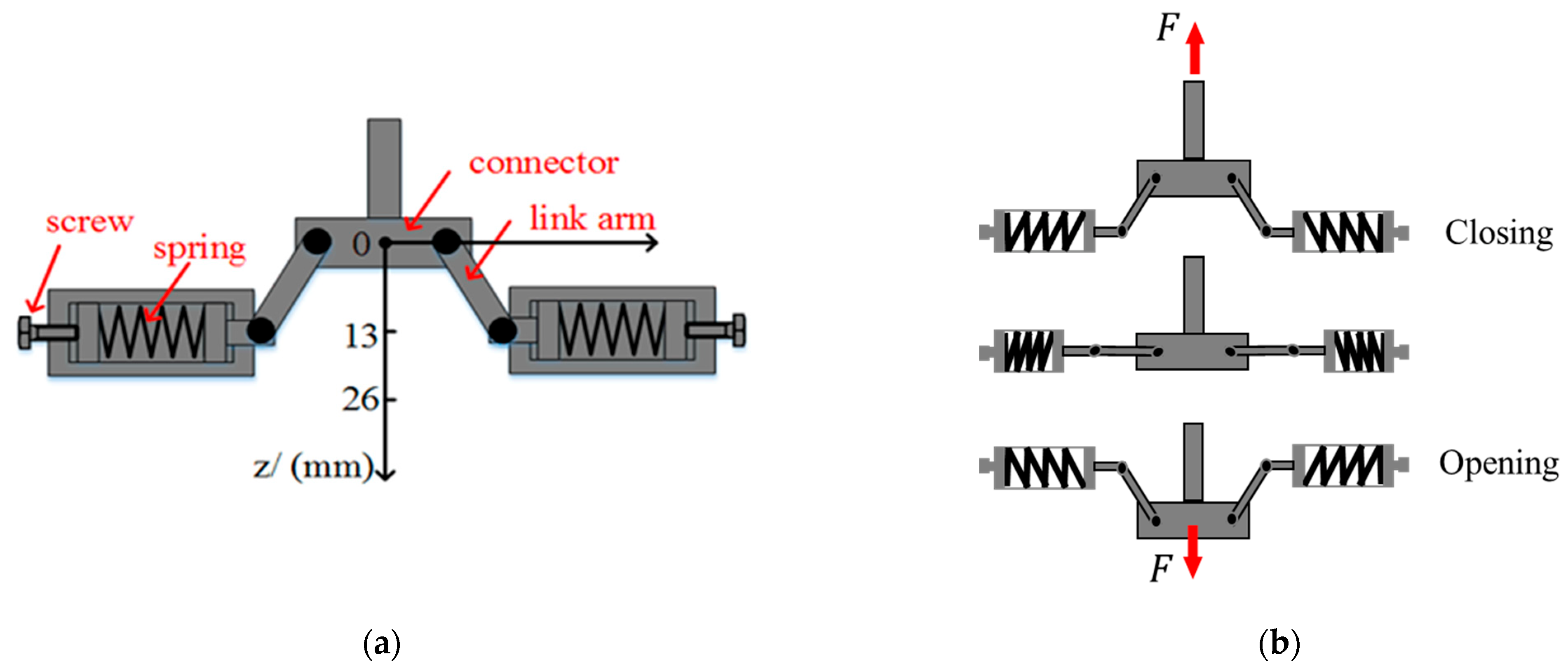
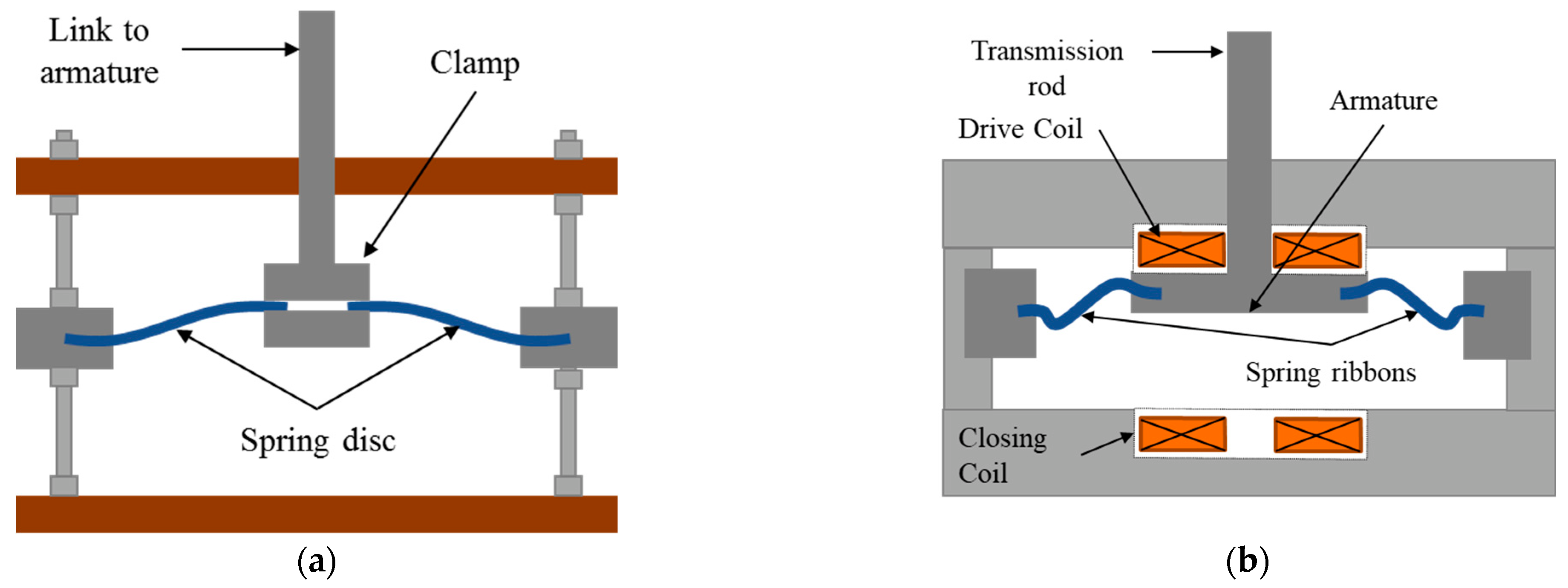
3.2.2. Bi-Stable Spring Mechanism
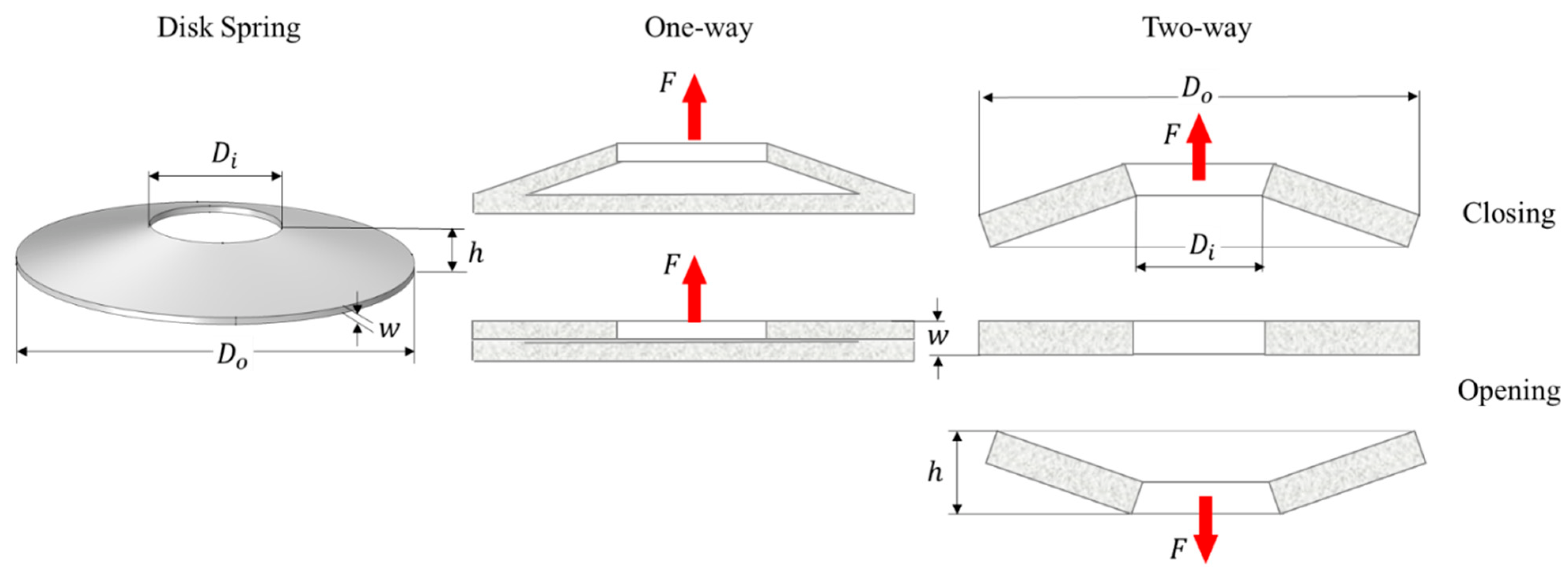
3.2.3. Disc Spring Mechanism
3.2.4. Magnet Holding Mechanism
3.3. Buffer Unit (Damping Mechanism)
3.4. Control Circuit
4. Modeling and Simulation of TCA
4.1. Analytical Analysis
4.2. Numerical Analysis
5. Exploitation of TCA
6. Summary and Conclusions
- The structure size and number of turns of the driving coil. Increasing the coil inductance can increase the induced magnetic field, thus increasing the eddy current of the armature. However, it will reduce the current rise rate, and a relatively optimal value is required. In addition, the magnetic circuit can be improved by increasing the magnetic material, the reasonable design of the coil frame material, optimizing the magnetic field coupling, and improving the driving efficiency.
- The structure size and material of the repulsion disk. When the outer diameter of the armature and the driving coil are the same, the electromagnetic repulsive force is larger and the driving efficiency is higher. Furthermore, the higher the electrical conductivity of the armature material, the greater the induced eddy current, the greater the electromagnetic repulsion force, and the higher the driving efficiency. Considering the skin effect, the driving efficiency could be increased when the thickness of the repulsion plate is twice the corresponding skin depth at a certain discharge frequency of the coil. Considering the armature type, the driving efficiency of the coil–coil type repulsive force mechanism is about twice that of the coil–disk type, but the moving mass is larger. The coil–coil type repulsive force mechanism is suitable when the load mass is large.
- The initial gap between the coil and the disk. A smaller initial coil–armature gap will result in a greater repulsive force and higher drive efficiency.
- The capacitance of the energy storage capacitor. A TCA is highly sensitive to the chosen capacitance and charging voltage. For a particular geometry, load, and material, there exists an optimum capacitance and charging voltage. Studies indicate that a larger voltage and smaller capacitance result in a higher current peak and speed, which are better in terms of force and speed. When the capacitance value of the capacitor is large, the pulse width of the current and the repulsive force is large. However, the rising rate became smaller with a slower initial acceleration, and the other way around. Thus, a trade-off needs to be optimized.
- Efficiency improvement.At present, the driving efficiency of the TCA is very low. The highest theoretically calculated efficiency that could be achieved in a Thomson coil was of 54%, which does not meet the economic requirements of the future DC grids. There is still much work that could be performed by promoting research on improving the driving characteristics, reducing the capacity of the energy storage power supply, and forming a driving efficiency optimization design method.
- Buffering and holding mechanisms.A TCA has a short response time and a fast initial movement speed. The research could be focused on the development of the buffer and holding devices that better match the output characteristics of the repulsion mechanism. This is to enhance buffering and holding effects while ensuring the rapidity of the overall mechanism.
- Mechanical transmission structure.A TCA has a very large repulsion peak during the driving process and a short duration, which brings a great mechanical load to the transmission structure and puts forward great requirements on the structural strength while reducing the motion quality and ensuring the rapidity of the action. It is of great significance to improve the reliability of a TCA and even the overall reliability of the DC circuit breaker by analyzing the impact stress in the operation process and designing an efficient and reliable transmission system. Analyzing the influence of the impact force on the transmission rod and optimizing the structure of the key weak components are the research focus of studying the impact stress of the transmission system and improving the mechanical life.
- Stroke feasibility.A TCA basically relies on inertia in the later stage of the movement and is mostly used in short-stroke drives. Utilizing the rapidity of the repulsion mechanism for higher voltage levels’ and larger strokes’ requirements is of great significance to the application of a TCA to a wider switchgear application.
Author Contributions
Funding
Data Availability Statement
Acknowledgments
Conflicts of Interest
Appendix A. Equivalent Circuit Model (ECM)


Appendix B. Finite Element Method (FEM)

References
- Saeedifard, M.; Graovac, M.; Dias, R.F.; Iravani, R. DC power systems: Challenges and opportunities. In Proceedings of the IEEE PES General Meeting, Minneapolis, MN, USA, 25 July 2010; pp. 1–7. [Google Scholar]
- Li, G.; Balasubramaniam, S.; Tibin, J.; Ugalde-Loo, C.E.; Khadijat, F.J. Frontiers of DC circuit breakers in HVDC and MVDC systems. In Proceedings of the 2017 IEEE Conference on Energy Internet and Energy System Integration (EI2), Beijing, China, 26–28 November 2017. [Google Scholar]
- Bayati, N.; Hajizadeh, A.; Soltani, M. Protection in DC microgrids: A comparative review. IET Smart Grid. 2018, 1, 66–75. [Google Scholar] [CrossRef]
- Mohammadi, F.; Rouzbehi, K.; Hajian, M.; Niayesh, K.; Gharehpetian, G.B.; Saad, H.; Ali, M.H.; Sood, V.K. HVDC Circuit Breakers: A Comprehensive Review. IEEE Trans. Power Electron. 2021, 36, 13726–13739. [Google Scholar] [CrossRef]
- Bini, R.; Backman, M.; Hassanpoor, A. Interruption technologies for HVDC transmission: State-of-art and outlook. In Proceedings of the 4th International Conference on Electric Power Equipment-Switching Technology (ICEPE-ST), Xi’an, China, 22–25 October 2017. [Google Scholar]
- Christian, M.F. HVDC Circuit Breakers: A Review Identifying Future Research Needs. IEEE Trans. Power Del. 2011, 26, 998–1007. [Google Scholar]
- Pei, X.; Cwikowski, O.; Vilchis-Rodriguez, D.S.; Barnes, M.; Smith, A.C.; Shuttleworth, R. A review of technologies for MVDC circuit breakers. In Proceedings of the IECON 2016 42nd Annual Conference of the IEEE Industrial Electronics Society, Florence, Italy, 23–26 October 2016. [Google Scholar]
- Barnes, M.; Vilchis-Rodriguez, D.S.; Pei, X.; Shuttleworth, R.; Cwikowski, O.; Smith, A.C. HVDC circuit breakers–A review. IEEE Access. 2020, 8, 211829–211848. [Google Scholar] [CrossRef]
- Du, C.; Wang, C. Review of DC circuit breaker technology for HVDC application. In Proceedings of the 22nd International Conference on Electrical Machines and Systems (ICEMS), Harbin, China, 11–14 August 2019. [Google Scholar]
- Mokhberdoran, A.; Carvalho, A.; Leite, H.; Silva, N. A review on HVDC circuit breakers. In Proceedings of the 3rd Renewable Power Generation Conference (RPG 2014), Naples, Italy, 24–25 September 2014. [Google Scholar]
- Zheng, S.; Kheirollahi, R.; Pan, J.; Xue, L.; Wang, J.; Lu, F. DC Circuit Breakers: A Technology Development Status Survey. IEEE Trans. Smart Grid. 2021. [Google Scholar] [CrossRef]
- Thakur, H. HVDC circuit breaker: A review on challenges and innovations. Int. J. Electr. Eng. Technol. 2015, 6, 7–17. [Google Scholar]
- Häfner, J.; Jacobson, B. Proactive Hybrid HVDC Breakers—A Key Innovation for Reliable HVDC Grids; Paper 0264; Cigré: Bologna, Italy, 2011. [Google Scholar]
- Bösche, D.; Wilkening, E.D.; Köpf, H.; Kurrat, M. Hybrid DC circuit breaker feasibility study. IEEE Trans. Compon. Packag. Manuf. Technol. 2016, 7, 354–362. [Google Scholar] [CrossRef]
- Mitra, B.; Chowdhury, B. Comparative analysis of hybrid DC breaker and assembly HVDC breaker. In Proceedings of the 2017 North American Power Symposium (NAPS), Morgantown, WV, USA, 17–19 September 2017. [Google Scholar]
- Shukla, A.; Demetriades, G.D. A survey on hybrid circuit-breaker topologies. IEEE Trans. Power Deliv. 2015, 30, 627–641. [Google Scholar] [CrossRef]
- Indragandhi, V.; Kumar, L.A.; Vishnumoorthy, K. Methods of operating mechanisms of high voltage circuit breakers—An overview. In Proceedings of the 2017 International Conference on High Voltage Engineering and Power Systems (ICHVEPS), Denpasar, Indonesia, 2–5 October 2017. [Google Scholar]
- Xu, C.; Damle, T.; Graber, L. A survey on mechanical switches for hybrid circuit breakers. In Proceedings of the 2019 IEEE Power & Energy Society General Meeting (PESGM), Atlanta, GA, USA, 4–8 August 2019. [Google Scholar]
- Cheng, C.; Liu, Y.; Wei, J.; Yuan, H. Design and Research of Operating Repulsion Mechanism Suitable for 252kV High-Speed Breaking Circuit Breaker. J. Phys. Conf. Ser. 2022, 2166, 012018. [Google Scholar] [CrossRef]
- Yao, X.; Wang, J.; Ai, S.; Liu, Z.; Geng, Y.; Hao, Z. Vacuum Switching Technology for Future of Power Systems. Engineering, 2022; in press. [Google Scholar] [CrossRef]
- Stroehla, T.; Dahlmann, M.; Sattel, T. Electromagnetic Actuators. In Proceedings of the ACTUATOR, International Conference and Exhibition on New Actuator Systems and Applications 2021, Virtual Event, Online, 17–19 February 2021. [Google Scholar]
- Puumala, V.; Kettunen, L. Electromagnetic Design of Ultrafast Electromechanical Switches. IEEE Trans. Power Deliv. 2015, 30, 1104–1109. [Google Scholar] [CrossRef]
- Challita, A.; Uva, M. High Speed, Medium Voltage Direct Current Isolation Device. In Proceedings of the Electric Machines Technology Symposium, Villanova, PA, USA, 28–29 May 2014. [Google Scholar]
- Stroehla, T.; Dahlmann, M.; Kellerer, T.; Wagner, T.; Wagner, N.; Sattel, T. Ultra-fast moving coil actuator for power switches in medium-voltage grids. J. Eng. 2019, 2019, 4085–4089. [Google Scholar] [CrossRef]
- Bissal, A.; Magnusson, J.; Engdahl, G. Comparison of Two Ultra-Fast Actuator Concepts. IEEE Trans. Magn. 2012, 48, 3315–3318. [Google Scholar] [CrossRef]
- Zhao, Y.U.; Xinlin, Y.U.; Xiaoguang, W.E. Comprehensive optimization of coil-coil electromagnetic repulsive actuators. High Volt. Eng. 2015, 41, 4207–4212. [Google Scholar]
- Vilchis-Rodriguez, D.S.; Shuttleworth, R.; Barnes, M. Double-sided Thomson coil based actuator: Finite element design and performance analysis. In Proceedings of the 8th IET International Conference on Power Electronics, Machines and Drives (PEMD 2016), Glasgow, UK, 19–21 April 2016; pp. 1–6. [Google Scholar] [CrossRef]
- Nanxun, Z.; Chun, F.; Pan, G.; Wei, L.; Bi, Z.; Xiao, R. Comparison of two types of electromagnetic repulsive force actuators. In Proceedings of the 2017 4th International Conference on Electric Power Equipment-Switching Technology (ICEPE-ST), Xi’an, China, 22–25 October 2017. [Google Scholar]
- Henry, W.J.; Armstrong, S.H. High Speed Device for Interrupting and Completing High Voltage Power Circuits. U.S. Patent 3,268,687, 23 August 1966. [Google Scholar]
- Basu, S.; Srivastava, K.D. Electromagnetic Forces on a Metal Disk in an Alternating Magnetic Field. IEEE Trans. Power Appar. Syst. 1969, 88, 1281–1285. [Google Scholar] [CrossRef]
- Basu, S.; Srivastava, K.D. Analysis of a Fast Acting Circuit Breaker Mechanism Part I: Electrical Aspects. IEEE Trans. Power Appar. Syst. 1972, 91, 1197–1203. [Google Scholar] [CrossRef]
- Basu, S.; Srivastava, K.D. Analysis of a Fast Acting Circuit Breaker Mechanism, Part II: Thermal and Mechanical Aspects. IEEE Trans. Power Appar. Syst. 1972, 3, 1203–1211. [Google Scholar] [CrossRef]
- Rajotte, R.J.; Drouet, M.G. Experimental analysis of a fast acting circuit breaker mechanis Electrical aspects. IEEE Trans. Power Appar. Syst. 1975, 94, 89–96. [Google Scholar] [CrossRef]
- Pokryvailo, A.; Maron, V.; Melnik, D. Review of opening switches for long-charge fieldable inductive storage systems. In Proceedings of the Digest of Technical Papers 12th IEEE International Pulsed Power Conference (Cat. No. 99CH36358), Monterey, CA, USA, 27–30 June 1999. [Google Scholar]
- Genji, T.; Nakamura, O.; Isozaki, M.; Yamada, M.; Morita, T.; Kaneda, M. 400 V class high-speed current limiting circuit breaker for electric power system. IEEE Trans. Power Deliv. 1994, 9, 1428–1435. [Google Scholar] [CrossRef]
- Yamaji, Y.; Maruyama, T.; Kishida, Y.; Koyama, K. High speed switch applicated VI. In The Paper of Technical Meeting on Switching and Protection and High Voltage Engineering. IEE Japan, SP-95-40, HV-95-153. 1995. [Google Scholar]
- Jungblut, R.; Sittig, R. Hybrid high-speed DC circuit breaker using charge-storage diode. In Proceedings of the 1998 IEEE Industrial and Commercial Power Systems Technical Conference, Conference Record, Papers Presented at the 1998 Annual Meeting (Cat. No. 98CH36202), Edmonton, AB, Canada, 3–8 May 1998. [Google Scholar]
- Kishida, Y.; Koyama, K.; Sasao, H.; Maruyama, N.; Yamamoto, H. Development of the high speed switch and its application. In Proceedings of the 1998 IEEE Industry Applications Conference, Thirty-Third IAS Annual Meeting, St. Louis, MO, USA, 12–15 October 1998. [Google Scholar]
- Polman, J.; Ferreira, A.; Kaanders, M.; Evenblij, B.H.; van Gelder, P. Design of a bi-directional 600 V/6 kA ZVS hybrid DC switch using IGBTs. In Proceedings of the IEEE Industry Applications Conference 36th IAS Annual Meeting (Cat. No.01CH37248), Chicago, IL, USA, 30 September–4 October 2001. [Google Scholar]
- Holaus, W. Design of elementary switches for high power with minimal moving mass. IASTED Conf. Power Energy Syst. 2001, 19, 22. [Google Scholar]
- Holaus, W.; Frohlich, K. Ultra-fast switches-a new element for medium voltage fault current limiting switchgear. In Proceedings of the 2002 IEEE Power Engineering Society Winter Meeting. Conference Proceedings (Cat. No. 02CH37309), New York, NY, USA, 27–31 January 2002. [Google Scholar]
- Koyama, K.; Takeuchi, T.; Kishida, Y.; Oshige, T.; Yoshizawa, T.; Sasao, H. Development of 24kV-rated High Speed Circuit Breaker. IEEJ Trans. Power Energy 2001, 121, 1187–1192. [Google Scholar] [CrossRef]
- Takeuchi, T.; Yoshizawa, T.; Kishida, Y.; Koyama, K.; Oshige, T.; Sasao, H. Electromagnetic field analysis coupling with motion for a high speed circuit breaker. IEEJ Trans. Power Energy 2001, 121, 1181–1186. [Google Scholar] [CrossRef]
- Li, Q.; Liu, W.; Xu, G.; Qian, J.-L. Research on High Voltage Fast Transfer Switch. High Volt. Appar. 2003, 39, 6–7. [Google Scholar]
- Steurer, M.; Frohlich, K.; Holaus, W.; Kaltenegger, K. A novel hybrid current-limiting circuit breaker for medium voltage: Principle and test results. IEEE Trans. Power Deliv. 2003, 18, 460–467. [Google Scholar] [CrossRef]
- Takeuchi, T.; Koyama, K.; Tsukima, M. Electromagnetic analysis coupled with motion for high speed circuit breakers of eddy current repulsion using the tableau approach. IEEJ Trans. Power Energy 2004, 124, 859–865. [Google Scholar] [CrossRef][Green Version]
- Meyer, J.; Rufer, A. A DC hybrid circuit breaker with ultra-fast contact opening and integrated gate-commutated thyristors (IGCTs). IEEE Trans. Power Deliv. 2006, 21, 646–651. [Google Scholar] [CrossRef]
- Roodenburg, B.; Kaanders, M.; Huijser, T. First results from an electro-magnetic (EM) drive high acceleration of a circuit breaker contact for a hybrid switch. In Proceedings of the 2005 European Conference on Power Electronics and Applications, Dresden, Germany, 11–14 September 2005. [Google Scholar] [CrossRef]
- Dong, E.; Li, B.; Zou, J. Comparison analysis of experiment performance between high-speed repulsion mechanism and permanent magnetic mechanism. High Volt. Appar. 2007, 43, 125–126. [Google Scholar]
- Enyuan, D.; Yongxing, W.; Jiyuan, C.; Jiyan, Z. The analysis of high-speed repulsion actuator and performance comparisons with permanent magnetic actuator in vacuum circuit breaker. In Proceedings of the 2008 23rd International Symposium on Discharges and Electrical Insulation in Vacuum, Bucharest, Romania, 15–19 September 2008. [Google Scholar]
- Tsukima, M.; Takeuchi, T.; Koyama, K.; Yoshiyasu, H. Development of a high-speed electromagnetic repulsion mechanism for high-voltage vacuum circuit breakers. Electr. Eng. Japan 2008, 163, 34–40. [Google Scholar] [CrossRef]
- Roodenburg, B.; Evenblij, B.H. Design of a fast linear drive for (hybrid) circuit breakers–development and validation of a multi domain simulation environment. Mechatronics 2008, 18, 159–171. [Google Scholar] [CrossRef]
- Skarby, P.; Steiger, U. An ultra-fast disconnecting switch for a hybrid HVDC breaker—A technical breakthrough. In Proceedings of the CIGRE 265, Calgary, Alberta, 9–11 September 2013. [Google Scholar]
- Shi, Z.Q.; Jia, S.L.; Ma, M.; Song, X.C.; Yang, H.Y.; Liu, C.; Wang, L.J. Investigation on DC interruption based on artificial current zero of vacuum switch. In Proceedings of the 24th ISDEIV 2010, Braunschweig, Germany, 30 August–3 September 2010; pp. 158–161. [Google Scholar] [CrossRef]
- Li, W.; Jeong, Y.W.; Yoon, H.S.; Koh, C.S. Analysis of parameters influence on the characteristics of Thomson coil type actuator of arc eliminator using adaptive segmentation equivalent circuit method. J. Electr. Eng. Technol. 2010, 5, 282–289. [Google Scholar] [CrossRef]
- Li, W.; Koh, C.S. Design of the thomson-coil actuator of an arc eliminator using adaptive equivalent circuit method. In Proceedings of the 2010 International Conference on Electrical Machines and Systems 2010, Incheon, Korea, 10–13 October 2010. [Google Scholar]
- Yang, F.; He, H.; Rong, M.; Hu, Z.; Wu, Y. Operating property analysis of a new high-speed DC switch repulsion mechanism. In Proceedings of the 2011 1st International Conference on Electric Power Equipment-Switching Technology, Xi’an, China, 23–27 October 2011. [Google Scholar]
- Yang, F.; Zhang, X.F.; Zhuang, J.W.; Dai, C. Shipping distribution networks short circuit selective protection method base on fast recovery power breaker. In Proceedings of the 2011 Asia-Pacific Power and Energy Engineering Conference, Wuhan, China, 25–28 March 2011. [Google Scholar]
- Wu, Y.; He, H.; Hu, Z.; Yang, F.; Rong, M.; Li, Y. Analysis of a new high-speed DC switch repulsion mechanism. IEICE Trans. Electron. 2011, 94, 1409–1415. [Google Scholar] [CrossRef]
- Zheng, Z.; Dong, E.; Zou, J.; Zhang, Z.; Tian, P.; Chen, X. A High Speed Actuator for 1.14 kV Rated Vacuum Switch. In Proceedings of the 2011 1st International Conference on Electric Power Equipment-Switching Technology, Xi’an, China, 23–27 October 2011. [Google Scholar]
- Dong, E.; Tian, P.; Wang, Y.; Liu, W. The design and experimental analysis of high-speed switch in 1.14 kV level based on novel repulsion actuator. In Proceedings of the 2011 4th International Conference on Electric Utility Deregulation and Restructuring and Power Technologies (DRPT), Weihai, China, 6–9 July 2011. [Google Scholar]
- Wang, Z.; Junjia, H.E.; Xiaogen, Y.I.N.; Lu, J.; Hui, J. 10 kV high speed vacuum switch with electromagnetic repulsion mechanism. Trans. China Electrotech. Soc. 2009, 24, 68–75. [Google Scholar]
- Meng, H.; Li, M.K.; Xu, Z.C.; Kang, C.Q.; Sun, R.Z.; Tang, Z.F.; Jiang, H.T. Study on 10kV Quick Vacuum Circuit Breaker of Double Opening and Closing Coil. In Proceedings of the 4th International Conference on Artificial Intelligence & Computer Science 2016 (AICS 2016), Langkawi, Malaysia, 28–29 November 2016. [Google Scholar]
- Yuan, Z.; He, J.; Pan, Y.; Jing, X.; Zhong, C.; Zhang, N.; Wei, X.; Tang, G. Research on ultra-fast vacuum mechanical switch driven by repulsive force actuator. Rev. Sci. Instrum. 2016, 87, 125103. [Google Scholar] [CrossRef] [PubMed]
- Song, X.; Peng, C.; Huang, A.Q. A medium-voltage hybrid DC circuit breaker, Part I: Solid-state main breaker based on 15 kV SiC emitter turn-OFF thyristor. IEEE J. Emerg. Sel. Top. Power Electron. 2016, 5, 278–288. [Google Scholar] [CrossRef]
- Peng, C.; Song, X.; Huang, A.Q.; Husain, I. A Medium-Voltage Hybrid DC Circuit Breaker—Part II: Ultrafast Mechanical Switch. IEEE J. Emerg. Sel. Top. Power Electron. 2017, 5, 289–296. [Google Scholar] [CrossRef]
- Peng, C.; Husain, I.; Huang, A.Q.; Lequesne, B.; Briggs, R. A Fast Mechanical Switch for Medium-Voltage Hybrid DC and AC Circuit Breakers. IEEE Trans. Ind. Appl. 2016, 52, 2911–2918. [Google Scholar] [CrossRef]
- Xiaodong, X.; Zhibing, L.; Xianlgian, Y.; Beiyang, L.; Yang, T. Design and test of vacuum circuit breaker with hybrid fast operating mechanism. In Proceedings of the 2011 1st International Conference on Electric Power Equipment-Switching Technology, Xi’an, China, 23–27 October 2011. [Google Scholar]
- Baudoin, B.; Hátsági, M.; Álvarez, L.; Ängquist, S.; Nee, S.; Norrga, T. Modeer: Experimental results from a Thomson-coil actuator for a vacuum interrupter in an HVDC breaker. J. Eng. 2019, 2019, 3527–3531. [Google Scholar] [CrossRef]
- Chunguang, H.; Jinjin, W.; Ying, H.; Yundong, C.; Yuchen, C. Design and research of high stability repulsion mechanism of 12 kV vacuum circuit breaker. In Proceedings of the 27th International Symposium on Discharges and Electrical Insulation in Vacuum (ISDEIV), Suzhou, China, 18–23 September 2016. [Google Scholar]
- Wen, W.; Huang, Y.; Al-Dweikat, M.; Cheng, T.; Gao, S.; Liu, W. Research on operating mechanism for ultra-fast 40.5-kV vacuum switches. IEEE Trans. Power Deliv. 2015, 30, 2553–2560. [Google Scholar] [CrossRef]
- Ren, L.; Huang, Y.; Song, Y.; Yao, X.; Zhang, B.; Hong, L.; Geng, Y.; Liu, Z.; Wang, J.; Bai, C.; et al. Development of an electromagnetic repulsion mechanism for a 40.5 kV fast vacuum circuit breaker. In Proceedings of the 2017 4th International Conference on Electric Power Equipment-Switching Technology (ICEPE-ST), Xi’an, China, 22–25 October 2017. [Google Scholar]
- Wang, K.; Zheng, X.; Zou, L.; Huang, Z.; Zou, J. A New Type Electromagnetic Repulsive Mechanism for 40.5 kV Vacuum Circuit Breaker. In Proceedings of the 2019 5th International Conference on Electric Power Equipment-Switching Technology (ICEPE-ST), Kitakyushu, Japan, 13–16 October 2019. [Google Scholar]
- Jiang, J.; Wang, L.; Ma, J.; Jia, S.; Wu, S.; Pan, F.; Su, H.; Qiao, S. Research on the Coordination of 40.5 kV Fast Vacuum Switch Driven by Electromagnetic Repulsion Mechanism and Oil Damper. In Proceedings of the 2019 5th International Conference on Electric Power Equipment-Switching Technology (ICEPE-ST), Kitakyushu, Japan, 13–16 October 2019. [Google Scholar]
- Liu, B.; Xie, P.; Yu, H.; Xiong, J.; Zhang, X. Experimental Study on Fast Isolating Switch With Vacuum Multi-breaks. In Proceedings of the 2018 IEEE International Power Electronics and Application Conference and Exposition (PEAC), Shenzhen, China, 4–7 November 2018. [Google Scholar]
- Ma, K.; Yao, X.; Ai, S.; Wang, S.; Liu, Z.; Wang, J.; Zhang, B. Development and Test of a 252 kV Multi-breaks Bus-tie Fast Vacuum Circuit Breaker. In Proceedings of the 2019 5th International Conference on Electric Power Equipment-Switching Technology (ICEPE-ST), Kitakyushu, Japan, 13–16 October 2019. [Google Scholar]
- Zhang, X.; Yu, Z.; Zeng, R.; Huang, Y.; Zhao, B.; Chen, Z.; Yang, Y. A State-of-the-Art 500-kV Hybrid Circuit Breaker for a dc Grid: The World’s Largest Capacity High-Voltage dc Circuit Breaker. IEEE Ind. Electron. Mag. 2020, 14, 15–27. [Google Scholar] [CrossRef]
- Karlström, P.O.; Eriksson, T.R.; Salinas, E.; Bissal, A. High Voltage Current Interrupter and an Actuator System for a High Voltage Current Interrupter. US Patent 9,183,996, 10 November 2015. [Google Scholar]
- Kim, B.C.; Chung, Y.H.; Hwang, H.D.; Mok, H.S. Development of HVDC circuit breaker with fast interruption speed. In Proceedings of the 2015 9th International Conference on Power Electronics and ECCE Asia (ICPE-ECCE Asia), Seoul, Korea, 1–5 June 2015. [Google Scholar]
- Ohlsson, D.; Korbel, J.; Lindholm, P.; Steiger, U.; Skarby, P.; Simonidis, C.; Kotilainen, S. Opening move: 30 times faster than the blink of an eye, simulating the extreme in HVDC switchgear. ABB Rev. 2013, 3, 27–33. [Google Scholar]
- Li, W.; Jeong, Y.W.; Koh, C.S. Shape Optimization of a Thomson coil Actuator of Arc Eliminator Using Topology Modification. KoreaScience 2009, 7, 774–775. [Google Scholar]
- Pham, M.T.; Ren, Z.Y.; Li, W.; Koh, C.S. Optimal Design of a Thomson-Coil Actuator Utilizing a Mixed-Integer-Discrete-Continuous Variables Global Optimization Algorithm. IEEE Trans. Magn. 2011, 47, 4163–4167. [Google Scholar] [CrossRef]
- Li, W.; Ren, Z.Y.; Jeong, Y.W.; Koh, C.S. Optimal Shape Design of a Thomson-Coil Actuator Utilizing Generalized Topology Optimization Based on Equivalent Circuit Method. IEEE Trans. Magn. 2011, 47, 1246–1249. [Google Scholar] [CrossRef]
- Dong, E.Y.; Liu, M.W.; Li, Z.B.; Yan, X.L.; Chen, Y.S. Structure Optimization on High-speed Electromagnetic Repulsion Mechanism. Appl. Mech. Mater. 2014, 532, 611–615. [Google Scholar] [CrossRef]
- Vilchis-Rodriguez, D.S.; Shuttleworth, R.; Smith, A.C.; Barnes, M. Design, Construction, and Test of a Lightweight Thomson Coil Actuator for Medium-Voltage Vacuum Switch Operation. IEEE Trans. Energy Convers. 2019, 34, 1542–1552. [Google Scholar] [CrossRef]
- Ota, T.; Mitsutake, Y.; Hasegawa, Y.; Hirata, K.; Tanaka, T. Dynamic analysis of electromagnetic impact drive mechanism using eddy current. IEEE Trans. Magn. 2007, 43, 1421–1424. [Google Scholar] [CrossRef]
- Bissal, A.; Magnusson, J.; Engdahl, G.; Salinas, E. Loadability and scaling aspects of Thomson based ultra-fast actuators. In Proceedings of the Actuator 2012, Bremen Convention Center, Bremen, Germany, 18–20 June 2012. [Google Scholar]
- Peng, C.; Husain, I.; Huang, A.Q. Evaluation of design variables in Thompson coil based operating mechanisms for ultra-fast opening in hybrid AC and DC circuit breakers. In Proceedings of the IEEE Applied Power Electronics Conference and Exposition, Charlotte, NC, USA, 15–19 March 2015. [Google Scholar]
- Park, S.H.; Jang, H.J.; Chong, J.K.; Lee, W.Y. Dynamic analysis of Thomson coil actuator for fast switch of HVDC circuit breaker. In Proceedings of the 2015 3rd International Conference on Electric Power Equipment–Switching Technology (ICEPE-ST), Busan, Korea, 25–28 October 2015. [Google Scholar]
- Zhou, Y.; Qi, L.; Zhuang, J.; Yuan, Z.; Jiang, Z.; Fang, W. Analysis and experimentation of motion characteristics in electromagnetic repulsion mechanism considering the elastic deformation. CSEE 2016, 36, 206–212. [Google Scholar]
- Bissal, A.; Jesper, M.; Engdahl, G. Electric to mechanical energy conversion of linear ultrafast electromechanical actuators based on stroke requirements. IEEE Trans. Ind. Appl. 2015, 51, 3059–3067. [Google Scholar] [CrossRef]
- Bissal, A.; Salinas, E.; Engdahl, G.; Ohrstrom, M. Simulation and Verification of Thomson Actuator Systems; KTH Royal Institute of Technology: Stockholm, Sweden, 2010. [Google Scholar]
- Wu, Y.; Wu, Y.; Rong, M.; Yang, F.; Zhong, J.; Li, M.; Hu, Y. A new Thomson coil actuator: Principle and analysis. IEEE Trans. Compon. Packag. Manuf. Technol. 2015, 5, 1644–1655. [Google Scholar]
- Zhang, B.; Tan, Y.; Ren, L.; Wang, J.; Geng, Y.; Liu, Z.; Yanabu, S. Interruption capability of a fast vacuum circuit breaker with a short arcing time. In Proceedings of the 2016 27th International Symposium on Discharges and Electrical Insulation in Vacuum (ISDEIV), Suzhou, China, 18–23 September 2016. [Google Scholar]
- Hedayati, M.; Jovcic, D. Low Voltage Prototype Design, Fabrication and Testing of Ultra-Fast Disconnector (UFD) for Hybrid DC CB. In Proceedings of the CIGRE B4, Winnipeg, MB, Canada, 30 September–6 October 2017. [Google Scholar]
- Hou, Y.; Shi, Z.; Li, S.; Yao, Q.; Miao, Y.; Zhang, S.; Qiu, N. Research on fast opening process in electromagnetic repulsion mechanism. IEEE Trans. Magn. 2019, 55, 8000704. [Google Scholar] [CrossRef]
- Zhou, Y.; Huang, Y.; Wen, W.; Lu, J.; Cheng, T.; Gao, S. Research on a novel drive unit of fast mechanical switch with modular double capacitors. J. Eng. 2019, 2019, 4345–4348. [Google Scholar] [CrossRef]
- Guan, C.; Yao, X.; Zhang, L.; Zhao, Q.; Wang, J.; Liu, Z.; Geng, Y. Research and Verification of Opening Characteristics of a Modular 72.5 kV Fast Vacuum Circuit Breaker. In Proceedings of the 2020 IEEE International Conference on Applied Superconductivity and Electromagnetic Devices (ASEMD), Tianjin, China, 16–18 October 2020. [Google Scholar]
- Zhu, Z.; Yuan, Z.; Chen, L.; He, J.; Zhu, Z. Vibration Characteristics of Thomson Coil Actuator Based on Simulation and Experiments. IEEE Trans. Energy Convers. 2020, 35, 1228–1237. [Google Scholar] [CrossRef]
- Lim, D.-K.; Woo, D.-K.; Kim, I.-W.; Shin, D.-K.; Ro, J.-S.; Chung, T.-K.; Jung, H.-K. Characteristic Analysis and Design of a Thomson Coil Actuator Using an Analytic Method and a Numerical Method. IEEE Trans. Magn. 2013, 49, 5749–5755. [Google Scholar] [CrossRef]
- Li, W.; Jeong, Y.W.; Koh, C.S. An Adaptive Equivalent Circuit Modeling Method for the Eddy Current-Driven Electromechanical System. IEEE Trans. Magn. 2010, 46, 1859–1862. [Google Scholar] [CrossRef]
- Lou, J.; Li, Q.; Sun, Q.; Liu, W.D.; Qian, J.L. Dynamic characteristics simulation and optimal design of the fast electromagnetic repulsion mechanism. Proc. CSEE 2005, 25, 23–29. [Google Scholar]
- Zhang, B.; Ai, S.; Du, W.; Yao, X.; Zhang, R.; Wang, J.; Liu, Z.; Geng, Y.; Yanabu, S. Design of a 126 kV double-break fast vacuum circuit breaker for controlled switching. In Proceedings of the 2017 4th International Conference on Electric Power Equipment-Switching Technology (ICEPE-ST), Xi’an, China, 22–25 October 2017. [Google Scholar]
- Vilchis-Rodriguez, D.S.; Shuttleworth, R.; Smith, A.C.; Barnes, M. Comparison of damping techniques for the soft-stop of ultra-fast linear actuators for HVDC breaker applications. J. Eng. 2019, 2019, 4466–4470. [Google Scholar] [CrossRef]
- Cao, P.; Nan, J.; Zhao, C. Research on damping method for electromagnetic repulsion mechanism. Mar. Electr. Electron. Technol. 2014, 34, 35–37. [Google Scholar]
- Guan, C.; Yao, X.; Zhang, J.; Zhang, L.; Liu, Z.; Wang, J.; Geng, Y. Research on the Contact Bounce During the Closing Process of a Repulsion Mechanism Applied in a Superconductivity Direct-Current Vacuum Circuit Breaker. IEEE Trans. Appl. Supercond. 2021, 31, 5000605. [Google Scholar] [CrossRef]
- Shi, W.; Zhang, B.; Guan, C.; Yao, X.; Liu, Z.; Wang, J.; Geng, Y. Influence of Opening Velocity on Arcing Time Windows of Fast Vacuum Circuit Breaker in Duties of Terminal Fault Test T100s. In Proceedings of the 2019 5th International Conference on Electric Power Equipment-Switching Technology (ICEPE-ST), Kitakyushu, Japan, 13–16 October 2019. [Google Scholar]
- Fang, S.; Zhao, Y.; Wei, X.; Gao, C.; Zhang, S.; Zhang, N. Force characteristic of polyurethane material and design of polyurethane buffer. High Volt. Appar. 2015, 51, 91–96. [Google Scholar]
- Guan, C.; Peng, D.; Shi, W.; Chen, J.; Zhang, B.; Yan, J.; Yao, X.; Liu, Z.; Geng, Y.; Wang, J. Influence of Moveable Mass on the Opening Velocity and Buffering Characteristics of Fast Vacuum Circuit Breaker with a Gas Pressure Buffer. In Proceedings of the 2019 5th International Conference on Electric Power Equipment-Switching Technology (ICEPE-ST), Kitakyushu, Japan, 13–16 October 2019. [Google Scholar]
- Chen, C.; Bissal, A.; Salinas, E. Numerical modelling and experimental testing of eddy-current dampers. In Proceedings of the ACTUATOR 2014, Bremen, Germany, 23–25 June 2014. [Google Scholar]
- Bissal, A.; Salinas, E.; Magnusson, J.; Engdahl, G. On the design of a linear composite magnetic damper. IEEE Trans. Magn. 2015, 51, 8003305. [Google Scholar] [CrossRef]
- Peng, C.; Mackey, L.; Husain, I.; Huang, A.Q.; Yu, W.; Lequesne, B.; Briggs, R. Active damping of ultrafast mechanical switches for hybrid AC and DC circuit breakers. IEEE Trans. Ind. Appl. 2017, 53, 5354–5364. [Google Scholar] [CrossRef]
- Parekh, M.; Bissal, A.; Magnusson, J.; Engdahl, G. Study of a linear Halbach passive magnetic damper. In Proceedings of the 2017 IEEE International Magnetics Conference (INTERMAG), Dublin, Ireland, 24–28 April 2017. [Google Scholar]
- Parekh, M.; Bissal, A.; Magnusson, J.; Engdahl, G. Design of a linear Halbach magnetic damper. Int. J. Appl. Electromagn. Mech. 2019, 59, 587–595. [Google Scholar] [CrossRef]
- Zhuangxian, J.I.; Zhuang, J.; Chen, W.A. Effect of the driving capacitor of electro-magnetic repulsion mechanism on the initial gap of contact. Mar. Electr. Electron. Eng. 2012, 32, 1–4. [Google Scholar]
- Bissal, A.; Magnusson, J.; Engdahl, G. Optimal Energizing Source Design for Ultra-Fast Actuators. In Proceedings of the Soft Magnetic Materials 21 Conference, Budapest, Hungary, 1–4 September 2013. [Google Scholar]
- Peng, C.; Huang, A.; Husain, I.; Lequesne, B.; Briggs, R. Drive circuits for ultra-fast and reliable actuation of Thomson coil actuators used in hybrid AC and DC circuit breakers. In Proceedings of the IEEE Applied Power Electronics Conference and Exposition, Long Beach, CA, USA, 20–24 March 2016. [Google Scholar]
- Kimblin, C.W. Development of current limiter using vacuum arc current commutation. Phase 2: Maximizing the current rating of a single 72kV device using a minimum amount of parallel capacitance; NASA STI/Recon Technical Report N. OSTI 1979, 77, 33427. [Google Scholar]
- Zhou, Y.; Huang, Y.; Wen, W.; Sun, K.; Men, B.; Zhu, J. Closing performance of the Thomson-coil actuator for a 110 kV FMS. J. Eng. 2019, 2019, 2846–2850. [Google Scholar] [CrossRef]
- Vilchis-Rodriguez, D.S.; Shuttleworth, R.; Smith, A.C.; Barnes, M. Performance of high-power thomson coil actuator excited by a current pulse train. J. Eng. 2019, 2019, 3937–3941. [Google Scholar] [CrossRef]
- Bissal, A.; Magnusson, J.; Salinas, E.; Engdahl, G.; Eriksson, A. On the design of ultra-fast electromechanical actuators: A comprehensive multi-physical simulation model. In Proceedings of the 2012 Sixth International Conference on Electromagnetic Field Problems and Applications, Dalian, China, 19–21 June 2012. [Google Scholar]
- Vilchis-Rodriguez, D.S.; Shuttleworth, R.; Barnes, M. Experimental validation of a finite element 2D axial thomson coil model with inductance and resistance compensation. In Proceedings of the 13th IET International Conference on AC and DC Power Transmission (ACDC 2017), Manchester, UK, 14–16 February 2017. [Google Scholar]
- Vilchis-Rodriguez, D.S.; Shuttleworth, R.; Barnes, M. Modelling thomson coils with axis-symmetric problems: Practical accuracy considerations. IEEE Trans. Energy Convers. 2017, 32, 629–639. [Google Scholar] [CrossRef]
- Bissal, A.; Craciun, O.; Biagini, V.; Magnusson, J. Multidomain Design and Optimization based on Comsol Multiphysics: Applications for Mechatronic Devices. In Proceedings of the 2015 COMSOL Conference in Grenoble 2015, Grenoble, France, 14–16 October 2015. [Google Scholar]
- Bissal, A.; Eriksson, A.; Magnusson, J.; Engdahl, G. Hybrid Multi-Physics Modeling of an Ultra-Fast Electro-Mechanical Actuator. Actuators 2015, 4, 314–335. [Google Scholar] [CrossRef]
- Bissal, A.; Magnusson, J.; Salinas, E.; Engdahl, G. Multiphysics modeling and experimental verification of ultra-fast electro-mechanical actuators. Int. J. Appl. Electromagn. Mech. 2015, 49, 51–59. [Google Scholar] [CrossRef]
- Lee, S.M.; Lee, S.H.; Choi, H.S.; Park, I.H. Reduced modeling of eddy current driven electromechanical system using conductor segmentation and circuit parameters extracted by FEA. IEEE Trans. Magn. 2005, 41, 1448–1451. [Google Scholar]
- Lee, S.-H.; Kwak, I.-G.; Choi, H.-S.; Lee, S.-M.; Park, I.-H.; Moon, W.-K. Fast Solving Technique for Mechanical Dynamic Characteristic in Electromagnetic Motional System by Electro-Mechanical State Equation Including Extracted Circuit Parameter. IEEE Trans. Appl. Supercond. 2004, 14, 1926–1929. [Google Scholar] [CrossRef]
- Wang, Z.; Lei, B.; Xu, L.; Yu, Q.; Wen, W.; Li, B. Novel Simulation Model for Coil-Coil Type Electromagnetic Repulsion Actuator in Low Voltage DC Circuit Breaker. In Proceedings of the 2019 IEEE Sustainable Power and Energy Conference (iSPEC), Beijing, China, 21–23 November 2019. [Google Scholar]
- Paese, E.; Geier, M.; Homrich, R.P.; Pacheco, J.L. Simplified Mathematical Modeling for an Electromagnetic Forming System with Flat Spiral Coil as Actuator. J. Braz. Soc. Mech. Sci. Eng. 2011, 33, 324–331. [Google Scholar] [CrossRef]
- Paese, E.; Geier, M.; Homrich, R.P.; Pacheco, J.L.; Homrich, R.P.; Ortiz, J.C.S. Mathematical modeling of an electromagnetic forming system with flat spiral coils as actuator. In Proceedings of the 4 th International Conference on High Speed Forming, Columbus, OH, USA, 9–10 March 2010. [Google Scholar]
- Li, Q.; Liu, W.; Qian, J. An analytical method for electromagnetic repulsion mechanism. Trans. China Electrotech. Soc. 2004, 19, 20–24. [Google Scholar]
- Markovic, M.; Jufer, M.; Perriard, Y. Analytical force determination in an electromagnetic actuator. IEEE Trans. Magn. 2008, 44, 2181–2185. [Google Scholar] [CrossRef]
- Li, W.; Lu, J.; Jeong, Y.W.; Koh, C.S. A Numerically Efficient Performance Analysis of Thomson Coil Actuator of Arc Eliminators Using Equivalent Circuit Method. In Proceedings of the KIEE Conference 2009; The Korean Institute of Electrical Engineers: Seoul, Korea, 2009. [Google Scholar]
- Li, Y.; Xia, K.; Liu, W.; Li, D. Design and simulation anylysis of electromagnetic repulsion mechanism. In Proceedings of the 2010 IEEE International Conference on Industrial Technology 2010, Via del Mar, Chile, 14–17 March 2010. [Google Scholar]
- Wu, J.; Zhuang, J.; Wang, C.; Jiang, Z. Simplification and solution of the mathematical model to electromagnetic repulsion mechanism. CSEE 2013, 33, 175–182. [Google Scholar]
- Bissal, A. On the Design of Ultra-Fast Electro-Mechanical Actuators. Ph.D. Thesis, KTH Royal Institute of Technology, Stockholm, Sweden, 2013. [Google Scholar]
- Bissal, A. Modeling and Verification of Ultra-Fast Electro-Mechanical Actuators for HVDC Breakers. Master Thesis, KTH Royal Institute of Technology, Stockholm, Sweden, 2015. [Google Scholar]
- Jian, Z.; Zhuang, J.; Wang, C.; Wu, J.; Liu, L. Simulation analysis and design of a high speed mechanical contact base on electro-magnetic repulsion mechanism. In Proceedings of the 2011 International Conference on Electrical Machines and Systems, Beijing, China, 20–23 August 2011. [Google Scholar]
- Vilchis-Rodriguez, D.S.; Shuttleworth, R.; Barnes, M. Finite element analysis and efficiency improvement of the Thomson coil actuator. In Proceedings of the 8th IET International Conference on Power Electronics, Machines and Drives (PEMD 2016), Glasgow, UK, 19–21 April 2016. [Google Scholar]
- Lequesne, B.; Holp, T.; Schmalz, S.; Slepian, M.; Wang, H. Frequency-Domain Analysis and Design of Thomson-Coil Actuators. In Proceedings of the 2021 IEEE Energy Conversion Congress and Exposition (ECCE), Vancouver, BC, Canada, 10–14 October 2021. [Google Scholar]
- Zhu, Z.; Yuan, Z.; Chen, L.; Xu, M.; He, J.; He, J. Impact stress analysis and structural optimization design of thomson coil actuators. In Proceedings of the 2019 4th IEEE Workshop on the Electronic Grid (eGRID), Xiamen, China, 11–14 November 2019. [Google Scholar]
- Li, M.; Gong, P.; Wu, Y.; Wu, Y. Analysis of structure strength for direct current high-speed switch based on flexible body theory. Adv. Mech. Eng. 2020, 12, 1687814020912984. [Google Scholar] [CrossRef]
- Wu, J.; Guo, J.; Wu, Y.; Wu, Y.; Han, G.; Wang, D. Analysis of structure strength in medium voltage DC system high speed repulsing mechanism. In Proceedings of the ICEPE-ST, Xi’an, China, 22–25 October 2017; pp. 435–440. [Google Scholar]
- Guan, C.; Yao, X.; Ding, J.; Liu, Z.; Wang, J.; Geng, Y. Study On Dynamic Characteristics of a Repulsion Mechanism in Superconducting Fault Current Limiter. IEEE Trans. Appl. Supercond. 2021, 31, 5603805. [Google Scholar] [CrossRef]
- Yao, X.; Guan, C.; Wang, J.; Liu, Z.; Ai, S.; Ma, K.; Ma, F. Technology of AC short-circuit current controlled fast vacuum breaking in a short arcing time. In Proceedings of the 2020 IEEE International Conference on Applied Superconductivity and Electromagnetic Devices (ASEMD), Tianjin, China, 16–18 October 2020. [Google Scholar]
- Huo, Q.; Xiong, J.; Zhang, N.; Guo, X.; Wu, L.; Wei, T. Review of DC circuit breaker application. Electr. Power Syst. Res. 2022, 209, 107946. [Google Scholar] [CrossRef]
- Augustin, T.; Parekh, M.; Magnusson, J.; Becerra, M.; Nee, H.P. Thomson-Coil Actuator System for Enhanced Active Resonant DC Circuit Breakers. IEEE J. Emerg. Sel. Top. Power Electron. 2021, 10, 800–810. [Google Scholar] [CrossRef]
- Holaus, W. Ultra Fast Switches—Basic Elements for Future Medium Voltage Switchgear. Doctoral Dissertation, Swiss Federal Institute of Technology (ETH), Zurich, Switzerland, 2001. ETH No. 14375. [Google Scholar]
- Zhang, B.; Ren, L.; Wang, J.; Liu, Z.; Geng, Y.; Yanabu, S. A relationship between minimum arcing interrupting capability and opening velocity of vacuum interrupters in short-circuit current interruption. IEEE Trans. Power Deliv. 2018, 33, 2822–2828. [Google Scholar] [CrossRef]
- Benard, D.J.; Nolden, P.T.; Mallonen, E.A. Factors related to speed and voltage capability of a new high-speed circuit breaker. In Proceedings of the Electrical Contacts—1999, Forty-Fifth IEEE Holm Conference on Electrical Contacts (Cat. No.99CB36343), Pittsburgh, PA, USA, 4–6 October 1999. [Google Scholar]
- Kadivar, A.; Niayesh, K. Practical methods for electrical and mechanical measurement of high speed elongated arc parameters. Measurement 2014, 55, 14. [Google Scholar] [CrossRef]
- Kadivar, A. Electromagnetic Actuators for Ultra-fast Air Switches to Increase Arc Voltage by Increasing Contact Speed. In Proceedings of the 34th International Power System Conference (PSC-2019), Tehran, Iran, 9–11 December 2019. [Google Scholar] [CrossRef]
- Kadivar, A.; Niayesh, K. Effects of Fast Elongation on Switching Arcs Characteristics in Fast Air Switches. Energies 2020, 13, 4846. [Google Scholar] [CrossRef]
- Wen, W.; Huang, Y.; Sun, Y.; Wu, J.; Al-Dweikat, M.; Liu, W. Research on Current Commutation Measures for Hybrid DC Circuit Breakers. IEEE Trans. Power Deliv. 2016, 31, 1456–1463. [Google Scholar] [CrossRef]
- Junaid, M.; Xiang, B.; Wang, J.; Liu, Z.; Geng, Y. Experimental Test of Superconductor Fault-Current Switchgear Using Liquid Nitrogen as the Insulation and Arc-Quenching Medium. IEEE Trans. Appl. Supercond. 2019, 29, 1–4. [Google Scholar] [CrossRef]
- Junaid, M.; Xiang, B.; Ge, H.; Yang, K.; Liu, Z.; Geng, Y.; Wang, J. Direct Current Arc Investigations in Liquid Nitrogen Using Asymmetrical Electrodes. IEEE Trans. Appl. Supercond. 2018, 29, 1–6. [Google Scholar] [CrossRef]
- Junaid, M.; Wang, J.; Li, H.; Xiang, B.; Liu, Z.; Geng, Y. Flashover characteristics of vacuum interrupters in liquid nitrogen and its comparison with air and transformer oil for the superconducting switchgear applications. Int. J. Electr. Power Energy Syst. 2020, 125, 106504. [Google Scholar] [CrossRef]
- Jugelt, S.; Leu, C. Interruption of Medium-Voltage Direct-Currents by Seperation of Contact Elements in Mineral Oil Using an Ultra Fast Electro-Magnetic Actuator. Plasma Phys. Technol. 2019, 6, 73–77. [Google Scholar] [CrossRef]
- Chen, W.; Zeng, R.; He, J.; Wu, Y.; Wei, X.; Fang, T.; Yu, Z.; Yuan, Z.; Wu, Y.; Zhou, W.; et al. Development and prospect of direct-current circuit breaker in China. High Volt. 2021, 6, 9000406. [Google Scholar] [CrossRef]
- Pan, Y.; Yuan, Z.; Chen, L.; Xu, M.; Liu, L. Research on the coupling mechanical high voltage DC circuit breaker. Proc. Chin. Soc. Elect. Eng. 2018, 24, 7113–7120. [Google Scholar]
- Huang, L.; Fang, C.; Li, W.; Tang, X.; Zhang, N.; Chen, J. Research on motion characteristics and stability of 500kV fast mechanical switch. J. Phys. Conf. Ser. 2020, 1633, 012094. [Google Scholar] [CrossRef]
- Feng, L.; Gou, R.; Zhuo, F.; Yang, X.; Zhang, F. Research on the breaking branch for a hybrid DC circuit breaker in±500 kV voltage-sourced converter high-voltage direct current grid. IET Power Electron. 2020, 13, 3560–3570. [Google Scholar] [CrossRef]
- Shaogui, A.; Xiao, Y.; Yongning, H.; Fan, Y.; Yiping, F.; Xing, L. Study on voltage distribution characteristic of a 363 kV fast multi-break vacuum circuit breaker. J. Eng. 2019, 2019, 2693–2697. [Google Scholar] [CrossRef]
- Yu, X.; Yang, F.; Li, X.; Ai, S.; Huang, Y.; Fan, Y.; Du, W. Static Voltage Sharing Design of a Sextuple-Break 363 kV Vacuum Circuit Breaker. Energies 2019, 12, 2512. [Google Scholar] [CrossRef]
- Yao, X.; Guan, C.; Wang, C.; Wang, J.; Ai, S.; Liu, Z.; Geng, Y. Design and Verification of an Ultra-high Voltage Multiple-break Fast Vacuum Circuit Breaker. IEEE Trans. Power Deliv. 2021, 1, 9002. [Google Scholar] [CrossRef]
- Kadivar, A.; Niayesh, K. Dielectric Recovery of Ultrafast-Commutating Switches used for HVDC and Fault Current Limiting Applications. In Proceedings of the 2019 5th International Conference on Electric Power Equipment-Switching Technology (ICEPE-ST), Kitakyushu, Japan, 13–16 October 2019. [Google Scholar]
- Jeong, Y.-W.; Lee, H.-W.; Lee, S.-W.; Kim, Y.-G. High-speed AC circuit breaker and high-speed OCR. In Proceedings of the 22nd International Conference and Exhibition on Electricity Distribution (CIRED 2013), Stockholm, Sweeden, 10–13 June 2013. [Google Scholar]
- Sato, Y.; Arazoe, S.; Anji, H.; Okumo, H.; Takao, N.; Yanabu, S. Parallel and Series Operation of Vacuum Interrupters for Circuit Breakers and a Superconducting Fault Current Limiter. IEEE Trans. Plasma Sci. 2011, 39, 1358–1363. [Google Scholar] [CrossRef]
- Tan, Y.; Kun, Y.; Xiang, B.; Wang, J.; Liu, Z.; Geng, Y.; Yanabu, S. Repulsion Mechanism Applied in Resistive-Type Superconducting Fault Current Limiter. IEEE Trans. Appl. Supercond. 2016, 26, 1–9. [Google Scholar] [CrossRef]
- Fawzi, T.H.; Burke, P.E. The Accurate Computation of Self and Mutual Inductances of Circular Coils. IEEE Trans. Power Appar. Syst. 1978, PAS-97, 464–468. [Google Scholar] [CrossRef]


| Mechanism | Ref. | Load/Contact Force | Stroke | Time | Device Stiffness/Weight |
|---|---|---|---|---|---|
| Helical Spring | [48,52] | 2 kg/3.8 kN | 25 + 3 mm | 2 ms | 34.6 kN/m |
| Bi-Stable Spring | [71] | 5 kg/1000 N | 26 mm | 2.3 ms | 63 N/mm 0.2 kg |
| Disc Spring | [64] | 4 kN | 5–22 mm | 2.7–4.5 ms | - |
| [85] | 0.5 kg/330 N | 11.68 mm | 2 ms | 1650 MPa 30 g | |
| Magnet Holding | [50,61] | 375–632 N * | 6 mm | 2.75 ms | - |
| [60] | 1200 N | 5 mm | 4.9 ms | - |
Publisher’s Note: MDPI stays neutral with regard to jurisdictional claims in published maps and institutional affiliations. |
© 2022 by the authors. Licensee MDPI, Basel, Switzerland. This article is an open access article distributed under the terms and conditions of the Creative Commons Attribution (CC BY) license (https://creativecommons.org/licenses/by/4.0/).
Share and Cite
Al-Dweikat, M.; Cui, J.; Sun, S.; Yang, M.; Zhang, G.; Geng, Y. A Review on Thomson Coil Actuators in Fast Mechanical Switching. Actuators 2022, 11, 154. https://doi.org/10.3390/act11060154
Al-Dweikat M, Cui J, Sun S, Yang M, Zhang G, Geng Y. A Review on Thomson Coil Actuators in Fast Mechanical Switching. Actuators. 2022; 11(6):154. https://doi.org/10.3390/act11060154
Chicago/Turabian StyleAl-Dweikat, Mohmmad, Jian Cui, Shuai Sun, Mingming Yang, Guogang Zhang, and Yingsan Geng. 2022. "A Review on Thomson Coil Actuators in Fast Mechanical Switching" Actuators 11, no. 6: 154. https://doi.org/10.3390/act11060154
APA StyleAl-Dweikat, M., Cui, J., Sun, S., Yang, M., Zhang, G., & Geng, Y. (2022). A Review on Thomson Coil Actuators in Fast Mechanical Switching. Actuators, 11(6), 154. https://doi.org/10.3390/act11060154