1. Introduction
Traditional pneumatic actuators are widely adopted in industrial automation due to the simple availability of the air, clean operation and their low cost. Traditional actuators are adopted in high speed, high repeatability and high durability operations where only the two extremity positions of the moving components are required. On the contrary, pneumatic muscle actuators (PAMs), belonging to the class of the non-traditional pneumatic actuators, are adopted in slow operations where smoothness of behavior and compliance are required. These operations are typical in biomedical [
1,
2,
3] and medical [
4,
5] applications, in bio-inspired devices [
6] and in robotic applications [
7,
8,
9] where the human user is directly involved and where the presence of rigid moving components could be dangerous for the human operator. Thus, in addition to the aforementioned applications, PAMs are well suited for human–machine interaction because of their intrinsic safety. Recently, human–robot interactions have been increasing due to the increase of robots in medical applications and to the use of collaborative robots in domestic and industrial applications. For traditional industrial robots that must ensure high performances in terms of rapidity, accuracy and repeatability [
10], safety is ensured by placing robots in human-free environments. On the contrary, collaborative robots, and more general human–robot interactions, must ensure safety in any possible situations: unexpected trajectories, failure of the control system and human errors. Variable stiffness actuators (VSAs) represent a technique to make human–robot interaction intrinsically safe: VSA allows a robot to have low stiffness at high speed, to reduce the risk of injuries in the case of impacts and high stiffness at low speed, to reduce oscillations in the acceleration and deceleration phases and to stably maintain certain configurations [
11]. VSA can be implemented by several technical solutions [
12,
13,
14,
15] where a spring is always adopted for the transmission in traditional robots. Antagonistic-controlled stiffness is the technical solution that provides for stiffness adjustment of two nonlinear springs mounted in antagonistic mode (example, biceps and triceps muscle combination). In this context, pneumatic actuators are absolutely indicated because volumes of air act as variable stiffness springs [
16]. Even better are pneumatic muscles, able to increase the intrinsic safety by compliance of the constituent material and the absence of moving rigid components.
As for power-to-weight ratio, pneumatic muscles present a higher value with respect to pneumatic cylinders. The length of the two types of actuators can be compared—it can reach about 7 m. On the contrary, the stroke of a pneumatic cylinder is almost equal to its length, while the deformation of a pneumatic muscle is not more than 33% of the nominal length. The radial dimension is very different—the bore of the cylinder can measure up to 320 mm, while the internal diameter of the tube of a pneumatic muscle can reach, in practical applications, the maximum of 40 mm.
The pneumatic muscles develop force which is maximum in conditions of zero shortening, but which decreases as shortening increases, and the maximum value is greater when compared with a pneumatic cylinder of similar size. This behavior gives the pneumatic muscle the possibility of implementing good position control, even in open loop, since, for a given levels of force, there is a one-to-one correspondence between pressure and shortening. While for pneumatic cylinders the pressure controls the force but not the position, thus a position control can be implemented only in closed loop by programmable controllers.
As for velocities, the piston in a pneumatic cylinder can reach high speeds up to 2 m/s; while for pneumatic actuators, the speed of deformation can be considered which decreases as the muscle shortens.
Pneumatic cylinders require strict tolerances for assembly while pneumatic muscles do not. Muscle actuators do not have components in relative motion. Furthermore, pneumatic muscle does not suffer effects by stick-slip and wear.
Life expectancy of a pneumatic cylinder is more than 1,000,000 cycles; for a muscle actuator, depending of the rubber composition, it can range from 20,000 to 1,000,000 cycles.
With regards to the working principle, PAMs are made of an internally or externally reinforced highly deformable elastomeric membrane: the reinforcement guides the deformation of the membrane when compressed air is pumped into it. According to the type and the placement of the reinforcement, a shortening or an elongation of the membrane occurs with the development of a pulling or pushing force, respectively. The developed force is strictly correlated to the inner pressure value and the current geometrical configuration without significant influence on the part made of the rubber material. The rubber material has only a compressed air sealing function and not a structural one since the forces applied by the actuators pass through the reinforcements and not through the rubber.
Several types of PAMs were developed: the first one, the most studied and the most applied, is the McKibben muscle (MKM) [
17]; then, the netted, the embedded, the pleated, the bellow and the straight-fiber muscles (SFMs) [
18].
The present work is focused on SFMs: they are made of a rubber tube in the wall of which, at the mean cylinder of the wall, there are flexible and inextensible fibers in relation to the loads to which they are subjected, which are evenly distributed in the wall with a given pitch. The fibers are continuous and run from one extremity of the muscle to the other and are mechanically connected to the ends of the muscle through which the actuator applies forces. One head is equipped with the air inlet/outlet port. Since the bulge can greatly increase the radial encumbrance of the muscle, a set of rings is adopted to divide the original length of the tube to create several sectors of the tube whose lengths and behaviors are the same. By putting compressed air inside, the diameter far from the rings increases, and because of the very high stiffness of the fibers, the muscle shortens. The deformation profile assumes the shape of a series of arcs, the sum of the lengths of which is the same as the generatrix length of the cylindrical shape of the undeformed muscle. Thus, it is possible to describe the deformation of the muscle just in terms of geometrical parameters.
Several studies and a lot of application can be countered about the MKMs: theoretical and numerical models were defined [
19,
20,
21] as well as applications of them for rehabilitation, robotics and wearable devices [
22,
23,
24,
25,
26,
27,
28]. On the contrary, few studies can be found in literature about SFMs which first presented in 1970 [
29,
30]: some studies were focused on the comparison between SFMs and MKMs [
31,
32,
33], on the development of a validated numerical model of them [
34] and a robotic application in the field of the human rehabilitation [
1,
35].
Since PAMs are adopted in applications requiring a large repetition of movements, made of sequences of shortenings and elongations, fatigue phenomena occur. They lead to a quick failure of the muscle whose life cycle is lower than the traditional electric, mechanical, pneumatic and hydraulic components typically adopted in the field of robotics and automation. Studies about the fatigue characteristics of PAMs are very few and referred to MKMs. As for [
36], the failure for mechanical fatigue of MKMs is due to the rupture of the elastomeric inner tube; moreover, an experimentally validated theoretical relationship between uniaxial tensile testing and the multi-axial loading of a pressurized MKM was proposed. As for [
37], a manufacture process to extend the fatigue life duration of the MKMs was proposed.
No studies were found in literature about the fatigue characteristics of SFMs. In the present paper, some theoretical aspects of the mechanical fatigue of elastomeric rubbers are presented in
Section 2. In order to develop a model for the fatigue life prediction of an SFM, the feasibility of adopting the approach based on the strain energy density, proposed in [
36], is analyzed. The critical issues of such an approach are reported and, in
Section 3, an alternative approach, not based on the knowledge of the strain energy density, is proposed: the experimental activity to build the pneumatic muscle fatigue life database and the proposed procedure for predicting the fatigue life duration are described. In
Section 4 the experimental validation of the procedure is then described.
2. Theoretical Aspects
In elastomeric materials, when a cyclic load is applied, the mechanical fatigue is due to a slow crack propagation whose speed depends on the load magnitude. The latter, the exposure to aggressive agents or to ultraviolet radiations or to ozone and high temperature can affect the fatigue life duration of these materials.
For a uniaxially loaded specimen, whose length at rest is
l0, the fatigue life duration can be expressed in terms of number of cycles [
36], as follows:
where
B and
β are constants of the material,
W is the strain energy density,
C0 is the initial dimension of the crack and
where
λ1 is the stretch ratio along the axis of loading, expressed as:
and
λ2 is the stretch ratio along the axis perpendicular to the load direction.
A McKibben Muscle Life Prediction Model
As for MKMs, as proposed in [
36], stretch ratios of the elastomeric material were computed as a function of the geometry and the shortening. Moreover, a relationship between the uniaxial tensile load case of a specimen and the tensile load condition of an MKM was proposed considering that two tensile states are equivalent if associated to the same strain energy density.
The relationship is expressed as:
where
λ2,S is the stretch ratio along the direction perpendicular to the direction of the load acting on the specimen and
is the circumferential stretch ratio of the MKM, expressed as a function of the geometry and the shortening of the MKM.
Equation (4) gives the fatigue life prediction NMcK of an MKM when the specimen life NS is known. This equation is obtained from Equation (1) and deleting like parameters. W can be canceled because the specimen was loaded by such stretch ratios that the strain energy density of the specimen and the muscle are the same. In order to calculate W, it is necessary to define the stretch ratios that allow the same value of W for the specimen and the muscle.
For an isotropic and incompressible material,
W can be written by two strain invariants,
I1 and
I2 [
36]:
where
Cij are constants experimentally achieved. For the MKM and the uniaxial loaded specimen, the strain invariants
I1 and
I2 are the same; moreover, it is possible to define the stretch ratios providing for the same
W, without the experimental achievement of
Cij.
A similar approach could be adopted for SFMs. On the one hand, for this type of muscle it will be necessary to achieve the constants
Cij. Unlike MKMs, the strain invariants of an SFM are different because the strain mode of the two types of muscles are different,
Figure 1; conversely, the SFM developed by the authors is made of silicone rubber whose fatigue life duration experimental data referring to specimens of the same material are not available.
Hence, the described approach requires experimental tests with silicone rubber specimens to achieve the constants Cij and to realize a database to significantly represent different strain states of the muscle. Moreover, the stretch ratios of the muscle must be achieved in order to obtain a relationship similar to Equation (4).
Another approach can be followed: performing experimental tests with SFMs in order to collect data about their fatigue life duration; defining a procedure to generalize the experimental results and to predict the fatigue life duration of SFMs according to several operative conditions. The present paper is focused on such an approach whose details are presented.
3. A Straight-Fibers Muscle Life Prediction Model
The fatigue life of a structural component depends on the stress to which the constituent material is subjected. To choose an actuator to be inserted in a machine, it is necessary to know the level of deformation with which the actuator has to work and the force it has to develop. The force that a pneumatic actuator is able to develop depends on the pressure and, in the case of pneumatic muscles, also on the actual length (deformation) of the actuator. The strain state of an SFM is characterized by the only circumferential strain: along the circumferential direction, threads do not interact with the silicone rubber that can freely deform; along the axial direction, threads avoid the rubber deformation since they are inextensible. Our proposal is to achieve the inner stress of the material of the SFM as the composition of two contributions: the first one is due to the strain when the external load is null; the second one is due to the necessary pressure to exert the desired force to be developed.
In a previous work [
34], a finite elements model of an SFM was developed and experimentally validated. The model was adopted to design an SFM to be applied in robotic devices for rehabilitation or in assistive orthotic devices [
35]. When the external load is null, numerical results demonstrate that the pressure required for the maximum deformation provides for negligible stresses with respect to the stresses due to the strain. This topic allows for considering that the fatigue life duration of an SFM firstly depends on the ratio correlated to the deformation of the muscle:
The equatorial section of the muscle, where the highest circumferential deformation occurs, shows the highest stress. Fatigue tests, where the muscle material is subjected to the only circumferential stress, at different values of λ, can be carried out with no application of an external load to the actuator. It is then possible to plot λ as a function of the number of the life cycles N.
The proposed procedure allows carrying out tests at different strain conditions without an external load instead of carrying out numerous tests at each strain and force condition. The stress in the muscle material can be achieved by the combination of two components: the first one is the stress due to the deformation occurring for a null load, the second one is the stress due to the pressure necessary to generate the required force. In this regard, it is noted that a plane biaxial stress state occurs. A tensile stress acts along the circumferential direction and a compression stress, on the portion of material placed between the reinforcing thread and the inner pressure, acts along the radial direction. The latter, the compression stress, coincides precisely with the inner pressure of the muscle. Note that the area where the rubber breaks is foreseen to be the one where the reinforcement is present which introduces a geometric discontinuity that causes a concentration of stress with respect to the area of the rubbery material where the reinforcement is not present.
In order to obtain an equivalent stress to be compared with the uniaxial stress for the achievement of the fatigue life duration, a direct mode for the composition of these two stresses is the criterion of the distortion energy: it leads to the calculation of the equivalent von Mises stress. In the case of principal stresses, as in the present study, the equivalent stress can be expressed as:
where
σ1 depends on the deformation when the load is null
λ, achievable by experimental tests, and
σ2 is the inner pressure of the muscle, known by the design process of the muscle actuator [
34].
To develop the proposed procedure, it is necessary to achieve the value of λ on the basis of the geometrical parameters of the muscle (radius and length), the number of the sectors and the functional parameter, the shortening of the muscle. Moreover, it is necessary to organize experimental tests aimed to achieve the fatigue life duration of the muscle when the load is null, for different values of λ.
3.1. Circumferential Strain Ratio
In this section, the correlation between the geometrical and functional parameters and
λ is reported. The profile of the straight-fibers muscle under deformation is well described by a circular shape [
38]. With reference to
Figure 2, where half of the axial sections of the deformed and undeformed sector of the muscle are presented, the following formulations can be expressed:
where
l0 is the undeformed length of the sector muscle,
l is the deformed length of the sector muscle,
r0 is the undeformed radius of the muscle,
r is the deformed radius of the muscle and
ϕ is half the angle formed by the arc representing the sector muscle deformation.
The two equations together give the value of λ when l0, r0 and l are known. In particular, the transcendental Equation (9) can be graphically solved in order to achieve the value of ϕ for a given l/l0.
A graph can be utilized with the sine function drawn in the domain of our interest, which is between 0 and
π/2; with, in addition, a vertical line for
ϕ =
π/2 with graduation from 1 to
π/2: once
l/
l0 is known, one draws the line
ϕ × l/
l0 which goes from the origin to the point on the vertical line that identifies the value
π/2 ×
l/
l0. The abscissa of the intersection point between the drawn line and the sine function gives the value of
ϕ we are looking for. In order to simplify the procedure, the graph with the sine function and the vertical line has been scaled by
π/2. This way one uses the graph by drawing a line that goes from the origin to the value
l/
l0 on the vertical line, skipping the step of multiplying
l/
l0 by
π/2. The scaled graph is presented in
Figure 3. Hence, if the value of
ϕ is known, the value of
λ is given by Equation (10).
3.2. Experimental Tests
Experiments were carried out to achieve the fatigue life duration of a straight-fibers muscle for a given value of λ when the applied load is null.
Several muscles were subjected to the campaign of tests. The muscle is made of the two components, Dow Corning Silastic S silicone rubber and Dupont™ Kevlar
® (Filtes International s.r.l., Brescia, Italy) threads (diameter 1 mm). The geometrical parameters of the muscles are reported in
Table 1 where
Nsec is the number of sectors that divide the original length of the silicone rubber tube,
s is the wall thickness of the tube and
n is the number of the evenly distributed reinforcement threads in the wall of the tube.
Tests were carried out with an experimental testbed designed and assembled for the proper scope (
Figure 4). It is made by commercial profiles made of aluminum mounted in order to create a portal frame. The frame was conceived to test more than one muscle at the same time. A pneumatic 3/2 normally open electro-valve SMC EVZ512 (SMC Corporation, Tokyo, Japan) was adopted to control the inlet and outlet flow of the air inside the muscle; a pressure transducer Elettrotec (Milan, Italy)EATM (f.s. 4 bar, resolution 0.01 bar) was adopted for monitoring the pressure value inside the muscle.
A PLC Siemens Logo! was adopted for the test control: for each cycle, the pneumatic electro-valve is switched to send air to the muscle until reaching the pressure value necessary for the required shortening; then, air is sent to the external environment. A timer allows for waiting the proper time in order to switch the electro-valve again. If the pressure value is equal to zero for more than 10 s, it means that the rupture of the muscle occurred, and the control system stops the test. A linear potentiometer, Gefran (Brescia, Italy) TKDA-N-1-E-B01D-H-V (f.s. 150 mm), was adopted for measuring the shortening of the muscle during the set-up of the experimental test bed; then, it was removed during tests. A counter is activated upon reaching the rest condition. In
Figure 5, a flow chart of the algorithm for the control of the test bench is presented.
Tests were carried out according to the isotonic configuration, in absence of an external load. For each value of λ, two muscles were led to rupture, in order to a have a minimal statistical consistency. The range of the values of λ was set considering that for a typical SFM, and for r0/l0 equal to 0.5, λ is equal to 2.17 when the shortening is equal to 10%. Moreover, the maximum value of λ was set equal to 3 considering the maximum value of the static stress of the silicone rubber.
Table 2 reports the experimental values of
λ, the average values of the inner pressure, the fatigue life duration in terms of number of cycles and the corresponding stress state along the circumferential direction achieved by the finite elements model developed in the previous work [
34]. In that model, no viscoelastic or hysteresis effects were considered in the stress–strain relationship.
Data in
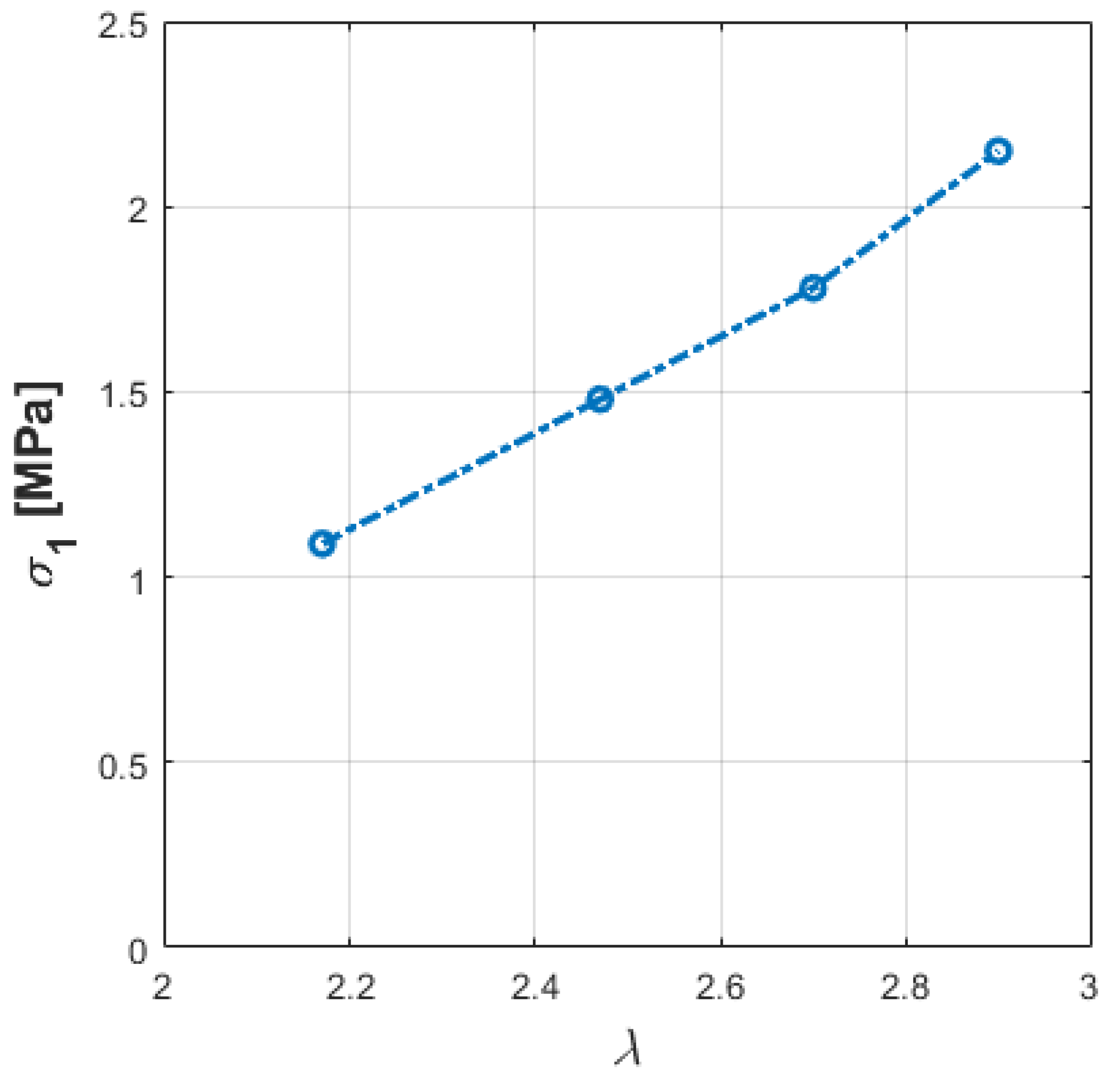
Table 2 were adopted to plot graphs useful for the procedure for fatigue life prediction. With reference to Equation (8),
Figure 6 reports the stress values
σ1 as a function of
λ;
Figure 7 reports the stress
σeq values as a function of the fatigue life duration, expressed in terms of number of cycles.
Results show that SFMs have a fatigue life duration too short and unsuitable for industrial applications. As expected, the fatigue life duration is reduced as the value of
λ increases. Similar results were achieved by [
36].
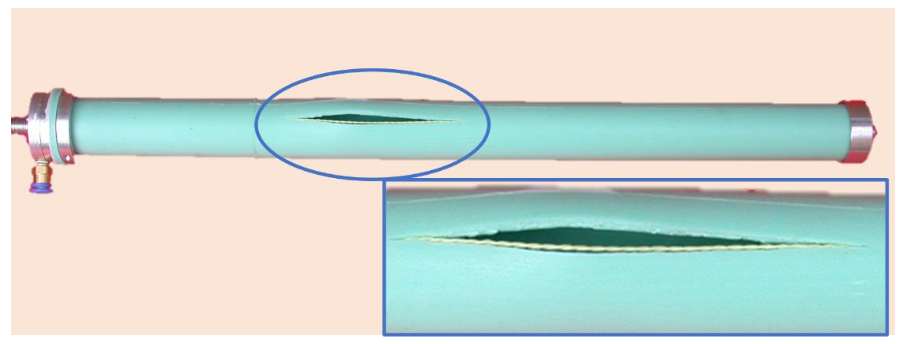
An example of a typical rupture occurred in a fatigue test of SFMs is shown in
Figure 8.
4. Model Validation
In this section, the procedure for fatigue life prediction is presented. Known
r0,
l0 and
l, by the dimensioning procedure that provides for the geometry and the shortening of the SFM,
ϕ is achieved by the graph reported in
Figure 3. Furthermore, by Equation (10),
λ can be achieved. When
λ is known, the stress σ
1, due to the deformation of the muscle in absence of an external load, can be achieved by the graph plotted in
Figure 6. The achieved stress σ
1 must be composed with the inner pressure,
σ2, according to Equation (8), in order to obtain the equivalent stress
σeq. The value of
σeq known, the fatigue life duration of the SFM is achieved by the graph plotted in
Figure 7. In order to validate the model, several predictions were carried out by the proposed procedure. All of them were experimentally checked: several prototypes of SFMs were realized and subjected to experimental tests in absence of an external load. All prototypes have the same
r0,
th and
n characteristics reported in
Table 1. Geometrical and functional parameters, the predicted and the experimental fatigue life durations of the experimental SFMs are reported in
Table 3.
The comparison between the predicted and the experimental results points out that the model is suitable for the fatigue life prediction with a maximum error of 11%. The discrepancy of 11% is due to the high dispersion that typically affects fatigue life duration data.
As a further check, consider that the muscle, under conditions of applied load equal to 500 N, can be brought up to the maximum pressure of 0.3–0.35 MPa. Under these conditions, from tests carried out, the deformation assumes the value
λ = 2.9, which is close to the maximum admissible value, and the muscle is close to breaking. Using the trend line of the graph in
Figure 7 for the forecast, we see that the duration would reduce to zero, as expected.
It should be noted that although the procedure is based on fatigue data relating to silicone rubber, it is valid for straight-fibers pneumatic muscles made of any material whose fatigue life is known.
5. Conclusions
The present work was focused on the fatigue of the straight-fibers pneumatic muscles. After introducing some theoretical aspects concerning the fatigue life of elastomeric materials, a model for the prediction of the life span of the McKibben muscle, found in literature, was analyzed. A procedure and a predictive model of the fatigue life duration of the straight-fiber pneumatic muscles were then presented. The procedure is based on experimental data collected in laboratory tests carried out with silicone rubber straight-fibers pneumatic muscles subjected to the overall feasible deformation range and without external loads acting on the muscles.
The model is based on the hypothesis according to which, in the most critical stressed area, the mechanical stress inside the elastomeric material of the tube is due to two stress components: the first one which is due to the circumferential deformation of the muscle, and is obtained through the circumferential strain ratio which is expressed by the operative radius to the resting radius ratio of the muscle; the second one depends on the operative pressure, strictly correlated to the force to be exerted by the muscle.
In determining the stress caused by circumferential deformation, a model is used that neglects any viscoelastic and hysteresis effects in the elastomeric material.
By means of the aforementioned hypothesis, using an equivalence criterium for the mechanical stresses, results were extended to those cases in which loads acting on muscles, or equivalently forces to be developed by the muscles, are different from zero for different values of deformation.
The procedure was experimentally validated and the predictions on the fatigue life duration, all over the feasible range of deformation, are accurate with a maximum error value equal to 11%. Although the experimental tests were carried out with muscles made of silicone rubber and the previsions are referred to it, whose database was developed in a previous research activity, the procedure remains valid and can be extended to all straight-fibers pneumatic muscles made of several elastomeric materials whose fatigue life duration database or experimental tests, equal to those presented here, are available. The knowledge of the fatigue life prediction of straight-fibers muscle is important in the research field in which the authors are working; in particular, the development of new assistive devices for rehabilitation and the development of collaborative robots to be adopted in domestic environments. Due to the direct interface and the sharing of the same workspace with humans, such devices must be intrinsically safe. Muscle actuators ensures this aspect. Nevertheless, at the same time, their life duration is an important aspect. The results of the presented research will help for better design.


 ,
, 


