Article

Analysis of Magnetic Field Characteristics of a Giant Magnetostrictive Actuator with a Semi-Closed Magnetic Circuit

1
Department of Vehicle and Electrical Engineering, Army Engineering University of People’s Liberation Army, Shijiazhuang 050003, China
2
Unit 63969 of People’s Liberation Army of China, Nanjing 210000, China
*
Author to whom correspondence should be addressed.
Actuators 2022, 11(4), 108; https://doi.org/10.3390/act11040108
Submission received: 25 March 2022 / Revised: 11 April 2022 / Accepted: 13 April 2022 / Published: 15 April 2022

Abstract

:
The internal magnetic field characteristics of giant magnetostrictive actuators have an important influence on their output performance. Aiming at the deficiency of current scholars’ research, based on the electromagnetic theory and finite element method, this paper analyzes the magnetic field intensity on a giant magnetostrictive cylinder by using COMSOL Multiphysics software. Considering the inhomogeneity of magnetic field intensity along the radial direction of giant magnetostrictive cylinders, a new averaging method is introduced to calculate the magnetic field intensity in the axial section of the cylinder. The influence of the magnetic permeability of the displacement conversion mechanism (shell) and the size of the air gap inside the device on the magnetic field intensity of the giant magnetostrictive cylinder are analyzed. The prototype of the actuator is manufactured, and the correctness and accuracy of the simulation data are verified by experiments. In order to make the magnetic field on the cylinder strong and uniform, the displacement conversion mechanism and the shell should be made of low permeability and high permeability materials, respectively, and the air gap size should be reduced as much as possible under the condition of meeting the size requirement of the actuator pre-tightening force applying device.

1. Introduction

Giant magnetostrictive material [1,2,3] (GMM) is a smart magnetic material with excellent performance. Compared with piezoelectric materials and other traditional magnetostrictive materials, it has a large magnetostrictive strain, large output force, and fast response speed, which is widely used in precision actuation, active control, and other fields. Using GMM as the energy-transducing material to develop giant magnetostrictive actuators for injectors [4,5,6] is one of the research hotspots in recent years. With the continuous improvement of machining and manufacturing technology, many scholars [7,8] considered designing giant magnetostrictive actuators (GMAs) for direct-drive injectors.
In the direct-drive fuel injector, in order to ensure the stability of the device, the working mode of the fuel injector is staying off when power is off. Generally, a displacement conversion mechanism needs to be added inside the actuator device to convert the displacement output direction of the actuator. The displacement conversion mechanism hardly affects the axial size of the actuator, but the mechanism is nested with the GMM cylinder, which affects the distribution of the magnetic field inside the material, thereby affecting the displacement output of the GMM cylinder; at the same time, the GMA shell isolates the device from the external air medium, the influence of its material properties on the magnetic density distribution on the GMM cylinder cannot be ignored. Therefore, it is necessary to analyze the influence of the mechanism and the GMA shell material on the magnetic field distribution of the GMM cylinder and optimize the conversion mechanism and the shell material in the design, so that the magnetic density on the GMM cylinder is large and uniform [9,10,11,12,13], the output displacement is large, and there is no sudden change in stress, which lays the foundation for the next step of actuator design and practical application.
The analysis of the internal magnetic density of the GMM belongs to the electromagnetic field problem, and the analytical method or the numerical method is generally used to solve the electromagnetic field problem. Using the analytical method to solve the electromagnetic field, the exact expression of the magnetic density can be obtained, and the distribution of the magnetic density can be accurately described. However, this is only limited to the more classical electromagnetic field problems. More complex electromagnetic field problems, especially multi-physics problems with coupling relationships, are difficult to solve by analytical methods [14]. And the use of numerical methods to solve electromagnetic field problems shows great advantages [15].
The finite element method [16] (FEM) is a numerical solution method that has emerged with the development of computers, and there are many commercial software programs in this area. Solving the GMA internal magnetic field problem with the help of mature simulation software has been one of the important means for many scholars to carry out research. Fan [17] established a 3D model of GMA with the help of Maxwell simulation software, took three axes at equal distances on the cross-section of the GMM cylinder, and calculated the average of the magnetic density on the three paths as the magnetic density in the GMM cylinder. Additionally, the influence of related magnetic circuit structure parameters on the magnetic field characteristics of the GMM cylinder was studied. Tu [18] established a plane axisymmetric model of GMA in ANSYS finite element software, taking the magnetic induction intensity at the central axis of the GMM rod as the research object, and studied the effect of related parameters on the magnetic density and uniformity of the GMM rod. Yu [19] designed a GMA driven by arrayed coils. A 2D plane model was established in COMSOL Multiphysics, and the magnetic induction intensity at the central axis of the rod was taken as the research object, and the magnetic field characteristics and magnetic field uniformity of the GMM under different height coil arrangements were studied. Tan [20] adopted the J–A model and identified the model parameters through a genetic algorithm and obtained the nonlinear constitutive model of magnetostriction; the two-dimensional axisymmetric model of GMA was established by using COMSOL Multiphysics finite element software, the distribution of the magnetic density was obtained inside the GMA, and the magnetic density at the geometric center point of the GMM rod was selected as the research object; ultimately, the relationship between the magnetic density and the input current was obtained. Gang [21] analyzed the process of solving the plane electromagnetic field problem by finite element method and obtained the magnetic density of GMM rod by finite element simulation. Six nodes were taken from each section of the GMM rod, and the algebraic average of the magnetic density of nodes was taken as the magnetic density value of this cross-section. The elongation of the GMM rod could be obtained by linear interpolation and trapezoidal integration, and the simulation results were verified by experiments. Yu [22] established finite element models of driving coils and cylindrical permanent magnets with the help of ANSYS simulation software and analyzed the influence of their size and other parameters on the average magnetic density and magnetic field uniformity of the GMA axis. Based on the simulation analysis, the optimization of the internal magnetic field of the GMA was completed.
The above scholars accurately solved the corresponding GMA magnetic density values through simulation calculation and obtained the corresponding research conclusions, which have certain guiding significance for the design of the GMA magnetic circuit and the optimization of magnetic field characteristics. However, when describing the magnetic density distribution characteristics on GMM, the geometric center or the algebraic average of multipoint magnetic density on the cross-section is used as the magnetic density of the cross-section. The above methods have low accuracy, unclear physical meaning, and insufficient consideration of the uneven distribution of the radial magnetic density of GMM, and their applicability needs to be expanded.
COMSOL Multiphysics is a finite element simulation software introduced in China in recent years. Based on the finite element method, the software realizes the simulation of real physical phenomena by solving partial differential equations or groups of partial differential equations [23]. In this paper, the simulation is based on the “magnetic field” physical field under the COMSOL Multiphysics 5.6 AC/DC module. A new averaging method is used to process the simulation results to obtain the magnetic density of the axial section of the GMM cylinder, draw the curve of the axial magnetic density distribution of the GMM cylinder, and define the magnetic density deviation degree to describe the magnetic field distribution deviation of the GMM cylinder; finally, the research conclusions are drawn by comprehensively considering the magnetic density and distribution uniformity on the cylinder. Based on the above conclusions, the influence of the geometric size of the air gap inside the GMA on the magnetic density distribution of the GMM cylinder is further discussed and analyzed. Finally, an experimental platform is built, and the correctness of the simulation is verified by experiments.

2. Principles and Methods

2.1. Basic Theory of Model Solving

The general law of the electromagnetic field is usually described by the concise form of Maxwell’s equations, and its differential form is
{ D = ρ B = 0 × E = B t × H = J + D t
where D is the electric flux density vector, for which the unit is C/m2; ρ is the charge density, and its unit is C/m3; B is the magnetic flux density vector, and its unit is Wb/m2; E is the electric field intensity vector, for which the unit is V/m; H is the magnetic density vector, unit A/m; J is the current density vector, unit A/m2; is the Hamiltonian operator, in the three-dimensional axisymmetric problem = ( r , φ , z ) .
To simplify the electromagnetic field problem, the electric and magnetic fields can be separated by a defined vector magnetic potential. The vector magnetic potential is defined as
B = × A
The defined vector magnetic potential automatically satisfies Gauss’s law of magnetic flux and Faraday’s law of electromagnetic induction and then applies it to Gauss’s law of electric flux and Ampere’s loop law; the partial differential equation of the magnetic field can then be obtained as follows:
2 A μ ε 2 A t 2 = μ J
x ( 1 μ A x ) + y ( 1 μ A y ) = J
where ε and µ are the permittivity and permeability of the medium, respectively, and 2 is the Laplace operator.
The COMSOL Multiphysics software can obtain the field distribution value of the magnetic potential. After conversion (postprocessing), various physical quantities of the electromagnetic field, such as magnetic density, magnetic flux density, etc. can be obtained.

2.2. COMSOL Multiphysics Finite Element Model Establishment

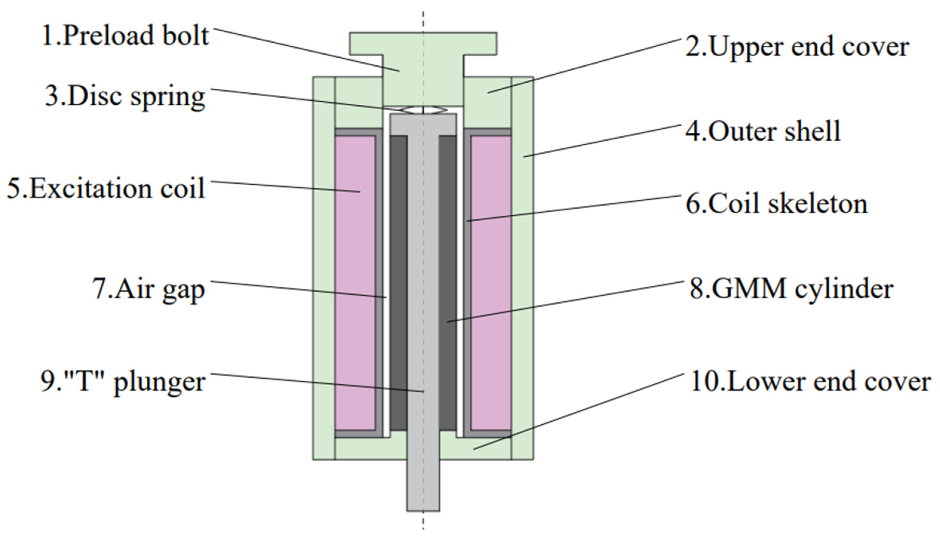
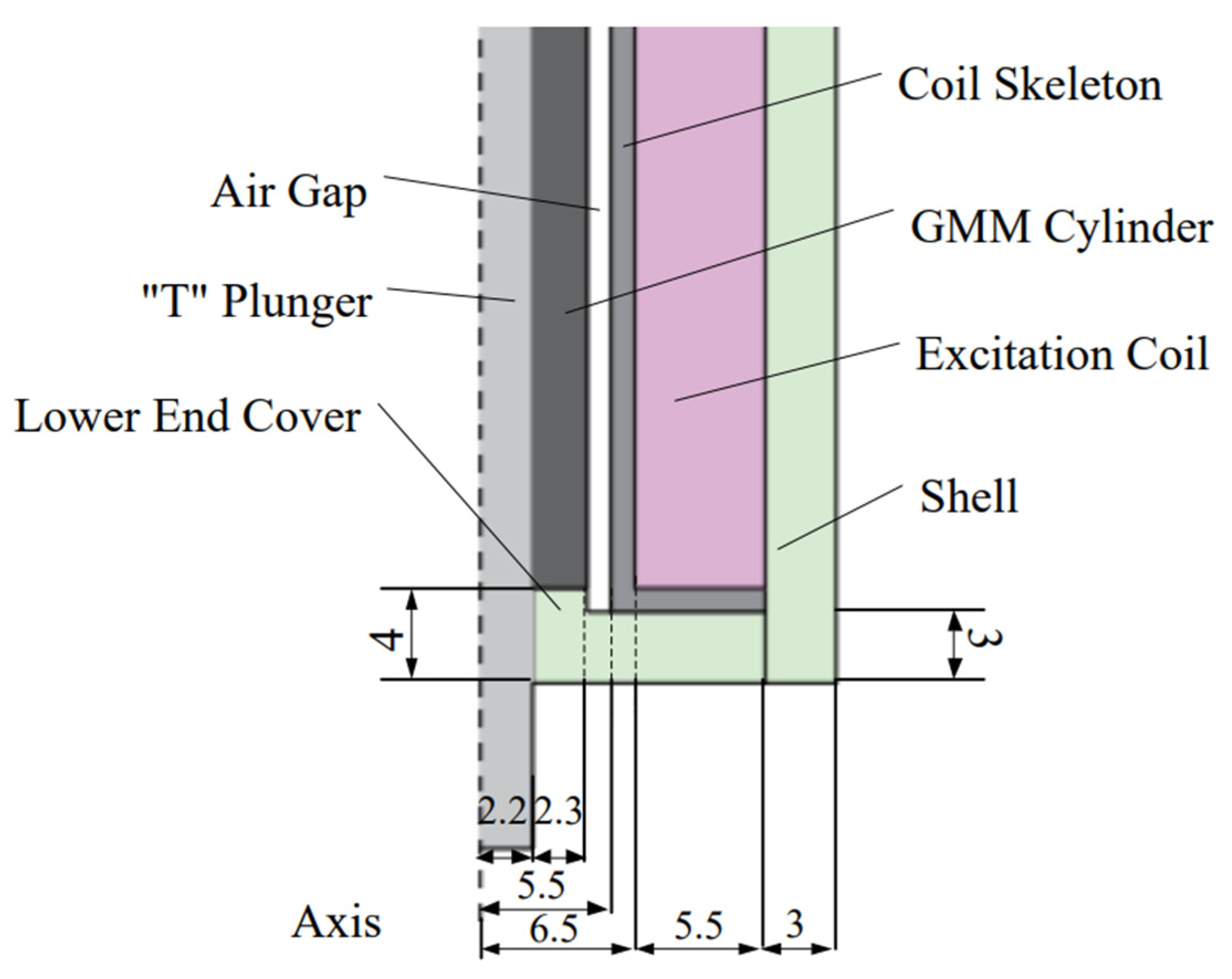
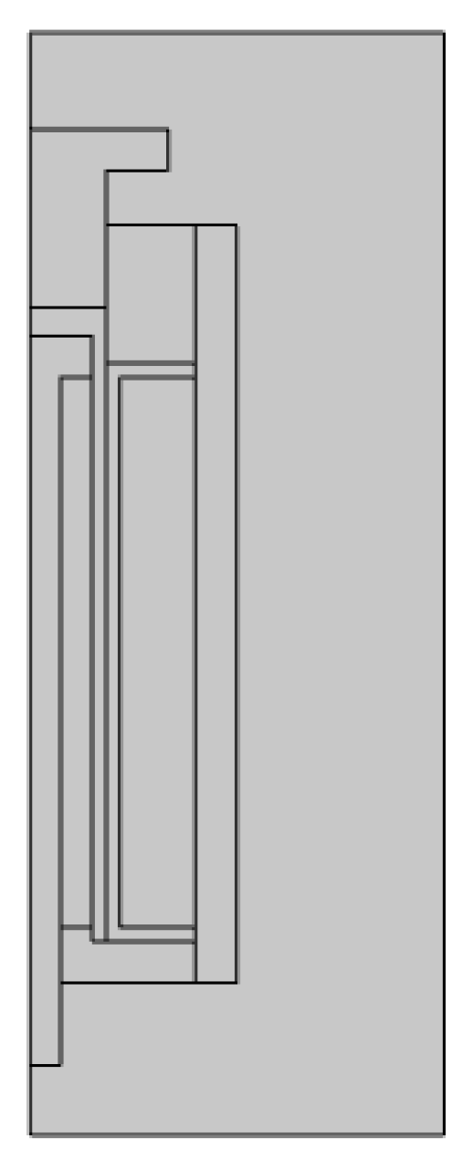
2.2.1. Finite Element Model

The structure of the direct-drive GMA device with the displacement conversion mechanism is shown in Figure 1. The displacement conversion mechanism needs to take into account the two functions of the output displacement direction conversion of the GMM cylinder and the application of prestress. The “T” plunger can well meet the above-mentioned requirements, and the integral structure can improve the overall rigidity of the device, so a “T” plunger was used as the displacement conversion mechanism. The GMM was designed as a cylindric structure and worked together with the “T” plunger to realize the conversion of the output displacement direction. The actuator material properties are shown in Table 1.
In which, ur is the relative magnetic permeability of the material, and the relative magnetic permeability of the disc spring can be ignored [19]. The ur value of the displacement conversion mechanism and the actuator shell (composed of preload bolt, outer shell, upper-end cover, and lower-end cover) were changed, respectively, and the influence of the material properties of the two on the distribution of the axial magnetic density of the GMM cylinder was analyzed and discussed.
The dimensions of some components in the actuator are shown in Figure 2. The radius of the “T” plunger rod was 2.2 mm, the thickness of the GMM cylinder was 2.3 mm, the thickness of the air gap and the coil skeleton was 1 mm, the inner diameter of the coil was 6.5 mm, and the outer diameter was 12 mm; the “T” plunger rodGMM cylinder and coil length were 40 mm.
The actuator was a three-dimensional axisymmetric structure, and a two-dimensional plane model was established in COMSOL Multiphysics, as shown in Figure 3.

2.2.2. Setting Boundary Conditions and Loads
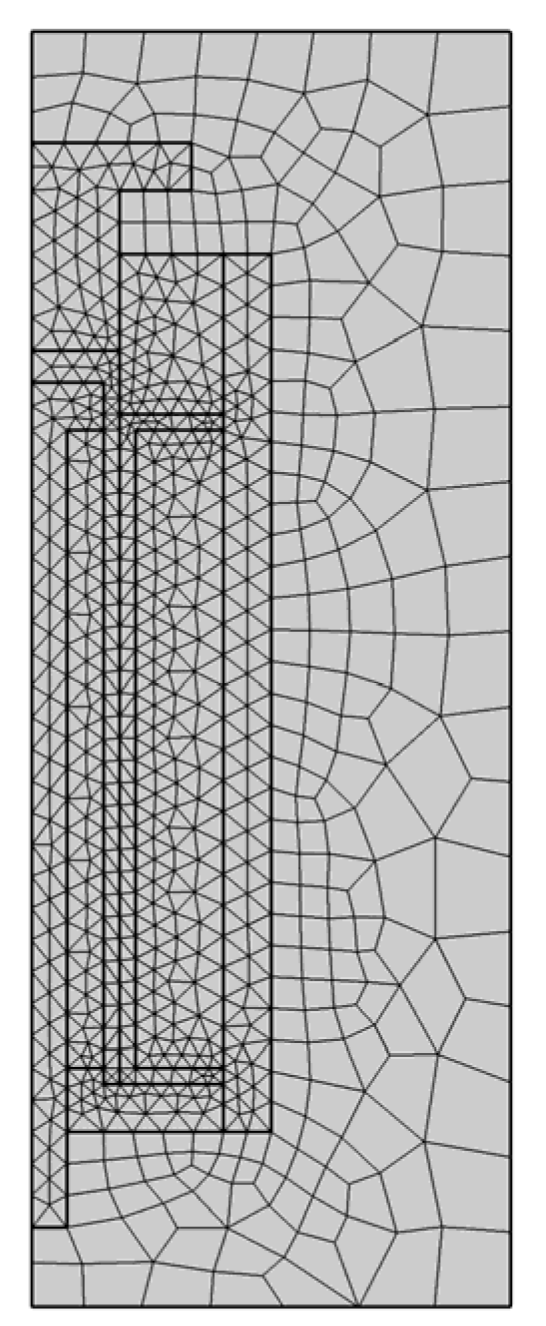
The “magnetic field” physical field under the AC/DC module in the COMSOL Multiphysics simulation software has two domain conditions by default, Ampere’s law and initial value, and two boundary conditions of axisymmetric and magnetic insulation. In addition, since the GMA is driven by the excitation coil, the coil domain condition should be added to apply the current load; therefore, the wire model was set to a uniform multiturn coil, the number of coil turns N was set to 500, and the coil current I was set to 4 A.

2.2.3. Meshing

Figure 4 is a schematic diagram of the mesh division of the geometric model. Since the magnetic density in the air domain outside the device was small and the change was gentle, the free quadrilateral mesh was used for the subdivision, and the free triangular mesh was used for the subdivision of other domains. The grid maximum size was limited to 0.5, and the maximum size of the free triangle mesh was limited to 0.1. The software solution time was reduced while ensuring the meshing accuracy.

2.2.4. Model Solution and Postprocessing

The research method was steady-state analysis, and the relative permeability of the displacement conversion mechanism (shell) was set to 1, 5, 10, 20, 40, 100, 200, 500, 1000, and 2000, respectively. After the software solution was completed, the strength of the magnetic field at any position on the GMM cylinder could be obtained. In COMSOL Multiphysics, color tables, streamlines, and isolines were used to describe the magnetic field intensity, as shown in Figure 5. Although this method can describe the distribution of the magnetic density in the entire device situation, the expression is not accurate enough and has little practical guiding significance. Therefore, this paper further processes the simulation results and establishes a new data set for analysis.

2.3. Establishing a Coordinate System

In this study, we used the COMSOL Multiphysics software to simulate and analyze the magnetic field distribution on the GMM cylinder. In order to conveniently and accurately describe the magnetic field distribution on the cylinder, a separate coordinate system Orl was established for it, as shown in Figure 6. The magnetic field distribution on the GMM cylinder was defined by the component of the magnetic field intensity along the cylinder axis (direction l in Figure 6).

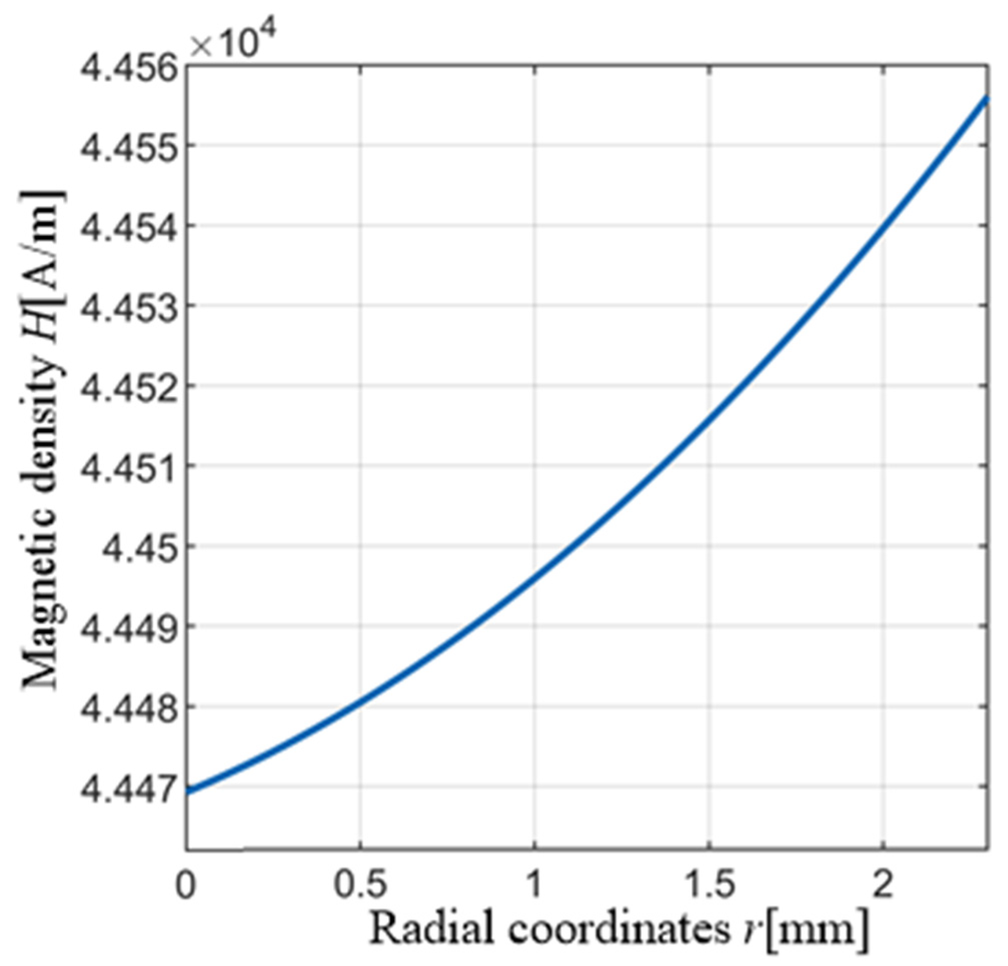
2.4. Solving the Cross-Sectional Magnetic Density

The axial distribution of the magnetic density on the GMM cylinder can be described by the magnetic density on the axis passing through the appropriate position of the GMM cylinder, as shown in Figure 7a, or the algebraic average value of the magnetic density on any section of the GMM cylinder can be obtained as the value of the magnetic density of the section, as shown in Figure 7b. However, the above methods have problems such as low description accuracy or unclear physical meaning and fail to fully consider the inhomogeneity of the radial magnetic density distribution of the GMM cylinder. Therefore, based on the law of the magnetic circuit and the inhomogeneity of the magnetic density distribution in the radial direction of the cylinder, a new averaging method is proposed to solve the magnetic density on the section of the GMM cylinder.
Similar to the circuit theory, the physical model of the magnetic field can be abstracted as a magnetic circuit model [24], and the magnetic flux of the main circuit in the magnetic circuit is equal to the sum of the magnetic flux of the branch circuits. On the other hand, the radial magnetic density distribution of any section of the cylinder can be obtained through simulation. Under the initial simulation parameters, running the simulation software found that the magnetic field intensity of the GMM cylinder increased along the radial dimension, and the changing trend of the magnetic field intensity in the middle section of the cylinder with the increase in the radial dimension r is shown in Figure 8; the magnetic density H increased monotonically on the radial coordinate r of the GMM cylinder, from 4.4470 × 10 4 A/m to 4.4560 × 10 4 A/m. Taking the above two points into consideration, and at the same time, to simplify the calculation, in this study, we divided the section of the GMM cylinder into different areas and assumed that the magnetic density distribution is uniform in each area.
Using the COMSOL Multiphysics simulation software, the magnetic density components at four points on any section of the GMM cylinder were obtained. As shown in Figure 9, the points r on the cylinder were 2.35, 2.75, 3.25, and 4 mm, respectively, and four circles with radii of 2.5, 3, 3.5, and 4 mm were made, which divided the GMM cylinder into four areas.
Then, there is
μ H S = μ i = 1 4 H i S i
H = 1 S i = 1 4 H i S i
where µ is the absolute permeability of the GMM cylinder. The cross-sectional area of the GMM cylinder is S, the area of the divided area is Si, and the magnetic density component is Hi.
Substituting data, the magnetic density of the GMM cylinder cross-section can be obtained as
H = 1 1541 ( 141 H 1 + 275 H 2 + 325 H 3 + 800 H 4 )  
In the subsequent analysis of the axial magnetic density, Formula (7) was used to determine the magnetic density of the section at any coordinate point in the axial direction.

3. Results and Discussion

3.1. Simulation Verification

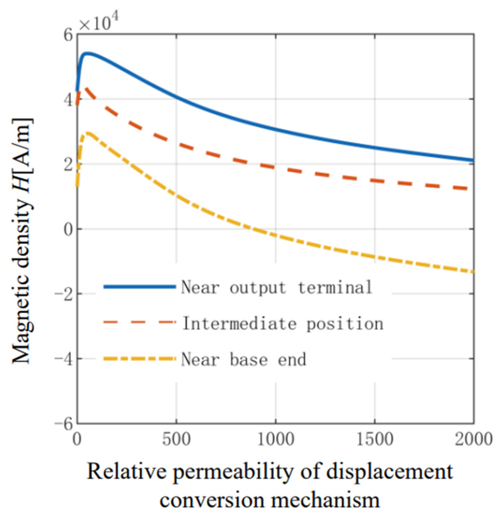
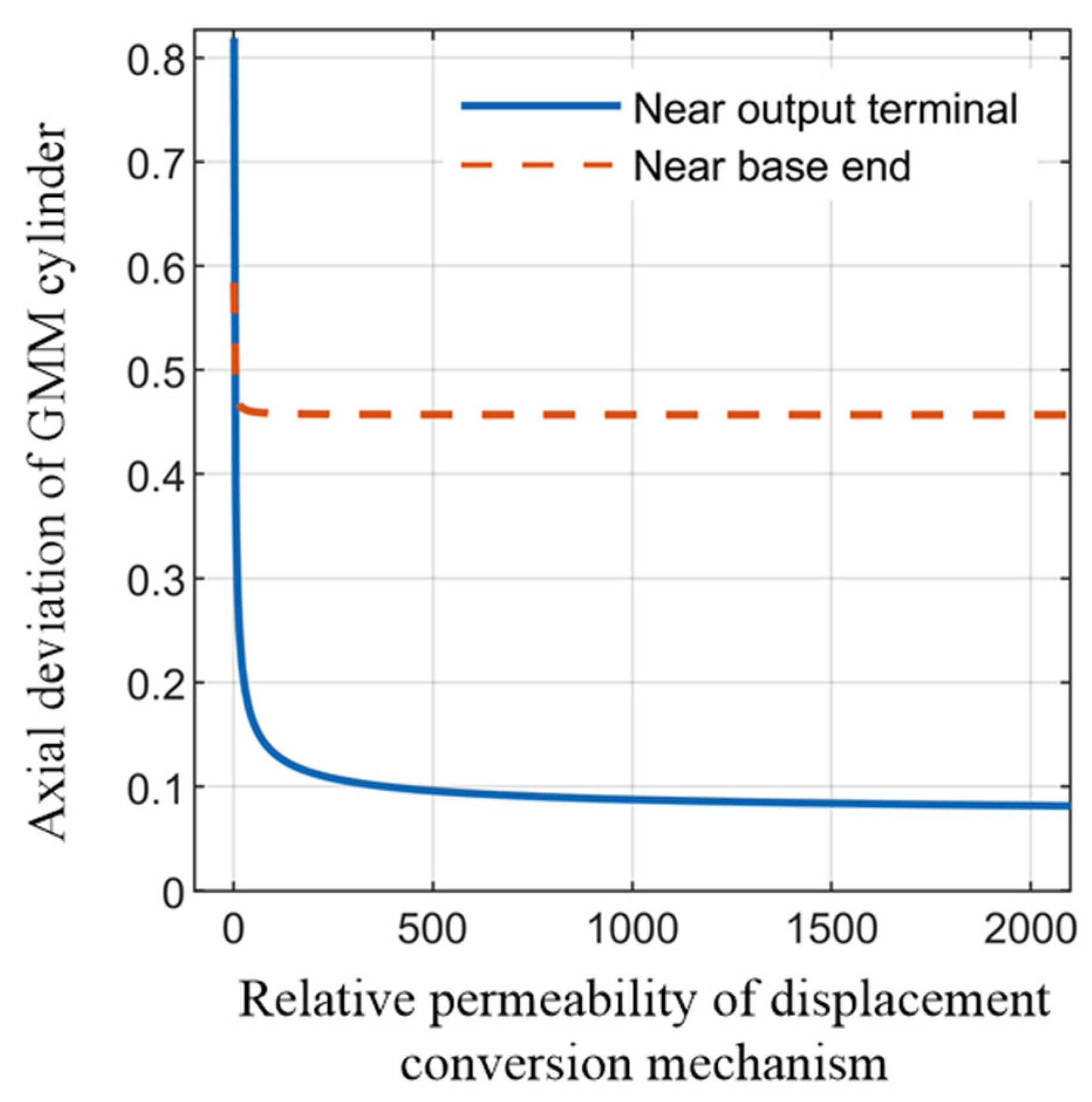
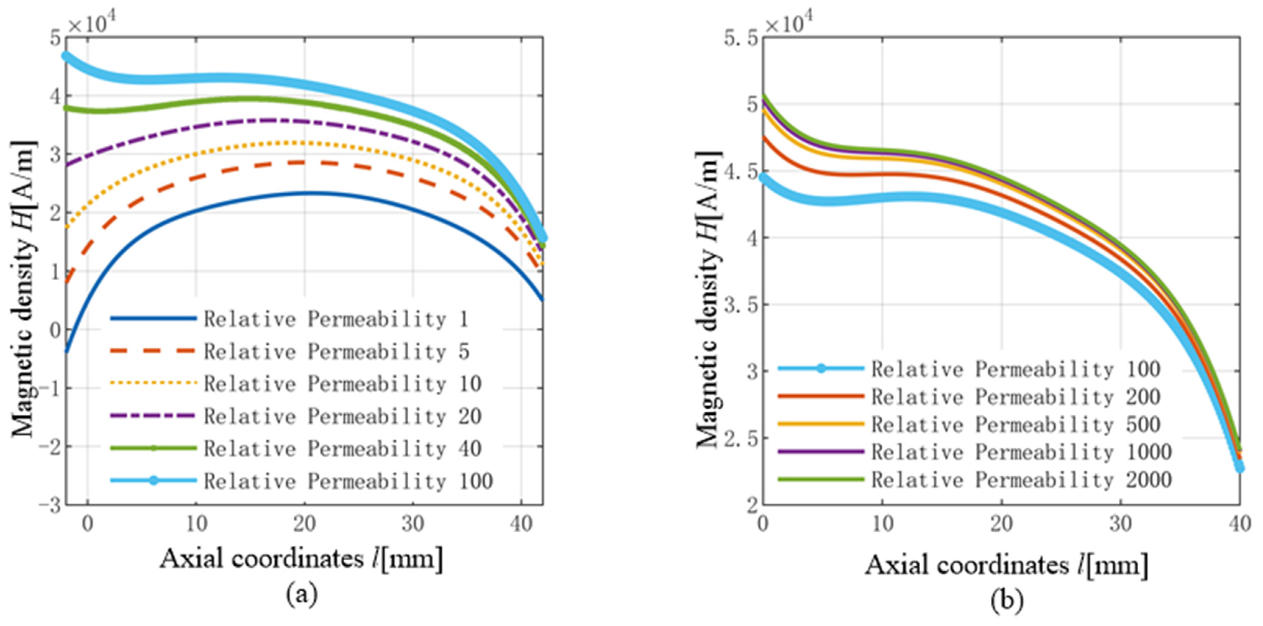
3.1.1. Influence of Displacement Conversion Mechanism on Magnetic Field Distribution Characteristic

A large number of studies [17,25,26,27] have shown that the use of high permeability materials for the device shell can close the magnetic circuit and maximize the efficiency of magnetic field utilization. Therefore, in the simulation analysis here, the relative permeability ur of the shell material was set to 2000. The relative magnetic permeability of the displacement conversion mechanism was changed, the magnetic density of each section was obtained, respectively, and the data fitting was performed on the obtained results to obtain the axial magnetic density distribution of the GMM cylinder shown in Figure 10. Figure 11 shows the change in the magnetic density of the GMM cylinder near the output end, the middle part, and the near base end with the relative permeability of the displacement conversion mechanism.
It can be seen from the simulation results that the magnetic density in the middle of the cylinder was relatively uniform; the magnetic density near the output end was relatively large, and the magnetic density near the base end was relatively small, which is related to the displacement conversion mechanism and the magnetic permeability of the material at both ends of the cylinder. With the increase in ur, the magnetic density of the GMM cylinder near the output end, the middle part, and the near base end first increased and then decreased: the magnetic density near the output end reached the maximum value of 5.355 × 10⁴ A/m around ur = 30; the magnetic density at the middle reached the maximum value of 4.553 × 10⁴ A/m near ur = 20; the magnetic density near the base end reached the maximum value of 2.93 × 10⁴ A/m near ur = 40. Through simulation analysis, it was found that when the displacement conversion mechanism ur < 100, the magnetic density on the cylinder changed greatly. In the range of 0 to 100, the variation amplitude of magnetic density could reach 1.0 × 10⁴ A/m; when ur ≥ 100, the magnetic density changed relatively gently, which is because the displacement conversion mechanism is nested with the GMM cylinder, and the relative permeability of the GMM cylinder is small (ur = 20). Therefore, when the relative magnetic permeability of the displacement conversion mechanism changed around 20, the influence on the distribution of magnetic density was more significant, and when the relative permeability of the displacement conversion mechanism exceeded the critical point (ur = 100), the influence on the distribution of the magnetic density on the cylinder weakened.
In order to describe the deviation of the magnetic density between the two ends of the GMM cylinder and the middle part, and the influence of the relative permeability of the displacement conversion mechanism on this deviation, the axial magnetic density deviation p is defined as
{ p 1 = H max H A H A p 2 = H A H min H A
where HA represents the magnetic density value of the middle section of the GMM cylinder; Hmax and Hmin represent the maximum magnetic density value near the output end of the GMM cylinder and the minimum magnetic density value near the base end, respectively. p1 represents the degree of deviation of the magnetic density near the output end, and p2 represents the degree of deviation of the magnetic density near the base end. The changes in the two with the relative permeability of the displacement conversion mechanism are shown in Figure 12. Through simulation, it was found that with the increase in ur, the magnetic density deviation at the base end first decreased and then increased, and the minimum value was 0.3026 when ur = 90, and the change range was large; the magnetic density deviation near the output end increased monotonically, and the increase was small, which is related to the displacement conversion mechanism and the magnetic permeability of the material at both ends of the cylinder. When ur = 20, the average deviation of the magnetic density between the two achieved the minimum value of 0.28345.
The simulation results showed that the relative permeability of the displacement conversion mechanism had a great influence on the distribution of the magnetic density on the GMM cylinder. In particular, when ur = 1, the magnetic permeability of the material was the same as that of air; when ur > 1, the displacement conversion mechanism was nested with other components of the GMA, affecting the distribution of the magnetic density.
Combined with the simulation results of Figure 10, Figure 11 and Figure 12, and considering the axial magnetic density of the GMM cylinder and the deviation of the magnetic density, it can be seen that when the displacement conversion mechanism ur ≈ 10, the magnetic density on the GMM cylinder was larger, and the distribution uniformity was good. Based on this conclusion, when discussing the influence of the shell ur on the magnetic density of the GMM cylinder, the displacement conversion mechanism material ur was set to 10 in the COMSOL Multiphysics simulation software.

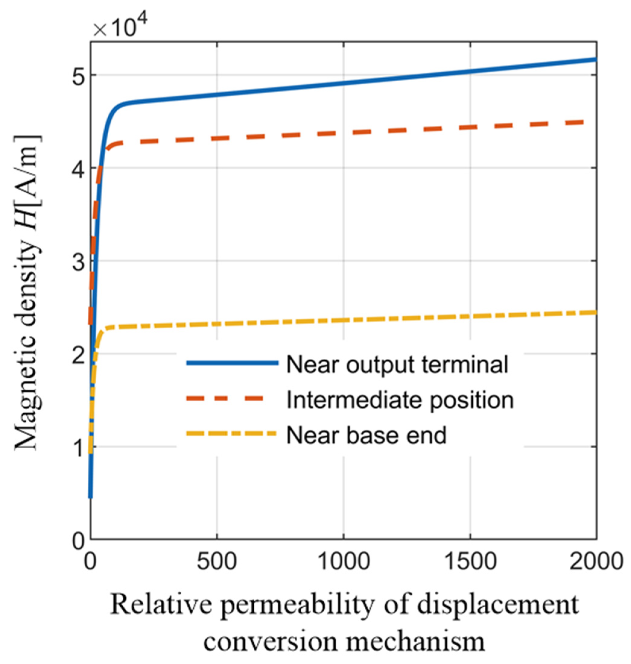
3.1.2. Influence of Shell on Magnetic Field Distribution Characteristic

By changing the relative permeability of the shell, the distribution of the axial magnetic density of the GMM cylinder was determined, which is shown in Figure 13. The magnetic density of the GMM cylinder near the output end, the middle part, and the base end changed with the relative permeability of the shell, as shown in Figure 14. It can be seen from the simulation results that the magnetic density distribution in the middle part of the cylinder was relatively uniform; when ur < 45, the magnetic density near the output end was smaller than that in the middle part; when ur ≥ 45, the magnetic density near the output end exceeded the middle part; the magnetic density near the base end was obviously lower than that of the middle part and the magnetic density near the output end.
Through the simulation analysis, it was found that with the increase in ur of the shell, the magnetic density on the GMM cylinder increased accordingly. This is because the torsional effect of the shell on the magnetic field lines is continuously strengthened, and more magnetic field lines are closed in the device loop. In particular, when ur < 90, the magnetic density on the cylinder increased greatly: the magnetic density near the output increased from 6.678 × 10³ A/m to 4.673 × 10⁴ A/m; the magnetic density in the middle increased from 2.431 × 10⁴ A/m to 4.237 × 10⁴ A/m; the magnetic density near the base increased from 1.045 × 10⁴ A/m to 2.284 × 10⁴ A/m.
Here, the influence of the shell ur on the deviation of the axial magnetic density of the GMM cylinder is described by referring to the definition in Equation (8). However, because under different shell ur conditions, the maximum values near the output end were not all larger than the magnetic density at the middle part, so the deviation of the axial magnetic density is defined as
{ p 1 = | H max H A | H A p 2 = H A H min H A
It is easy to infer that p1 and p2 are the deviations of the magnetic density near the output end and the near base end, respectively, and the changes in the two with the relative permeability of the shell are shown in Figure 15. It can be seen from the simulation results that when ur < 5, the deviation of the magnetic density at both ends of the GMM cylinder was larger, and the deviation of the magnetic density at the near output end was greater than that at the near base end. As ur increased, the magnetic density at both ends decreased rapidly, and the uniformity of the magnetic field was enhanced. As the relative magnetic permeability of the displacement conversion mechanism was small, and the near-base end of the GMM cylinder was in contact with the head of the “T”-type plunger, the magnetic density near the base end was small. Therefore, when the shell had ur ≥ 5, the deviation of the magnetic density near the base end was much larger than that near the output end. The deviation of the average magnetic density at both ends had the minimum value of 0.26922 when ur = 2000.
The simulation results showed that the relative magnetic permeability of the shell had a great influence on the distribution of the magnetic density on the GMM cylinder. In particular, when ur = 1, the magnetic permeability of the material was the same as that of air; it is worth noting that the internal medium of the device was connected with the external air medium; when ur > 1, the shell worked with other components of GMA to separate the inner space of GMA from the external air medium, which affected the distribution of the magnetic density on the GMM cylinder.
Combined with the simulation results shown in Figure 13, Figure 14 and Figure 15, and considering the axial magnetic density of the GMM cylinder and the deviation of the magnetic density, the device shell should be made of high-permeability materials. This conclusion further verified the views of relevant scholars [18,28].
Based on the above simulation results, in the subsequent analysis and optimization of the size, the relative permeability of the displacement conversion mechanism material was set to 10, and the relative permeability of the shell material was set to 2000.

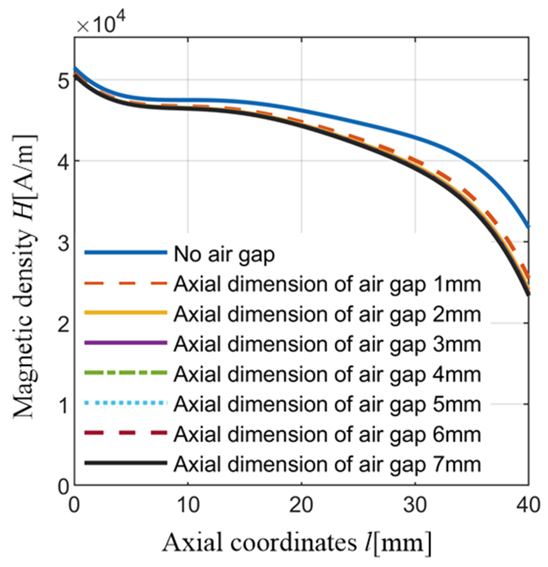
3.1.3. Influence of Air Gap Geometry on Axial Magnetic Density of GMM Cylinder

Considering the constraints of the installation size of the injector, the structure size of the GMA was basically fixed, and there were few parameters that can be optimized. Due to component processing and assembly issues, air gaps inevitably appeared in GMA. The existence of the air gap has an important influence on the magnetic field characteristics of the GMA. However, many scholars often ignore the influence of the air gap in the research process, which affects the accuracy of the research results to a certain extent. The effect of the air gap size d on the magnetic density distribution on the cylinder is discussed below.
The internal air gap of GMA can be divided into two parts: one part is the assembly gap between the GMM cylinder and the coil bobbin. After the actuator was assembled, its size was difficult to change, and the radial thickness of the gap was about 1 mm, which can be ignored; in addition, there was an air gap between the preload bolt and the “T” plunger. Due to the existence of the disc spring, its geometric size was large (the axial diameter was about 5 mm). By selecting disc springs with different lengths and stiffnesses to match the preload bolts, the size of the air gap could be adjusted under the condition that the GMA preload force was met (in fact, only changing the axial size of this part of the air gap). The axial size of this part of the air gap was set to 0, 1, 2, 3, 4, 5, 6, and 7 mm, respectively, and COMSOL Multiphysics was run to simulate the influence of the air gap size on the magnetic density distribution on the GMM cylinder.
When the air gap size was changed, the distribution of the axial magnetic density of the GMM cylinder is shown in Figure 16, and the magnetic density of the GMM cylinder near the output end, the middle part, and the near base end is shown in Figure 17. When the size of the air gap was increased, the magnetic density on the GMM cylinder decreased. The magnetic density near the base changed greatly, and the magnetic density in the middle part changed relatively gently, while the magnetic density near the output end did not change much. This is because the air gap was close to the side near the base end, and the closer it was to the air gap, the greater the influence on the magnetic density of the GMM cylinder. When the air gap size increased from 0 to 2 mm, the magnetic density on the cylinder changed greatly, especially near the base end; the magnetic density decreased from 3.172 × 10⁴ A/m to 2.402 × 10⁴ A/m.
Here, the effect of the air gap size on the deviation of the axial magnetic density of the GMM cylinder is described by referring to the definition in Equation (8). The variation in the magnetic density deviation of the GMM cylinder with the size of the air gap is shown in Figure 18. When the air gap size increased, the deviation of the magnetic density at both ends of the cylinder increased; the increase near the base end was larger, and the uneven distribution of the magnetic field on the GMM cylinder increased.
Through simulation analysis, it was found that increasing the size of the air gap reduced the magnetic density on the GMM cylinder and increased the deviation of the magnetic density. In order to make the magnetic density on the GMM cylinder larger and the distribution uniformity better, the length and stiffness of the disc spring should be reasonably selected to match the pretightening bolt or the way of applying the preload force should be optimized to reduce the size of the air gap as much as possible.

3.2. Experimental Verification

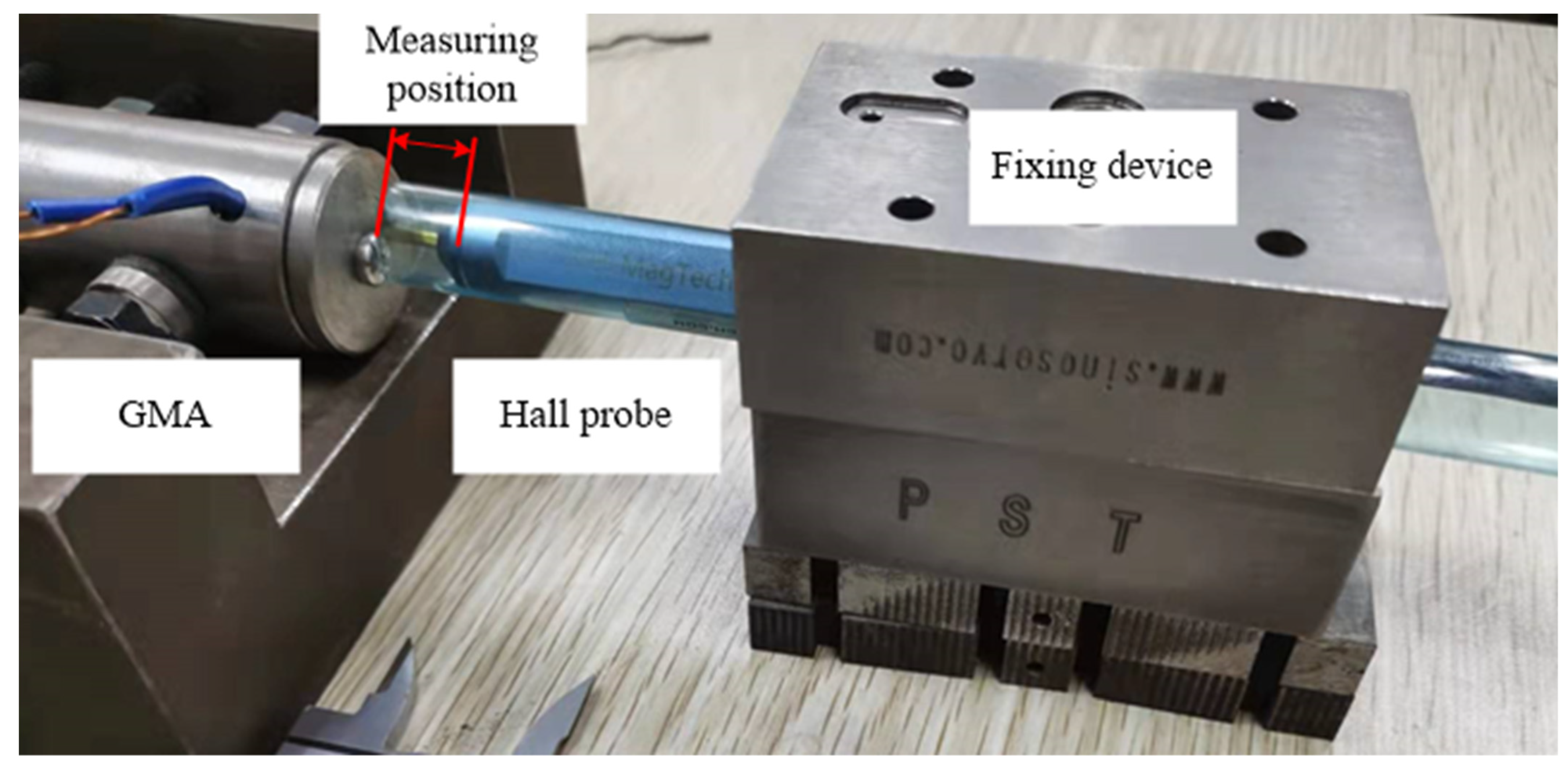
3.2.1. Experimental System

An experimental test system was set up, as shown in Figure 19. AC electrical signals were amplified by a power amplifier and input into GMA. The internal magnetic field intensity of GMA was measured by a Gaussmeter. The front transverse Hall probe collected the experimental data through an oscilloscope and input it into a computer for storage. The model of the digital storage oscilloscope is PS2000, the model of the power amplifier is YE5874A, the model of the Gaussmeter is CH-1600, and its front-end device is Model-MCHD801F Hall probe. The GMA prototype was manufactured, as shown in Figure 20. In order to facilitate the penetration of the Hall probe, the upper-end cover of GMA was provided with a groove.
Five measuring points were taken at equal intervals on the outer wall of the GMM cylinder, as shown in Figure 21. During the test, the Hall probe clung to the outer wall of the GMM cylinder, and the radial magnetic field intensity at the outer wall of the GMM cylinder was measured.

3.2.2. Comparison between Simulation Results and Experimental Results

Preheat Hall probe and Gaussmeter were used for 5 min and 30 min, respectively. Sinusoidal alternating current with an amplitude of 2A and frequency of 25 HZ was inputted, and measurements were taken. During measurement, GMA was clamped with clamping fittings, restricting the movement of the Hall probe by fixing the device; the distance from the end of GMA to the end of the Hall probe was then measured with a vernier caliper, so as to realize the accurate positioning of measuring points, as shown in Figure 22.
The experimental test results and simulation results of radial magnetic field intensity of five test points were obtained, respectively, as shown in Figure 23a–e. The distribution of radial components of magnetic field intensity along the axial coordinates is shown in Figure 23f.
By comparing the experimental results with the simulation results, it was found that they are in good agreement, and the simulation results can accurately describe the radial magnetic field intensity and its distribution on the GMM cylinder. Due to the magnetic leakage of the device and the inevitable errors introduced in the experiment process, there was a certain deviation between the experimental results and the simulation results. In order to analyze this deviation, the relative error of magnetic field intensity is defined as eH.
e H = H S H E H E × 100 %
where HS is the simulation result, and HE is the experimental test result. Through calculation, it was found that the maximum relative error appeared at the fourth measuring point, which was about 8.5%, and the relative errors of other measuring points were all less than 5%. Therefore, it can be considered that the simulation analysis carried out in this paper can accurately reflect the real physical phenomena and verify the correctness of the established simulation model.

4. Conclusions

In this paper, COMSOL Multiphysics finite element software was used to simulate and analyze the internal magnetic field characteristics of GMA for direct-drive fuel injectors, and an experimental test system was built. The simulation model was verified by experiments. The following observations were made:
(1)
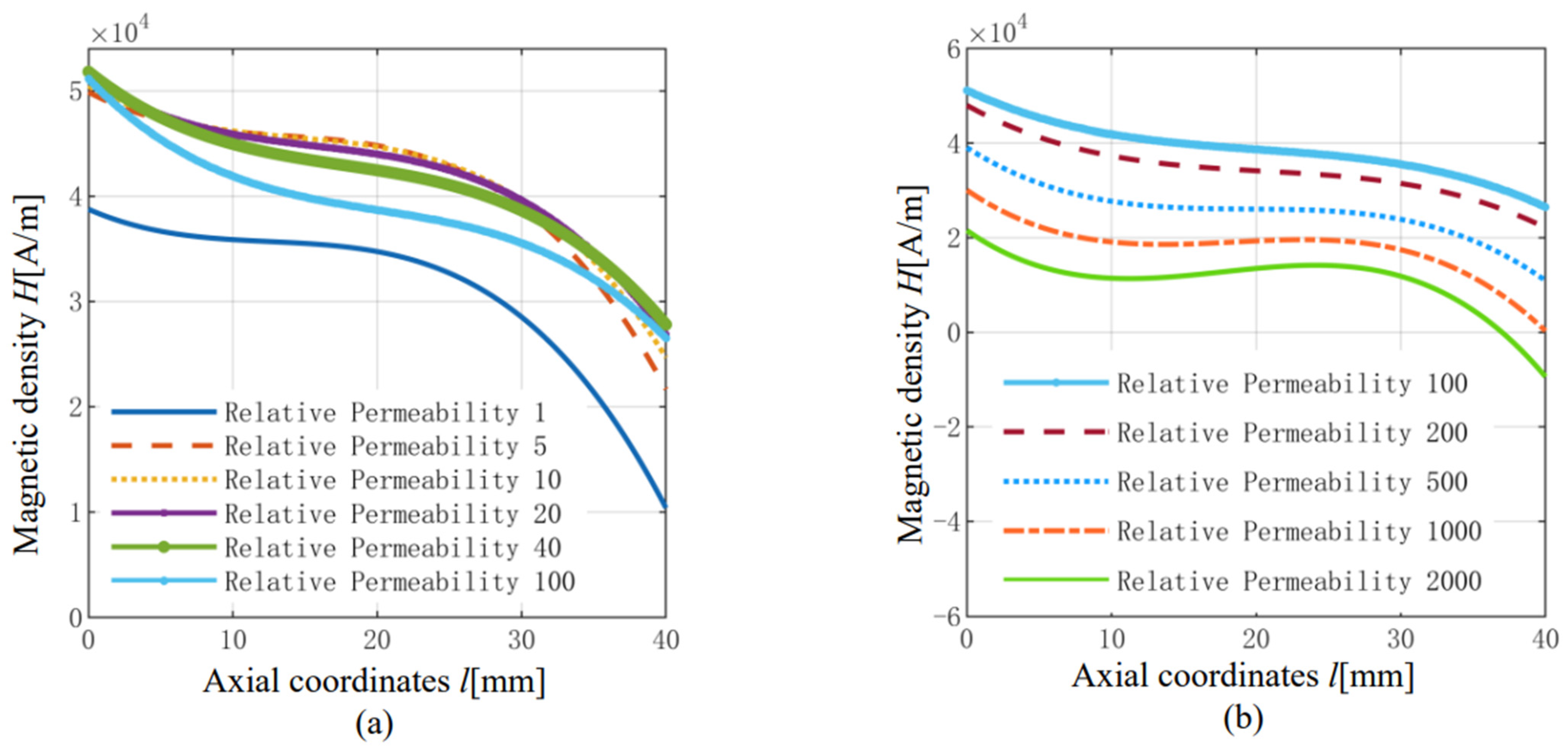
By increasing the relative permeability of the transfer mechanism, the magnetic field intensity on the GMM cylinder first increased and then decreased, whereas the deviation of the average magnetic field intensity at both ends first decreased and then increased. In order to make the axial magnetic field intensity of the GMM cylinder larger and more uniform, the displacement conversion mechanism should be made of materials with low magnetic permeability.
(2)
When the relative permeability of the shell increased, the magnetic field density on the GMM cylinder increased monotonously, and the deviation of magnetic field density at both ends decreased monotonously. In order to make the axial magnetic field intensity of the GMM cylinder large and uniform, the device shell should be made of high-permeability material.
(3)
With the increase in air gap size, its constraint on magnetic field lines weakened, the magnetic field density on the GMM cylinder decreased, and the deviation degree of magnetic field density increased. Therefore, in order to improve the utilization efficiency of the excitation magnetic field, the geometric size of the air gap should be reduced as much as possible under the condition of meeting the pretightening force requirements.
(4)
The experimental test results showed that the established simulation model can correctly reflect the actual physical characteristics of GMA, and it was also verified that it is feasible to use the averaging method based on magnetic circuit theory to solve the magnetic field intensity of GMM cylinder axial section.
The research content of this paper provides a new idea for the analysis, design, and optimization of GMA magnetic circuits. However, when describing the axial magnetic field intensity distribution on the GMM cylinder, based on the magnetic circuit theory, it is difficult to further improve the calculation accuracy by using finite points to calculate the magnetic field intensity on the cross-section. Therefore, in the next stage of the research, we should consider establishing the analytical solution of the magnetic field spatial distribution of the excitation coil or adopting a new calculation method based on the finite element simulation method so that we can comprehensively consider the radial magnetic field intensity distribution of a certain component and realize the accurate solution of the magnetic field intensity inside GMA.

Author Contributions

Conceptualization, Z.H. and G.X.; methodology, Z.Z.; software, Z.Z.; validation, Z.Z., C.R. and G.L.; formal analysis, Z.Z.; investigation, Z.Z.; resources, J.Z.; data curation, J.Z.; writing—original draft preparation, Z.Z.; writing—review and editing, Z.Z.; visualization, J.Z.; supervision, Z.H.; project administration, Z.H.; funding acquisition, J.Z. All authors have read and agreed to the published version of the manuscript.

Funding

This research received no external funding.

Conflicts of Interest

The authors declare no conflict of interest.

References

  1. Zhou, S.; Gao, X. Magnetostrictive Materia, 1st ed.; Metallurgical Industry Press: Beijing, China, 2017; pp. 1–10. [Google Scholar]
  2. Engdahl, G. Handbook of Giant Magnetostrictive Materials; Academic Press: San Diego, CA, USA, 2000. [Google Scholar]
  3. Liu, J.; Jiang, C.; Xu, H. Giant magnetostrictive materials. Sci. China Technol. Sci. 2012, 55, 1319–1326. [Google Scholar] [CrossRef]
  4. Xue, G.; Ge, J.; Ning, P.; Zhou, J.; Wang, K.; Cheng, Z.; Pei, G. Simulation studies on the boot shape injection of a giant magnetostrictive injector. Sci. Rep. 2021, 11, 22999. [Google Scholar] [CrossRef] [PubMed]
  5. Xue, G.; Zhang, P.; He, Z.; Li, D.; Yang, Z.; Zhao, Z. Displacement model and driving voltage optimization for a giant magnetostrictive actuator used on a high-pressure common-rail injector. Mater. Des. 2016, 95, 501–509. [Google Scholar] [CrossRef]
  6. Li, Y.; Zhang, P.; He, Z. A simple magnetization model for giant magnetostrictive actuator used on an electronic controlled injector. J. Magn. Magn. Mater. 2019, 472, 59–65. [Google Scholar] [CrossRef]
  7. Gahodsi, M.; Ozer, A.; Yahmadi, A.A. Development of Gasoline Direct Injector Using Giant Magnetostrictive Materials. In Proceedings of the 2014 International Conference on Renewable Energy Research and Application (ICRERA), Milwaukee, WI, USA, 19–22 October 2014. [Google Scholar]
  8. Xu, B. Structure Design and Characterstic Analysis of High Pressure Common Rail Injector Based on Giant Magnetostrictive Actuator; Anhui University of Science and Technology: Huainan, China, 2020. [Google Scholar]
  9. Xue, G.; He, Z.; Li, D. Magnetic field intensity model for giant magnetostrictive rodand coil optimization analysis. Nanotechnol. Precis. Eng. 2014, 12, 85–90. [Google Scholar]
  10. Chen, J.; Wang, L.; Tang, Y.; Zhou, H. GMA internal magnetic field measurement based on FBG.In Proceedings of the Tenth International Symposium on Precision Engineering Measurements and Instrumentation. SPIE 2019, 11053, 213–221. [Google Scholar]
  11. Li, D. Study on 3D internal magnetic field distribution and dynamic mechanics of a giant magnetostrictive actuator. J. Supercond. Nov. Magn. 2018, 31, 4013–4020. [Google Scholar] [CrossRef]
  12. Liu, H.; Gao, S.; Wang, H. Study on eddy current loss characteristics of precision giant magnetostrictive actuator considering magnetic field distribution. Int. J. Nanomanuf. 2019, 15, 343–354. [Google Scholar] [CrossRef]
  13. Zheng, J.; He, Z.; Zhou, J. Distribution Structure Design on Bias Magnetic Field of Giant Magnetostrictive Actuator for Hydraulic Valve. Chin. Hydraul. Pneum. 2018, 9, 33. [Google Scholar]
  14. Wang, G.; An, L. COMSOL Multiphysics Engineering Practice and Theoretical Simulation: Numerical Analysis Technology of Multiple Physical Fields, 1st ed.; Electronic Industry Press: Beijing, China, 2012; pp. 67–81. [Google Scholar]
  15. Xue, G.; He, Z.; Li, D. Analysis on magnetic field distribution of giant magnetostrictive actuator based on a displacement transmission mechanism. Mech. Sci. Technol. Aerosp. Eng. 2014, 33, 1259–1263. [Google Scholar]
  16. Reddy, J.N. Introduction to the Finite Element Method, 4th ed.; McGraw-Hill Education: New York, NY, USA, 2019; pp. 591–668. [Google Scholar]
  17. Fan, W.; Lin, M.; Ju, X. Research and simulation of magnetic field of cylindrical hypermagnetic actuator. J. Funct. Mater. 2017, 48, 5054–5060. [Google Scholar]
  18. Tu, J.; Liu, Z.; Li, Z. Magnetic circuit optimization design andfinite element analysis of giant magnetostrictive actuator. J. Chongqing Univ. 2021, 44, 52–63. [Google Scholar]
  19. Yu, Z.; Zhao, H.; Zhang, C. Modeling and simulation of axial non-uniform magnetic field for giant magnetostrictive actuator. J. Magn. Mater. Devices 2019, 50, 10–16. [Google Scholar]
  20. Tan, X.; Yang, B.; Meng, G.; Xu, P.; Yang, D. Displacement Model and Finite Element Analysis of Two-dimensional Axisymmetric Nonlinear Drive for Giant magnetostrictive Actuator. Astron. Res. Technol. 2010, 7, 362–368. [Google Scholar]
  21. Gang, W.; Mei, D.; Chen, Z.; Fu, L. Finite Element Analysis of Magnetic Field for Giant Magnetostrictive Microactuator. China Mech. Eng. 2003, 22, 79–81. [Google Scholar]
  22. Yu, C.; Wang, C.; Deng, H.; He, T.; Wei, B. Giant magnetostrictive actuator magnetic field performance analysis and optimization. Mod. Manuf. Eng. 2015, 8, 136–140. [Google Scholar]
  23. Yu, C.; Wang, C.; Wei, B. Finite element analysis of magnetostrictive model of giant magnetostrictive actuator. Mach. Tools Hydraul. 2016, 44, 120–124. [Google Scholar]
  24. Liu, G.; He, Z.; Bai, G. Modeling and experimental study of oil-cooled stacked giant magnetostrictive actuator for servo valve. Actuators 2020, 9, 37. [Google Scholar] [CrossRef]
  25. Yan, H.; Gao, H.; Hao, H. Design and simulation of exciting coil in rare earth giant magnetostrictive actuator. Mech. Sci. Technol. Aerosp. Eng. 2019, 38, 1569–1575. [Google Scholar]
  26. Yan, R.; Wang, B.; Cao, S. Magneto-mechanical strong coupled model for a giant magnetostrictive actuator. Proc. CSEE 2003, 23, 107–111. [Google Scholar]
  27. He, Z.; Rong, C.; Li, D. Modeling and analysis of magnetic field distribution for stack giant magnetostrictive actuator. Opt. Precis. Eng. 2017, 25, 2347–2358. [Google Scholar]
  28. Chen, S.; Zhao, L.; Zhou, J. The magnetic circuit design and simulation of rare earth giant magnetostrictive transducer. Mach. Des. Manuf. 2018, 2, 43–46. [Google Scholar]
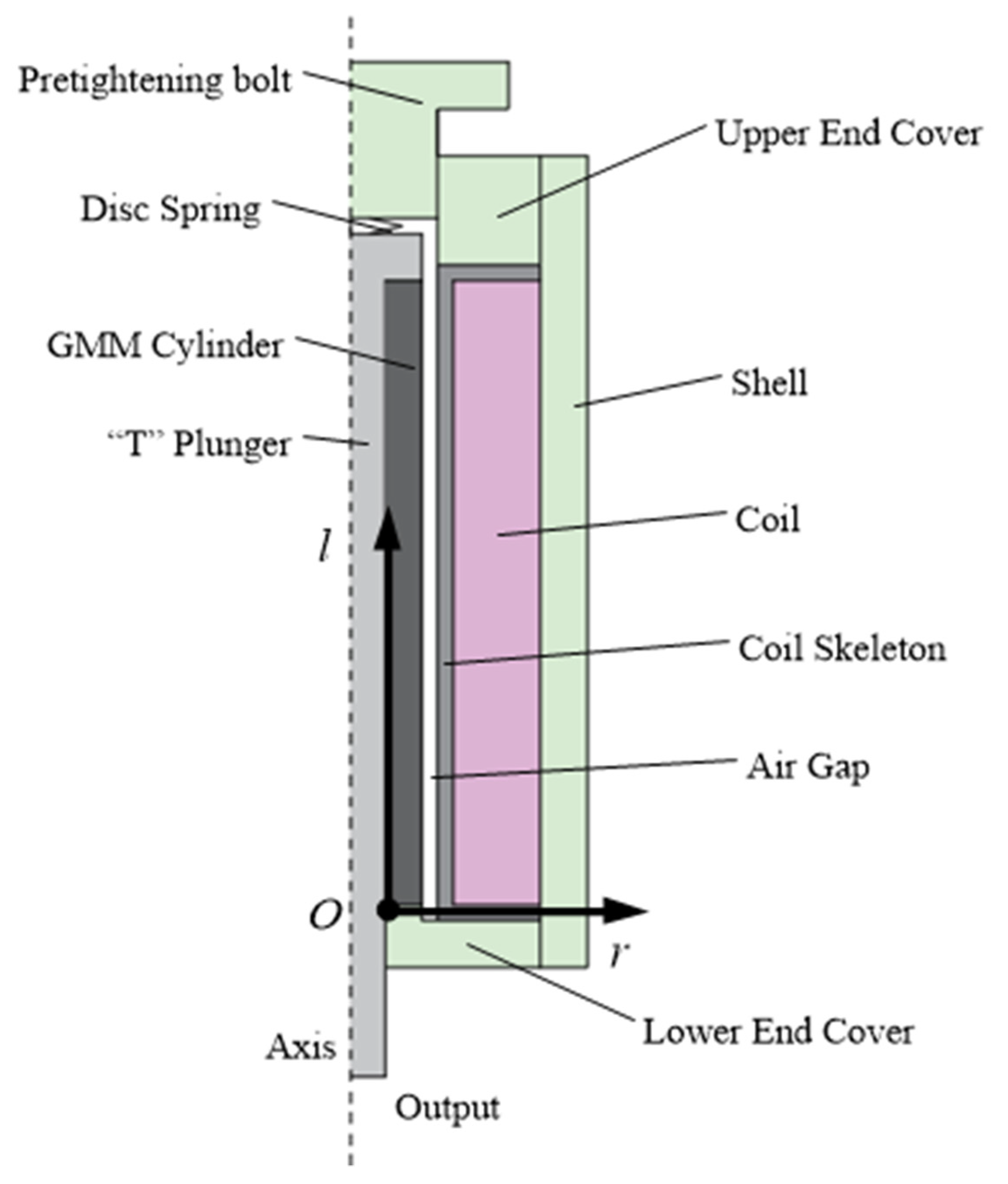
Figure 1. Schematic diagram of the structure of the GMA device.
Actuators 11 00108 g001
Figure 2. Dimensions of some components of the actuator.
Actuators 11 00108 g002
Figure 3. GMA geometric model.
Actuators 11 00108 g003
Figure 4. Schematic diagram of GMA meshing.
Actuators 11 00108 g004
Figure 5. Schematic diagram of GMA magnetic field distribution.
Actuators 11 00108 g005
Figure 6. Establishment of coordinate system.
Actuators 11 00108 g006
Figure 7. (a) The magnetic field intensity on an axis of the cylinder taken as the research object; (b) the magnetic field intensity of a section on the cylinder taken as the research object.
Actuators 11 00108 g007
Figure 8. Radial magnetic field distribution of the cylinder section at 50% of the total length of the GMM cylinder.
Actuators 11 00108 g008
Figure 9. Regional division.
Actuators 11 00108 g009
Figure 10. The axial magnetic density distribution of the GMM cylinder by changing the relative permeability of the displacement conversion mechanism. (a) ur=1, 5, 10, 20, 40, 100, (b) ur=100, 200, 500, 1000, 2000.
Actuators 11 00108 g010
Figure 11. Change in magnetic density of GMM cylinder by changing the relative permeability of the displacement conversion mechanism.
Actuators 11 00108 g011
Figure 12. Influence of relative permeability of displacement conversion mechanism on deviation of axial magnetic density of GMM cylinder.
Actuators 11 00108 g012
Figure 13. The axial magnetic density distribution of the GMM cylinder by changing the relative permeability of the shell. (a) ur=1, 5, 10, 20, 40, 100, (b) ur=100, 200, 500, 1000, 2000.
Actuators 11 00108 g013
Figure 14. Changes in the magnetic density of the GMM cylinder by changing the relative permeability of the shell.
Actuators 11 00108 g014
Figure 15. Influence of relative permeability of shell on deviation of axial magnetic density of GMM cylinder.
Actuators 11 00108 g015
Figure 16. The axial magnetic density distribution of the GMM cylinder by changing the air gap size.
Actuators 11 00108 g016
Figure 17. Change in magnetic density on GMM cylinder with changing air gap size.
Actuators 11 00108 g017
Figure 18. Influence of air gap size on deviation of axial magnetic density of GMM cylinder.
Actuators 11 00108 g018
Figure 19. Magnetic field intensity testing system.
Actuators 11 00108 g019
Figure 20. GMA physical drawing. (a) GMA device overall drawing, (b) GMA device exploded view.
Actuators 11 00108 g020
Figure 21. Magnetic field intensity measuring point.
Actuators 11 00108 g021
Figure 22. Schematic diagram of experiment operation.
Actuators 11 00108 g022
Figure 23. Comparison of magnetic field intensity between simulation and experiment: (a) Z = 0 mm; (b) Z = 10 mm; (c) Z = 20 mm; (d) Z = 30 mm; (e) Z = 40 mm; (f) Z varied from 0 mm to 40 mm.
Actuators 11 00108 g023
Table 1. Actuator material properties.
NO.Structure NameMaterial ur
1Preload bolt2000
2Upper-end cover2000
3Disc spring
4Outer shell2000
5Excitation coil1
6Coil skeleton1
7Air gap1
8GMM cylinder20
9“T” plunger10
10Lower end cover2000
Publisher’s Note: MDPI stays neutral with regard to jurisdictional claims in published maps and institutional affiliations.

