Article

A Soft Self-Stable Actuator and Its Energy-Efficient Grasping

State Key Laboratory of Mechanical Transmission, University of Chongqing, Chongqing 400030, China
*
Author to whom correspondence should be addressed.
Actuators 2022, 11(4), 107; https://doi.org/10.3390/act11040107
Submission received: 28 February 2022 / Revised: 18 March 2022 / Accepted: 20 March 2022 / Published: 7 April 2022
(This article belongs to the Section Actuators for Robotics)

Abstract

:
Due to high compliance and adaptiveness, soft robots show more advantages than traditional rigid robots in grasping irregularly shaped or fragile objects. Moreover, soft robots attract increasing attention as more and more robots are adopted in unstructured or human–robot interaction environments. However, during the grasping process, most soft robots need constant input stimuli to maintain the grasping configurations, which directly induces low energy efficiency. This article demonstrates the self-stable property of the dual-chamber structure, which can maintain bending deformation without input stimuli based on the differential pressure of the two chambers. Based on the self-stable property, a soft self-stable actuator (SSSA) driven by the tendon is proposed, and it can maintain the bending deformation without energy consumption, which can improve the energy efficiency of the actuator significantly. The self-stability of the actuator during the restoring period is analyzed, and the energy consumption model of the actuator is developed. Finally, the experiments are conducted to verify the validity of the models. The results show the actuator can achieve self-stability without any energy input, and the energy consumption can be reduced by about 45%. Hence, the proposed actuator can be adopted in applications where energy efficiency is sensitive.

1. Introduction

Due to high compliance, fantastic adaptiveness, and safety, soft grippers show significant advantages over rigid grippers in grasping the object with fragility or uncertain shape, which is attracting more and more attention in the robot field [1,2,3]. The literature about soft functional materials, which can conduct actuation under external stimuli, actuator structure design, and grasp perception/control is widely reported [4,5,6,7].
The grippers based on soft pneumatic actuators (SPAs) show a great potential toward practical application due to its light weight [8,9,10], low manufacturing cost, and convenient control, and the SPA based on fiber-reinforcement was first proposed in [11,12]. However, the lower stiffness characteristics of the SPA based on fiber reinforcement limits its load capacity [13,14,15,16]. Cui et al. proposed a pneumatic gripper based on a structure with rigid and flexible combination, which can grasp various objects by adjusting its initial postures [17]. Zhang et al. proposed a gas–ribbon hybrid actuator in [18], which can manage a large weight of objects. Accordingly, the particle jamming technique was introduced to improve the stiffness of the SPAs, and the differential drive method was also presented to balance the stiffness and the dexterity of the actuator [19,20,21]. Wei et al. proposed a soft actuator with varied stiffness based on ball joint and particle jamming, which can be used where large stiffness is required [22]. However, the storage of particles affects the range of bending motions in some way [23]. Furthermore, due to the compressibility of gas, the inflation process is nonlinear, which increases the difficulties in precise deformation control, and the diffusion rate of the gas also limits the response rate of the SPAs [24,25]. Based on the tendon-driven method, Lee et al. proposed a compliant actuator to mimic the human wrist by utilizing the tensegrity structure [26]. Fang et al. presented a soft gripper to achieve motion control to satisfy various grasping tasks without a compressed air source [27]. Moreover, compared with the SPAs, the tendon-driven soft actuators (TSAs) can achieve stiffness modulation and more precise motion control [28,29,30,31].
Unfortunately, the energy efficiency of these soft robots is even lower than 0.1 % , because most SPAs or TSAs need continuous energy supply to maintain the desired deformation [32,33]. Correspondingly, Ren et al. proposed a soft self-pumping actuator (SSPA) to reduce energy consumption attributing to drive force reduction of the tendon [34]. Nevertheless, the SSPAs also need continuous input force to maintain the grasping configurations, which constrains the further improvement of the energy efficiency [35,36,37,38]. Furthermore, the soft robots cannot save energy by motion planning as rigid robots can due to the preprogrammed structure [39,40].
In the view of the low energy efficiency of soft robots, a soft tendon-driven self-stable actuator featuring a dual-chamber structure is proposed in this article. The two chambers are pre-charged with desired pressure of air to increase self-stiffness. A tube with a valve connects the two chambers, one of which is filled with particles, as shown in Figure 1A. Under the tendon pulling force F p , the actuator will bend toward the particle chamber; correspondingly, the volume of the particle chamber is compressed. Since the two chambers are connected, the air of the particle chamber is pumped into the air chamber through the air channel to reach pressure equilibrium. It would facilitate the bending process of the actuator, which is called the self-pumping effect, as shown in Figure 1B. Once the valve is closed and the tendon is released, the internal stretch of the hyperelastic material induces the restoring of the actuator, as shown in Figure 1C. Due to the two chambers not allowing air flow to each other, the air chamber is compressed while the particle chamber expands during the restoring period, which contributes to the differential pressure between the two chambers. Hence, the differential pressure results in two effects: First, the differential pressure increases the torque against restoring. Second, the differential pressure causes the particles to jam each other, which stiffens the proposed actuator. Moreover, both of the effects constrain the further restoring deformation. As a result, the actuator can achieve the equilibrium after a certain restoring angle; namely, the actuator can maintain the bending configuration without any input force, and the proposed actuator does not consume energy during the self-stable period.

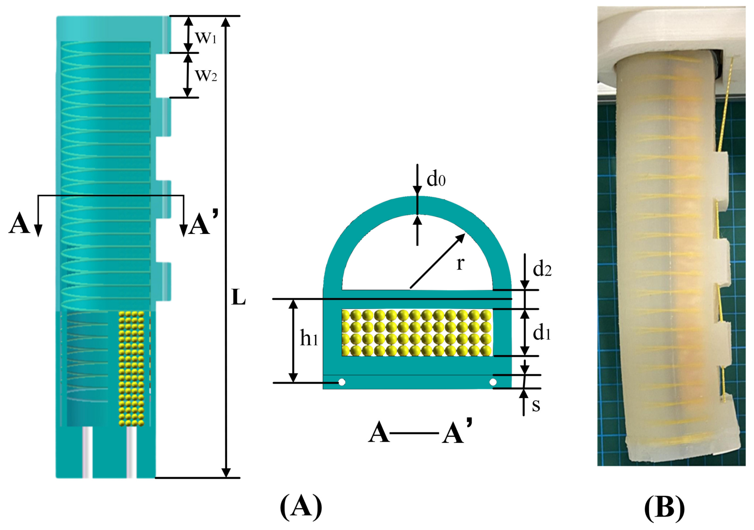
2. Actuator Structure

The structural parameters and fabrication process of the proposed actuator are discussed in this part. A dual-chamber actuator with a hemicircle cross-section air chamber and a rectangular cross-section particle chamber is adopted. The length and the outer wall thickness of the dual-chamber structure are L and d 0 , respectively. The inner radius of the air chamber is r, while the inner height of the particle chamber is d 1 . The thickness of the inner wall between the two chambers is d 2 , and a strain-limiting layer is placed in the middle of the inner wall between the particle chamber and the air chamber. Tendon guides are designed on the bottom, whose thickness and length are s and w 1 , respectively, and the distance between the tendon guides and the strain-limiting layer is h 1 . Furthermore, the two chambers are connected by a air channel (two small tubes and a valve), as shown in Figure 2A.
The actuator is fabricated as follows: First, the shapes of the two chambers were defined by 3D-printed rectangular and semicircular rods, and a polyethylene clothing the strain-limiting layer was put between the two rods. Second, the silicone rubber (EON-20, Shenzhen Yi-Heng Fine Chemical Co., Ltd., Shenzhen, China) was cured inside the mold to form the inner layer of the actuator. When the inner layer had solidified, a double helix reinforcement fiber (nylon, 0.38 mm diameter) was wound around in our preset track. Another outer layer of silicone rubber was cured to combined the dual-chamber, and the tendon guide parts were simultaneously built. In addition, particles were filled into one chamber before the two chambers were sealed. Finally, a vented duct was mounted on the proximal end cap, and a tube with check-valve was connected to the vented duct for pre-charging, as shown in Figure 2B.

3. Modeling

The modeling part is organized as follows. First, Section 3.1 focuses primarily on the variation of chamber pressure. Then, the torque analysis and the torque equilibrium analysis are detailed in Section 3.2 and Section 3.3. Furthermore, the analysis of energy consumption will be introduced in Section 3.4. To model the actuator’s behavior, several assumptions are made first as follows:
  • The radial expansion of the actuator is ignored contributing to the constrain fibers;
  • The friction between the tendon and the actuator is ignored;
  • The elongation of the tendon is ignored, and the tension force along the tendon direction is equal everywhere;
  • The tendon is pulled with uniform velocity during the bending period.
Since any motion of the actuator is confined to a plane, a plane coordinate is introduced, as shown in Figure 3. The origin O is set at the bottom of the actuator while the Y axis is defined along the axial direction of the actuator at the initial state.

3.1. Pressure Variation

In the process of bending and restoring, the change of chamber gas pressure is very important. Thereby, the pressure variation of the actuator is analyzed first. The initial volume of the two chambers are defined as V A 0 and V B 0 , respectively:
V A 0 = π r 2 L 2 , V B 0 = 2 r d 1 L .
During the bending period, denote the tendon displacement and the center angle as x and 2 α , respectively. The actuator would bend toward the particle chamber with a radius R 1 , and the following relationship can be obtained according to Li [41]:
α = L 2 R 1 = x 2 h 1 .
According to the assumptions, there is no circumferential strain. Assume the actuator reaches bending angle α , the corresponding volumes of the two chambers are defined as V A and V B , respectively, which can be formulated as:
V A = 4 α 0 π 2 R 1 + r sin θ r 2 cos θ d θ ,
V B = α π π R 1 d 2 2 2 π R 1 d 2 2 d 1 2 · 2 r d 1 .
During the bending process, the valve on the tube, which connects the two chambers, is open. Since the actuator is sealed after being pre-charged, the air in the two chambers can be considered as the ideal gas, and the pressure in both chambers is the same. Denote the pre-charged pressure as P I , and the pressure of two chambers can be obtained according to the ideal gas state equation as:
P A = P B = P I ( V A 0 + V B 0 ) V A + V B .
By closing the valve and releasing the tendon when the actuator reaches the bending angle α , the actuator restores and would finally achieve an equilibrium after restoring δ , as shown in Figure 3. Define the radius with respect to the strain-limiting layer as R 2 , there exists:
R 2 = L 2 ( α δ ) .
The volume of the two chambers after restoring can be formulated as:
V A = 4 α δ 0 π 2 R 1 + r sin θ r 2 cos θ d θ ,
V B = α δ π π R 2 d 2 2 2 π R 2 d 2 2 d 1 2 · 2 r d 1 .
The restoring process results in the increase of particle chamber volume and the decrease of the air chamber. Consequently, the pressure of the two chambers changes. Since there is no air flow between the two chambers, the pressure of the two chambers can be obtained based on the ideal gas state equation as:
P A = P A V A V A , P B = P B V B V B .
Accordingly, the differential pressure between the two chambers can be calculated as:
P d = P A P B .

3.2. Torque Analysis

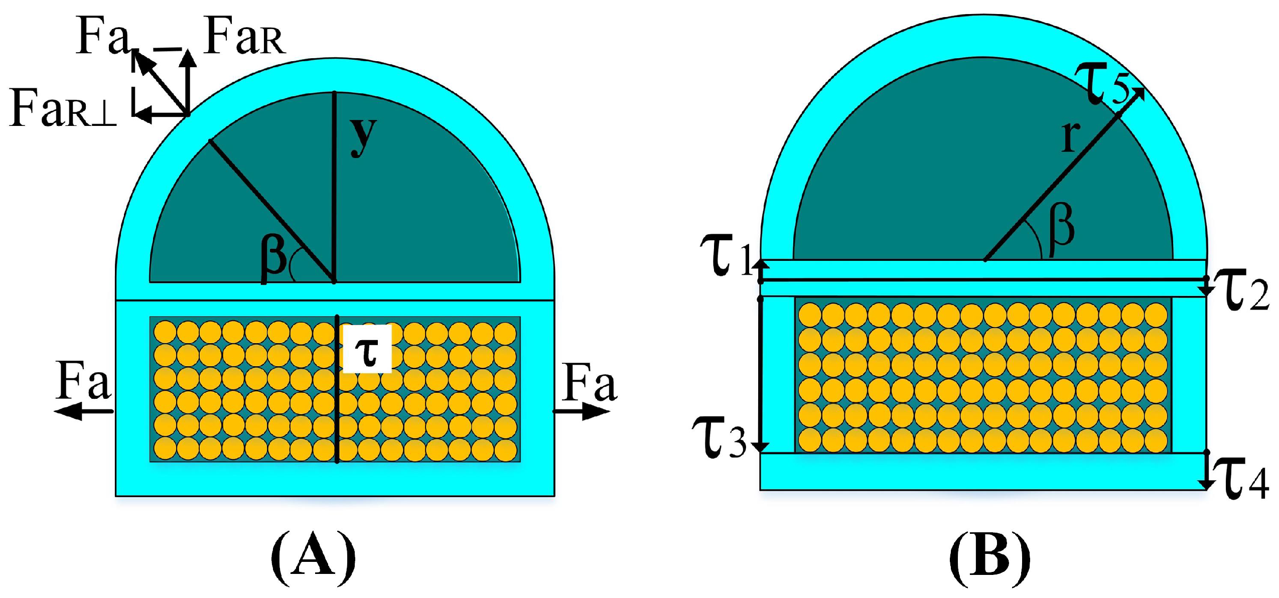
3.2.1. Torque of Particle Jamming

The particle jamming torque is discussed as follows. The particles in the particle chamber and the inner wall of the particle chamber will press against each other when there is a differential pressure between the two chambers. According to Wei [22], the compressing force can be obtained by multiplying the differential pressure and the contact area based on Pascal’s principle. To calculate the torque caused by the friction between the particles and the bottom wall of the chamber, a narrow strip rectangular differential element Δ S whose length and width are defined as 2 r and L 2 α d 2 / 2 d 1 d ϑ , respectively, is introduced first. ϑ is the corresponding center angle, as shown in Figure 3. The normal force generated by the differential pressure on the element of the particle chamber’s inner wall can be expressed as:
f n = 2 r P d L 2 α d 2 / 2 d 1 d ϑ ,
and the the friction between the particles and the chamber inner wall is f = μ f n , where μ is the friction coefficient between the particles and the chamber inner wall. Accordingly, the fiction f can be separated into two parts: X-component f sin ϑ and Y-component f cos ϑ , and the force arms along the direction of X and Y are defined as L X and L Y , respectively. The force arm in the X-direction of the fiction f can calculated as:
L X = L 2 α d 2 / 2 d 1 sin ϑ ,
In the same way, the force arm in the Y-direction of the fiction f can expressed as:
L Y = L 2 α L 2 α d 2 2 d 1 cos ϑ ,
Thus, the corresponding torque can be calculated:
M p 1 = μ P d 0 2 α 2 r L 2 α d 2 2 d 1 2 sin 2 ϑ 2 r L 2 α d 2 2 d 1 L 2 α L 2 α d 2 2 d 1 cos ϑ ) cos ϑ d ϑ ,
In the same way, the torque caused by the friction on the upper internal wall and the side wall of the particle chamber, which are denoted as M p 2 and M p 3 , respectively, can be calculated as:
M p 2 = μ P d 0 2 α 2 r L 2 α d 2 2 2 sin 2 ϑ 2 r L 2 α d 2 2 L 2 α L 2 α d 2 2 cos ϑ cos ϑ d ϑ ,
M p 3 = μ P d π 0 2 α L 2 α d 2 2 2 L 2 α d 2 2 d 1 2 L 2 α d 2 2 d 1 2 sin 2 ϑ L 2 α L 2 α d 2 2 d 1 2 cos ϑ ) cos ϑ ) d ϑ .
Accordingly, the combined particle jamming torque can be formulated as:
M p ( α δ , P d ) = M p 1 + M p 2 + 2 M p 3 .

3.2.2. Torque of Air Pressure

The torque due to air pressure can be calculated in the same way as the common single-chambered soft fiber-reinforced actuator [42]. Therefore, the torque generated by internal air pressure at the internal bottom surface of the particle chamber can be calculated as:
M a 1 = 2 r ( P A P a t m ) 0 2 α L 2 α d 2 2 d 1 2 sin ϑ cos ϑ L 2 α d 2 2 d 1 L 2 α L 2 α d 2 2 d 1 cos ϑ sin ϑ d ϑ ,
where P a t m is the atmospheric pressure.
The orientation of the force caused by internal air pressure on the side layer of the particle chamber is perpendicular of the XOY plane, which is parallel to the rotation axis. Consequently, it does not contribute to the bending effects of the actuator.
The force analysis of the top semicircular layer of the air chamber is shown in Figure 4A. Force F a 2 on the top semicircular layer can be decomposed into F a 2 R and F a 2 R . F a 2 R is similar to the force analysis on the side wall of the particle chamber. Therefore, the component F a 2 R does not contribute to the bending effects of the actuator. Meanwhile, F a 2 R can be decomposed into an X-component and Y-component for calculation. The local coordinate β , as shown in Figure 4, is introduced to calculated the torque generated by internal air pressure on the top semicircular layer of the air chamber, and there exists:
M a 2 = r ( P A P a t m ) 0 2 α 0 π L 2 α + d 2 2 + r sin β 2 sin β sin ϑ cos ϑ L 2 α + d 2 2 + r sin β L 2 α L 2 α + d 2 2 + r sin β cos ϑ sin β sin ϑ d β d ϑ .
Similarly, the force caused by the internal pressure at the distal cap can be decomposed into an X-component and Y-component. Meanwhile, the local coordinate y and τ , as shown in Figure 4A, are presented to calculated the corresponding torque:
M a 3 = 2 r 2 y 2 ( P A P a t m ) 0 r L 2 α + d 2 2 + y sin 2 2 α L 2 α L 2 α + d 2 2 + y cos α cos α d y + 2 r ( P B P a t m ) 0 d 1 L 2 α d 2 2 d 1 + τ sin 2 2 α L 2 α L 2 α d 2 2 d 1 + τ cos α cos α d τ .
Accordingly, the combined air pressure torque can be expressed as:
M a ( α , P A ) = M a 1 + M a 2 + M a 3 .

3.2.3. Torque of Elastic Stress

Compared with the stretch of the bottom wall, the tendon guide parts are small, and the corresponding elastic stresses can be ignored. The torque of the elastic stresses is mainly caused by the axial stress, which contains the torques of the internal stress in the top hemicircular wall, the side walls, the inner wall, and the bottom wall. Meanwhile, the inner wall is separated by the strain-limiting layer, and the upper part is stretched while the lower part is compressed. Referring to Wang [43], local coordinates τ 1 , τ 2 , τ 3 , τ 4 , and τ 5 are defined to model the torque caused by the corresponding stress of the actuator, as shown in Figure 4B. Thus, the longitudinal stretch of the five parts can be calculated as follows.
λ τ 1 = R 1 + τ 1 R 1 , λ τ 2 = R 1 τ 2 R 1 , λ τ 3 = R 1 d 2 / 2 τ 3 R 1 , λ τ 4 = R 1 d 2 / 2 d 1 τ 4 R 1 , λ τ 5 = R 1 + d 2 / 2 + ( r + τ 5 ) sin β R 1 .
where λ τ 1 , λ τ 2 , λ τ 3 , λ τ 4 , and λ τ 5 are longitudinal stretches of the bottom wall, the side wall, the upper inner wall, the lower inner wall, and the top hemicircle wall, respectively. Accordingly, the corresponding stresses can be calculated as:
s i = ν ( λ τ i 1 λ τ i 3 ) , i = 1 , , 5 ,
where ν is the initial shear modulus of the material, and s i is the corresponding stress variable. Therefore, the torque caused by the internal stresses of the material of each part can be calculated as:
M e 1 = 0 d 2 / 2 s 1 ( 2 r + 2 d 0 ) L τ 1 d τ 1 ,
M e 2 = 0 d 2 / 2 s 2 ( 2 r + 2 d 0 ) L τ 2 d τ 2 ,
M e 3 = 0 d 1 s 3 2 d 0 L ( d 2 / 2 + τ 3 ) d τ 3 ,
M e 4 = 0 d 0 s 4 ( 2 r + 2 d 0 ) L ( d 2 / 2 + d 1 + τ 4 ) d τ 4 ,
M e 5 = 0 d 0 0 π s 5 ( r + τ 5 ) L ( d 2 / 2 + ( r + τ 5 ) sin β ) d β d τ 5 .
Furthermore, the corresponding combined torque can be expressed as:
M e = M e 1 + M e 2 + M e 3 + M e 4 + M e 5 .

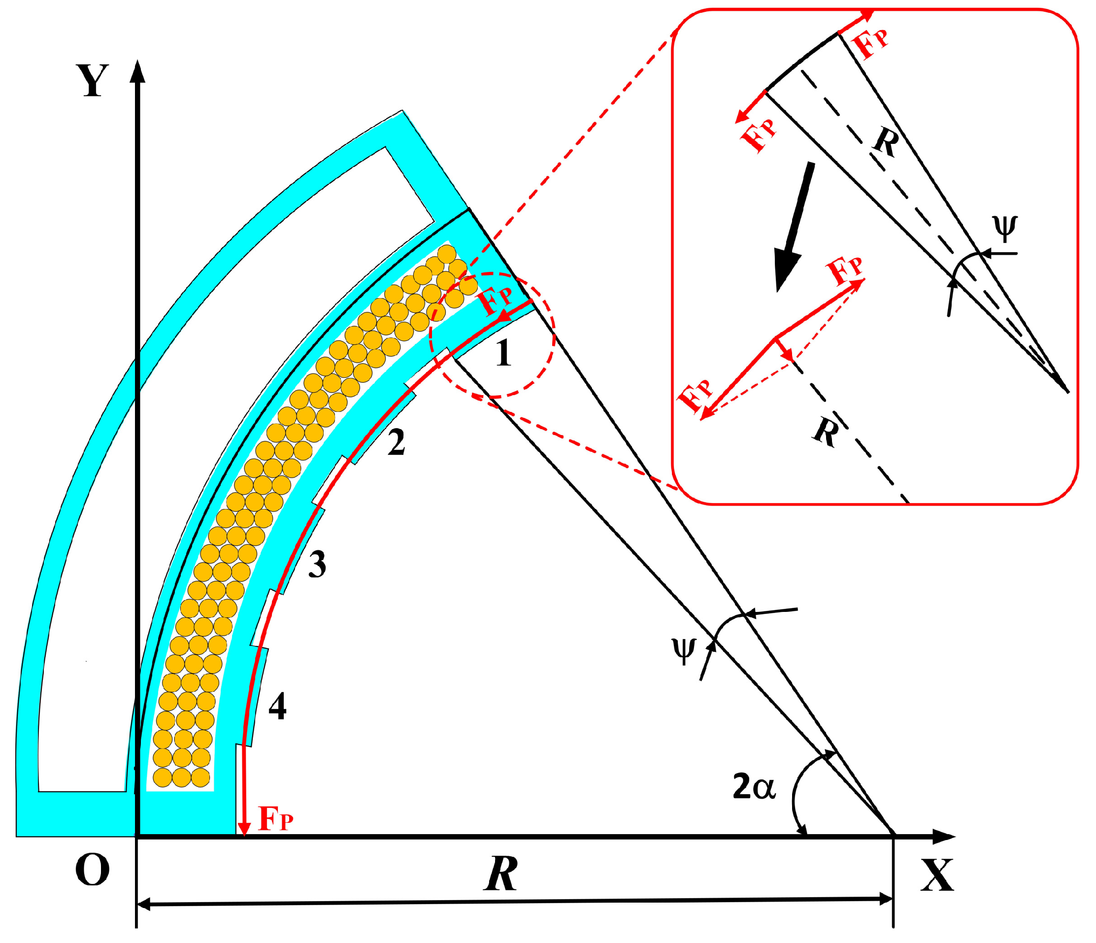
3.3. Torque Equilibrium of the Actuator

Note that there exists an external force on the actuator when the actuator is adopted in grasping. Assume the external force is along the X direction, as shown in Figure 3 in red, whose value is denoted as F. Accordingly, the torque caused by the external force around O can be formulated as:
M F = F L 2 α d 2 / 2 d 1 d 0 sin 2 α .
Assume the actuator can achieve a self-stable state after a restoring angle δ without the input tendon pulling force F P . Subsequently, the self-stable behavior of the proposed actuator under load is verified, and the torque equilibrium during the restoring period is analyzed. The self-stable state is the combining result of torque caused by air pressure M a , the torque caused by elastic stress M e , the torque caused by the particle jamming M p , and the torque caused by the external force M F . Based on the torque analysis above, the torque equilibrium with respect to the origin O can be formulated as:
M F ( α δ ) , F + M e α δ = M p α δ , P d + M a α δ , P A .
When design parameters d 0 , d 1 , d 2 , h 1 , r, and L are given, the torque due to external force M F is only related to the bending angle α , restoring angle δ , and the value of the force F. M p is related to the bending angle α , the restoring angle δ , and the pressure difference of two chambers P d according to Equation (10). Meanwhile, M a is related to the bending angle α , the restoring angle δ , and the restoring pressure of air chamber P A . Moreover, M e is only related to the bending angle α and the restoring angle δ . However, the tendon displacement x determines the bending angle α based on Equation (2). Based on Section 3.1, the pressure of the air chamber after restoring P A and the differential pressure P d are determined, once the bending angle α , the restoring angle δ , and the pre-charged pressure P I are given. Accordingly, when the pre-charged pressure P I , the tendon displacement x, and the external force F are determined, Equation (31) is just an equation of the restoring angle δ , and there always exists the solution. However, the integrals from Equation (28) cannot be computed analytically, and as a result, Equation (31) is a transcendental equation. Thus, the restoring angle δ can only be numerically obtained.

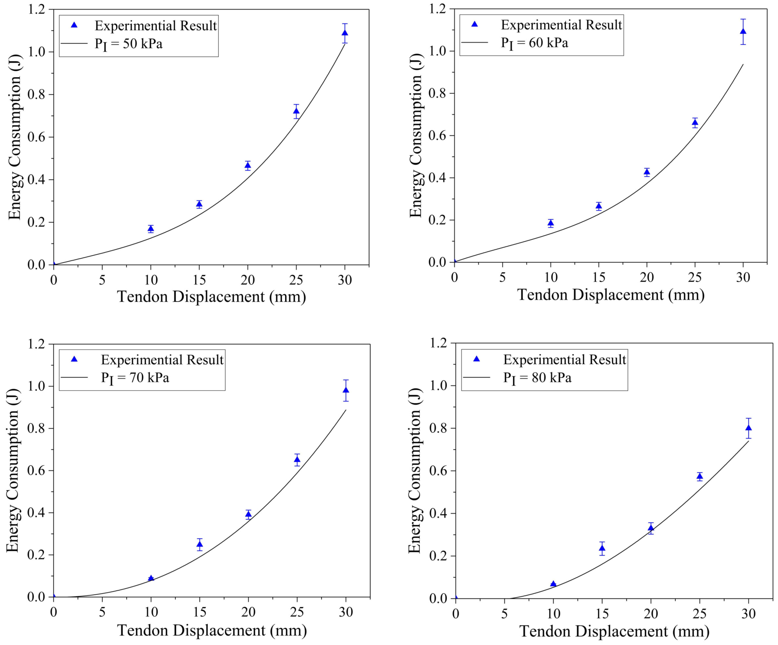
3.4. Analysis of Energy Consumption

The work of the tendon pulling force during the bending period determines the energy consumption of the SSSA. According to Assumption 4, the tendon only contacts the tendon guides and the distal cap of the SSSA. Take the first tendon guide for analysis, the resultant of the tendon pulling force must be along its corresponding angle center line, and the corresponding angle is defined as ψ , as shown in Figure 5. Accordingly, the resultant of the tendon pulling force F p r can be formulated as:
F p r = 2 F p sin ψ 2 ,
where ψ = ( w 1 x ) / L x h 1 . F p r can be decomposed into an X-component and Y-component. Therefore, the torque due to the resultant force F p r of the first tendon guide part can be calculated as:
M F p r 1 α = F p r L 2 α h 1 sin α 1 cos α 1 + F p r L 2 α L 2 α h 1 cos α 1 sin α 1 ,
where α 1 = 2 α L x w 1 / 2 / ( L x ) . The torque due to the resultant force F p r on the other tendon guide parts can be calculated same as the first tendon guide part; therefore, the total torque caused by all the tendon guides can be expressed as:
M F p r α = i = 1 4 M F p r i = F p L r α ,
where L r α = 2 L 2 α h 1 sin α i cos α i sin ψ 2 + 2 L 2 α L 2 α h 1 cos α i sin α i sin ψ 2 , i denotes the index of the tendon guide part, α i = L x 2 i 1 w 1 / 2 i 1 w 1 / ( L x ) , i = 1 , , 4 .
The torque due to the tendon pulling force at the distal cap M F d can be obtained based on force decomposition as:
M F d α = F p L d α ,
where L d α = L 2 α h 1 sin 2 2 α + L 2 α L 2 α h 1 cos 2 α cos 2 α .
Accordingly, the torque caused by the tendon pulling force can be expressed as:
M F p α = M F d α + M F p r α .
According to Assumption 4, the bending state is the combined result of the torque due to air pressure M a , the torque due to elastic stress M e , the torque due to the tendon pulling force M F p , and the torque due to the external force M F . The torque equilibrium with respect to the origin O can be formulated as:
M e α + M F α = M a α , P A + M F p α .
Based on the torque equilibrium (37), the tendon pulling force can be expressed as:
F p = M e α + M F α M a α , P A L r α + L d α
Consider the bending angle changes d ϑ due to pulling the tendon, and the corresponding tendon displacement is 2 h 1 d ϑ . Assume the tendon pulling force remains constant during the small deformation, and the energy consumed to reach bending angle α can be formulated as:
E = 2 0 2 α M e ϑ + M F ϑ M a ϑ , P A L r ϑ + L d ϑ h 1 d ϑ
Provided that the P A and design parameters, such as L, h 1 , d 0 , d 1 , and d 2 are given, Equation (38) is an equation of F p . However, the integral in (28) is a hyperanalytic equation. Thus, F p only has a numerical solution. Consequently, the energy consumption (39) can only be obtained by numerical algorithms.

4. Experiments

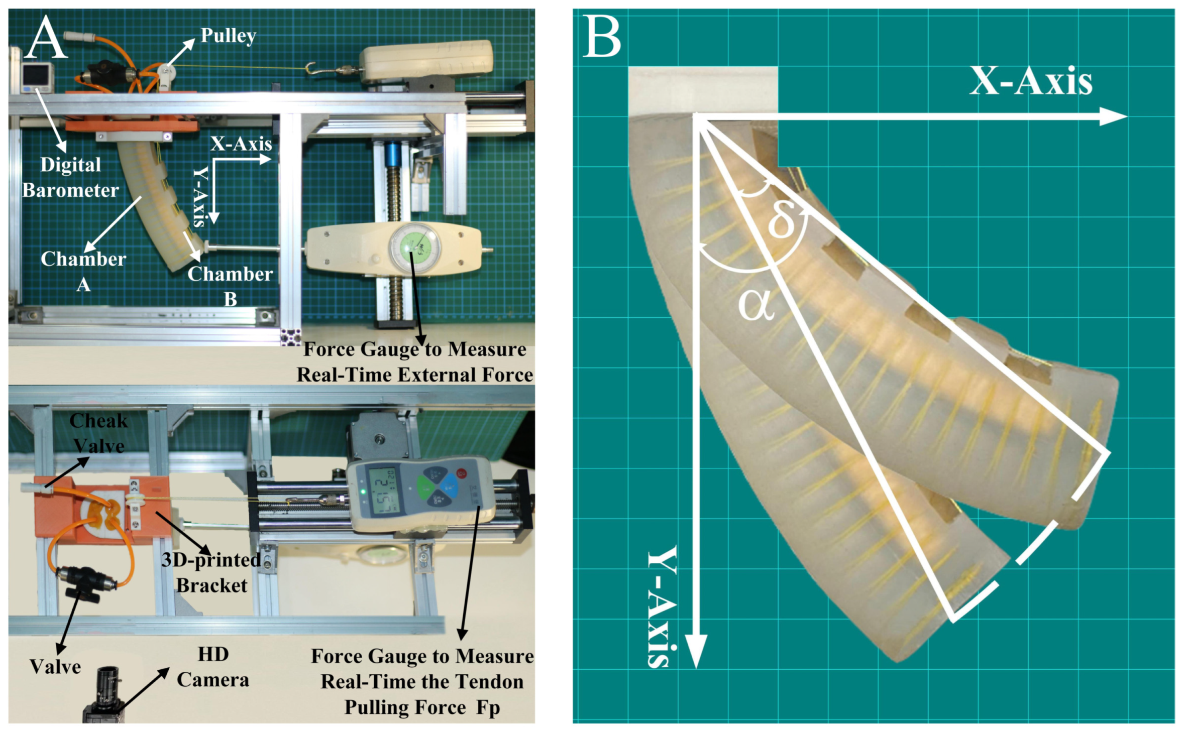
4.1. Experimental Environment

The experimental platform was set up, as shown in Figure 6A. The proposed actuator was mounted on a 3D-printed basement. The basement and other mountings were printed by an A8 FDM commercial three-dimensional printer (Shenzhen Aurora Technology Co., Ltd., Shenzhen, China). The tendon was connected to a linear guide-way through a pulley, which can provide precise control of the tendon length. Moreover, a digital barometer (from LUBOSHI Co., Ltd., Shenzhen, China) was connected to the valve to detect the pressure variation of the chamber, a force gauge was used to provide and detect forces in real time, and another force gauge was used to measure the real-time the tendon pulling force; both force gauges were produced by (HANDPI Co., Ltd., Zhejiang, China) A high-resolution camera from (Shenzhen Lantian Technology Co., Ltd., Shenzhen, China) was also adopted to capture the motion of the actuator. The software Kinovea was also used to measure the variation of the bending angle, as shown in Figure 6B.

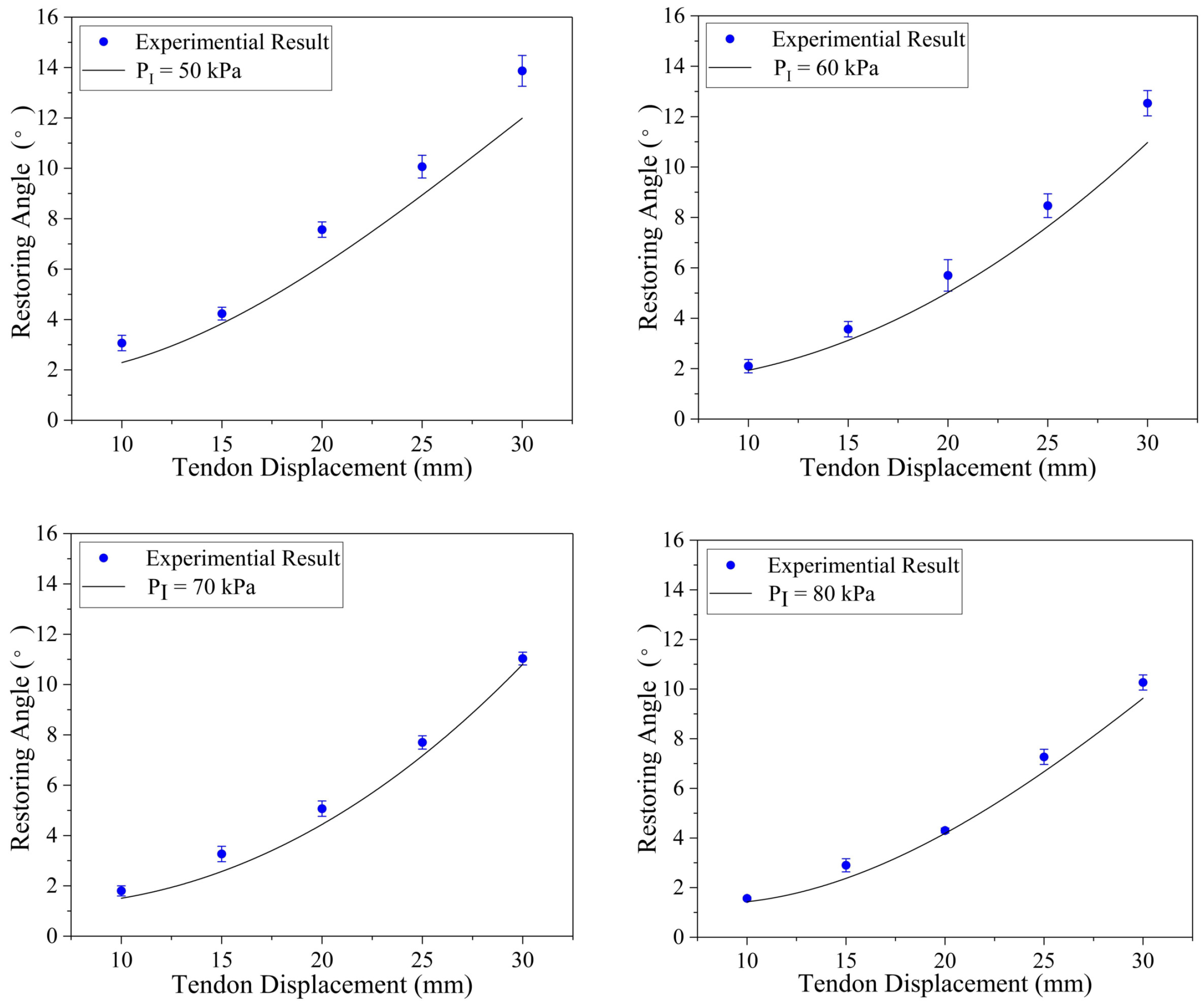
4.2. Model Verification

To explore the self-stable property of the proposed actuator, we pre-charged the initial chamber pressure of the actuator range from 50 to 80 kPa at a interval of 10 kPa, and the structure parameters of the proposed actuator were d 0 = 4 mm, d 1 = 10 mm, d 2 = 4 mm, r = 16 mm, and L = 140 mm. Then, the actuator was driven by the tendon displacement from 10 to 30 mm. According to the video captured by the camera, the actuator can successfully achieve a self-stable state after releasing the tendon. The variation of the bending angles was shown in Figure 7, which shows that the restoring angle δ increases as the tendon displacement x increases, and the restoring angle δ decreases as the initial pre-charged pressure P I increases. According to the results, the proposed model can effectively predict the restoring angle. Moreover, the experimental results are close to the theoretical ones, which indicates the validity of our model. However, the experimental value is higher than the theoretical value. The reason for this phenomenon is that the internal stretch tendon guide part and the tension of strain-limiting layer are ignored, and the internal stretch tendon guide part and the tension of the strain-limiting layer produce additional torque for the restoring of the SSSA.
To test the theoretical model of energy consumption, the power of the stepper motors were measured by a Sentron PAC3200 multifunctional measuring instrument (Siemens Co., Ltd., Berlin, Germany), and the stepper motors are used to pull the tendon. Theoretical modeling of the proposed actuator’s energy consumption has been validated, and the related experimental results are shown in Figure 8. The energy consumption E decreases with the increase of pre-charged pressure P I . It can be explained as that the torque of the air pressure and the torque caused by the tendon pulling force lead to the bending motion, namely, the initial pre-charged pressure P I would facilitate the bending process of the proposed actuator. Meanwhile, the proposed theoretic model can effectively predict energy consumption during the bending period. However, the computational results are smaller than the experimental results. The reason for this phenomenon is that only the tendon contact on the distal cap and the tendon guides are considered. In addition, pulling the tendon with the uniform and small velocity is an ideal condition. Therefore, the value of the actual pulling force is larger than the force obtained in (38); accordingly, the actual energy consumption is larger than the theoretical value.

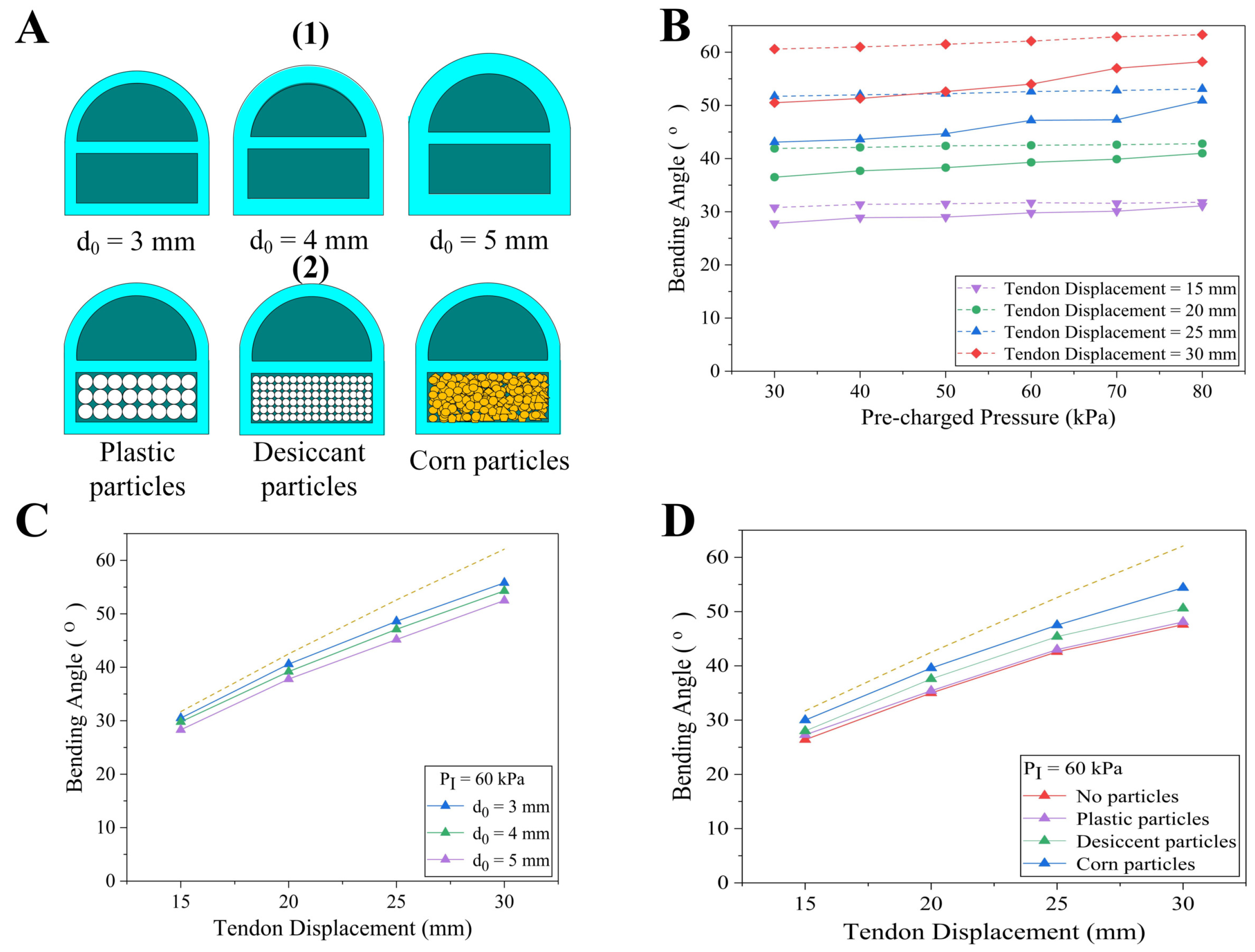
4.3. Influence Factors

In addition to the tendon displacement, the design parameters, such as pre-charged pressure, particle thickness, and layer thickness, also have influences on the restoring angle. It is worth mentioning that the dotted line in Figure 9 represents the bending angle before restoring, and the thickness of the layer separating the jamming particle chamber and air chamber d 2 is same in all our experiments. First, we conducted the first group experiments to evaluate the influences of the pre-charged pressure. The actuator was pre-charged at 10 KPa intervals from 30 to 80 KPa at pressure, which has the same structure parameters and particles as the one used in the model validation experiment. The variation of the bending angle after tendon release is plotted in Figure 9B. It can be observed that the restoring angle decreases as the pre-charged pressure rises on the condition that the tendon displacement is given. The reason for this deviation is that the larger pre-charged pressure contributes to the larger differential pressure between the two chambers at the same restoring angle during the restoring process. According to the analysis in Section 3.2.1, the increase of the pressure difference between the two chambers leads to the increase of particle jamming torque and air pressure torque. Therefore, the restoring angle decreases according to the torque equilibrium in Section 3.3. In addition, assuming the pre-charged pressure is given, the restoring angle has a positive correlation with the tendon displacement. This is because that large tendon displacement results in the increase of the initial bending angle α . As a result, the torque due to elastic stress rises simultaneously, which causes further restoring of the actuator.
The second group of experiments was used to explored the effect of wall thickness on the actuator restoring angle. The wall thicknesses of the actuators were set ranging from 3 to 5 mm, while the other parameters and the particles were the same as the actuator adopted in the model validation experiment. The variation of the bending angle is shown in Figure 9C. The result reveals that the restoring angle also has a positive correlation with the wall thickness. This phenomenon can be illustrated as a thick wall that directly increases the torque due to elastic stress, and the restoring angle increases.
In the meantime, to explore the effect of particles on the actuator restoring angle, a series of particles were filled into the actuator adopted in the model validation experiment, as shown in Figure 9D. The actuator without particles, which is similar to the SSPA proposed in [34], was also used for comparison. All actuators were pre-charged at air pressure of 60 KPa, and the experimental resultsreveal that the differences of particles do not effect the trend of restoring angles with tendon displacement. Compared with the actuator without particles, the particles can reduce the restoring angle significantly. It is worth noting that the restoring angle of the actuator with corn particles is only one-fourth of the actuator without particles when the tendon displacement is small. The restoring angles of the actuators with plastic spherical particles are larger than the actuator with corn ones and desiccant ones, which is attributed to the friction coefficient differences and regularity of particles. The surface roughness of corn particles and desiccant particles are much larger than that of the plastic spherical particles, while the corn particles are more irregular than the desiccant particles. Accordingly, the torque due to the particles jamming of the actuator with corn particles is larger than the others, which leads to the smallest restoring angle.
According to the three groups of experiments, it can be found that a larger pre-charge pressure, thin wall structure, irregular shape, and large roughness of particles contribute to the small restoring angle of the actuator, which can be considered as the guideline to design an SSSA with high performance.

4.4. Grasping Demonstration

To verify the grasping performance, three SSSAs with 3 mm wall thickness filled with corn particles were pre-charged at air pressure of 80 KPa, which were designed according to the guideline. Then, the three actuators were assembled into a gripper, which is shown in the video attachment. Three stepper motors (model 42BYGH39-401A), which were produced by PUFEIDE Co., Ltd., Chendu, China connect with the tendons to drive the corresponding SSSA. Figure 10A,B demonstrates the grasping of a cup, a lemon, which verifies the good adaptivity and flexibility for both irregular and fragile objects. Since there still exists a small restoring angle, the gripper based on SSSAs is more suitable for objects with an elastic or soft body.
To test the energy consumption of the SSSA, both grippers based on an SSPA and the gripper based on an SSSA with the same design parameters and pre-charge pressure conducted the grasping motion, and a Sentron PAC3200 was adopted to measure the power of the stepper motors. Both grippers were driven by the stepper motors to reach the same grasping configuration to grasp the same loads from 100 to 600 g, and we maintained the grasping configuration to hold the loads. To capture the power variation, both the grasping and holding periods were set for 20 s. The gripper based on the SSPA and SSSA grasped the load of 300 g weight, as shown in Figure 10C, and the power curves of two grippers are shown in Figure 10D,E. During the grasping period, the power curve of both grippers is similar, and the gripper based on the SSSA is slightly larger than the gripper based on the SSPA. This is because the particles contribute to the resistance to bending of the actuator. In the holding period, the gripper based on the SSPA constantly consumed energy to maintain the grasping configuration, while the gripper based on the SSSA did not consume any energy due to the self-stable property. Both grippers grasped loads from 100 to 600 g three times, and the average energy consumption is shown in Figure 10F. The gripper based on the SSSA costs about 45% less energy for the whole process, and the energy-saving effect would be more significant once the holding period lasts longer.

5. Conclusions

In this article, a soft self-stable actuator driven by a tendon was proposed, which only needs input stimulus to achieve the grasping configuration, and the actuator can maintain the grasping configuration without any energy consumption based on the self-stable property of the SSSA. The contributions of this article are summarized as the following. First, a soft self-stable gripper driven by a tendon was proposed based on the self-stability property, which can conduct high energy efficiency grasping compared with traditional grippers. Then, theoretical models were developed to forecast the behavior of the actuator during the self-stable state and the energy consumption during the bending period. Moreover, the influences of structure parameters, particles, and pre-charge pressure were analyzed, which can guide the design of the SSSA. Finally, we conducted several experiments to prove the validity of the proposed design and model. The proposed gripper can achieve low energy consumption grasping, which can provide an especial and fantastic alternative to energy-limited or energy-scarce environments.
However, it is worth noting that the restoring angle always exists, and it can even be reduced significantly by proper design once the self-stability is achieved based on the restoring of the actuator. Thus, the proposed actuator is more suitable for grasping soft or flexible objects rather than rigid objects, which is the main limitation of the proposed actuator. In future work, we will add sensors and feedback control to our fingers to resolve the problem with a restoring angle of the proposed actuator.

Author Contributions

Conceptualization, P.J. and X.L.; methodology, J.L., P.J. and X.L.; software, J.L.; validation, J.L., P.J. and X.L.; resources, P.J.; data curation, J.L. L.B., F.L. and R.C.; writing—original draft preparation, J.L., P.J. and X.L.; writing—review and editing, J.L.; supervision, P.J. All authors have read and agreed to the published version of the manuscript.

Funding

This research was funded in part by National Key R&D Program of China (No. 2018YFB1700602), the National Science Foundation of China (No.52075060, No. 52075051, No.51975070), the FundamentalResearch Funds for the Central Universities (No. 2020CDCGJX023), Technology Innovation and Application Project of Chongqing (cstc2018jszx-cyzdX0151).

Institutional Review Board Statement

Not applicable.

Informed Consent Statement

Not applicable.

Data Availability Statement

Data is contained within the article as figures and tables.

Conflicts of Interest

The authors declare no conflict of interest.

References

  1. Ni, X.; Liao, C.; Li, Y.; Zhang, Z.; Sun, M.; Chai, H.; Wu, H.; Jiang, S. Experimental study of multi-stable morphing structures actuated by pneumatic actuation. Int. J. Adv. Manuf. Technol. 2020, 108, 1203–1216. [Google Scholar] [CrossRef]
  2. Zhao, Y.; Shan, Y.; Zhang, J.; Guo, K.; Qi, L.; Han, L.; Yu, H. A soft continuum robot, with a large variable-stiffness range, based on jamming. Bioinspir. Biomim. 2019, 14, 066007. [Google Scholar] [CrossRef] [PubMed]
  3. Fitzgerald, S.G.; Delaney, G.W.; Howard, D. A Review of Jamming Actuation in Soft Robotics. Actuators 2020, 9, 104. [Google Scholar] [CrossRef]
  4. Wang, X.; Khara, A.; Chen, C. A soft pneumatic bistable reinforced actuator bioinspired by Venus Flytrap with enhanced grasping capability. Bioinspir. Biomim. 2020, 15, 056017. [Google Scholar] [CrossRef] [PubMed]
  5. Zheng, X.; Hou, N.; Dinjens, P.J.D.; Wang, R.; Dong, C.; Xie, G. A Thermoplastic Elastomer Belt Based Robotic Gripper. In Proceedings of the 2020 IEEE/RSJ International Conference on Intelligent Robots and Systems (IROS), Las Vegas, NV, USA, 24 October–24 January 2021; pp. 9275–9280. [Google Scholar]
  6. Chen, Y.; Chung, H.; Chen, B. A lobster-inspired articulated shaft for minimally invasive surgery. Robot. Auton. Syst. 2020, 131, 103599. [Google Scholar] [CrossRef]
  7. Chen, R.; Yuan, Z.; Guo, J.; Bai, L.; Zhu, X.; Liu, F.; Pu, H.; Xin, L.; Peng, Y.; Luo, J. Legless soft robots capable of rapid, continuous, and steered jumping. Nat. Commun. 2021, 12, 7028. [Google Scholar] [CrossRef]
  8. Li, H.; Yao, J.; Zhou, P.; Zhao, W.; Xu, Y.; Zhao, Y. Design and modeling of a high-load soft robotic gripper inspired by biological winding. Bioinspir. Biomim. 2020, 15, 026006. [Google Scholar] [CrossRef]
  9. Bilancia, P.; Berselli, G. Design and testing of a monolithic compliant constant force mechanism. Smart Mater. Struct. 2020, 29, 044001. [Google Scholar] [CrossRef]
  10. Chen, R.; Wu, L.; Sun, Y.; Chen, J.Q.; Guo, J.L. Variable stiffness soft pneumatic grippers augmented with active vacuum adhesion. Smart Mater. Struct. 2020, 29, 105028. [Google Scholar] [CrossRef]
  11. Bishop-Moser, J.; Krishnan, G.; Kim, C. Design of soft robotic actuators using fluid-filled fiber-reinforced elastomeric enclosures in parallel combinations. In Proceedings of the 2012 IEEE/RSJ International Conference on Intelligent Robots and Systems, Vilamoura-Algarve, Portugal, 7–12 October 2012; pp. 4264–4269. [Google Scholar]
  12. Yi, J.; Chen, X.; Song, C. Customizable three-dimensional-printed origami soft robotic joint with effective behavior shaping for safe interactions. IEEE Trans. Robot. 2018, 35, 114–123. [Google Scholar] [CrossRef]
  13. Obiajulu, S.C.; Roche, E.T.; Pigula, F.A. Soft pneumatic artificial muscles with low threshold pressures for a cardiac compression device. In Proceedings of the International Design Engineering Technical Conferences and Computers and Information in Engineering Conference, Portland, OR, USA, 4–7 August 2013; Volume 55935, p. V06AT07A009. [Google Scholar]
  14. Gafford, J.; Ding, Y.; Harris, A. Shape deposition manufacturing of a soft, atraumatic, deployable surgical grasper. ASME. J. Med. Devices 2014, 8, 030927. [Google Scholar] [CrossRef] [Green Version]
  15. Keplinger, C.; Li, T.; Baumgartner, R. Harnessing snap-through instability in soft dielectrics to achieve giant voltage-triggered deformation. Soft Matter 2012, 8, 285–288. [Google Scholar] [CrossRef]
  16. Mac Murray, B.C.; An, X. Poroelastic foams for simple fabrication of complex soft robots. Adv. Mater. 2015, 27, 6334–6340. [Google Scholar] [CrossRef]
  17. Cui, Y.; Liu, X.J.; Dong, X.; Zhou, J.; Zhao, H. Enhancing the Universality of a Pneumatic Gripper via Continuously Adjustable Initial Grasp Postures. IEEE Trans. Robot. 2021, 37, 1604–1618. [Google Scholar] [CrossRef]
  18. Zhang, X.; Yan, J.; Zhao, J. A Gas–Ribbon-Hybrid Actuated Soft Finger with Active Variable Stiffness. Soft Robot. 2021. [Google Scholar] [CrossRef] [PubMed]
  19. Jiang, P.; Yang, Y.; Chen, M.Z. A variable stiffness gripper based on differential drive particle jamming. Bioinspir. Biomim. 2019, 14, 036009. [Google Scholar] [CrossRef] [PubMed]
  20. Yang, Y.; Zhang, Y.; Kan, Z.; Zeng, J.; Wang, M.Y. Hybrid Jamming for Bioinspired Soft Robotic Fingers. Soft Robot 2019, 7, 292–308. [Google Scholar] [CrossRef] [PubMed]
  21. Wang, D.; Wu, X.; Zhang, J.; Du, Y. A Pneumatic Novel Combined Soft Robotic Gripper with High Load Capacity and Large Grasping Range. Actuators 2022, 11, 3. [Google Scholar] [CrossRef]
  22. Wei, Y.; Chen, Y.; Yang, Y.; Li, Y. A soft robotic spine with tunable stiffness based on integrated ball joint and particle jamming. Mechatronics 2016, 33, 84–92. [Google Scholar] [CrossRef]
  23. Li, Y.; Chen, Y.; Yang, Y. Passive particle jamming and its stiffening of soft robotic grippers. IEEE Trans. Robot. 2017, 33, 446–455. [Google Scholar] [CrossRef]
  24. Tolley, M.T.; Shepherd, R.F.; Mosadegh, B. A resilient, untethered soft robot. Soft Robot 2014, 1, 213–223. [Google Scholar] [CrossRef]
  25. Mitsuda, T.; Otsuka, S. Active bending mechanism employing granular jamming and vacuum-controlled adaptable gripper. IEEE Robot. Autom. Lett. 2021, 6, 3041–3048. [Google Scholar] [CrossRef]
  26. Lee, G.; Hong, G.Y.; Choi, Y. Tendon-driven Compliant Prosthetic Wrist Consisting of Three Rows Based on the Concept of Tensegrity Structure. IEEE Robot. Autom. Lett. 2021, 6, 3956–3963. [Google Scholar] [CrossRef]
  27. Fang, B.; Sun, F.; Wu, L.; Liu, F.; Wang, X.; Huang, H.; Huang, W.; Liu, H.; Wen, L. Multimode Grasping Soft Gripper Achieved by Layer Jamming Structure and Tendon-Driven Mechanism. Soft Robot. 2021. [Google Scholar] [CrossRef] [PubMed]
  28. Kobayashi, H.; Hyodo, K.; Ogane, D. On tendon-driven robotic mechanisms with redundant tendons. Int. J. Robot. Res 1998, 17, 561–571. [Google Scholar] [CrossRef]
  29. Shirafuji, S.; Ikemoto, S.; Hosoda, K. Development of a tendon-driven robotic finger for an anthropomorphic robotic hand. Int. J. Robot. Res. 2014, 33, 677–693. [Google Scholar] [CrossRef]
  30. Shiva, A.; Stilli, A.; Noh, Y. Tendon-based stiffening for a pneumatically actuated soft manipulator. IEEE Robot. Autom. Lett. 2016, 1, 632–637. [Google Scholar] [CrossRef] [Green Version]
  31. Wang, X.; Wu, L.; Fang, B. Layer jamming-based soft robotic hand with variable stiffness for compliant and effective grasping. Cogn. Comput. Syst. 2020, 2, 44–49. [Google Scholar] [CrossRef]
  32. Yang, G.Z.; Bellingham, J.; Dupont, P.E. The grand challenges of Science Robotics. Sci. Robot. 2018, 3, eaar7650. [Google Scholar] [CrossRef]
  33. Marchese, A.D.; Onal, C.D. Soft robot actuators using energy-efficient valves controlled by electropermanent magnets. In Proceedings of the 2011 IEEE/RSJ International Conference on Intelligent Robots and Systems, San Francisco, CA, USA, 25–30 September 2011; pp. 756–761. [Google Scholar]
  34. Ren, T.; Li, Y.; Xu, M. A novel tendon-driven soft actuator with self-pumping property. Soft Robot. 2020, 7, 130–139. [Google Scholar] [CrossRef]
  35. Loepfe, M.; Schumacher, C.M.; Stark, W.J. Design, performance and reinforcement of bearing-free soft silicone combustion-driven pumps. Ind. Eng. Chem. Res. 2014, 53, 12519–12526. [Google Scholar] [CrossRef]
  36. Li, Y.; Chen, Y.; Ren, T. Precharged pneumatic soft actuators and their applications to untethered soft robots. Soft Robot. 2018, 5, 567–575. [Google Scholar] [CrossRef] [PubMed]
  37. Jiang, H.; Liu, X.; Chen, X. Design and simulation analysis of a soft manipulator based on honeycomb pneumatic networks. In Proceedings of the 2016 IEEE International Conference on Robotics and Biomimetics (ROBIO), Qingdao, China, 3–7 December 2016; pp. 350–356. [Google Scholar]
  38. Yoshimura, Y. On the Mechanism of Buckling of a Circular Cylindrical Shell under Axial Compression; National Advisory Committee for Aeronautics (NACA): Washington, DC, USA, 1955.
  39. Li, X.; Lan, Y.; Jiang, P.; Cao, H.; Zhou, J. An Efficient Computation for Energy Optimization of Robot Trajectory. IEEE Trans. Ind. Electron. 2021. [Google Scholar] [CrossRef]
  40. Jiang, P.; Huang, S.; Xiang, J.; Chen, M.Z. A unified approach for second-order control of the manipulator with joint physical constraints. J. Mech. Robot. 2017, 9, 041009. [Google Scholar] [CrossRef]
  41. Li, Y.; Chen, Y.; Li, Y. Pre-charged pneumatic soft gripper with closed-loop control. IEEE Robot. Autom. Lett. 2019, 4, 1402–1408. [Google Scholar] [CrossRef]
  42. Polygerinos, P.; Wang, Z.; Overvelde, J.T. Modeling of soft fiber-reinforced bending actuators. IEEE Trans. Robot 2015, 31, 778–789. [Google Scholar] [CrossRef] [Green Version]
  43. Wang, Z.; Polygerinos, P.; Overvelde, J.T. Interaction forces of soft fiber reinforced bending actuators. IEEE ASME Trans. Mechatron. 2016, 22, 717–727. [Google Scholar] [CrossRef]
Figure 1. Principle of the proposed SSSA. (A) SSSA at initial state. (B) Bending motion of the SSSA due to pulling tendon results in the airflow to the air chamber. (C) Once the tendon is released and the valve is closed, restoring motion results in the differential pressure, and the SSSA will achieve a self-stable state.
Actuators 11 00107 g001
Figure 2. Actuator design and prototyping. (A) Structural parameters of SSSA. (B) A prototype of SSSA.
Actuators 11 00107 g002
Figure 3. A plane coordinate for force analysis.
Actuators 11 00107 g003
Figure 4. (A) Force analysis of the top semicircular layer of air chamber. (B) The coordinate of the proposed actuator.
Actuators 11 00107 g004
Figure 5. Analysis of F p .
Actuators 11 00107 g005
Figure 6. Experimental Validation. (A) Experimental setup (pull the tendon along horizontal direction through a pulley). (B) Actuator bending angle α , restoring angle δ , and trajectory.
Actuators 11 00107 g006
Figure 7. The comparison between computational and experimental results of restoring angle δ without external force F.
Actuators 11 00107 g007
Figure 8. The comparison between computational and experimental result of energy consumption E without external force F.
Actuators 11 00107 g008
Figure 9. Influences of different pre-charged air pressure, wall thicknesses, and particles. (A) Actuators with different design parameters: (1) Three actuators were set differential wall thickness 3 to 5 mm with same other structure parameters; (2) Three actuators were filled with differential particles while the other structure parameters were the same. (B) The actuator was pre-charged at air pressure ranging from 30 to 80 KPa at an interval of 10 KPa. (C) The restoring angle response for the actuators with different wall thicknesses. (D) The restoring angle response for the actuators with different particles.
Actuators 11 00107 g009
Figure 10. (A,B) Grasping a cup, a lemon. (C) Grasping the load of 300 g. (D,E) Power curves of grippers load of 300 g based on the SSPA and the SSSA. (F) Energy consumption comparison of grippers based on the SSPA and the SSSA.
Actuators 11 00107 g010
Publisher’s Note: MDPI stays neutral with regard to jurisdictional claims in published maps and institutional affiliations.

