Article

Cutting Mechanism Rotor System Dynamic Characteristics of Cantilever Roadheader under Random Hard Rock Load

1
School of Mechatronic Engineering, China University of Mining and Technology, Xuzhou 221116, China
2
Xuzhou Xugong Foundation Construction Co., Ltd., Xuzhou 221018, China
3
Jiangsu Key Laboratory of Mine Mechanical and Electrical Equipment, China University of Mining and Technology, Xuzhou 221116, China
*
Authors to whom correspondence should be addressed.
Actuators 2022, 11(3), 83; https://doi.org/10.3390/act11030083
Submission received: 15 February 2022 / Revised: 5 March 2022 / Accepted: 7 March 2022 / Published: 9 March 2022

Abstract

:
Accurately mastering the power transmission characteristics of the cutting arm transmission shaft system is key to improving the reliability and working capacity of the cantilever roadheader. Based on the rigid–flexible coupling vibration characteristic modeling of the roadheader cutting arm, the vibration characteristics of different substructures in the transmission shaft system of the roadheader cutting arm were considered, the dynamic characteristic model was comprehensively constructed, and the numerical analysis was carried out with the parameters of the XTR260 tunnel hard rock roadheader to compare the vibration characteristics of the cutting head under different cutting conditions. The experiment was carried out by using an artificial concrete wall, and the measurement results verify the established dynamic model that lays the foundation for the dynamic design of a high-performance roadheader.

1. Introduction

The cantilever roadheader is an important piece of equipment in mine and tunnel construction. It provides the advantages of selective mining, strong mobility, less excavation, less disturbance to the ground, eliminating blasting vibration, reducing ventilation requirements, and lowering initial investment costs [1,2]. With increasing mechanization in the field of tunnel construction, the growing needs of hard rock crushing require roadheaders to become more heavy duty and high powered [3]. When the cutting head of the roadheader peels off the rock, it causes strong shock and vibration, which is then transmitted to the cantilever, turntable, fuselage, and traveling mechanism, posing a great threat to the reliable operation of the whole machine [4]. Vibration and impact specifically accelerate the wear and tear of connecting parts in the roadheader, reducing service life, causing failure of the control system [5], and affecting the smooth progress of roadheading work [6]. In addition, the vibration generated by the roadheader during operation carries a lot of energy, which can be regarded as a potential seismic source to detect mine shocks in advance [7]. Therefore, studying the vibration response of the cutting process holds practical significance in coming up with an optimal design of the roadheader’s structure, and the prevention and control of hazards.
Accurate modeling and analysis of vibration characteristics are not only an important factor in cutting performance optimization but also the basis for further automatic control of the roadheader. Yang et al. established an overall system model consisting of the electric motor model, hydraulic pump–motor model, torsional planetary group model and hybrid powertrain model. With the influence of the pick, the characteristics of its working model were simulated, and the dynamic response characteristics of the new hybrid cutting system and the traditional cutting system under impact load were compared [8]. Aiming to prevent instability of the roadheader during the process of cutting rock, Zhang et al. planned the cutting path through the gangue-containing section to reduce the vibration amplitude of the roadheader body [9]. Wang et al. conducted a modeling analysis of the vibration characteristics of a roadheader using the power reflux hydraulic transmission system to realize continuous variable-speed cutting, and concluded that the vibration of the motor and transmission system of the roadheader could be significantly attenuated [10]. To improve the vibration isolation effect of the roadheader electric control box, Li et al. deduced the overall vibration model considering the cutting effect, and obtained the stiffness-damping matching strategy of the vibration isolator on this basis [11]. Shen et al. proposed an error compensation method based on the vibration characteristics of the roadheader to reduce the attitude and position measurement errors of the roadheader caused by the complex cutting vibration [12].
During the boring process of the roadheader, various forms of complex angular vibration and linear vibration impact the roadheader body. To obtain its specific characteristics, it is necessary to carry out a dynamic analysis of the roadheader. Li et al. deduced the dynamic differential equation of the roadheader by using the Lagrange equation and obtained the mathematical model of the lateral and longitudinal vibration response of the roadheader [13]. By analyzing the crushing mechanism of the pick, Wei established a backlash-free vibration model between the pick and the tooth holder. Considering the randomness of the coal-rock force, the nonlinearity of the gap between the pick and the tooth holder, and the nonlinearity of the planetary gear transmission, he established the nonlinear dynamic torsional vibration model of the roadheader [14]. Zhao et al. employed Matlab to compile a simulation program for calculating the cutting head instantaneous load, simulated the impact load on the cutting head under the yaw condition, and imported it into the rigid–flexible coupled vibration model of the roadheader established in a collaborative simulation environment. The modal parameters of the system were obtained, and the easily excited mode shapes were pointed out through forced vibration analysis [15]. Li et al. established the roadheader kinematic differential equation based on the Lagrangian mechanics formula, used the virtual excitation method to obtain the vibration response of the roadheader for the random vibration generated by the cutting head, and obtained the displacement response curves of cutting head, cutting arm, and machine [16]. Huang et al. established a nonlinear dynamic model of the 13-degrees-of-freedom transverse torsional coupled cutting head-rotor-bearing system (CHRBS), which mainly considered the nonlinear coupling factors of spline clearance and bearing contact force, and carried out the dynamic analysis of CHRBS under time-varying loads [17].
Overview of the literature: The concentrated mass method is often used to establish the vibration theoretical model of the roadheader, and the roadheader cutting arm is simplified into a mass block. Although some studies consider the flexible deformation of the cutting arm in the vibration, they still analyze it as a deformable continuum, ignoring the power transmission characteristics of the cutting arm transmission shaft system, so they cannot accurately obtain the vibration response of the system. This study takes the cantilever roadheader as the research object, fully considers the power transmission characteristics of the driving shaft system of the roadheader cutting arm with vibration, and studies the roadheader vibration characteristics under different cutting conditions through theoretical modeling, numerical simulation and experimental measurement.

2. Random Cutting Load of Cutting Head

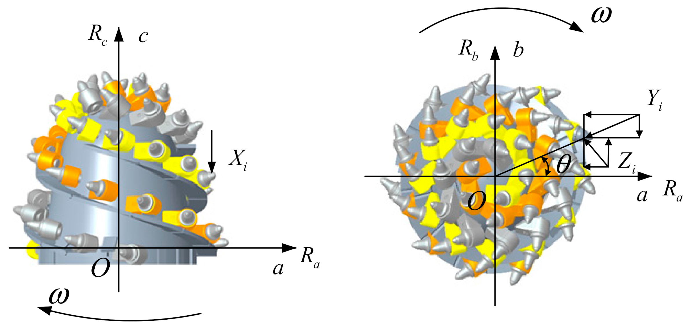
2.1. Random Load of Pick

When the cantilever roadheader cuts complex rock strata, the cutting resistance Zi, traction resistance Yi, and lateral resistance Xi [18] (shown in Figure 1) of the i-th pick on the cutting head are respectively
Z i   = Z n   = Z max n k C Z k b Z k Y Z k φ Z Y i   = Y n   = Y max n k b Y k Y K k φ Y X i   = X n   = Z n k X
where, Zmax[n] is the average peak value of cutting resistance of the standard pick, Ymax[n] is the average peak value of traction resistance, kCZ is the influence coefficient of pick arrangement, kbZ is the width coefficient of the cut section in the z-direction, kbY is the width coefficient of the cut section in the y-direction, kYZ is the influence coefficient of cutting angle, kφZ is the front edge shape coefficient in the z-direction, kφY is the front edge shape coefficient in the y-direction, kYK is the shape coefficient of cutting edge, and kX is the ratio of lateral resistance to cutting resistance [19,20,21].
The components in the rock stratum are complex, and the load fluctuates violently. The random load of the pick follows the χ2 distribution random process with two-degree freedom and the correlation coefficient R τ τ   = σ z e α τ . The process Zcp is obtained by the sum of two independent stationary random processes ξ1(t) and ξ2(t) with mathematical expectation μ = 0, standard deviation D = 1, and standard coherence function γ 0   = e α τ / 2 . Namely,
Z c p t   = ξ 1 t + ξ 2 t
The center value of the random process at the time of n⋅Δt is
Z c p n   = ξ 1 2 n + ξ 2 2 n 2 ,   n   = 1 , 2 , 3 , 4
where
ξ 1 n   = 1 ρ 1 2 n η 1 n + ρ 1 n ξ 1 n 1 ,   n   = 2 , 3 , 4
ξ 2 n   = 1 ρ 1 2 n η 2 n + ρ 1 n ξ 2 n 1 ,   n   = 2 , 3 , 4
η 1 n and η 2 n are two mutually independent normal random number sequences, ξ 1 1   = η 1 1 , ξ 2 1   = η 2 1 , ρ 1 n is a sequence of uniformly distributed random numbers on the interval (0,1).
Therefore, the random cutting resistance of the i-th pick at the time of n⋅Δt is
Z i   = Z n   = σ 0 Z c p + Z ¯ i   = σ Z 2 n + Z ¯ i
where Z ¯ i is the average cutting resistance of the i-th pick at the moment of n⋅Δt, σ0 is the coefficient of the central value of the cutting resistance of the pick in the complex rock stratum, and σZ is the standard deviation of the cutting resistance load of the pick obeying the χ2 distribution.
Due to the large correlation between cutting resistance and traction resistance, the random traction resistance of the i-th pick at time n⋅Δt can be determined by the correlation number RZY of Zcp and Ycp
Y i   = Y n   = σ Y σ 0 R Z Y Z c p n + 1 R Z Y 2 η 3 n + Y ¯ i
where Y ¯ i is the average traction resistance of the i-th pick at the time of n⋅Δt, σY is the standard deviation of the random process Y n , VY is the variation coefficient, and η 3 n is the normal random sequence with mathematical expectation Eη3 = 0 and standard deviation Dη3 = 1.
The random lateral resistance Xi is expressed as
X i   = Z i C 1 C 2 + h + C 3 h t
where C1, C2 and C3 are the influence coefficients of the chip diagram, h is the average chip thickness of the pick, and s is the average intercept spacing.

2.2. Random Load of Cutting Head
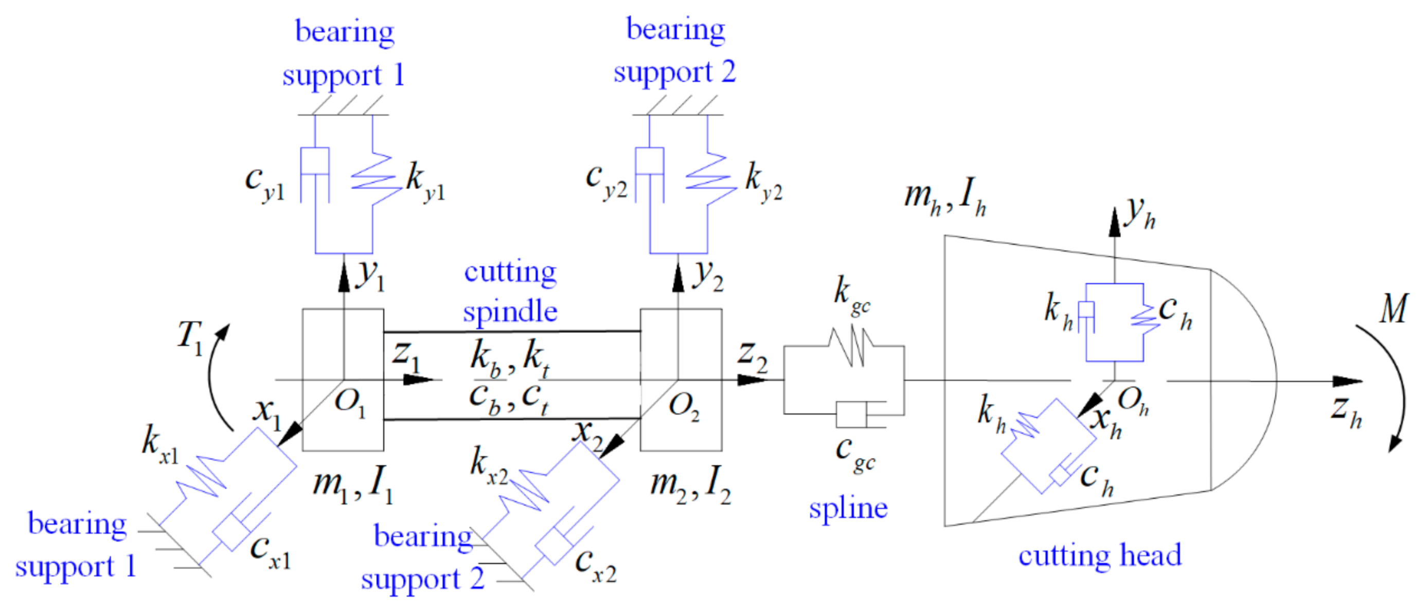
The working process of the roadheader is mainly divided into axial drilling, horizontal cutting, and vertical cutting. Under the three motion modes, the pick on the cutting head is subject to the random cutting resistance Zi, random traction resistance Yi and random lateral resistance Xi [22]. According to the force projection on each pick participating in the cutting along with the spatial coordinates (a, b, c) of the cutting head [23] (as shown in Figure 1), the instantaneous three-way random cutting load and a load torque of the cutting head can be derived thus
R a   = i   = 1 n j Z i sin θ i + Y i cos θ i
R b   = i   = 1 n j Y i sin θ i Z i cos θ i
R c   = i   = 1 n j X i
M   = i   = 1 n j Z i r g i
where nj is the total number of picks participating in cutting at the same time, θi is the circumferential angle of the i-th pick, and rgi is the tooth tip rotation radius of the i-th pick.

3. Dynamics Model

3.1. Bearing Vibration Model

Two groups of bearings are arranged on the cutting main shaft. The outer ring of the rolling bearing is fixed on the cantilever shell, and does not rotate. The inner ring is fixed on the main shaft, and rotates with the main shaft at an angular speed ω. vi is the linear velocity of the contact point between the bearing roller and the bearing inner ring, and v0 is the linear velocity of the contact point between the bearing roller and the bearing outer ring.
v i   = ω i r
v 0   = ω 0 R
where r and R are the rolling radius of the bearing’s inner and outer rings, respectively. If the angular velocity of the bearing cage is equal to the angular velocity of the bearing roller revolution, then ω0 = 0, ωi = ω. So, the angular velocity of the cage
ω d   = v i + v 0 / R + r   = ω i r / R + r
Then the rotation angle αi of the i-th bearing roller is
α i   = ω d t + 2 π i 1 / N b       i   = 1 , 2 , , N b
The vibration displacement of the rolling bearing center in two directions is xv and yv respectively; γ0 represents the bearing clearance, and then the contact deformation between the i-th bearing roller and the inner and outer race raceway can be expressed as
δ i   = x v cos α i + y v sin α i γ 0       i   = 1 , 2 , , N b
where Nb is the number of bearing rollers.
According to the nonlinear Hertz contact theory, Fi represents the contact pressure between the i-th bearing roller and the raceway in the case of rolling contact. The contact between the bearing roller and the raceway only produces normal positive pressure, and the nonlinear Hertz force is only valid when δi > 0.
F i   = k c δ i 3 / 2 H δ i   = k c x v cos α i + y v sin α i γ 0 3 / 2 H x v cos α i + y v sin α i γ 0
where kc is Hertz contact stiffness, H(x) is the Heaviside function. When the function variable is greater than 0, the function value is 1, otherwise, it is 0.
The nonlinear Hertz forces of bearing support force are
F   = i   = 1 N b k c x cos α i + y sin α i γ 0 3 / 2 · H x cos α i + y sin α i γ 0
F y j   =   F sin α i F x j   =   F cos α i     j   = 1 , 2 ; i   = 1 , 2 , N b
The support stiffness of the bearing in the x or y direction can be expressed as
k y   =   d F y j / d y k x   =   d F x j / d x     j   = 1 , 2

3.2. Dynamic Model of Cutting Head Rotor System
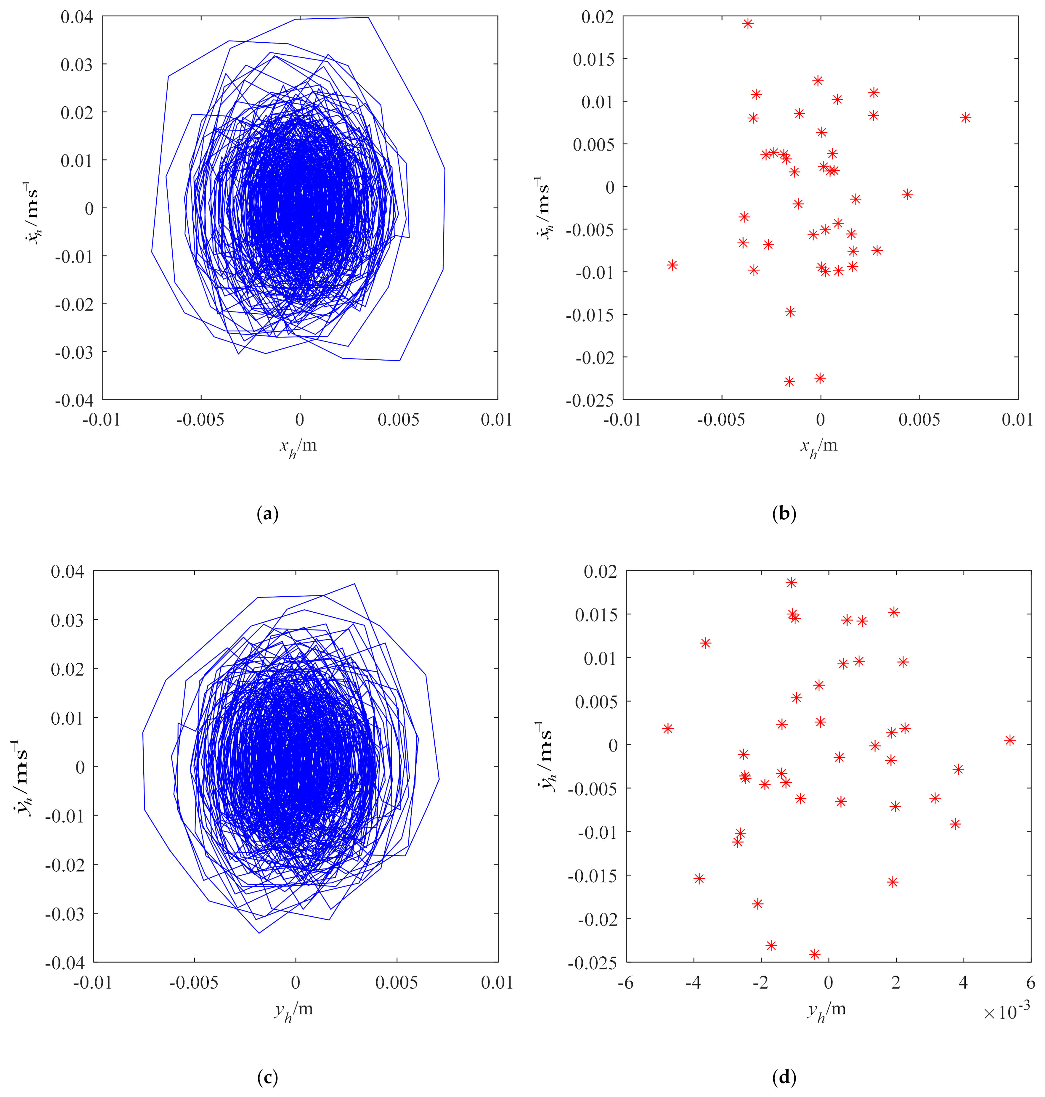
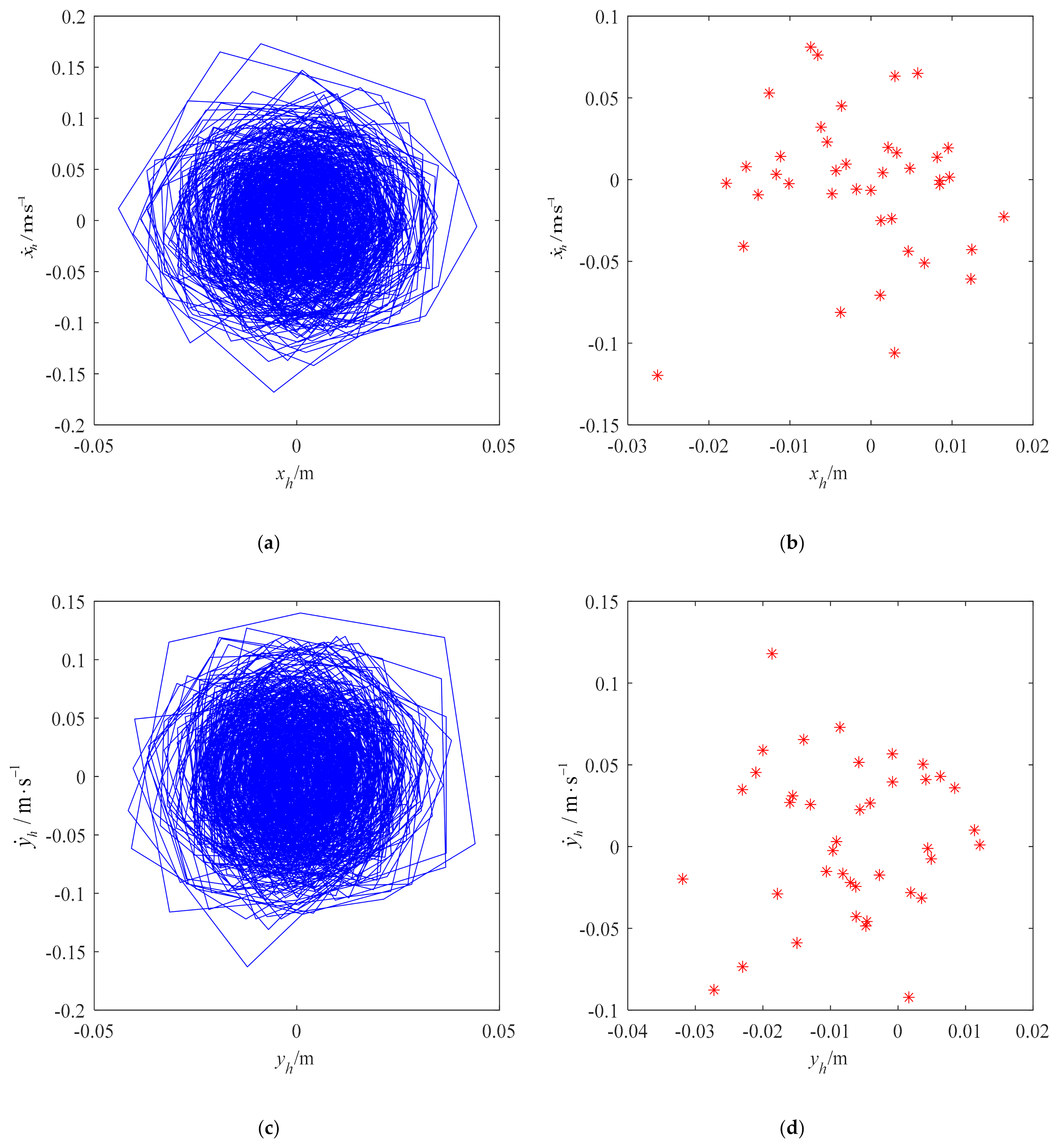
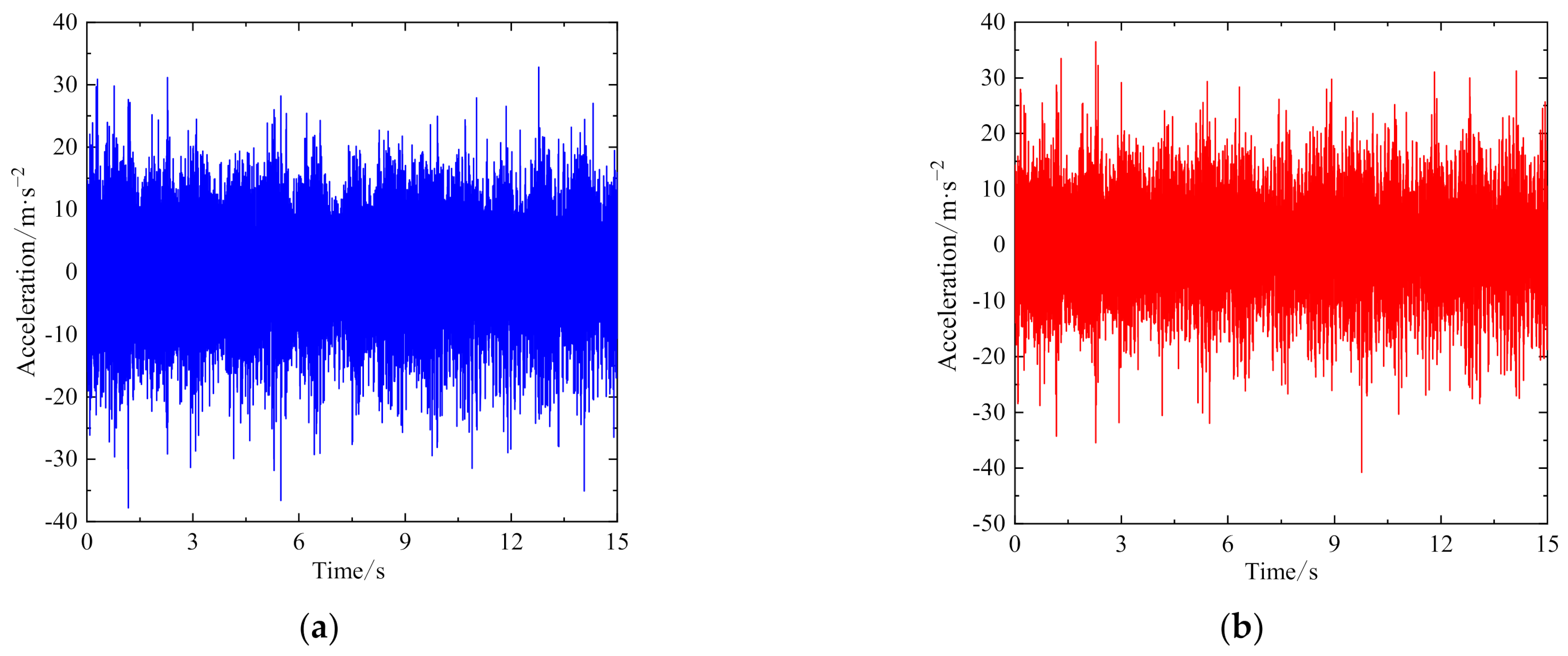
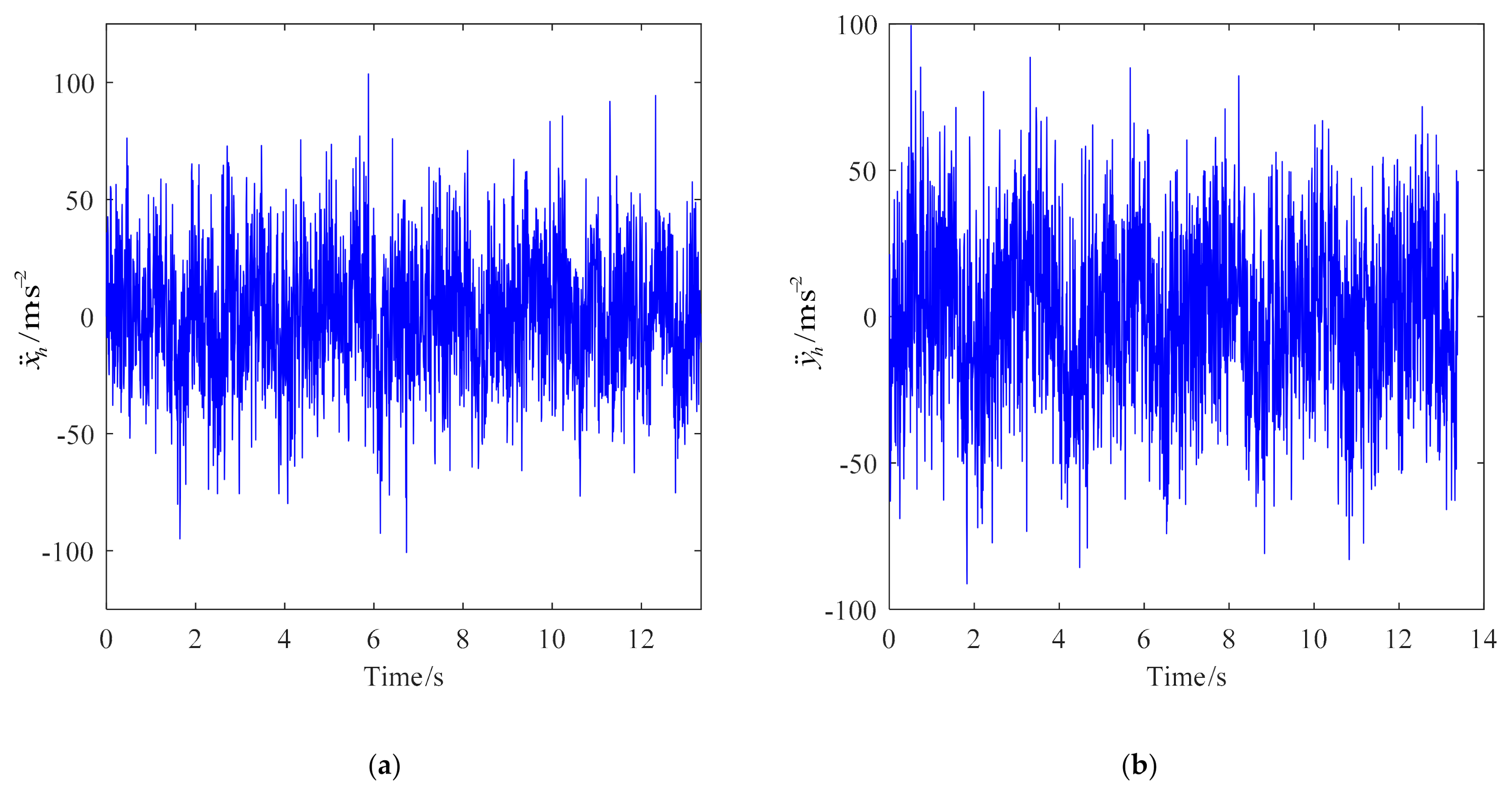
The cantilever transmission system of the roadheader provides stable rotating power for the cutting head to cut the rock stratum [24]. The simplified structure of the cutting head rotor system of the roadheader is shown in Figure 2. The cutting main shaft is supported by rolling bearings, and the cutting head is supported by a spline shaft and shell.
Considering the transverse and torsional vibration of the rotor system composed of cutting head, cutting spindle and bearing, the displacement vector of the system is
X   = x 1 , y 1 , φ 1 , x 2 , y 2 , φ 2 , x 3 , y 3 , φ 3 T
where xi, yi, φi (i = 1,2,…h) is the displacement in the x and y-axis and the rotation angle around the z-axis of mass point i. Applying Lagrange equation, according to the dynamic model in Figure 2, the dynamic differential equation of the cutting head rotor system is established as follows
m 1 x ˙ 1 + k x 1 x 1 + k b ( x 1 x 2 ) + c 1 x ˙ 1 + c b ( x ˙ 1 x ˙ 2 )   = 0
m 1 y ¨ 1 + k y 1 y 1 + k b ( y 1 y 2 ) + c 1 y ¨ 1 + c b ( y ¨ 1 y ¨ 2 )   = 0
I 1 φ ¨ 1 + k t ( φ 1 φ 2 ) + c t ( φ ˙ 1 φ ˙ 2 )   = T 1
m 2 x ¨ 2 + k x 2 x 2 k b ( x 1 x 2 ) + c 2 x ¨ 2 c b ( x ˙ 1 x ˙ 2 ) + k h ( x 2 x h ) + c h ( x ˙ 2 x ˙ h )   = 0
m 2 y ¨ 2 + k y 2 y 2 k b ( y 1 y 2 ) + c 2 y ˙ 2 c b ( y ˙ 1 y ˙ 2 ) + k h ( y 2 y h ) + c h ( y ˙ 2 y ˙ h )   = 0
I 2 φ ¨ 2 k t ( φ 1 φ 2 ) + k g c ( φ 2 φ h ) c t ( φ ˙ 1 φ ˙ 2 ) + c g c ( φ ˙ 2 φ ˙ h )   = 0
m h x ¨ h k h ( x 2 x h ) c h ( x ˙ 2 x ˙ h )   = R b
m h y ¨ h k h ( y 2 y h ) c h ( y ˙ 2 y ˙ h )   = R a
I h φ ¨ h k g c ( φ 2 φ h ) c g c ( φ ˙ 2 φ ˙ h )   = M
In order to accurately study the dynamic characteristics of the cutting mechanism and the rotor system of the cantilever roadheader on the basis of the original model with the torsional degrees of freedom of the cutting head and cutting arm, the new model also takes the transverse and longitudinal degrees of freedom into account. Therefore, the time-varying stiffness characteristic of the main shaft bearings in the cutting arm and the bending-torsion coupling characteristic of the main shaft can be reflected in the new model, so as to ensure the theoretical basis of the cutting mechanism rotor system dynamic analysis. The above equation presents a complex mathematical model [25,26]. It is a strong nonlinear system. After dimensionless, the Newmark- β Method is used for a numerical solution.

4. Results

This study takes the XTR06/260 roadheader as an example for calculation and analysis, and the parameter settings are shown in Table 1.
The rotation speed of the roadheader cutting head is inversely proportional to the output cutting force. To ensure that the cutting head has reasonable cutting force under different conditions, the dynamic response of the cutting head rotor system will be discussed. For the rock, the Protodyakonov coefficient fp is 6 and 10.
Based on the commercial software MATLAB, the horizontal cutting rock stratum of the roadheader is set to simulate the random load of the cutting head under the following two typical working conditions: (1) fp = 6, the cutting head rotate speed n = 55 r/min, the speed frequency fr = 0.92 Hz, the spline meshing frequency fm = 45.08 Hz, and the swing speed vb = 1.5 m/min; (2) fp = 10, the cutting head rotate speed n = 27 r/min, speed frequency fr = 0.45 Hz, spline meshing frequency fm = 22.05 Hz, and cutting head swing speed vb = 1 m/min.
For the cutting head rotor system, each component has the typical characteristics of nonlinear vibration accompanied by instantaneous impact. The vibration acceleration of the cutting head is greater than that of the cutting spindle. According to the vibration transmission path from the cutting head to the cutting spindle, the cutting head is close to the excitation source and the vibration acceleration is large. In addition, the rolling bearing rotation at the rear of the cutting head rotor system introduces a large number of high-frequency components, which also make the vibration acceleration less than that at the front. Since most of the working time of the roadheader is in the cross-cutting condition, the vibration characteristics of the cutting head under the cross-cutting condition are mainly analyzed below. In the characteristic frequency analysis, frequency components with large power spectrum amplitude were mainly selected because these frequency components have the greatest impact on the vibration of the cutting mechanism, and the influence of the same frequency components on the cutting mechanism vibration in the x and y directions was considered.
Figure 3 is the time-domain curve and spectrum of cutting head vibration acceleration in x and y directions when fp = 6. Under the excitation of rock breaking dynamic force, the time-domain curve of cutting head vibration acceleration shows irregular yet strong oscillation. The vibration frequency is mainly concentrated in low frequency, and the frequency is complex. The main characteristic frequencies in the x-direction are 1.95 Hz, 5.86 Hz, 9.12 Hz and 50.81 Hz respectively, while the main characteristic frequencies in the y-direction are 1.95 Hz, 3.91 Hz, 9.12 Hz and 25.4 Hz respectively, and their vibration frequencies are close to the frequency doubling of the rotation frequency of the main shaft. This frequency distribution feature is related to the distribution of the pick. There are 38 picks on the cutting head of the analysis model, most of which are arranged on multiple helixes. The top of the cutting head is more densely arranged than the bottom pick, which may produce a vibration frequency that is multiple times the conversion frequency.
Figure 4 is the time-domain curve and spectrum of cutting head vibration acceleration in x and y directions when fp = 10. Due to the hard rock and the strong impact characteristics of rock breaking force, the maximum vibration acceleration exceeds 100 m/s2 at a few time points. The vibration frequency is still concentrated in the low frequency, the main frequencies in the x-direction are 0.97 Hz, 1.93 Hz, 2.9 Hz, 9.35 Hz and 22.53 Hz respectively, the main frequencies in the y-direction are 0.97 Hz, 1.93 Hz, 2.58 Hz, 11.92 Hz and 24.17 Hz respectively, and their vibration frequencies are close to the frequency doubling of the spindle rotation frequency.
Figure 5 and Figure 6 are the vibration phase diagram and Poincaré section of the cutting head under two kinds of hardness respectively. It can be seen from the figures that the phase diagram trajectories of the cutting head rotor system are composed of a large number of approximate ellipses, and the phase diagram trajectories intersect, but the phase diagram trajectory curves are not smooth due to severe vibration, discontinuous speed, and displacement. There are many scattered points in the Poincaré section, which indicates that there is chaotic behavior in the vibration of the cutting head rotor system.

5. Experiments

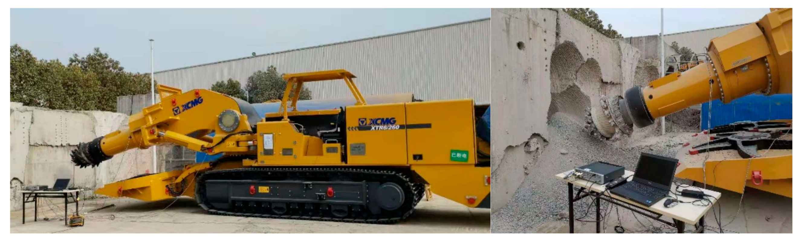
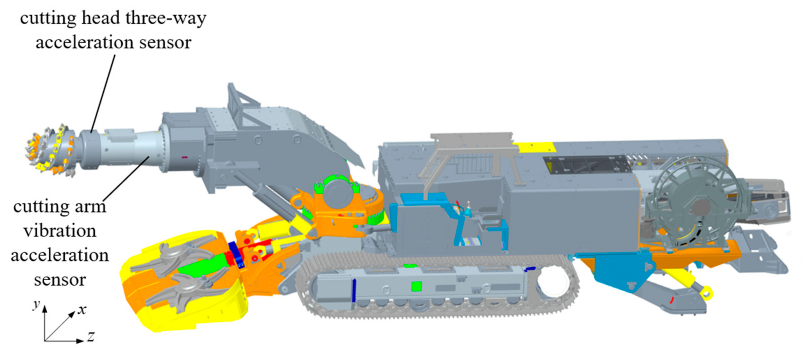
5.1. Experimental Setup

The experimental object XTR260 roadheader has a mass of 90 t and cutting power of 200~260 kW. The loading is realized by cutting the artificial concrete wall with protodyakonov coefficient fp = 6. The speed of the cutting head is set to 55 r/min, the swing speed of the cutting head is 1.5 m/s, and the size of the artificial concrete wall is 6 m × 2.8 m × 1.2 m. The experimental site is shown in Figure 7.

5.2. Test Devices

The vibration signal of the roadheader during operation is collected through sensors, which include DONGHUA 1A313E three-way sensors and LZDL1-Y vibration sensors. The test system consists of sensors, Siemens LMS SCADAS data acquisition system, and the LMS test lab software. The sensors’ arrangement is shown in Figure 8. Since it is difficult to install the sensors stably on the cutting head, the sensors for measuring the cutting head are installed on the cantilever shell close to the cutting head without rotation.

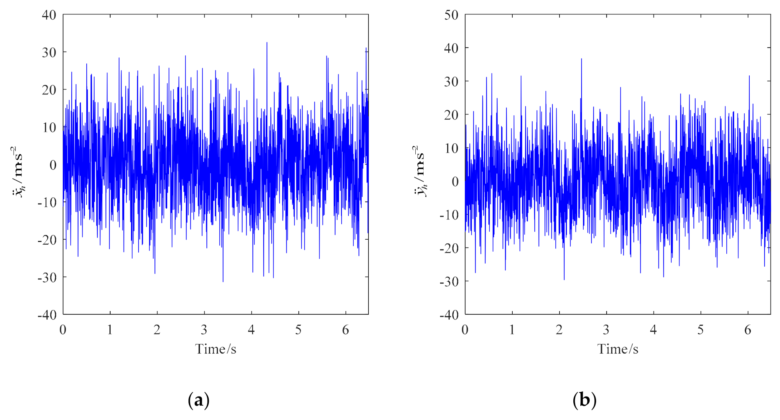
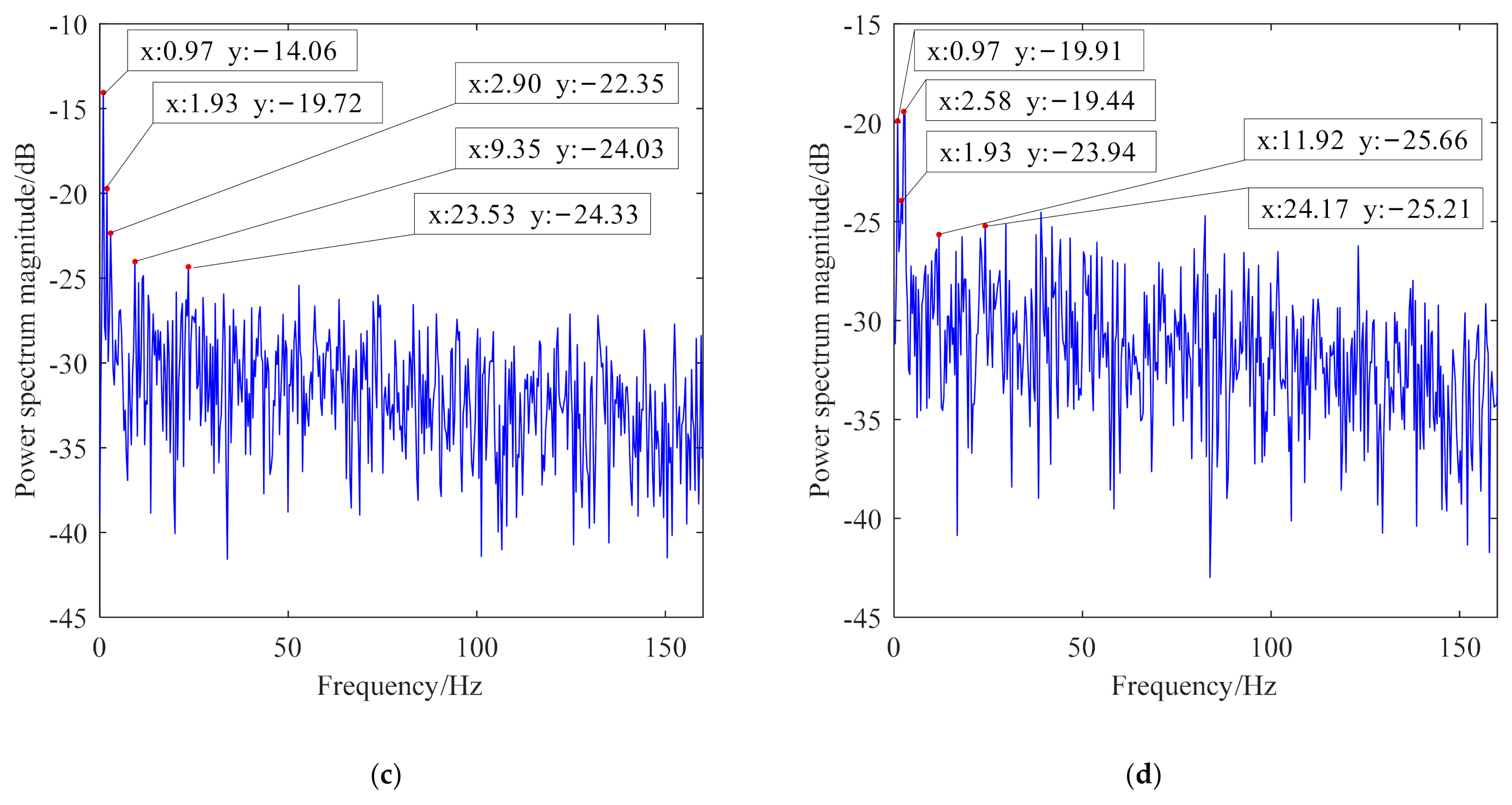
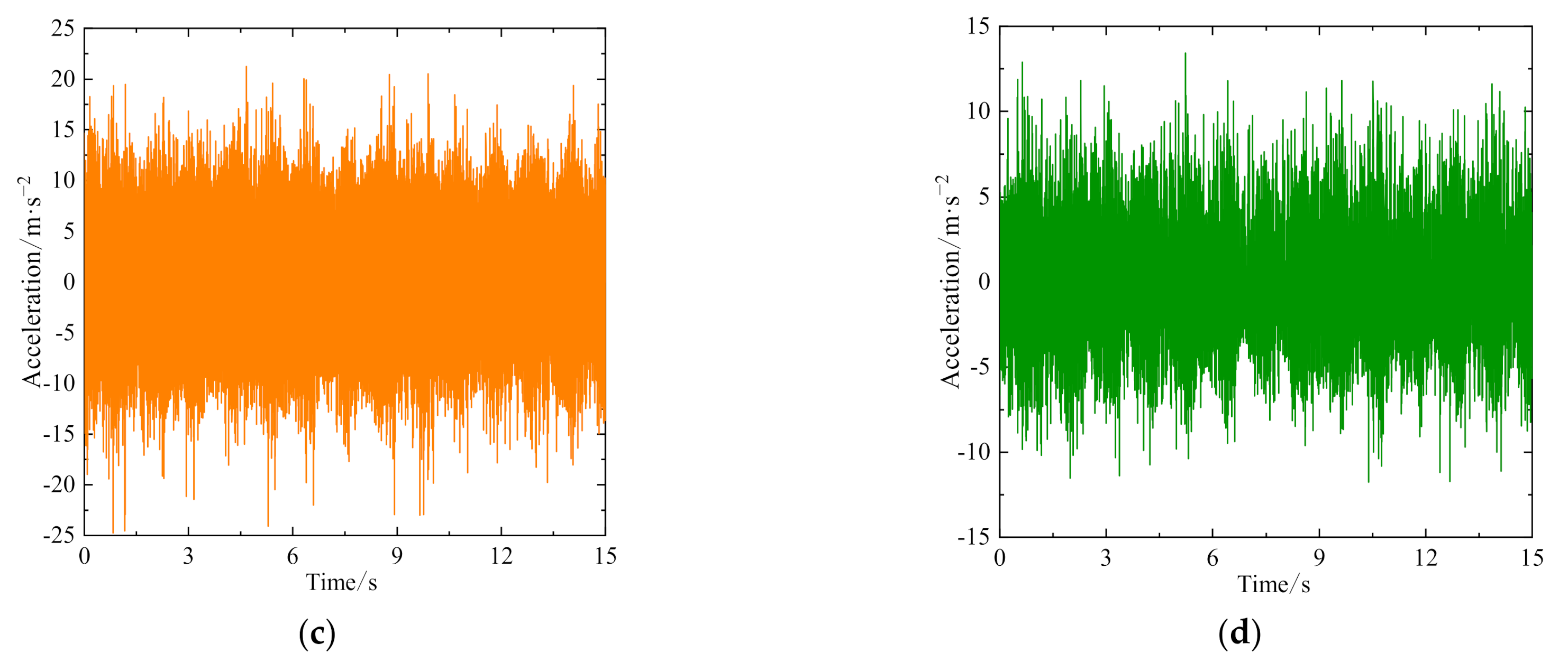
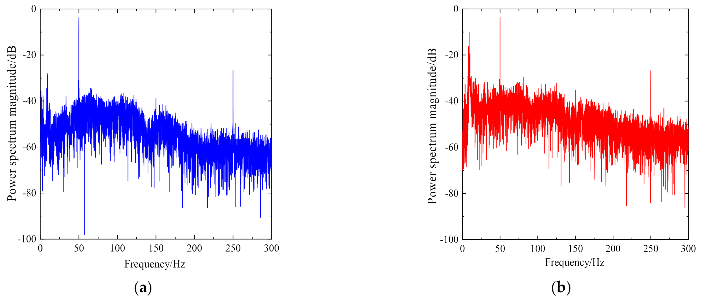
5.3. Experimental Results

As the cutting mechanism of the roadheader adopts a two-stage planetary gear reducer, many gears mesh with each other. The time-varying meshing stiffness, tooth side clearance, meshing impact, and design and manufacturing error of the gears cause internal excitation and vibration of the cutting head. Under the no-load condition, the vibration fluctuation is relatively small, and the vibration of each component is stable, which is a quasi-periodic form. Due to the long cantilever of the cutting mechanism, the three-dimensional vibration amplitude of the cutting head is the largest, as shown in Table 2.
It can be seen from Table 2 that the effective value of three-dimensional vibration of the cutting head under no-load condition is close. Under the cross-cutting condition, the vibration in y direction is the largest, followed by x direction, and the vibration in z direction is the smallest. According to the cutting theory of the roadheader, the three-dimensional force on the cutting head has great correlation. It can be seen from Table 3 that the vibration frequency composition of the cutting head in three directions are basically the same, which is in line with the actual situation of the cutting mechanism.
Under the cutting condition, with the excitation of the rock breaking dynamic random load, the time-domain curve of cutting head vibration acceleration shows irregular strong oscillation, as shown in Figure 9. The vibration frequency is mainly concentrated in low frequency, and the frequency is complex, as shown in Figure 10. Its characteristic frequency points are shown in Table 3. The main characteristic frequencies in x and y directions are the same, which are 1.9 Hz, 3.4 Hz, 9 Hz and 50 Hz respectively. Their vibration frequencies are close to the frequency doubling and mixing of the main shaft frequency. Among them, 50 Hz is the mixing of fm + 5 fr, with a large amplitude, and its vibration of 5 times the frequency of 250 Hz is also prominent. This is because the sensors are installed near the spline of the cutting head, and cutting the main shaft results in a large mixing vibration amplitude of spline meshing frequency and frequency conversion. This frequency component is also prominent in the no-load test. The measuring point of the cutting arm is far away from the cutting head of the excitation source, and not at the spline location between the cutting head and the main shaft. In addition, the randomness of load and human operation makes the power spectrum amplitude at 50 Hz suddenly decrease as compared with the three-dimensional power spectrum amplitude of the cutting head.

6. Conclusions

It can be seen from the measured and simulated curves that the dynamic acceleration curve obtained by the multi-degree-of-freedom dynamic equation of the cutting head rotor system under the condition of random load force is in line with the change law of the measured curve, and fluctuates around a close mean value. The frequency characteristics of the simulated curve and the measured curve are also relatively close, which verifies that the established dynamic model conforms to the actual situation. The simulated random load can replace the measured load.
In this study, the dynamic mechanical response of the cutting head rotor system under different kinds of rock hardness has been analyzed. The cutting head rotor system displays chaotic motion under random load, with complex frequency components and obvious frequency amplitude fluctuations. The characteristic frequency is mainly the frequency conversion and frequency doubling of the spindle. In the design and development of a cantilever tunnel roadheader for hard rock, the vibration characteristics and rigid–flexible coupling vibration of different substructures of the system should be considered when modeling the dynamic theory of the cutting mechanism, to improve the reliability and safety of the roadheader during its service. The dynamic analysis method of the cutting head rotor system provides a theoretical basis for vibration reduction and dynamic design of the roadheader.
The dynamic model refinement also provides a new theoretical basis for the dynamic design and accurate measurement [27,28] of other cutting construction machinery, such as coalcutters. This also amounts to important basic work in the cooperative operation of heavy engineering equipment [29] and innovation of intelligent construction technology [5].

Author Contributions

Conceptualization, S.C. and Y.L.; methodology, Z.Z.; software, H.W.; validation, C.C.; formal analysis, Y.L.; investigation, Y.L. and Z.Z.; data curation, H.W.; writing—original draft preparation, H.W.; writing—review and editing, Y.L.; project administration, Z.Z.; funding acquisition, Z.Z. All authors have read and agreed to the published version of the manuscript.

Funding

This research was funded by the Priority Academic Program Development of Jiangsu Higher Education Institutions [PAPD], the Primary Research & Development Plan of Jiangsu Province [BE2015039].

Data Availability Statement

The data presented in this study are available on request from the corresponding author.

Acknowledgments

The authors would like to express sincere appreciation to the editor and the anonymous reviewers for their valuable comments and suggestions for improving the presentation of the manuscript.

Conflicts of Interest

The authors declare no conflict of interest.

References

  1. Seker, S.E.; Ocak, I. Performance prediction of roadheaders using ensemble machine learning techniques. Neural Comput. Appl. 2019, 31, 1103–1116. [Google Scholar] [CrossRef]
  2. Zhao, X.; Rao, J.; Cheng, C.; Xie, C. Application of cantilever roadheader in tunnel construction. In IOP Conference Series: Earth and Environmental Science; IOP Publishing: Bristol, UK, 2019; Volume 330, p. 022023. [Google Scholar] [CrossRef]
  3. Cheluszka, P. Optimization of the cutting process parameters to ensure high efficiency of drilling tunnels and use the technical potential of the boom-type roadheader. Energies 2020, 13, 6597. [Google Scholar] [CrossRef]
  4. Zhang, M.; Lyu, F.; Tang, X.; Yang, Y.; Ji, X.; Wu, M. Analysis of vibration of roadheader rotary table based on finite element method and data from underground coalmine. Shock Vib. 2018, 2018, 4396520. [Google Scholar] [CrossRef] [Green Version]
  5. Zhang, M.; Lyu, F.; Li, C.; Li, X.; Wu, M. The roadheader auto-rectification dynamic analysis and control based on the roadway floor mechanic characteristics. Arab. J. Sci. Eng. 2021, 46, 2649–2661. [Google Scholar] [CrossRef]
  6. Deshmukh, S.; Raina, A.K.; Murthy, V.M.S.R.; Trivedi, R.; Vajre, R. Roadheader—A comprehensive review. Tunn. Undergr. Space Technol. 2020, 95, 103148. [Google Scholar] [CrossRef]
  7. Li, S.; Zhang, P.; Xi, C. Impulse processing algorithm for random source signals of roadheaders that is based on compound interferometry. J. Environ. Eng. Geophys. 2021, 26, 13–24. [Google Scholar] [CrossRef]
  8. Yang, Y.; Li, G.; Yuan, A. Performance analysis of a hybrid power cutting system for roadheader. Math. Probl. Eng. 2017, 2017, 1359592. [Google Scholar] [CrossRef]
  9. Zhang, D.; Liu, S.; Jia, X.; Cui, Y.; Yao, J. Full coverage cutting path planning of robotized roadheader to improve cutting stability of the coal lane cross-section containing gangue. Proc. Inst. Mech. Eng. Part C J. Mech. Eng. Sci. 2022, 236, 579–592. [Google Scholar] [CrossRef]
  10. Wang, H.; Sun, D.; Qin, D. A new continuously variable transmission system applied to transmission system of the roadheader’s cutting unit. Proc. Inst. Mech. Eng. Part C J. Mech. Eng. Sci. 2017, 231, 3590–3600. [Google Scholar] [CrossRef]
  11. Li, Z.; Sun, D.; Qin, Y.; Zhang, W.; Sun, B. Stiffness-damping matching modelling for vibration isolation system of roadheader ECB. Int. J. Acoust. Vib. 2020, 25, 54–61. [Google Scholar] [CrossRef]
  12. Shen, Y.; Wang, P.; Zheng, W.; Ji, X.; Jiang, H.; Wu, M. Error compensation of strapdown inertial navigation system for the boom-type roadheader under complex vibration. Axioms 2021, 10, 224. [Google Scholar] [CrossRef]
  13. Li, X.; Gu, Y.Z.; Wu, M. Kinematics analysis of roadheader’s working mechanism based on differential geometry. J. China Coal Soc. 2016, 41, 3158–3166. [Google Scholar]
  14. Wei, X.H. Dynamic Characteristic Analysis and Performance Prediction of Cutting Process for Boom-Type Roadheader. Ph.D. Thesis, School of Mechatronic Engineering, Liaoning Technical University, Fuxin, China, 2013. [Google Scholar]
  15. Zhao, L.J.; Tian, Z.; Sun, Y.; Zhou, Z.H. Vibration characteristics of a longitudinal roadheader. J. Vib. Shock. 2013, 32, 17–20. [Google Scholar] [CrossRef]
  16. Li, X.H.; He, Y.; Li, T.; Yang, T.T. Analysis of horizontal and vertical random vibration responses of longitudinal roadheader. J. China Coal Soc. 2014, 39, 580–585. [Google Scholar] [CrossRef]
  17. Huang, Z.; Zhang, Z.; Li, Y.; Song, G.; He, Y. Nonlinear dynamic analysis of cutting head-rotor-bearing system of the roadheader. J. Mech. Sci. Technol. 2019, 33, 1033–1043. [Google Scholar] [CrossRef]
  18. Zhang, M.; Yan, X.; Qin, G. A new method for roadheader pick arrangement based on meshing pick spatial position and rock cutting verification. PLoS ONE 2021, 16, e0260183. [Google Scholar] [CrossRef]
  19. He, Y.; Tian, M.; Song, J.; Feng, J. Rock hardness identification based on optimized PNN and multi-source data fusion. Proc. Inst. Mech. Eng. Part C J. Mech. Eng. Sci. 2021, 09544062211042048. [Google Scholar] [CrossRef]
  20. Jiang, H.; Liu, S.; Changlong, D.; Gao, K. Numerical simulation of rock fragmentation process by roadheader pick. J. Vibroeng. 2013, 15, 1807–1817. [Google Scholar]
  21. Kang, H.; Cho, J.; Park, J.; Jang, J.; Kim, J.; Kim, K.; Rostami, J.; Lee, J. A new linear cutting machine for assessing the rock-cutting performance of a pick cutter. Int. J. Rock Mech. Min. Sci. 2016, 88, 129–136. [Google Scholar] [CrossRef]
  22. Li, X.; Huang, B.; Ma, G.; Zeng, Q. Study on roadheader cutting load at different properties of coal and rock. Sci. World J. 2013, 2013, 624512. [Google Scholar] [CrossRef] [Green Version]
  23. Cheluszka, P. Numerical studies of the dynamics of the roadheader equipped with an automatic control system during cutting of rocks with different mechanical properties. Energies 2021, 14, 7353. [Google Scholar] [CrossRef]
  24. Zong, K.; Fu, S.; Li, X.; Wu, M.; Chu, F. Modelling and response analysis of multibody large-scale displacement of boom-type roadheader. J. Multi-Body Dyn. 2021, 235, 326–337. [Google Scholar] [CrossRef]
  25. Yasar, S.; Yilmaz, A.O. A novel mobile testing equipment for rock cuttability assessment: Vertical rock cutting rig (VRCR). Rock Mech. Rock Eng. 2017, 50, 857–869. [Google Scholar] [CrossRef]
  26. Ji, X.; Zhang, M.; Qu, Y.; Jiang, H.; Wu, M. Travel dynamics analysis and intelligent path rectification planning of a roadheader on a roadway. Energies 2021, 14, 7201. [Google Scholar] [CrossRef]
  27. Cheluszka, P.; Jagiela-Zajac, A. Validation of a Method for Measuring the Position of Pick Holders on a Robotically Assisted Mining Machine’s Working Unit. Energies 2022, 15, 295. [Google Scholar] [CrossRef]
  28. Bartoszek, S.; Cwikla, G.; Kost, G.; Niespialowski, K. Impact of the Selected Disturbing Factors on Accuracy of the Distance Measurement with the Use of Ultrasonic Transducers in a Hard Coal Mine. Energies 2022, 15, 133. [Google Scholar] [CrossRef]
  29. Chen, H.; Yang, W.; Ma, Y.; Tian, L. Multi-sensor fusion method for roadheader pose detection. Mechatronics 2021, 80, 102669. [Google Scholar] [CrossRef]
Figure 1. Force distribution of the pick and cutting head. Zi is the cutting resistance of the i-th pick; Yi is the traction resistance of the i-th pick; Xi is the lateral resistance of the i-th pick; Ra is the cutting lift force of cutting head; Rb is the transverse resistance of cutting head; Rc is the propulsion resistance of cutting head.
Actuators 11 00083 g001
Figure 2. Structure diagram of the cutting head rotor system. The system includes the cutting spindle, bearing supports, connecting spline and cutting head. O1 and O2 are the origin of the coordinate system of the two concentrated masses m1 and m2 of the cutting spindle; Oh is the origin of the coordinate system of the concentrated mass mh of the cutting head. Ti is the input torque, M is the load torque of cutting head, kxi and kyi (I = 1, 2) are the bearing support stiffness in two directions, ci (I = 1, 2) is the bearing support damping, kb is the bending stiffness of cutting spindle, cb is the bending damping of cutting spindle, kt is the torsional stiffness of cutting spindle, ct is torsional damping of cutting spindle, kgc is the torsional stiffness of the spline between the cutting spindle and the cutting head, cgc is the torsional damping of the spline between the cutting spindle and the cutting head, kh is the bending stiffness of the cutting head, ch is the bending damping of the cutting head.
Actuators 11 00083 g002
Figure 3. Acceleration characteristics of the cutting head when fp = 6. (a) time-domain characteristics of acceleration in the xh-direction, (b) time-domain characteristics of acceleration in the yh-direction, (c) power spectrum of acceleration in the xh-direction, (d) power spectrum of acceleration in the yh-direction.
Actuators 11 00083 g003aActuators 11 00083 g003b
Figure 4. Acceleration characteristics of cutting head when fp = 10. (a) time-domain characteristics of acceleration in the xh-direction, (b) time-domain characteristics of acceleration in the yh-direction, (c) power spectrum of acceleration in the xh-direction, (d) power spectrum of acceleration in the yh-direction.
Actuators 11 00083 g004aActuators 11 00083 g004b
Figure 5. Vibration characteristics of the cutting head when fp = 6. (a) xh-direction vibration phase diagram of the cutting head, (b) xh-direction Poincaré section of the cutting head, (c) yh-direction vibration phase diagram of the cutting head, (d) yh-direction Poincaré section of the cutting head. Every “*” in (b,d) represents one cycle of vibration motion.
Actuators 11 00083 g005
Figure 6. Vibration characteristics of the cutting head when fp = 10. (a) xh-direction vibration phase diagram of the cutting head, (b) xh-direction Poincaré section of the cutting head, (c) yh-direction vibration phase diagram of the cutting head, (d) yh-direction Poincaré section of the cutting head. Every “*” in (b,d) represents one cycle of vibration motion.
Actuators 11 00083 g006
Figure 7. Experimental environment of tunneling operation.
Actuators 11 00083 g007
Figure 8. Measuring point and sensor arrangement of the roadheader. x. y, and z are the directions of the coordinate system established in the tunnel.
Actuators 11 00083 g008
Figure 9. Time-domain characteristics of the acceleration measured in the horizontal cutting experiment. (a) x-direction of the cutting head, (b) y-direction of the cutting head, (c) z-direction of the cutting head, (d) y-direction of the cutting arm.
Actuators 11 00083 g009aActuators 11 00083 g009b
Figure 10. Power spectrum of the acceleration measured in the horizontal cutting experiment. (a) x-direction of the cutting head, (b) y-direction of the cutting head, (c) z-direction of the cutting head, (d) y-direction of the cutting arm.
Actuators 11 00083 g010aActuators 11 00083 g010b
Table 1. Parameters of the cutting mechanism rotor system of XTR06/260.
ParametersValue
Spline teeth number of cutting spindle z 49
Spline modulus m (mm)5
Spline meshing stiffness kgc (N·m·rad−1)3.52 × 10⁸
Spline meshing damping ratio ξgc0.1
Cutting spindle weight m1, m2 (kg)350, 469
Moment of cutting spindle inertia I1, I2 (kg·m2)3.19, 4.06
Bending stiffness of cutting spindle kb (N·m−1)6.14 × 10⁸
Torsional stiffness of cutting spindle kt (N·m·rad−1)2.39 × 10⁷
Damping ratio of cutting spindle0.03
Picks number of cutting head38(Number of helices is 2)
Weight of cutting head mh (kg)1307
Moment of cutting head inertia Ih (kg·m2)93.53
Torsional stiffness of cutting head (N·m·rad−1)1.24 × 10⁸
Contact stiffness of rolling bearings kc1, kc2 (N·m−1)6.52 × 10⁸, 8.34 × 10⁸
Rolling bearing clearances γ01, γ02 (m)3 × 10⁻⁵, 2 × 10⁻⁵
Damping ratio of rolling bearing ξc0.02
Number of bearing rollers Nb1, Nb2 24, 31
Table 2. The peak vibration acceleration data in the time domain measured in the experiment.
Measuring PointDirectionNo-Load ConditionHorizontal Cutting Condition
Maximum Value (m·s−2)Variance
(m2·s−4)
Valid Value (m·s−2)Maximum Value (m·s−2)Variance
(m2·s−4)
Valid Value (m·s−2)
cutting headx11.724.34.9332.944.56.67
y11.925.05.0036.646.86.84
z10.423.44.8321.128.85.37
cutting army3.30.30.5113.57.52.74
Table 3. Acceleration power spectrum eigenfrequencies of the cutting head in the horizontal cutting experiment.
No.Measuring PointEigenfrequency Point
(a)x-direction of the cutting head(0.8, −36.8), (1.9, −38.4), (3.4, −32.5), (8, −36.4),
(9, −28), (50, −3.5), (250, −26)
(b)y-direction of the cutting head(0.8, −31.7), (1.9, −34.1), (3.4, −37.4), (8, −23.2),
(9, −18), (50, −2.9), (250, −30)
(c)z-direction of the cutting head(0.8, −42.3), (3.1, −37.4), (3.4, −32.5), (8, −16.7),
(9, −10), (50, −3.7), (250, −27)
(d)y-direction of the cutting arm(1.3, −36.1), (1.9, −34.5), (3.4, −44.7), (7, −27.9),
(9, −27.4), (50, −32), (230, −43.5)
Publisher’s Note: MDPI stays neutral with regard to jurisdictional claims in published maps and institutional affiliations.

