Abstract
The better application of crawl robots depends on their ability to adapt to unstructured environments with significant variations in their structural shape and size. This paper presents the design and analysis of a novel robot with different locomotion configurations to move through varying environments. The leg of the robot, inspired by insects, was designed as a multi-link structure, including the Hoekens linkage and multiple parallel four-link mechanisms. The end trajectory was a symmetrical closed curve composed of an approximate straight line and a shell curve with a downward opening. The special trajectory allowed the robot to share drives and components to achieve structural deformation and locomotion. The structural characteristics of the crawl robot on the inner and outer arcs were obtained based on the working space. The constraint relationship between the structure size, the radius of the arc, and the coefficient of static friction with which the robot could crawl on the arc were established. The feasible support posture and support position of the robot under different arc radii were obtained. The simulation tested the locomotion of the robot on the plane, arc, and restricted space. The robot can be used for detection, search, and rescue missions in unstructured environments.
1. Introduction
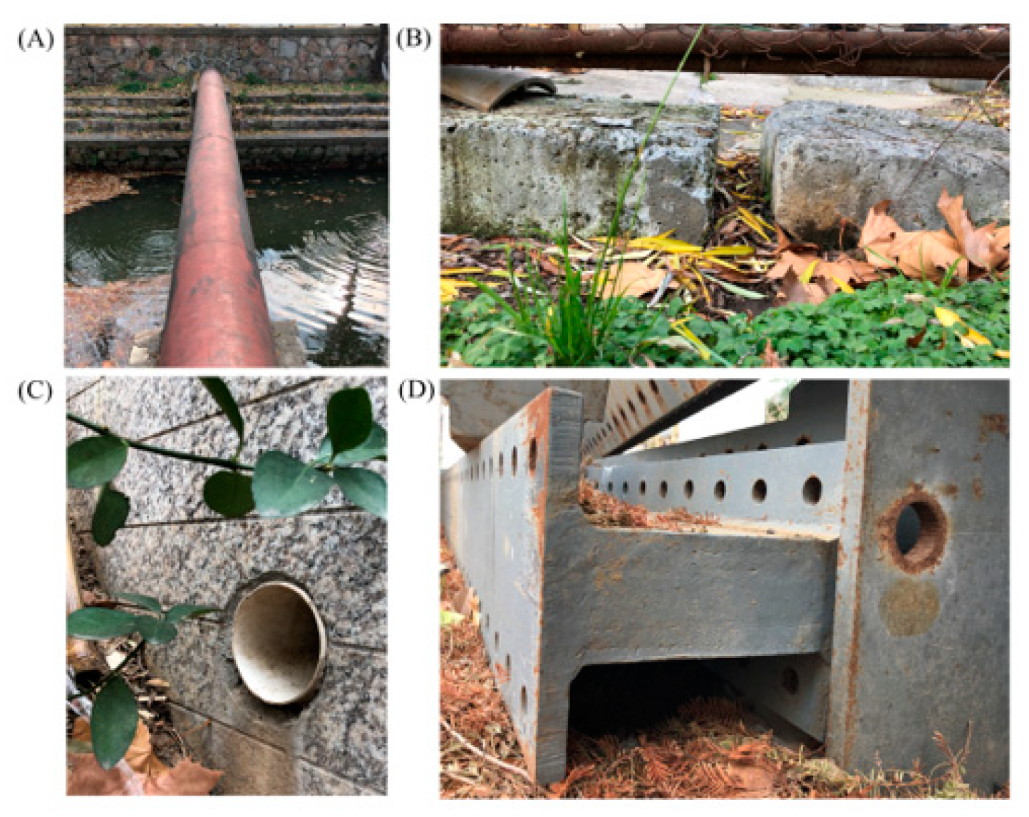
With the development of robotics, better applications in practical scenarios have become an important research topic. Robots need to interact with the physical environment to perform missions; in particular, the locomotion of crawl robots depends on the reaction force of the contact surface. Operation in unstructured environments, as shown in Figure 1, poses significant challenges to both the sentience and locomotion of robots. Unstructured environments include uneven terrains, narrow spaces, and inevitable obstacles.

Figure 1.
Typical unstructured environments. (A) Outer surface of pipe; (B) environment with restricted width; (C) inner surface of pipe; (D) environment with restricted height.
Animals have multiple strategies for adapting to unstructured environments. Animals have excellent perception; for instance, P. americana can combine their long antennae with their vision to examine and avoid barriers [1]. The long whiskers of rats and cats can detect the width of a doorway. In addition, animals have multiple locomotion modes. Lizards have multiple ways to overcome obstacles, such as jumping, crawling, and bipedal modes [2,3]. Locusts can switch between crawling and flying to increase agility, improve their performance, and reach places to which they cannot crawl [4]. The characteristics of an animal’s body structure also play an important role. The hard and streamlined shells of cockroaches enhance traversability through densely cluttered terrain [5], and can help them transition up a vertical wall after colliding with an obstacle [6]. Jayaram discovered that cockroaches can traverse horizontal crevices smaller than a quarter of their height, which has been an inspiration behind the development of the soft-legged hexapod robot named “compressible robot with articulated mechanisms” [7].
The study of the various characteristics of animals inspired the design of the robot. In addition to perfecting perception systems such as vision and tactile sensors [8,9], there are two methods for robots to overcome the challenges of unstructured environments in terms of mechanism design.
On one hand, robots can combine multiple locomotion strategies. Lussier developed an amphibious robot that combines crawling and flying, which can crawl, take off, and land on smooth/rough surfaces [10,11]. Robots that combine crawling and jumping modes can expand traversability in unstructured environments [12], and there are robots that mimic the locomotion strategies of vampire bats (MultiMo-Bat) and locusts (Jump-flapper), with capabilities of jumping and flying [13,14]. In the bimodal robot “LEONARDO”, the combination of bipedal movement and flight movement not only improves the robot’s movement ability, but also results in flexible and stable motion [15].
On the other hand, robots can improve the ability to transform structures and adapt to unstructured environments of different sizes and shapes. Chen proposed a wheel-legged robot that could switch modes through a switching mechanism, and the robot could pass through irregular terrain and cross obstacles [16]. Shang developed a deployable robot that can move in a space with limited height and width through structural deformations, such as unfolding and folding [17]. Ding presented a parallel robot that possesses large deformation capabilities (adapted to different pipe sizes), and foldable and expandable capabilities (folding into flat or prism shapes) [18].
At present, research on robots in terms of materials, drive, control, etc., is not comparable to that of animals. Designing multimodal robots with structural deformation capabilities or multiple motion modes is an important solution. However, many multi-modal robots simply superimpose various motion modes or they simply increase the drive to achieve structural transformation. The robot’s system is not only complex, and robustness is reduced, but it is even detrimental to the comprehensive motion performance of the robot. To address the gaps in this study, reasonable reduction and shared drives are required to accomplish motion and structural deformation.
In the present study, we aimed to develop a transformable crawl robot. Using the multi-link structure of the legs, shared drive, and structural components, the robot with special end-motion trajectories had a variety of configurations to cope with unstructured environments. This study could not only help to improve the crawling ability of the robot, but also provide a foundation for the research of multimodal robots that combine flying and jumping modes.
2. Design and Analysis of Robot Mechanism
2.1. Mechanism Design
A model diagram of the robot structure is shown in Figure 2, and the functional structure of the legs is inspired by insects.
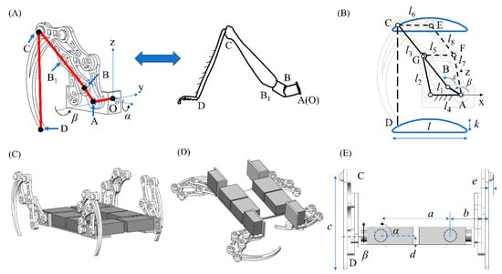
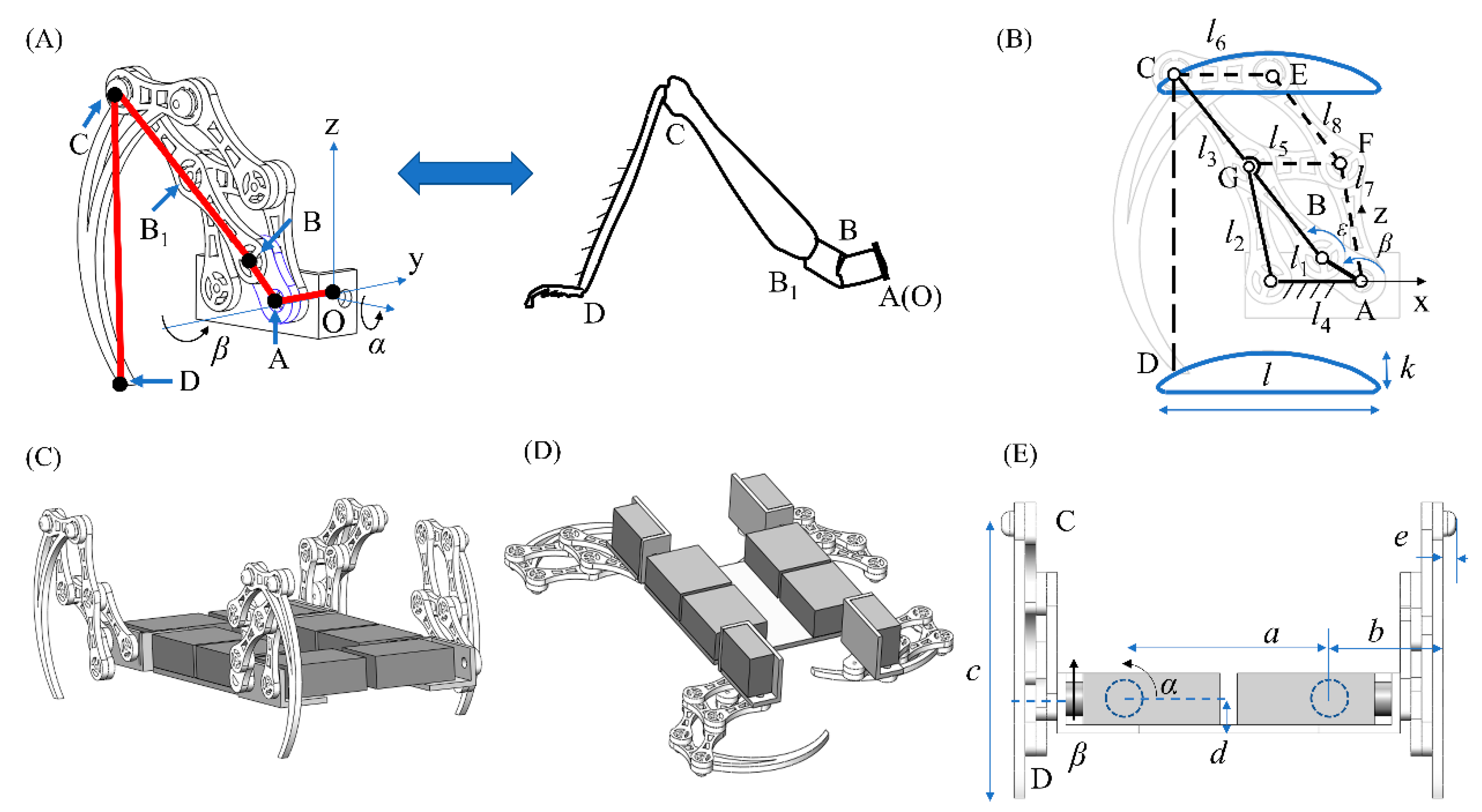
Figure 2.
Model diagram of the robot structure. (A) Multi-link leg structure inspired by insects; (B) kinematics parameters of the leg; (C) climbing robot with effective contact by point D (tarsus); (D) climbing robot with effective contact by point C (tibia); (E) the front view of the robot and main structure size parameters.
Figure 2A shows the multi-link leg structure of the robot. Insect legs are composed of the coxa (A/O–B), trochanter (B–B1), femur (B1–C), tibia (C–D), and tarsus (D–E). The connection between the base coxa and the body is equivalent to a ball hinge; the connection between the trochanter and the coxa is equivalent to a rotating hinge. The femur and trochanter are regarded as rods. The two connections between the femur and tibia, and the tibia and tarsus, are equivalent to rotating hinges.
For the robot structure design, the ball hinge between the coxa and the trochanter was simplified into two mutually perpendicular active rotating hinges, and the rotation angles are α and β, respectively. In the future, when we add adhesive pads or hooks to build a complete tarsus, we will install the rotating hinge of the tibia and tarsus. The core of the leg structure was the Hoekens link, and two parallel four-bar linkage structures were used to limit the end trajectory. The leg had two degrees of freedom: the shoulder joint (α) and the leg joint (β).
The robot had two locomotion configurations. The first configuration is shown in Figure 2C, which is supported by the tarsus (point D). The second configuration is shown in Figure 2D, which is supported by the tibia (point C). The transformation of the two configurations was achieved by driving the shoulder joint, which could also achieve obstacle crossing and limb coordination. In the first configuration, the width of the robot is relatively small, and it can pass through the environment where the width is restricted, as shown in Figure 1B. In the second configuration, the height is relatively small, and it can pass through the environment where the height is restricted, as shown in Figure 1D. Similarly, Jayaram found that cockroaches use their feet to support normal crawling, and use the tibia for support when passing through a narrow space [7].
Within Figure 2, the structural characteristics of the robot and the meaning of the parameters are clearly displayed. The Hoekens link is a special four-bar mechanism with a wide range of applications [19,20]. When the rods (l1, l2, l3, l4) satisfy Equation (1), the trajectory of the supporting point (C or D) is a closed curve, composed of a shell curve with an opening downward and a straight line. The closed curve is perfectly symmetrical, and more importantly, the lower curve is an approximate straight line. The special trajectory can be achieved with one pitch drive (β). Similar trajectories require two pitch drives for most quadruped robots with 3DOF legs (two pitch degrees of freedom and one yaw degree of freedom). Therefore, the number of drives can be reasonably reduced.
2.2. Kinematics Analysis
The displacement of point C relative to point A can be obtained by Equation (2) as follows:
Among them, see the Appendix A for ε.
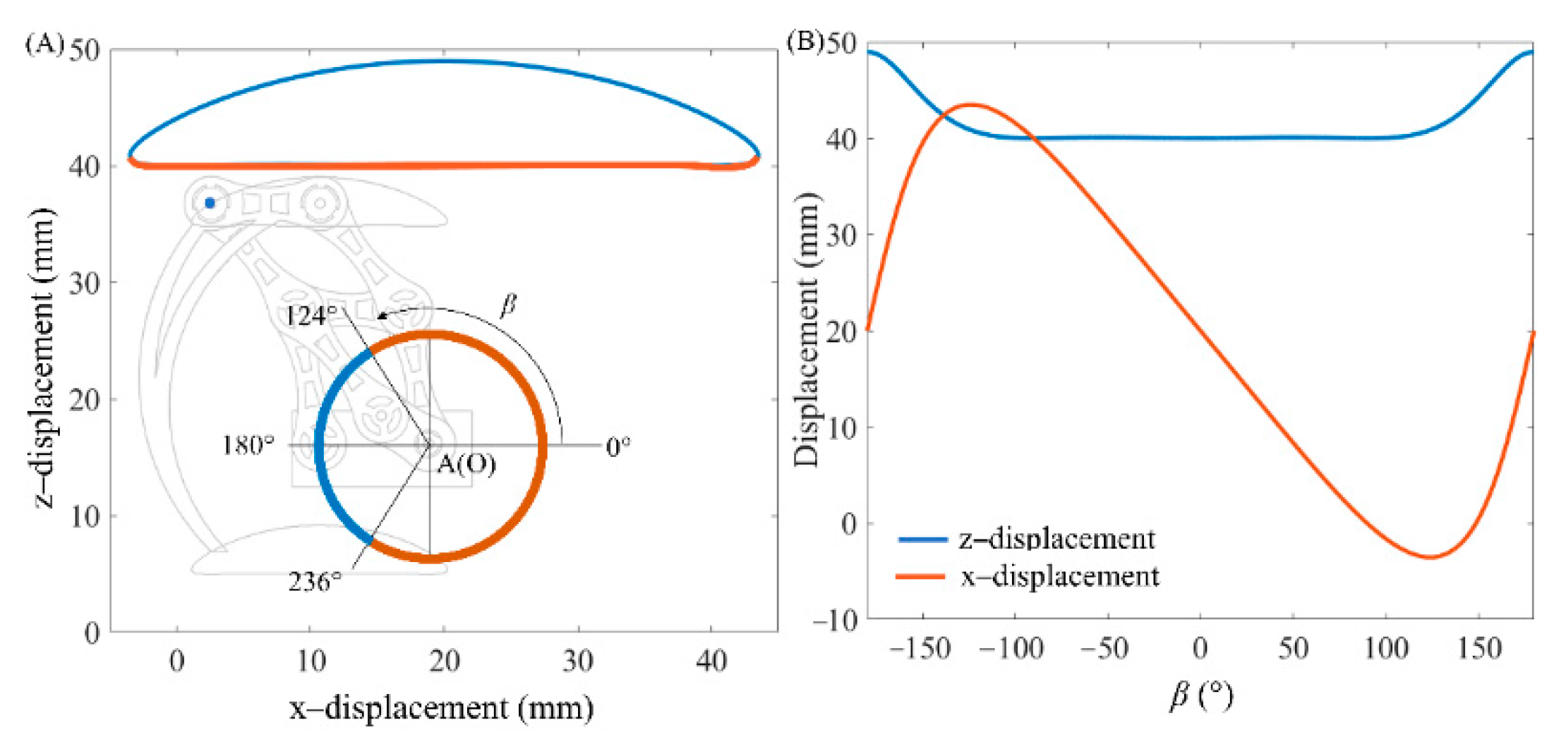
The trajectory of point C is simulated, and the parameters of the rod AB are 10 mm, and the length of other rods satisfies Equation (1). The displacement of point C relative to A is visually displayed in Figure 3. The red and blue curves in Figure 3A correspond to the approximate linear trajectory and the shell curve trajectory, respectively. The relationship between displacement and swing angle can be observed in Figure 3B, and the red and blue curves represent the displacement in the x and z directions, respectively. The swing angle β corresponding to the two curves are and , respectively.
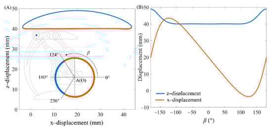
Figure 3.
The displacement of point C relative to point A. (A) Locomotion trajectory of point C relative to point A (the red part corresponds to the leg in a supported state, β: −124°~124°; the blue part corresponds to the leg in a swinging state, β: 124°~236°); (B) horizontal and vertical displacement of point C.
The size parameters l and k of the closed trajectory curve can be obtained by Equations (3) and (4) as follows:
The cycloid and the approximate straight line correspond to the swing phase and the support phase of the leg, respectively. Through two parallel four-bar linkage mechanisms, the trajectory shape of point D is completely consistent with that of point C. The coordinate of point D relative to the origin O of the leg is obtained by Equation (5) as follows:
α is positive in the counterclockwise direction. Specifically, α is 180° and 270° in Figure 2C,D, respectively.
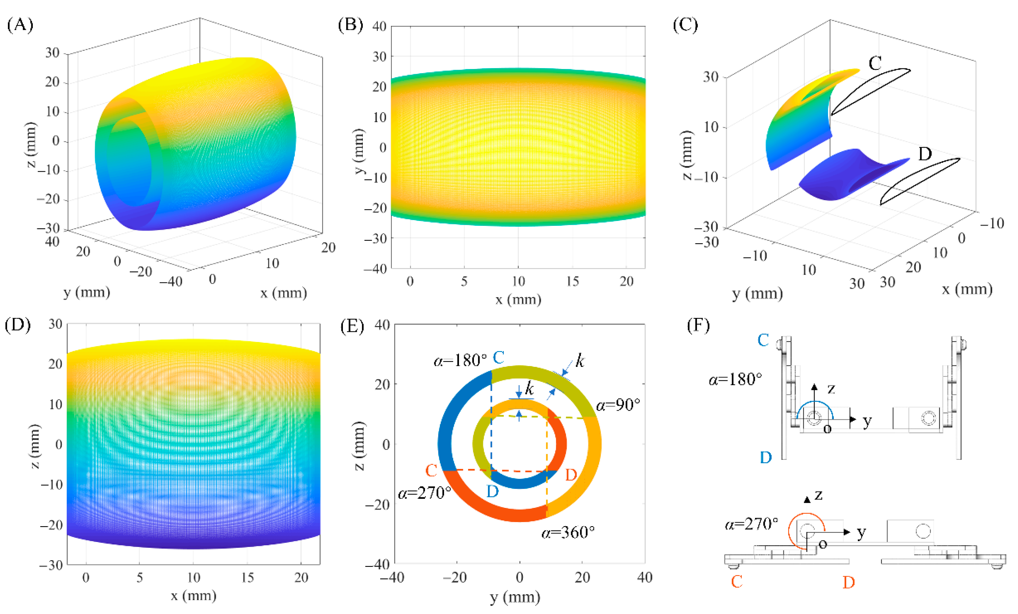
Through kinematic analysis, the working space of the leg can be obtained, as shown in Figure 4. In Equation (5), the value of b is 10.5 mm (in theory, b can take any value). The values of c and d should ensure that the bottom of the robot does not interfere with the ground in the standing state (, α = 180°). c and d are 32 mm and 4 mm, respectively, which are two of the values that meet the requirements, and the rod length parameters are consistent with the above.
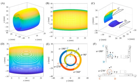
Figure 4.
Working space of one leg. (A) Work space with two support points C and D, with C on the outside and D on the inside; (B) projection of the working space on the x–o–y plane; (C) cross section of working space; (D) projection of the working space on the x–o–z plane; (E) projection of the working space on the y–o–z plane, and the working space position corresponding to the typical robot structure; (F) Two typical postures of crawling robot (α = 180° and α = 270°).
The working space contains the reachable space of two supporting points C and D, the inner and outer areas in Figure 4A, respectively. As shown in Figure 4B,D,E, the working spaces of points C and D are symmetrical in front and back, left and right, and up and down, and the long axis is parallel to the x axis. However, their shapes are different. As shown in Figure 4C, the working space is cut off by a plane perpendicular to x–o–y, and a cross-sectional view of the working space at two points C and D are obtained. The inner surface of the point C working space is a cylindrical surface and the outer surface is an ellipsoidal surface. The shape of the working space at point D is the opposite; the outer surface is cylindrical and the inner surface is ellipsoidal.
The working space can provide a reference for us to analyze the robot’s ability to overcome obstacles and its mobility through narrow spaces. It also shows that the robot configuration supported by point C is suitable for moving on the outer surface of the arc, and the structure supported by point D is suitable for movement on the inner surface of the arc. Theoretically, the leg motors operate alone, and the robot can move on the inner and outer surfaces of the arc. The feasibility of the robot’s motion on the inner and outer arc surface will be analyzed in detail below.
3. Feasibility Analysis of Arc Surface Locomotion
The kinematics and working space of the two supporting points C and D were obtained. When the robot moved on the outer surface of the arc, as shown in Figure 5A, the configuration supported by point C was more advantageous than the configuration supported by point D, because the supporting area in the former was larger and more stable. When the robot moved on the inner surface of the arc, the configuration supported by the D point was more advantageous than the configuration supported by point C, as shown in Figure 5B. Considering the direction of the cycloid in the trajectory, the legs in the latter are likely to interfere with the arc when swinging.

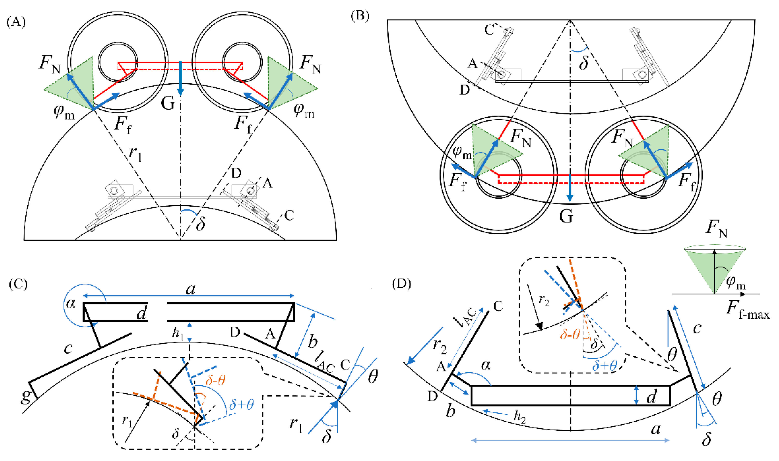
Figure 5.
The robot moves on the inner and outer surfaces of the arc (the arc radius is r1, and the friction angle is φm; the support position and the support posture of the leg are represented by angles δ and θ, respectively). (A) The robot moves on the outer surface of the arc in a creeping posture; (B) the robot moves on the inner surface of the arc with the configuration supported by point D; (C) the meaning of the geometric dimensions that need to be considered when moving on the outer surface; (D) the meaning of the geometric dimensions that need to be considered when moving on the inner surface.
Stable support on the arc without interference is the basis for the robot to move on the inner and outer surfaces of the arc. The self-locking of the robot is the premise on which to avoid sliding on the arc surface. From the six main models of friction summarized by Liu [21], the Coulomb friction model was the most suitable. The arc size, surface friction coefficient, and robot size are important variables. As mentioned above, adding adhesive pads or claws can complement the attachment parts of the robot, and it can also increase the friction coefficient. In order to analyze the influence of surface friction characteristics on locomotion more accurately, we set the friction coefficient as μ, and the friction support angle can be obtained by Equation (6) as follows:
In different positions on the arc surface, if the gravity is always within the friction angle, the robot can achieve self-locking without falling. When the support angle δ of the robot on the arc is less than the friction support angle , the robot can support stably on the arc surface, and the limit boundary is . At this time, the shoulder joint rotation angle α can be obtained by Equation (7) as follows:
The minimum arc radius for crawling (ri, i = 1, 2) is used to represent the size of the arc surface on which the robot can crawl. The parameters that need to be considered are the surface friction angle (φm), the support position of the robot on the arc (δ), and the support attitude of the robot on the arc (). As shown in Figure 5C, the robot crawls on the outer surface of the arc, with point C as the support. The constraint relations in the horizontal and vertical directions are Equations (8) and (9), respectively:
As shown in Figure 5D, the robot moves on the inner surface of the arc with point D as the support. The constraint relations in the horizontal and vertical directions are Equations (10) and (11), respectively:
Among them, and δ are as follows:
For ε, also see Appendix A.
Numerical simulation is carried out where the value of a is 18 mm (a should ensure that the left and right legs do not interfere in the prostrate state (, α = 270°)), and the other parameters are the same as above.
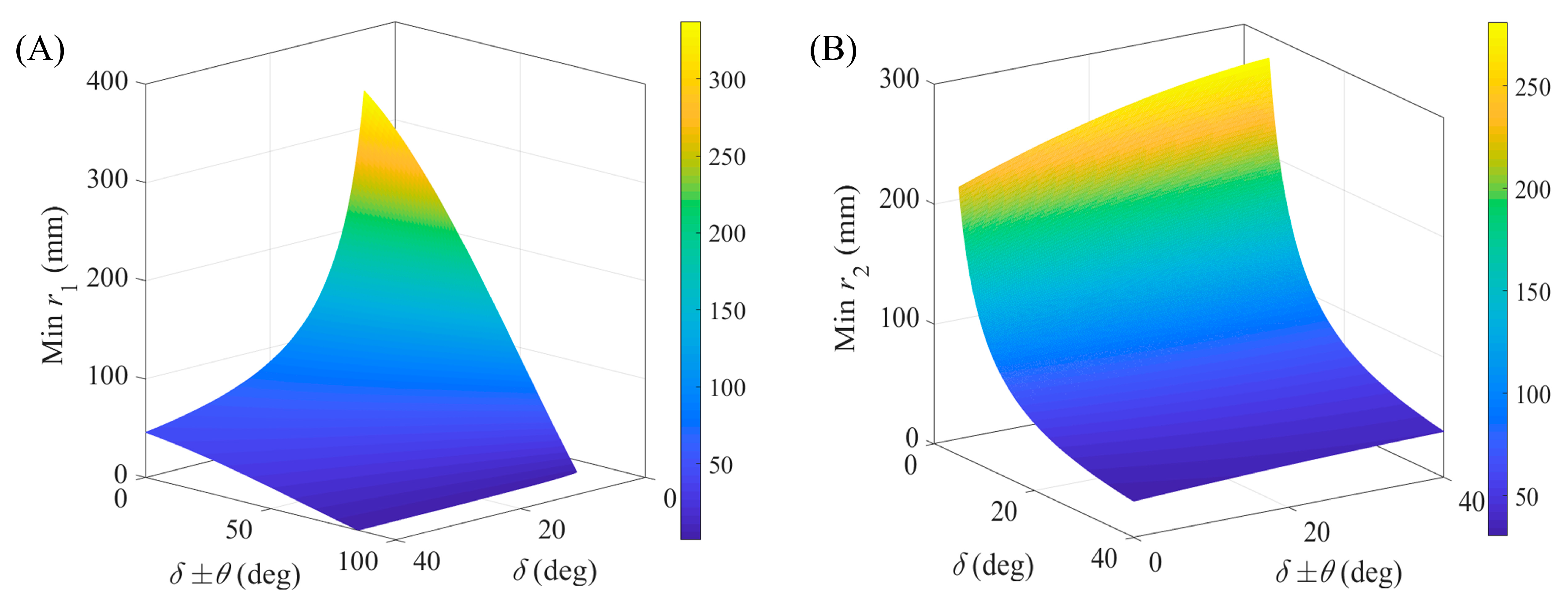
In order to achieve friction self-locking, the robot support position angle is related to the surface friction angle. The larger the surface friction angle, the greater the range of the support position angle. It can be seen from Figure 6A,B that as the surface friction angle φm and support position angle δ increase, the minimum arc radius that can be stably supported significantly decreases. This reveals that the range of arc radius that the robot can adapt to has been significantly expanded. Therefore, for surfaces with a relatively large friction coefficient, the robot can adapt to a wider range of pipe radii, and for very smooth surfaces, the adhesion friction force can be increased by using adhesive pads.
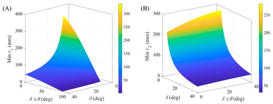
Figure 6.
The relationship between the distance from the robot to the arc surface (hi), the feasible arc radius (ri) and support position (δ), and the leg support posture (θ) (δ ± θ means the angle between the support leg and the vertical line, and the positive and negative signs can be judged in Figure 5). (A) The minimum outer radius arc during crawling, when the friction support angle φm is 40°, and the range of leg support angle is (−40° to 50°); (B) the minimum distance from the bottom of the robot to the outer arc, when the friction support angle φm is 40°, and the range of leg support angle is (−40° to 50°).
As shown in Figure 6A, the support position on the outer surface of the arc satisfies the friction–angle constraint (). The smaller the value of δ ± θ, the smaller the radius of the arc to which the robot can adapt, especially when the surface friction coefficient φm is relatively small, so the robot can only support on the outer surface of the larger arc. The smaller δ ± θ indicates that the robot adopts the retracted posture. The larger δ ± θ means the robot adopts the hugging posture, which is conducive for the robot to move on the outer surface of the arc with various sizes.
As shown in Figure 6B, the support position of the robot on the inner surface of the arc meets the self-locking requirements (). The influence of the support posture is not as significant as when the robot moves on the outer surface. In this simulation, when δ ± θ is less than 40 degrees, the bottom of the robot will not interfere with the arc. This means that the robot adopts an expanded support method, i.e., the legs are outside the line of action of the contact force. When δ ± θ is zero, it can be observed that the robot adopts an upright support and can be applied to a wider range of arc sizes.
In general, the robot must meet the friction–angle constraint and avoid interference in the supporting position. The greater the friction coefficient φm, the closer the support position angle δ is to the friction angle φm, and when the support posture adopts the extended posture, i.e., the support leg is outside the straight line of contact force, the robot can be applied to a wider range of arcs. The range of the leg joint drive angle β in the support state is ; the shoulder joint drive angle α can be obtained by Equation (7).
4. Simulation Test of Robot Locomotion
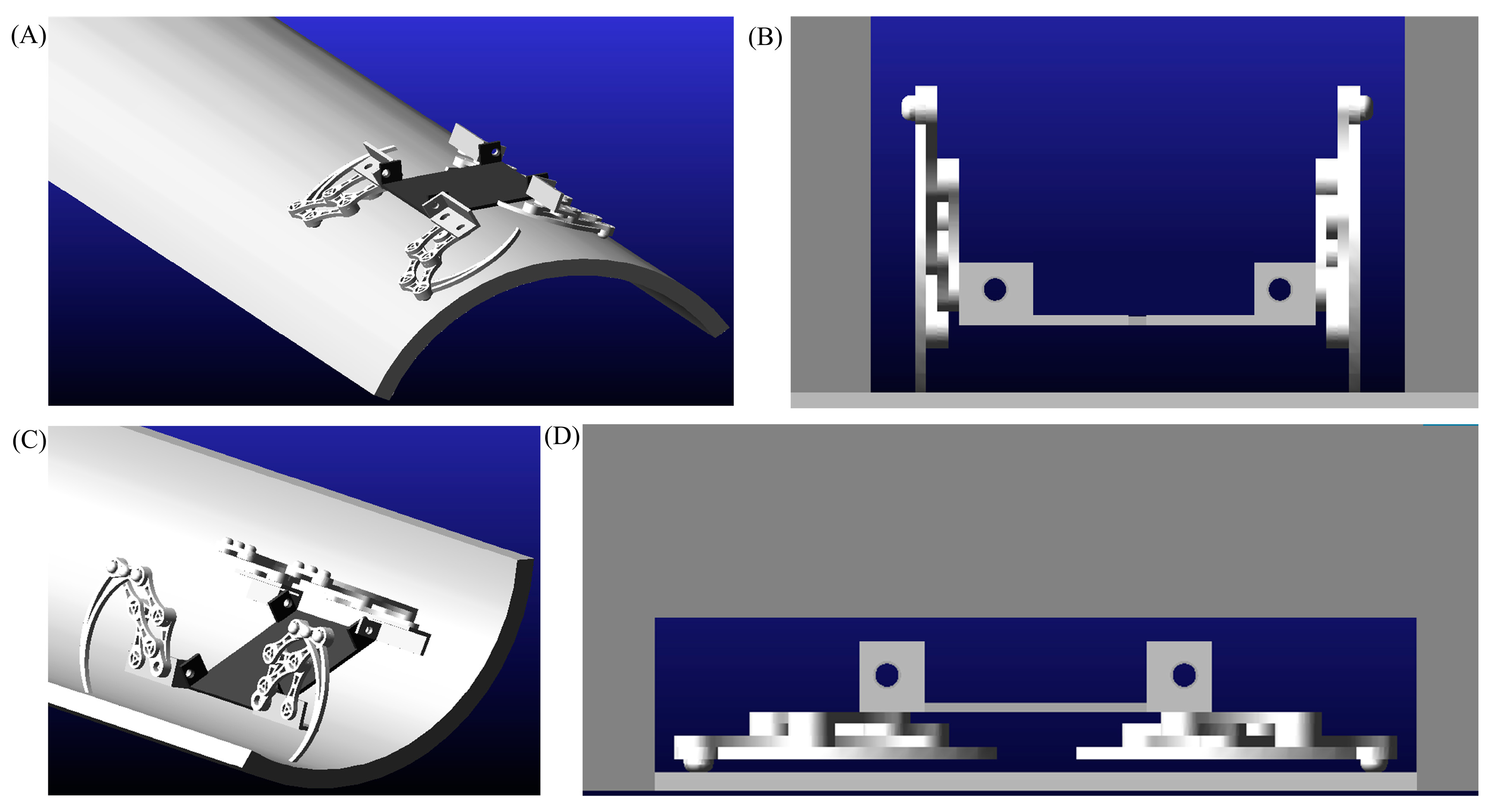
The robot can deform and move on the inner and outer surfaces of the arc in a narrow space. For several typical unstructured environments shown in Figure 1, the virtual test environment was constructed as shown in Figure 7.
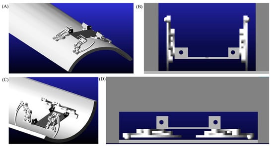
Figure 7.
The robot moves in several unstructured environments as shown in Figure 1. (A) The outer surface of the arc; (B) width-constrained environment; (C) the inner surface of the arc; (D) height-constrained environment.
First, the model was imported into ADAMS using Solidworks software. Then, the material properties (aluminum) and the direction of gravity (z direction) were set; then, kinematic pairs and drives (12 rotary drives) were added; then, the contact parameters (dynamic friction coefficient 0.8, static friction coefficient 0.5) were set between the foot and the ground; finally, the dynamic simulation was conducted (the simulation time is 4 s and the number of steps is 500). Locomotion performance was obtained in the simulation test shown in Figure 8.
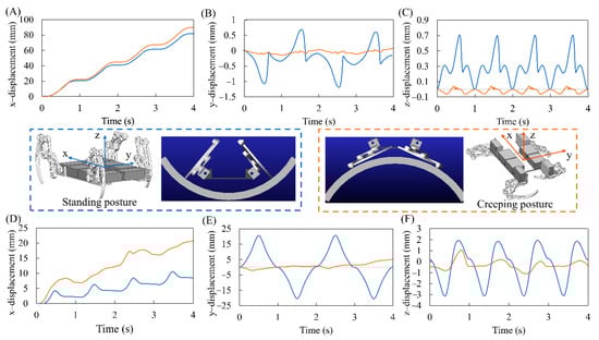
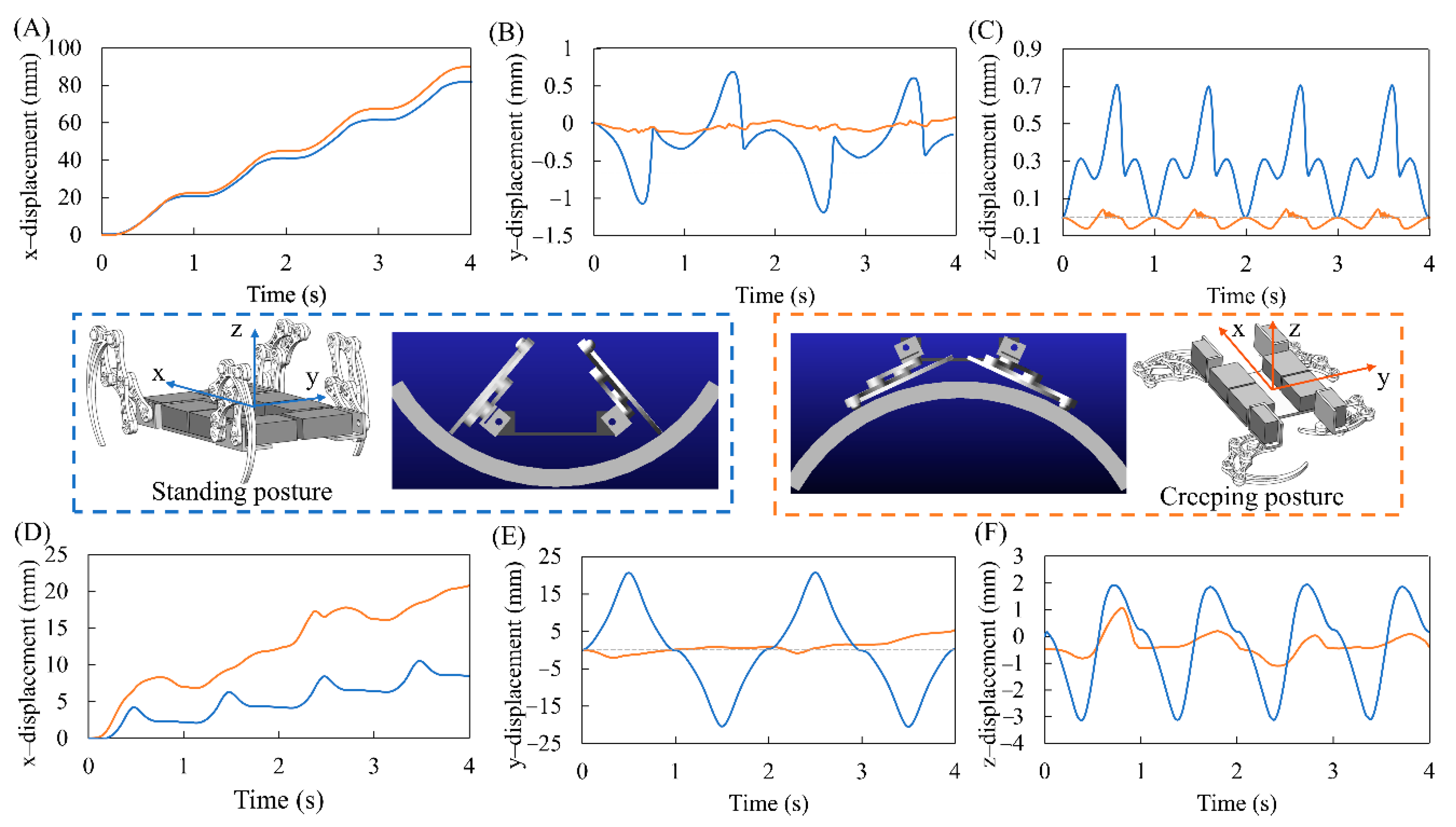
Figure 8.
Simulation analysis of robot locomotion (t blue curve represents the upright state of the limbs, and the red curve represents the prostrate state of the limbs). (A), (B), and (C) are the displacements of the robot in the x, y, and z directions of the plane locomotion, respectively; (D), (E), and (F) are the displacements of the robot in the x, y, and z directions when it moves on the arc surface, respectively (the blue curve represents the locomotion of the inner surface, and the red curve represents the crawling locomotion on the outer surface).
The simulation test results of the robot moving on a plane in two typical configurations are shown in the Figure 8A–C. Under the same driving parameters, there was little difference in motion speed between the two modes. In the standing-motion mode supported by point D, the maximum lateral deviation was around 2 mm, and the maximum up-and-down fluctuation was around 0.7 mm. In the simulation, the length and width of the robot and the height of the center of gravity were A, B, and C, respectively, and the motion was relatively stable. In the creeping-motion mode supported by point C, the lateral deviation did not exceed 0.15 mm, and the ups and downs did not exceed 0.2 mm. Figure 8D,E shows the robot’s locomotion performance on the inner and outer surfaces of the arc, which is clearly inferior to the robot’s planar motion. The robot’s locomotion in the prostrate state (supported by point C) is still more stable than in the standing posture (supported by point D).
5. Conclusions
This paper presents the mechanism design and simulation of a transformable crawling robot inspired by insects, which has a special symmetrical trajectory and deformability. This robot can change its configuration to adapt to an arc and narrow space, and is suitable for detection, search, and rescue missions. The friction coefficient of the surface, the support position on the arc surface, and the support posture affect the range of the arc surface to which the robot can be applied. In addition to increasing friction, controlling the support position and posture of the robot can also improve its application ability. The simulation tested the robot’s movement performance in different environments. The locomotion of the robot in the creeping state was very stable, and future work will focus on developing it for vertical flat/curved surfaces with adhesive pads or claws. Moreover, the installation of sensors (vision or force) and operating systems can assist the robot in recognizing and operating in narrow and unknown environments. While our findings can inspire the locomotion of robots in unstructured environments, there is still a lack of real robot prototypes for the application value of our research, so future work will focus on the fabrication and control of robots.
Author Contributions
Software, Z.Z.; writing—original draft preparation, J.Y.; writing—review and editing, Z.W.; visualization, Y.X.; supervision, A.J.; funding acquisition, Z.W. All authors have read and agreed to the published version of the manuscript.
Funding
This research was funded by National Key R&D program of China (2019YFB1309600) and the Natural Science Foundation of China (51975283).
Institutional Review Board Statement
Not applicable.
Informed Consent Statement
Not applicable.
Data Availability Statement
Not applicable.
Acknowledgments
We are grateful to Yi Song and Qian Li for their assistance with this investigation.
Conflicts of Interest
The authors declare no conflict of interest.
Appendix A
References
- Mongeau, J.M.; Demir, A.; Lee, J.; Cowan, N.J.; Full, R.J. Locomotion- and mechanics-mediated tactile sensing: Antenna reconfiguration simplifies control during high-speed navigation in cockroaches. J. Exp. Biol. 2013, 216, 4530–4541. [Google Scholar] [CrossRef] [PubMed] [Green Version]
- Tucker, D.B.; McBrayer, L.D. Overcoming obstacles: The effect of obstacles on locomotor performance and behaviour. Biol. J. Linn. Soc. 2012, 107, 813–823. [Google Scholar] [CrossRef] [Green Version]
- Kohlsdorf, T.; Biewener, A.A. Negotiating obstacles: Running kinematics of the lizard Sceloporus malachiticus. J. Zool. 2006, 270, 359–371. [Google Scholar] [CrossRef]
- Heitler, W.J. The locust jump. J. Comp. Physiol. 1974, 89, 93–104. [Google Scholar] [CrossRef]
- Li, C.; Pullin, A.O.; Haldane, D.W.; Lam, H.K.; Fearing, R.S.; Full, R.J. Terradynamically streamlined shapes in animals and robots enhance traversability through densely cluttered terrain. Bioinspiration Biomim. 2015, 10, 046003. [Google Scholar] [CrossRef] [PubMed] [Green Version]
- Jayaram, K.; Mongeau, J.M.; Mohapatra, A.; Birkmeyer, P.; Fearing, R.S.; Full, R.J. Transition by head-on collision: Mechanically mediated manoeuvres in cockroaches and small robots. J. R. Soc. Interface 2018, 15, 20170664. [Google Scholar] [CrossRef] [PubMed]
- Jayaram, K.; Full, R.J. Cockroaches traverse crevices, crawl rapidly in confined spaces, and inspire a soft, legged robot. PNAS 2016, 113, E950–E957. [Google Scholar] [CrossRef] [PubMed] [Green Version]
- Leonard, J.J.; Durrant-Whyte, H.F. Simultaneous Map Building and Localization for an Autonomous Mobile Robot. In Proceedings of the Proceedings IROS ’91:IEEE/RSJ International Workshop on Intelligent Robots and Systems ’91, Osaka, Japan, 3–4 November 1991; pp. 1442–1447. [Google Scholar]
- Thrun, S.; Burgard, W.; Fox, D. A real-time algorithm for mobile robot mapping with applications to multi-robot and 3D mapping. In Proceedings of the IEEE International Conference on Robotics and Automation (ICRA), San Francisco, CA, USA, 24–28 April 2000; pp. 321–328. [Google Scholar]
- Lussier Desbiens, A.; Cutkosky, M.R. Landing and Perching on Vertical Surfaces with Microspines for Small Unmanned Air Vehicles. J. Intell. Rob. Syst. 2009, 57, 313–327. [Google Scholar] [CrossRef]
- Lussier Desbiens, A.; Asbeck, A.; Cutkosky, M. Landing, perching and taking off from vertical surfaces. Int. J. Rob. Res. 2011, 30, 355–370. [Google Scholar] [CrossRef]
- Jung, G.-P.; Casarez, C.S.; Lee, J.; Baek, S.-M.; Yim, S.-J.; Chae, S.-H.; Fearing, R.S.; Cho, K.-J. JumpRoACH: A Trajectory-Adjustable Integrated Jumping-Crawling Robot. IEEE-Asme Trans. Mechatron. 2019, 24, 947–958. [Google Scholar] [CrossRef]
- Woodward, M.A.; Sitti, M. Design of a Miniature Integrated Multi-Modal Jumping and Gliding Robot. In Proceedings of the 2011 IEEE/RSJ International Conference on Intelligent Robots and Systems, San Francisco, CA, USA, 25–30 September 2011; pp. 556–561. [Google Scholar]
- Ngoc Thien, T.; Hoang Vu, P.; Park, H.C. Design and demonstration of a bio-inspired flapping-wing-assisted jumping robot. Bioinspiration Biomim. 2019, 14, 036010. [Google Scholar]
- Kim, K.; Spieler, P.; Lupu, E.-S.; Ramezani, A.; Chung, S.-J. A bipedal walking robot that can fly, slackline, and skateboard. Sci. Robot. 2021, 6, eabf8136. [Google Scholar] [CrossRef] [PubMed]
- Chen, S.-C.; Huang, K.-J.; Chen, W.-H.; Shen, S.-Y.; Li, C.-H.; Lin, P.-C. Quattroped: A Leg--Wheel Transformable Robot. IEEE/ASME Trans. Mechatron. 2014, 19, 730–742. [Google Scholar] [CrossRef]
- Shang, H.; Wei, D.; Kang, R.; Chen, Y. Gait analysis and control of a deployable robot. Mech. Mach. Theory 2018, 120, 107–119. [Google Scholar] [CrossRef]
- Ding, W.; Yao, Y.-A. Self-crossing Motion Analysis of a Novel Inpipe Parallel Robot with Two Foldable Platforms. In Proceedings of the Mechanisms, Transmissions and Applications, Aachen, Germany, 3 April 2015; pp. 221–229. [Google Scholar]
- Lu, S.N.; Zlatanov, D.; Ding, X.L.; Molfino, R. A new family of deployable mechanisms based on the Hoekens linkage. Mech. Mach. Theory 2014, 73, 130–153. [Google Scholar] [CrossRef]
- Hernandez, A.; Altuzarra, O.; Petuya, V.; Pinto, C.; Amezua, E. A robot for non-destructive testing weld inspection of offshore mooring chains. Int. J. Adv. Rob. Syst. 2018, 15, 1729881418770532. [Google Scholar] [CrossRef]
- Liu, Y.F.; Li, J.; Hu, X.H.; Zhang, Z.M.; Cheng, L.; Lin, Y.; Zhang, W.J. Modeling and control of piezoelectric inertia-friction actuators: Review and future research directions. Mech. Sci. 2015, 6, 95–107. [Google Scholar] [CrossRef] [Green Version]
Publisher’s Note: MDPI stays neutral with regard to jurisdictional claims in published maps and institutional affiliations. |
© 2022 by the authors. Licensee MDPI, Basel, Switzerland. This article is an open access article distributed under the terms and conditions of the Creative Commons Attribution (CC BY) license (https://creativecommons.org/licenses/by/4.0/).