Article

Development, Optimization, Biological Assays, and In Situ Field Immersion of a Transparent Piezoelectric Vibrating System for Antifouling Applications

1
CEA LETI, University Grenoble Alpes, 38000 Grenoble, France
2
Laboratory MAPIEM, University of Toulon, 83000 Toulon, France
*
Author to whom correspondence should be addressed.
Actuators 2022, 11(2), 47; https://doi.org/10.3390/act11020047
Submission received: 18 November 2021 / Revised: 27 January 2022 / Accepted: 29 January 2022 / Published: 2 February 2022

Abstract

:
This paper presents the development and experimentations of transparent vibrating piezoelectric micromembranes dedicated to protecting immersed measurement instruments from marine biofouling. As any surface immersed is subject to the adhesion and settlement of organisms, especially in seawater, transparent materials quickly become opaque, resulting in deteriorated accuracy for optical sensors. According to this, we developed a transparent vibrating membrane to promote biofouling detachment in order to reduce the data quality drift and the frequency of maintenance operations on deployed optical sensors. In the first part, the design, the materials, and the steps to manufacture demonstrators are described. Then, the electromechanical characterizations of the demonstrators are carried out and interpreted with the support of FEM simulations. The last part describes the laboratory bioassays and the field immersion tests. Laboratory bioassays assess the antifouling potential of the vibrating piezoelectric membranes by exposing their surface to a suspended bacterial solution. In situ assays allow the membrane to perform in the Mediterranean Sea to assess their effectiveness in real conditions. Laboratory bioassays showed a great potential against the adhesion and settlement of a bacterial solution, while in situ tests confirmed the antifouling effect of piezoelectric vibrating micromembrane. Nevertheless, in situ experimentations revealed troubles with the piezo driver actuating the vibrating membranes, and tests should be carried out again with an improved piezo driver to reveal the full potential of the vibrating membranes. These are the first steps to set up an efficient antifouling vibrating system for immersed optical sensors.

1. Introduction

Any immersed surface in aquatic ecosystems, and particularly in seawater, is subject to the adhesion and settlement of organisms, such as bacteria, algae, or invertebrates. This natural and complex process is known as biofouling. When the environmental conditions are met, the adhesion of microorganisms on the materials and their multiplication leads to the formation of a film on the surface of the materials. This formation takes place in several stages and shows a particularly quick development, which starts a few minutes after the immersion [1].
As it systematically occurs, the undesired development of biofouling has a serious impact in many areas. Biofouling leads to an accumulation of biomass, which reduces the effectiveness and shortens the lifetime of submerged objects. Due to biofouling, water sensors need recurrent cleaning maintenance to keep a proper functioning and a constant data quality. This leads to additional charges for the marine industry. Indeed, many structures, such as offshore platforms, ships, piers, or equipment, including subsea moorings, and surface and subsurface vehicles, have incorporated sensors to monitor the aquatic environment, from rivers to the oceans [2]. Water sensors are also used to control drinking water supply networks and to monitor sewage treatment plants. Nowadays, thanks to new technologies, sensors are more accurate, cheaper, and more incorporable to water monitoring systems. The last step to autonomous monitoring systems is an efficient antifouling solution able to protect sensors for the long term, providing a constant data quality [3]. Biofouling severely affects immersed optical sensors and cameras, as it produces opaque artefacts or blurred images, which strongly drifts the data quality. Manufacturers rarely consider biofouling protection when designing optical sensors. The geometries and the materials used are designed for the technical aspects related to measurement or the economic aspects related to production costs. Thus, users incorporate antifouling solutions on their naked sensors to protect them from biofouling.
To remove biofouling from sensors, mechanical wipers, brushes, and shutters are some of the simplest solutions. Brushes and wipers periodically scratch the sensitive surface to clean it [4], and shutters slow the biofouling development by restricting the sunlight and the marine organisms from reaching the optical window. To be effective, these three solutions must be considered during the sensor development phase. However, some companies offer adaptable systems for a wide variety of optical sensors [5]. These mechanical systems must not scratch or damage the sensitive surfaces of the sensors, and they must be easily replaceable because they wear out. In addition, the movements of wipers, brushes, and shutters can interfere with optical measurements. For optical sensors in closed systems, biofouling adhesion could be reduced by adding biocides. Chlorine or bromine could be gradually released from the electrolysis of water to prevent biofouling [6]. This remains ineffective for optical sensors in open systems. As copper generates cuprous Cu2+ ions, which are biocides, copper-coated systems can also be used to inhibit biofouling. On the other hand, previous works showed that copper alone cannot thoroughly avoid biofouling settlement [7]. Biofouling growth could also be inhibited thanks to UV-C irradiation, affecting cells’ DNA, leading to the death of the exposed organisms [8]. Some companies have developed UV modules to protect immersed sensors [9]. These UV modules must fit easily onto the sensors without cluttering them or consuming too much power for stand-alone systems. Other alternatives, such as biocidal antifouling coatings and fouling release coatings, are currently used to protect seawater-immersed surfaces from biofouling. These coatings release biocides in a controlled way, either by erosion of the polymer matrix (SPC) or by dissolution of biocides in water (CDP) [10], or limit biofouling through reduced adhesive forces [11]. These coatings have been developed for the shipbuilding industry and can be transferred to sensors if the released biocides do not interfere with the measurements. In addition, they wear out effectiveness through time and, because most of them are not transparent, these coatings are not suitable to protect optical sensors from biofouling.
Other antifouling strategies are under development as acoustic waves used to promote biofouling detachment [12]. This technology is mainly used in ballast tanks of ships, pipelines, and, in a lesser extent, on ship hulls. It is declined in two sub-categories, depending on the vibration frequencies: ultrasonic (>20 kHz) or audible (20 Hz–20 kHz). Devices transmit mechanical waves into the hull of a vessel or into a pipe thanks to a signal generator, an amplifier, and a transducer, which can be magnetic [13] or piezoelectric [14]. This technology can be effective but requires significant power [15,16,17,18], making it not yet suitable for protecting immersed optical sensors.
Therefore, there is a need to develop efficient antifouling solutions to reduce the optical sensor maintenance and the cleaning operations. Previous works showed that living organisms could be handled using low vibration amplitudes [19]. Other works investigate the ability of a fluidic cell holding device to detach living microorganism from an oscillating substrate. A piezoelectric actuator attached at the base of the cell holding device is utilized to provide a detachment force to overcome adhesion force and hydrodynamic forces of the living microorganism. The results reveal that the detachment force is determined by both vibration frequency and amplitude [20]. According to this, vibrating surfaces can promote biofouling detachment and even prevent the settlement of living microorganisms when the vibration frequency and amplitude are well suited. For example, the biofouling growth was shown to be inhibited using vibrating plates actuated with poly(vinylidene fluoride) (PVDF) as a piezoelectric device [21,22]. These latter works studied the expansion of biofouling on a vibrating glass plate immersed in the Mediterranean Sea and actuated by PVDF actuators. Although the results showed an antifouling effect as soon as the glass plate vibrated with a modal acceleration higher than 0.2 g, this system has not been directly adapted to immersed optical sensors because of technical limitations. First, the glass plate size 0.16 × 0.15 m2 is large compared to the window of optical sensors. Then, this vibrating plate is driven by PVDF. This polymer has a low piezoelectric coefficient d31 = 23 pC/N, limiting the vibration amplitudes, and it has a low breakdown field, which does not allow the actuation voltage to be increased much without tripping the system. Accordingly, the vibration amplitudes of the glass plate are only about 0.13 nm for an actuation voltage of 2.5 V. To protect immersed optical sensors efficiently, the vibrating plate could have been smaller and driven by lead zirconate titanate piezoelectric ceramic (PZT), which shows a large piezoelectric coefficient d31 = 167 pC/N [23], as well as a large breakdown field compared to PVDF. According to this, we developed transparent vibrating membranes based on PZT actuators to allow larger vibration amplitudes, and thus expect a larger antifouling effect. The PZT actuators that attach to the portholes of immersed optical sensors could be used to limit or even prevent the biofouling. The next part of this paper presents the development and electromechanical characterizations of our transparent piezoelectric vibrating membranes. Finally, this article shows the first laboratory bioassays and field immersion tests, which prove the potential of the vibrating approach for antifouling application.

2. Materials and Methods

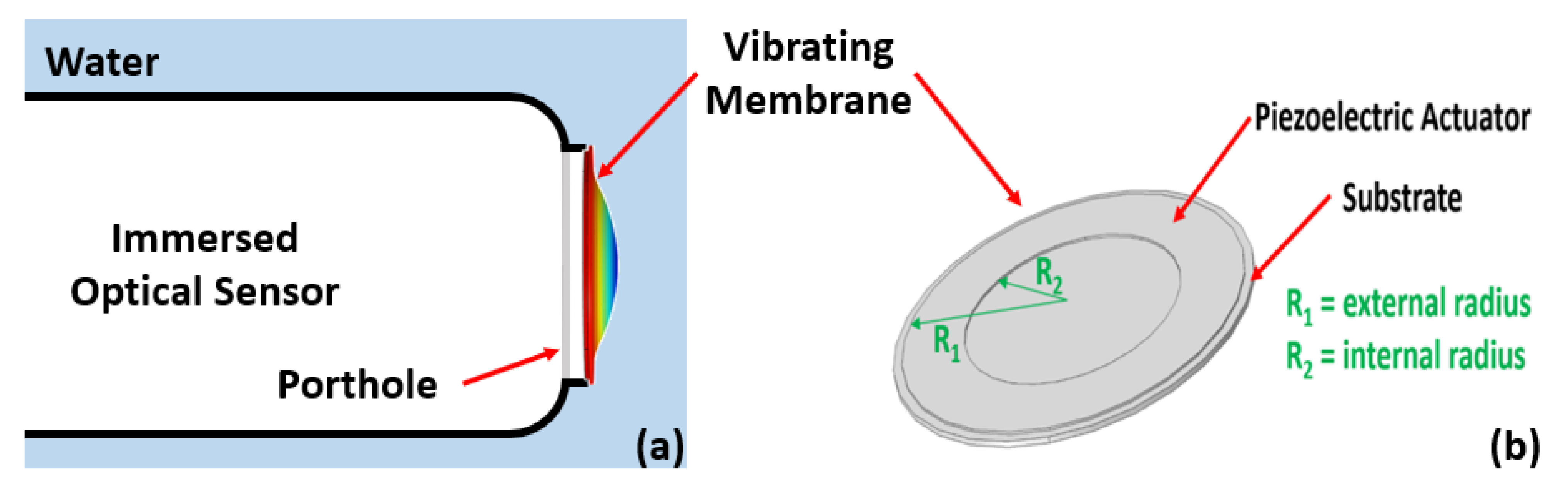
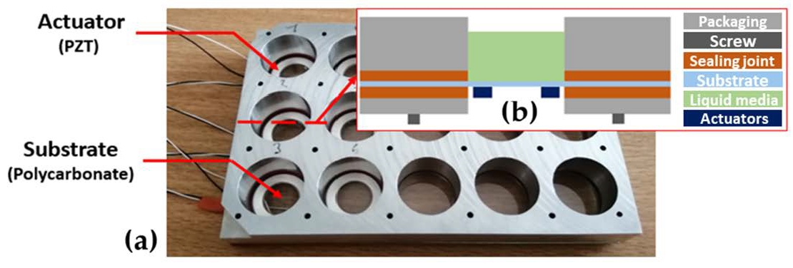
2.1. Fabrication and Design

Research on marketed optical sensors showed that the sensitive surfaces to protect are commonly circular and size less than 5 mm in radius. Thus, we developed transparent circular vibrating micromembranes actuated by an annular piezoelectric actuator with an internal radius sizing of at least 5 mm. Figure 1 shows a schematic view of the vibrating membrane principle, as well as the vibrating membrane main parts and dimensions. R2 represents the actuator’s internal radius and R1 represents the actuator’s external radius and, consequently, the membrane radius.
Thanks to finite element method (FEM) simulations carried out using COMSOL Multiphysics® (COMSOL France SAS, Grenoble, France), the membrane and actuator dimensions were optimized to maximize the deflection of the vibrating membrane. The vibrating antifouling system consists of a 250 µm thick polycarbonate (PC) micromembrane. In our model, the membrane is clamped on its periphery. A 200 µm thick PZT (PZT-4) actuator is stacked above the PC membrane. We neglected top and bottom electrodes on both sides of the PZT layer due to their low impact on the membrane displacement amplitude. Figure 2 shows the normalized deflection of the simulated membrane depending on the ratio r =   R 2 / R 1 .
Thus, a ratio r of about 50% allows the membrane to vibrate with the highest displacement amplitude. Moreover, the thinner the actuator is, the lower the actuation voltage will be to reach a given deflection. To make the vibrating membranes, we use PZT actuators manufactured by PI Ceramic GmbH®. These actuators have an internal radius R2 of 6 mm, an external radius R1 of 9.5 mm, a thickness of 0.2 mm, and they are made from the PIC155® (PI Ceramic GmbH®, Lederhose, Germany) material [24]. The ratio r is about 63%, close to the optimal one. The PC sheet is a 250 µm thick Makrofol® DE 1-1 (Covestro®, Leverkusen, Germany) [25].
The PZT rings were glued on the PC sheet thanks to the Vitralit® 7989 (Panacol-Elosol GmbH®, Steinbach, Germany) UV adhesive [26] and a UV light. Then, the electrical connectors were welded on the electrodes of the actuators. Then, the PC sheet was packaged to form 15 wells. These wells ensure the clamping of the piezoelectric membranes, which is a required condition to make them vibrate. In addition, the wells were sealed at the base, allowing them to hold liquid to perform biological assays. To assess the antifouling effect of vibrations, the packaging hosts 6 vibrating membranes and 9 nonvibrating membranes, allowing comparison. Figure 3 shows a photography of the packaged membranes and a cross-section diagram of the packaged vibrating membrane.

2.2. Electromechanical Characterizations

Prior to assessing the effect of vibrations on the biofouling, it is required to know the electromechanical behavior of the vibrating membranes. Mechanical behavior of a flat circular plate is well known and reported in the literature [27,28]. Such a plate resonates at several proper frequencies, resulting in various modes of deformation. The purpose of the electromechanical characterizations is to assess the mechanical response of our vibrating membranes under various actuation conditions of the PZT actuator. Thus, characterizations were performed using a MSA400® Laser Doppler Vibrometer (Polytec GmbH®, Waldbronn, Germany). The out-of-plane resonant modes were studied for each vibrating membrane between 100 Hz and 8000 Hz, with an electrical signal of 10 V actuating the piezoelectric ring. The measurements were first performed in air media as each well was empty, then in water media as each well was filled with 1.9 mL of water. Figure 4 shows one of the resonance spectra recorded for the same vibrating membrane, in air and in water media.
There are two modes of resonance for each medium in the considered frequency range. The first mode is at 2656 Hz in air and 809.4 Hz in water, while the second mode is at 5793 Hz in air and 2600 Hz in water. The first observation is that the frequency of a resonance mode decreases by going from air to liquid medium. As vibrating membranes are resonant systems, the proper frequency of each mode can be determined by the equation f = 1 2 π × k m [29]. According to this equation, the frequency of a resonance mode is inversely proportional to the mass of the system. As the water acts as an added mass on the vibrating membranes, the resonant frequency of a mode shifts in contact with water due to a damping effect on the resonant system. The second observation focuses on the evolution of the resonance spectrum while switching medium. Both peaks show higher displacement amplitudes and look shaper in the water medium compared with the air one. The shaper the peaks, the greater the quality factor, resulting in lower energy loss rates and slower decaying oscillations, justifying higher vibration amplitudes in water medium. If immersed resonating devices, such as cantilevers, commonly show a deteriorated quality factor when going from air to liquid medium, it is already reported in the literature that the quality factor of a plate can increase by switching from air to water medium, under certain conditions [30,31]. In particular, this is because the quality factor takes into account the kinetic energy of the fluid, which is higher in water than in air, and because the membranes are operating far below the critical frequency required to efficiently radiate longitudinal waves into the water [31]. This may also potentially be due to nonmonotonic energy dissipation phenomena [32].
According to FEM simulations, it appears that the change in medium evolves the frequency of each mode but does not alter their shape. For an efficient antifouling effect, we will focus on the first resonance mode, due to its dome shape and the greatest deviation in the middle of the membrane. Table 1 records the frequency of the first resonance mode of each membrane and the related deflection under a 10 V actuation voltage, both in air and water media.
Electromechanical measurements evidenced that going from an air medium to a water one, makes the deflection evolve upwards. This can be explained by the effect of displaced water due to the membrane vibration.
As the bacterial adhesion test will be performed in water, we focused on the vibrating membranes’ behavior in this medium. The average frequency of the first vibration mode is 789.6 Hz, with an acceptable dispersion of 7.5%. Moreover, a low actuation voltage of only 10 V allows a high deflection amplitude of at least 8 µm, at the middle of the membrane, which is promising to promote an antifouling effect. Finally, during the bacterial adhesion test, the membranes will be actuated at the average frequency of 789.6 Hz.

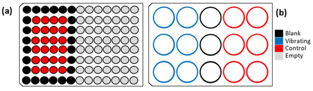
2.3. Bacterial Adhesion Test

The biological test described below is carried out in a sterile environment, with disinfected equipment and under controlled air flow to avoid external contamination. The bacterial strain used for bioassays is the marine bacteria TC8 (Pseudoalteromonas lipolytica [33]), which was isolated in Toulon Bay (Mediterranean Sea, February 2008) from an artificial surface. This bacterial strain is Gram-negative and classified as hydrophilic bacteria. Firstly, the cryogenicist TC8 strain is spread on Petri dishes that are placed in incubation at 20 °C for 3 days. Afterwards, the bacteria are transferred from the Petri dish to vials filled with Vaätanen nine-salt solution (VNSS), which is a nutritional liquid. The vials are placed in an incubator set at 20 °C with a stirring speed of 120 rpm to avoid sedimentation of the suspended bacteria. Under these conditions, the suspended bacteria grow freely for 24 h; this step is known as preculture. Then, a small volume of the preculture is taken to inoculate a new sterile VNSS vial. This is the culture step. During this step, the development of bacteria is monitored by measuring the optical density of the culture medium at the wavelength of 600 nm (OD600nm). The culture step starts with an OD600nm = 0.1 and ends when the OD600nm reaches a stationary phase between 0.7 and 0.9, usually after five or six hours.
The bacterial suspension is then centrifuged (15 min, 6000× g) to gather the bacteria in a pellet. The supernatant is discarded and replaced by artificial sea water (ASW, Sigma-Aldrich®). In this nutrient-poor medium, the bacteria adapt to survive by adhering to surfaces and forming a biofilm. At this point, we fill the wells of the packaged membranes and wells of a 96-well microplate (Tecan Systems®, 96-well microplate, black, flat bottom, n°30122298) with the TC8 suspension (1.9 mL and 200 µL, respectively). The microplate is used as a positive control of adhesion on artificial surfaces. Figure 5 shows the filling diagram of the plates.
The vibrating and control wells hold the ASW bacterial suspension, while the blank wells hold sterile ASW to calibrate the measuring instrument. Both plates are covered to avoid evaporation and incubated at 20 °C with a stirring speed of 120 rpm. The vibrating membranes are actuated thanks to an MFG-2160MR® function generator (GW INSTEK®, New Taipei City, Taiwan) and a PDM200b® piezo driver amplifier (PiezoDrive®, Shortland, Australia). To actuate the vibrating membranes, the generator delivers a 10 V sinusoidal signal of frequency 789.6 Hz, which corresponds to the average frequency of the first vibration mode while the wells are filled with 1.9 mL of water. To increase the deflection of the vibrating membranes, the PDM200b® piezo driver can amplify the sinusoidal signal up to a voltage of 121.6 V. The experimentation lasts for 16 h.
After 16 h, the wells are washed three times with ASW to remove non-adhered bacteria. To quantify adhered bacteria, we use a fluorescent nucleic acid stain, Syto61® (Thermo Fisher Scientific®, Waltham, USA). The fluorescence intensity (FI) emitted by the adhered bacteria in each well is recorded with the Infinite 200® microplate reader (Tecan Trading AG®, Männedorf, Switzerland). FI in the reference wells integrate the whole surface of the well. The ratio of FI between the control wells and the blank wells provides information about the quality of the bacterial adhesion. As the packaged membranes have large wells, 9 points were measured, distributed in a cross shape for each well, as schematized in Figure 6. This will allow adhesion between the area that displayed differential deformation to be distinguished.
The adhesion rate of TC8 bacteria for the vibrating and control membranes was calculated as follows:
% adhesion on vibrating membrane = (FI vibrating − FI Blank)/(FI Control − FI Blank)
% adhesion on control membrane = (FI Control − FI Blank)/(FI Control − FI Blank) = 100%

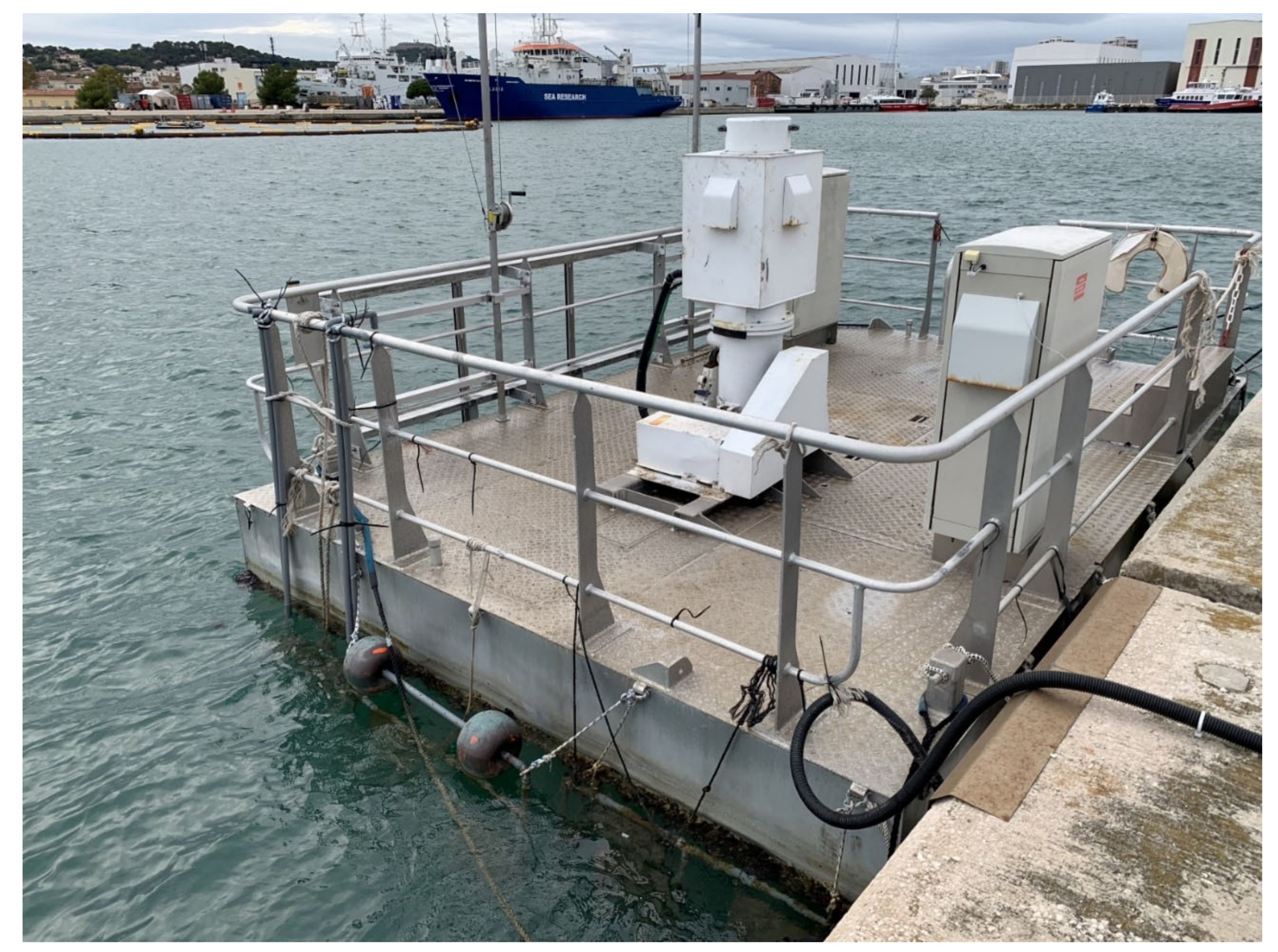
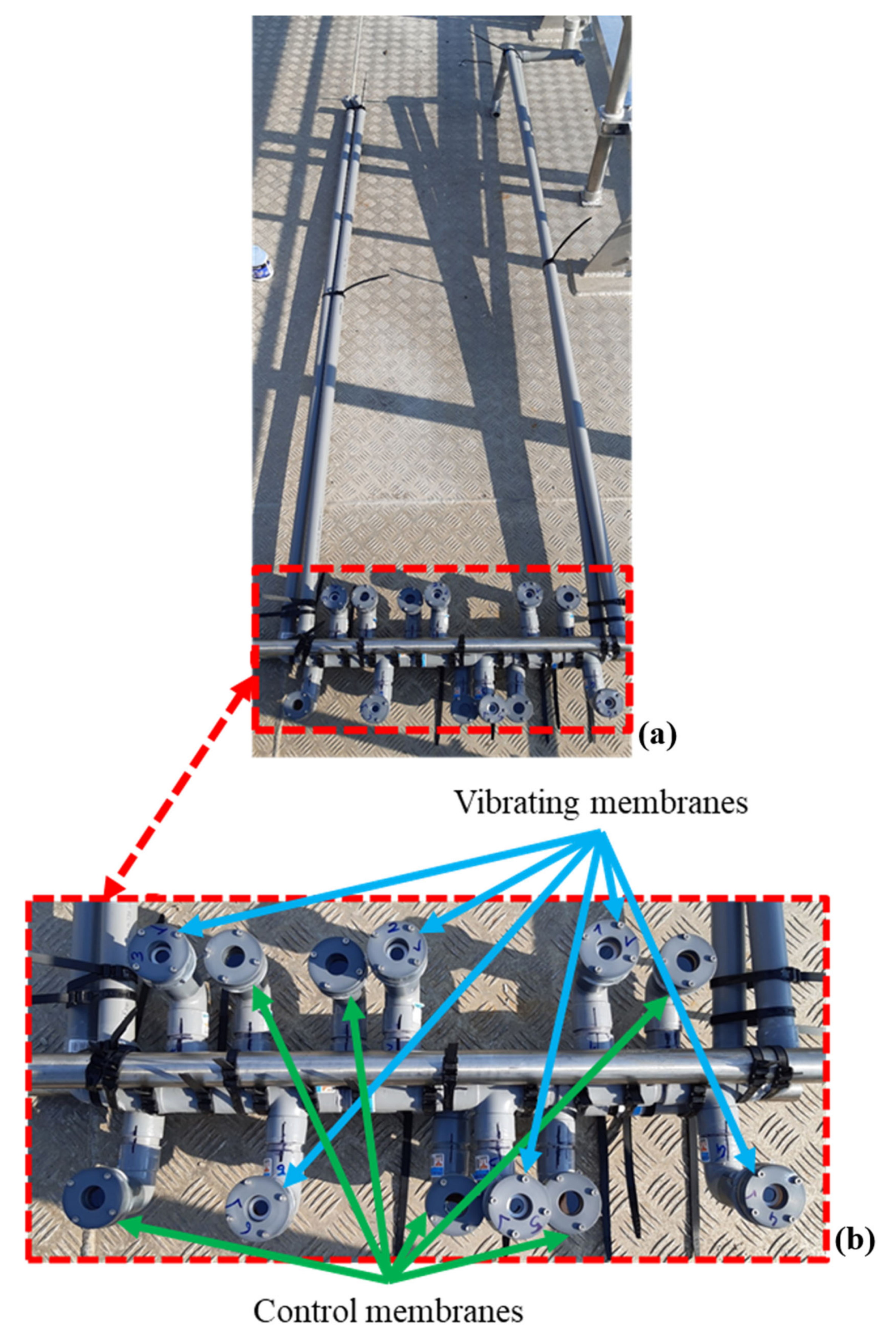
2.4. In Situ Immersion Test

The in situ immersion test described below was conducted in the bay of Toulon, in the French Northwestern Mediterranean Sea, in September 2020. The immersion was performed on a floating platform for a period of five weeks. Figure 7 shows the floating platform.
The vibrating membranes tested were similar to those manufactured for the laboratory bioassays. A polyvinyl chloride (PVC) waterproof structure holds the vibrating and control membranes and allows them to be immersed to a depth of 50 ± 10 cm. The deeper the membranes are, the more pressure they face and the more the resonant frequency of a considered vibration mode decreases. Thus, electromechanical characterization tests were carried out in order to assess the behavior of the vibrating membranes at such a depth. The first resonance mode is, on average, at 595 Hz; the vibrating membranes will therefore be activated at this frequency to recover a dome-shaped deformation. The vibrating membranes are actuated thanks to a DRV2667EVM-CT® piezo driver (Texas Instruments France®, Issy-les-Moulineaux, France), which can deliver a sinusoidal signal of frequency 595 Hz and 42.4 V voltage. Evolution of the biofouling on the vibrating and control membranes is photographed every week to evaluate the effect of the vibrations in real conditions. Figure 8 shows the in situ device, ready to be immersed.

3. Results and Discussion

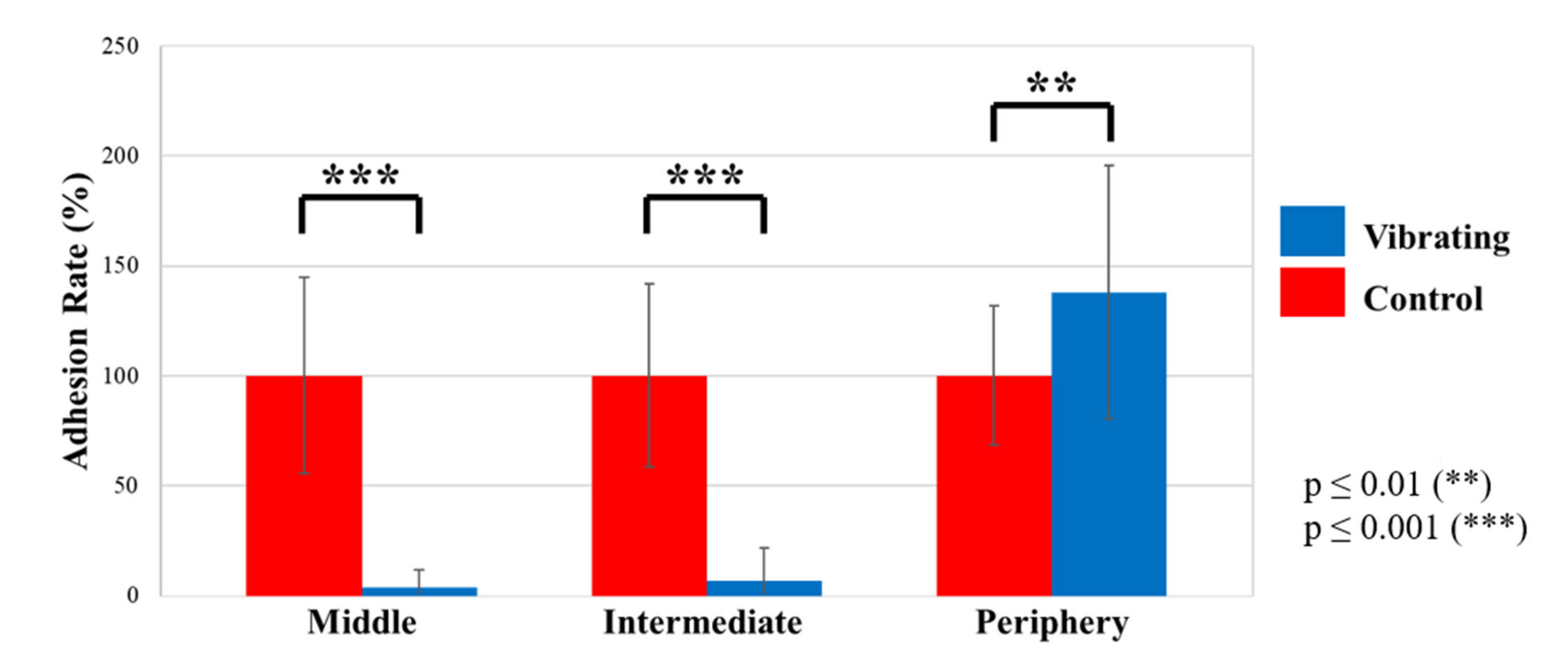
3.1. Biological Assays

The ratio of FI between the control wells and the blank wells is about 14.9, which means that bacteria adhered normally on the bottom of each well and the results of the packaged membranes are exploitable.
For each zone of the membranes, the average of adhered bacteria is compared between the vibrating membranes and the control membranes to evaluate the antiadhesion effect of vibrations.
Figure 9 and Table 2 show that vibrations reduce the adhesion of bacteria by 96.1 ± 7.9% in the middle of the membrane and by 93.5 ± 15.1% on the intermediate area. However, vibrations increase bacteria adhesion on the periphery up to 195.4%. Thus, bacteria are strongly driven from the middle to the periphery of the membrane thanks to vibrations. The antifouling effect depends on the observed zone of the well and it can be related to the deformation shape of the vibrating membrane. As observed during the electromechanical characterization, when actuated at the first mode frequency, the membrane deforms in a dome shape. In this way, the vibrations are important in the middle, moderate on the intermediate area, and null on the periphery. In the end, we can affirm that biological tests show an antifouling effect on the bacterial strain TC8 when exposed to vibrating membranes for about 16 h in comparison to conventional membranes. The vibrating membranes could be a game changer to protect immersed optical sensors from biofouling. The next step is to assess their effectiveness in real conditions while immersed in seawater.

3.2. In Situ Assay

Figure 10 shows the evolution of the biofouling on a vibrating and a control membrane for five weeks. Two distinctive characteristics are observable: first, a green/brown sludge, including probably diatoms and algae, recovered the whole device, membranes, and frame. Then, tubeworms were observed in the cavity holding the membrane.
Figure 10 shows the effect of vibrations on the development of biofouling under real conditions. The vibrating membranes inhibit the biofouling expansion. By analyzing the photography of the biofouling on the vibrating and control membranes over five weeks, it appears that vibrations delay the growth of the green/brown sludge and tubeworms by about one week. These observations are the proof of concept of the antifouling effect of piezoelectric vibrating membranes in real conditions. However, the observed effect remains to be qualified. The piezo driver DRV2667EVM-CT® showed reliability problems and needed to be reset after a few days of immersion. The vibrating membranes, therefore, worked in degraded mode for several days during the five weeks of testing, which reduced their antifouling potential. In addition, the voltage delivered by the piezo driver was only 42.4 V, putting a curb on the vibration’s amplitude on the membranes. The experiment must, therefore, be repeated with a more reliable and powerful piezo driver to ensure that the membranes vibrate without interruption and with greater amplitudes. It is also necessary to redesign the membranes to reduce, or even remove, the cavity that maintains the membrane to not favor the growth of tubeworms. Finally, sensors will have to be added behind the vibrating and control membranes to follow the evolution of biofouling on each membrane with quantitative data. These sensors could be luminosity sensors, for example.

4. Conclusions

Numerous immersed sensors are used for water monitoring and there is a need to protect them, especially submerged optical sensors, from biofouling. A concept of a piezoelectric vibrating antifouling micromembrane has been dimensioned and made using PZT piezo ceramic integrated onto a polymer foil. The prototype of vibrating antifouling membranes has been characterized electromechanically. In water medium, the average frequency of the first vibration mode is 789.6 Hz and, under a 10 V actuation voltage, the average membrane deflection is about 11.47 µm at the middle of the membranes. The membranes were used in laboratory bioassays to evaluate their antifouling potential on a bacterial strain. Tests showed that vibrating membranes reduce the number of bacteria adhering to the middle of their surface by at least 88.2%. Then, the vibrating membranes were integrated on an in situ device and tested in real conditions in the Mediterranean Sea for a period of five weeks. The in situ immersion showed that the vibrations delayed the growth of the biofouling by about one week, showing the antifouling potential of the vibrating membranes in real conditions. The piezo driver actuating the in situ membranes were power limited, so the vibrating membranes were driven with a low voltage compared to the allowable voltage the vibrating membranes could withstand. New in situ tests will be carried out at higher voltage thanks to a new piezo driver, in order to increase the antifouling performance of the vibrating membranes. Therefore, these first results prove the antifouling effect and all the potential of vibrating micromembranes, that could be a possible solution to protect immersed optical sensors efficiently, durably, and with reduced maintenance.

Author Contributions

Conceptualization, F.C. and L.G.; methodology, F.C. and L.G.; validation, F.C., H.B., C.B., R.B.-M., J.-F.B. and M.C.; data curation, F.C.; writing—original draft preparation, L.G.; writing—review and editing, F.C., H.B., C.B., R.B.-M., J.-F.B. and M.C.; visualization, L.G.; supervision, F.C.; project administration, M.C. All authors have read and agreed to the published version of the manuscript.

Funding

This research received no external funding.

Institutional Review Board Statement

Not applicable.

Informed Consent Statement

Not applicable.

Data Availability Statement

Data sharing not applicable.

Conflicts of Interest

The authors declare no conflict of interest.

References

  1. Haras, D. Biofilms et altérations des matériaux: De l’analyse du phénomène aux stratégies de prévention. Mater. Tech. 2005, 93, 27–41. [Google Scholar] [CrossRef]
  2. Delauney, L.; Compère, C.; Lehaitre, M. Biofouling Protection for Marine Environmental Sensors. Ocean. Sci. 2010, 6, 503–511. [Google Scholar] [CrossRef] [Green Version]
  3. Manov, D.V.; Chang, G.C.; Dickey, T.D. Methods for Reducing Biofouling of Moored Optical Sensors. J. Atmos. Ocean. Technol. 2004, 21, 958–968. [Google Scholar] [CrossRef] [Green Version]
  4. Joslin, J.; Polagye, B. Demonstration of Biofouling Mitigation Methods for Long-Term Deployments of Optical Cameras. Mar. Technol. Soc. J. 2015, 49, 88–96. [Google Scholar] [CrossRef] [Green Version]
  5. Zebra Tech. Hydro-Wiper. Available online: https://www.zebra-tech.co.nz/hydro-wiper/ (accessed on 28 January 2022).
  6. Davis, R.F.; Moore, C.C.; Zaneveld, J.R.V.; Napp, J.M. Reducing the effects of fouling on chlorophyll estimates derived from long-term deployments of optical instruments. J. Geophys. Res. Ocean. 1997, 102, 5851–5855. [Google Scholar] [CrossRef]
  7. Soldo, D.; Hari, R.; Sigg, L.; Behra, R. Tolerance of Oocystis nephrocytioides to copper: Intracellular distribution and extracellular complexation of copper. Aquat. Toxicol. 2005, 71, 307–317. [Google Scholar] [CrossRef] [PubMed]
  8. Zheng, J.; Feng, C.; Matsuura, T. Study on reduction of inorganic membrane fouling by ultraviolet irradiation. J. Membr. Sci. 2004, 244, 179–182. [Google Scholar] [CrossRef]
  9. UV_Xchange-AML Oceanographic. Available online: https://www.subseatechnologies.com/aml-oceanographic/bio-fouling/uv-xchange/ (accessed on 28 January 2022).
  10. Almeida, E.; Diamantino, T.C.; de Sousa, O. Marine paints: The particular case of anti-fouling paints. Prog. Org. Coat. 2007, 59, 2–20. [Google Scholar] [CrossRef]
  11. Lejars, M.; Margaillan, A.; Bressy, C. Fouling release coatings: A nontoxic alternative to biocidal anti-fouling coatings. Chem. Rev. 2012, 112, 4347–4390. [Google Scholar] [CrossRef]
  12. Legg, M.; Yücel, M.K.; De Carellan, I.G.; Kappatos, V.; Selcuk, C.; Gan, T.H. Acoustic methods for biofouling control: A review. Ocean Eng. 2015, 103, 237–247. [Google Scholar] [CrossRef]
  13. Stutt, G.A.; Jones, P.H. Marine Anti-Fouling System Using Ultrasonics. WO 2006/045161 A1, 4 May 2006. [Google Scholar]
  14. Choi, C.H.; Scardino, A.J.; Dylejko, P.G.; Fletcher, L.E.; Juniper, R. The effect of vibration frequency and amplitude on biofouling deterrence. Biofouling 2013, 29, 195–202. [Google Scholar] [CrossRef]
  15. Sheherbakov, P.S.; Grigor’yan, F.Y.; Pogrebnyak, N.V. Distribution of high-frequency vibration in hulls of krasnograd-class ships equipped with ultrasonic antifouling protection systems. In Transactions. Technical Operations of the Maritime Fleet. Thermochemical Studies. Control of Corrosion and Fouling. Central Scientific Research Institute of the Maritime Fleet No. 160, 1972; Defense Technical Information Center: Fort Belvoir, VA, USA, 1974. [Google Scholar]
  16. Bott, T.R. Biofouling Control with Ultrasound. Heat Transf. Eng. 2000, 21, 43–49. [Google Scholar] [CrossRef]
  17. Guo, S.; Lee, H.P.; Khoo, B.C. Inhibitory effect of ultrasound on barnacle (Amphibalanus amphitrite) cyprid settlement. J. Exp. Mar. Biol. Ecol. 2011, 409, 253–258. [Google Scholar] [CrossRef]
  18. Kitamura, H.; Takahashi, K.; Kanamaru, D. Inhibitory Effect of Ultrasonic Waves on the Larval Settlement of the Barnacle, Balanus amphitrite in the Laboratory. Mar. Fouling 1995, 12, 9–13. [Google Scholar] [CrossRef] [Green Version]
  19. Debavelaere-Callens, D.; Peyre, L.; Campistron, P.; Hildebrand, H.F. On the use of ultrasounds to quantify the longitudinale threshold force to detach osteoblastic cells from a conditioned glass substrate. Biomol. Eng. 2007, 24, 521–525. [Google Scholar] [CrossRef]
  20. Bahadur, I.M.; Mills, J.K. Fluidic Vacuum-Based Biological Cell Holding Device With Piezoelectrically Induced Vibration. In Proceedings of the 2011 IEEE/ICME International Conference on Complex Medical Engineering, Harbin, China, 22–25 May 2011. [Google Scholar]
  21. Rahmoune, M.; Tarico, C.; Latour, M. Application of piezoelectricity for marine fouling prevention in oceanographic sensors. Ferroelectrics 1995, 171, 373–379. [Google Scholar] [CrossRef]
  22. Rahmoune, M.; Tarico, C.; Latour, M. Modelisation of flexural and transverse vibrations of thin plates equipped with piezopolymer transducers. Application to sensors immersed in fluid and submarine fouling protection. In Proceedings of the 8th International Symposium on Electrets (ISE 8), Paris, France, 7–9 September 1994. [Google Scholar]
  23. Casset, F. Picosecond Acoustic Characterization of Mechanical Properties of PZT Deposited in Thin Films for MEMS Applications. Ph.D. Thesis, University of Lille, Lille, France, 2014; p. 99. Available online: https://pepite-depot.univ-lille.fr/LIBRE/EDSPI/2014/50376-2014-Casset.pdf (accessed on 28 January 2022).
  24. PIC155® PZT Material Sold by PI Ceramic GmBH®. Available online: https://static.piceramic.com/fileadmin/user_upload/physik_instrumente/files/datasheets/PI_Ceramic_Material_Data.pdf (accessed on 28 January 2022).
  25. Covestro® Makrofol® DE 1-1. Available online: https://solutions.covestro.com/en/products/makrofol/makrofol-de-1-1-000000_80161972-05015821? (accessed on 28 January 2022).
  26. Vitralit® 7989 UV-Adhesive Sold by Panacol-Elosol GmbH®. Available online: https://www.panacol-usa.com/panacol/datasheets/vitralit/vitralit-7989-english-tds-panacol-adhesive.pdf (accessed on 28January 2022).
  27. Timoshenko, S.; Woinowsky-Krieger, S. Theory of Plates and Shells; McGraw-Hill: New York, NY, USA, 1989. [Google Scholar]
  28. Gualdino, A.; Chu, V.; Conde, J.P. Study of the out-of-plane vibrational modes in thin-film amorphous silicon micromechanical disk resonators. J. Appl. Phys. 2013, 113, 174904. [Google Scholar] [CrossRef]
  29. Valentín, D.; Presas, A.; Egusquiza, E.; Valero, C. Influence of the added mass effect and boundary conditions on the dynamic response of submerged and confined structures. IOP Conf. Ser. Earth Environ. Sci. 2014, 22. [Google Scholar] [CrossRef]
  30. Weckman, N.; Seshia, A. Micromachined Piezoelectric Acoustic Sensor with Multiple Addressable Flexural Modes Demonstrating Improved Q in Liquid. Procedia Eng. 2015, 120, 1003–1006. [Google Scholar] [CrossRef] [Green Version]
  31. Weckman, N.E.; Seshia, A. Reducing dissipation in piezoelectric flexural microplate resonators in liquid environments. Sensors Actuators A Phys. 2017, 267, 464–473. [Google Scholar] [CrossRef]
  32. Burg, T.P.; Sader, J.E.; Manalis, S.R. Nonmonotonic Energy Dissipation in Microfluidic Resonators. Phys. Rev. Lett. 2009, 102, 228103. [Google Scholar] [CrossRef] [PubMed]
  33. Camps, M.; Briand, J.-F.; Guentas-Dombrowsky, L.; Culioli, G.; Bazire, A.; Blache, Y. Antifouling activity of commercial biocides vs. natural and natural-derived products assessed by marine bacteria adhesion bioassay. Mar. Pollut. Bull. 2011, 62, 1032–1040. [Google Scholar] [CrossRef] [PubMed]
Figure 1. (a) Schematic view of the vibrating membrane principle, and (b) its main parts and dimensions.
Actuators 11 00047 g001
Figure 2. Evolution of the membrane’s deflection depending on the ratio r.
Actuators 11 00047 g002
Figure 3. (a) Photography of the packaged membranes ready to be tested, and (b) cross-section diagram of a vibrating membrane.
Actuators 11 00047 g003
Figure 4. Resonance spectra of a vibrating membrane in air media, then in water media, and visualization of the (a) 1st mode shape and (b) 2nd mode shape.
Actuators 11 00047 g004
Figure 5. Filling diagram of (a) the reference plate and (b) the packaged membranes.
Actuators 11 00047 g005
Figure 6. Reading pattern for the packaged membranes.
Actuators 11 00047 g006
Figure 7. Floating platform.
Actuators 11 00047 g007
Figure 8. (a) In Situ device; (b) zoom on the immersed part of the device.
Actuators 11 00047 g008
Figure 9. Adhesion rate (%) of TC8 bacteria for vibrating and control membranes.
Actuators 11 00047 g009
Figure 10. (a) Evolution of the biofouling on a vibrating and a control membrane for five weeks; (b) zoom on an immersed membrane after five weeks.
Actuators 11 00047 g010
Table 1. First mode frequency and related deflection of each vibrating membrane.
Membrane Number123456AverageStandard
Deviation (%)
Air1st mode frequency (Hz)2690.62571.92646.92587.52653.12653.12633.91.7
Deflection (µm)7.113.498.298.318.985.897.0129.1
Water1st mode frequency (Hz)809.4800.0781.3790.6750.0806.3789.62.78
Deflection (µm)8.059.9112.4710.9217.789.7111.4729.78
Table 2. Adhesion rate of TC8 for vibrating and control membranes.
Control MembranesVibrating Membranes
Adhesion Rate (%)Standard Deviation of the Adhesion Rate (%)Adhesion Rate (%)Standard Deviation of the Adhesion Rate (%)
Middle100.044.63.97.9
Intermediate100.041.66.515.1
Periphery100.031.6137.957.5
Publisher’s Note: MDPI stays neutral with regard to jurisdictional claims in published maps and institutional affiliations.

