Article

Study on Properties of Potassium Sodium Niobate Coating Prepared by High Efficiency Supersonic Plasma Spraying

1
School of Mechanical Engineering, Xi’an University of Science and Technology, Xi’an 710048, China
2
National Key Laboratory for Remanufacturing, Army Armored Forces Institute, Beijing 100072, China
3
National Engineering Research Center for Remanufacturing, Army Armored Forces Institute, Beijing 100072, China
*
Authors to whom correspondence should be addressed.
Actuators 2022, 11(2), 28; https://doi.org/10.3390/act11020028
Submission received: 21 December 2021 / Revised: 10 January 2022 / Accepted: 11 January 2022 / Published: 18 January 2022

Abstract

:
In order to realize the construction of environmentally friendly potassium sodium niobate ceramic coating on metal surface, potassium sodium niobate ceramic coating was prepared by supersonic plasma spraying technology. The morphology, element extension and phase structure of such coating were investigated. The dielectric and ferroelectric properties were also analyzed. The results show that the coating has good quality and tetragonal phase structure. When test frequency ≥ 2 MHz, the dielectric constant is stable at about 300, and also dielectric loss is stable at about 0.05. The coating exhibits good hysteresis loops under different applied electric fields. When the applied electric field is 16 KV/cm, residual polarization value of as-prepared coating reaches 17.02 μC·cm−2.

1. Introduction

Nondestructive testing (NDT) is a technique to detect defects in materials, parts and equipment [1]. The current NDT is mainly based on ultrasonic and vibration principle [2]. However, this method is conducted by installing sensors in a specific location, and the cost is high [3,4]. It is of great significance to develop low-cost sensing devices. In recent years, with the continuous industrial development, the requirements for surface properties on parts are gradually improved [5,6]. Thus, the realization of large-area preparation and low-cost intelligent sensing coating on part surface has become the focus of researchers [7,8]. At present, the preparation methods for piezoelectric ceramic coatings mainly include physical vapor deposition (PVD) [9,10,11,12], chemical solution deposition (CSD) [13,14,15,16], sol-gel method [17,18,19,20] and thermal spraying method [21,22]. Among them, PVD, CSD and sol-gel method has the disadvantages of low efficiency, small area, small application range and difficult process control. Compared with other methods, thermal spraying process has the advantages of high preparation efficiency, large area, wide application range and controllable process. Meanwhile, this technology has made great progress in thermal barrier coatings and wear-resistant coatings, and also has been gradually applied in the preparation of electronic materials [23,24,25].
In recent years, the preparation of piezoelectric ceramic coatings by plasma spraying has been studied, including lead zirconate titanate (PZT) coating [26]. Due to severe thermal decomposition of raw ceramic powder, the thermal sprayed PZT coatings typically had a large secondary phase proportion and inhomogeneous chemical composition distribution [27]. In addition, the large amount of toxic lead in PZT limits its application in high-temperature thermal spray process due to serious environment pollution and health hazard [28].
For environment-friendly lead-free piezoelectric ceramics, BaTiO3-based coatings have been prepared by plasma spraying technology [29]. However, due to the existence of numerous amorphous and second phases in coating, and its Curie temperature is only 120 °C. Hence, it is not suitable for practical piezoelectric applications [30].
In recent years, potassium sodium niobate ceramics have attracted much attention because of their high curie temperature and good electrical properties [31,32]. They are widely used in electrical insulation requiring high dielectric properties, such as ceramic capacitors, dielectric amplifiers and piezoelectric sensors [33,34]. Chen has prepared potassium sodium niobate coatings by plasma spraying technology, and the piezoelectric coefficient reaches 112 pC/N [35]. On this basis, Chen improved structures and properties of the coating by introducing a double intermediate-layer on stainless steel [36]. Guo successfully prepared potassium sodium niobate coating for in-situ structure monitoring of pipeline by thermal spraying, which can effectively detect internal and external defects of pipeline structure [37]. Through the above research, the traditional plasma spraying technology has been mainly used to prepare potassium sodium niobate coating at home and abroad. However, traditional plasma spraying technology has the disadvantages of low flame velocity, slow particle flying speed and low arc voltage. Supersonic plasma spraying is an advanced technology in thermal spraying technology, which has the advantages of high flame velocity, fast particle flying speed and high arc voltage [38]. Meanwhile, there is little research on KNN coating by supersonic plasma spraying.
In this work, potassium sodium niobate ceramic coating has been prepared by supersonic plasma spraying technology. The dielectric properties and ferroelectric properties of the coating have also been investigated, which has laid a solid foundation for the preparation of KNN coating for realizing in-situ detection.

2. Materials and Methods

K0.50Na0.50NbO3 (KNN) powder was used as raw material in this experiment. To compensate the loss of K and Na during the subsequent high-temperature process, 10 mol% excess K and Na content was introduced. In order to ensure uniform powder feed during spraying, the powder should be atomized and granulated before spraying. As a result, the powder particle size can reach 40–80 μm. Figure 1a,b show SEM images of the powder before granulation, and Figure 1c,d are SEM images of the powder after granulation. It is clearly seen that the original powder is irregular particle with a size of about 5 μm. After further atomization granulation, the powder presents spherical particle with a size of about 50 μm.
20Cr is widely used in various structural parts because of its excellent and comprehensive mechanical properties. At the same time, 20Cr substrate can be used as bottom electrode to reduce the preparation of specialized bottom electrode. Before spraying, the grease on substrate surface is removed with acetone and ethanol, and then substrate surface is sandblasted with SiO2 to remove oxides and other impurities, so as to expose new substrate and improve its surface roughness. Furthermore, the substrate is preheated in plasma jet without powder before spraying potassium sodium niobate coating, and the preheating time is less than 15 s.
The spraying parameters are shown in Table 1 KNN coating was prepared by efficient supersonic plasma spraying system (HEPJet) with low power and small gas flow rate developed by Key Laboratory of Defense Science and Technology of Equipment Remanufacturing Technology. After the coating was prepared, high-temperature sintering furnace was used to heat the coating at 550 °C, and also such heat treatment was carried out to improve coating crystallinity. In order to ensure slow release of residual stress in coating, the heating rate with 5 °C/min to 200 °C, and then 3 °C/min to 550 °C was conducted. Meanwhile, heat preservation was also carried out at 200 °C, 300 °C, 400 °C and 550 °C for half an hour. Such detailed heat treatment process is shown in Figure 2.
Scanning electron microscopy (SEM; ZEISS Gemini, Oberkochen, Germany) with a secondary electron detector was employed to observe powder morphologies and cross-sectional morphologies of as-prepared coating. The chemical elements were analyzed by an energy dispersive spectroscopy (EDS, ZEISS Gemini, Oberkochen, Germany). The three-dimensional morphology of coating was obtained by three-dimensional morphology analyzer (Nanovea ST400, NANOVEA, Irvine, CA, USA) with ×200 magnification, which was also used to measure the average line roughness (Ra) and surface deviation roughness (Sa) on coating surface. X-ray diffraction (XRD) meter (D/MAX-RB; Tokyo, Japan) was used to analyze the phase structure of powder and coating. The wavelength is 0.15406 nm and the scanning rate is 4°/min. Field emission transmission electron microscope (TEM, JEOL-JEM200, Tokyo, Japan) samples were prepared with an FEI-Quanta-200 (Hillsboro, OR, USA) FIB focused ion beam. TEM was used to examine the heterogeneous coating microstructures and phase distributions in detail. An acceleration voltage of 200 kV was selected, which has an estimated excitation volume of about 1 nm lateral latitude.
Top electrode and bottom electrode were prepared for electrical performance test. 20Cr steel was used as the matrix, so there is no need to prepare bottom electrode. A platinum electrode with a diameter of 3 mm was prepared on sample surface by ion sputtering (LEICA EM SCD005, Heidelberg, Germany). The samples were also polarized by high voltage polarization equipment (KSL-1100X, Hefei, China). Meanwhile, the dielectric coefficient-temperature spectrum and dielectric loss of material were measured at 1 kHz frequency by impedance analyzer (Agilent 4294A, NANOVEA, Irvine, CA, USA). Furthermore, the dielectric spectrum and dielectric loss of the material were measured at room temperature. Moreover, the ferroelectric properties were measured by ferroelectric analyzer (TF Analyzer 2000E, Beijing, China).

3. Result and Discussion

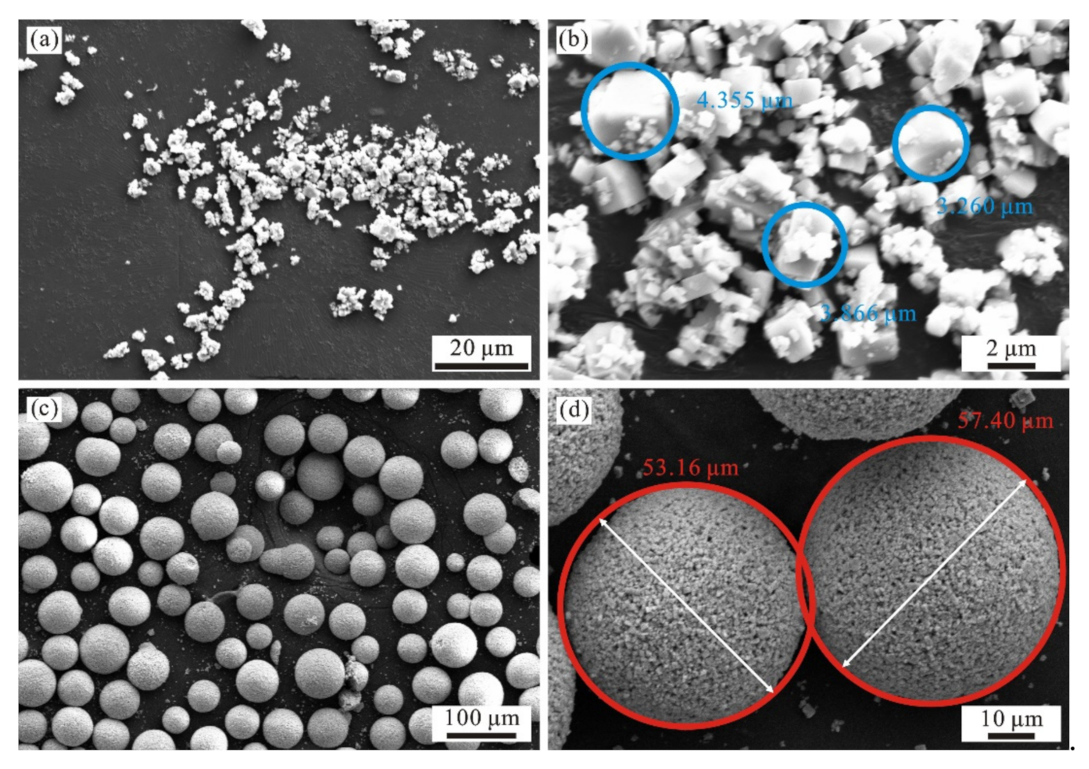
3.1. Microstructures

A cross-sectional view of as-prepared potassium sodium niobate coating is shown in Figure 3. By analyzing the cross-section morphology of coating, it can be found that the thickness of as-prepared coating is about 40 μm. Meanwhile, as seen from Figure 3a, the coating surface has a large number of un-melted particles and pores. This is because that the surface grains have not been secondary heated, which makes a fast cool speed. The tiny powder particles cannot melt and spread completely, so there are many irregular un-melted grains on coating surface. Such un-melted particles on coating surface will increase the leakage current of coating, and leakage current can further improve the residual polarization of coating, and then enhance its electrical properties. However, the internal pores in coating are small, and hence the melting process is appropriate. The main reason is that the powder presents a good spherical shape through granulation. Then, after heating, the powder changes from solid to liquid and spreads on substrate surface. As shown in Figure 3b, the element content rapidly decreases at the combination area between coating and substrate. Moreover, the element transient area is very narrow, but it is not completely break out. Therefore, there is mechanical bonding between as-prepared coating and substrate, and also such bonding is tight.
The three-dimensional morphology, two-dimensional profile curve and roughness of as-prepared coating are shown in Figure 4. As seen in Figure 4a, the altitude difference between the highest point and the lowest point on coating surface is 58.7 μm. The profile curve floats up and down at 10 μm, as shown in Figure 4b the coating arithmetic mean deviation (Ra) of profile roughness is 3.205 μm, and the arithmetic mean deviation (Sa) of regional morphology is 5.891 μm, as shown in Figure 4c The reason for the above values is that some particles on coating surface have not been reheated. As a result, the particles cool and solidify rapidly on coating surface, which is consistent with the results observed in Figure 3a.
X-ray diffraction (XRD) analyses of powder and KNN coating are shown in Figure 5 It can be seen from the figure that the powder and coating are prepared with perovskite structure and tetragonal phase structure, which indicates that thermal spraying does not change the phase structure of KNN. This is because that the spraying time is short and spraying speed is fast. Hence, there is no sufficient time for phase transformation. It can also be seen from Figure 5, the powder has an obvious NaNbO3 characteristic peak at 22.5°. However, such characteristic peak disappeared after thermal spraying and heat treatment. Since high-temperature process has caused Na+ volatilization. In addition, through illustration analyses in Figure 5, the half peak width of coating increases, indicating that coating crystallinity has decreased. The decrease of crystallinity will also reduce the electrical properties of coating. The reason is that supersonic plasma spraying belongs to thermal spraying, and high temperature will cause volatilization of sodium and potassium. Their volatilization will inhibit crystal formation. Although coating crystallinity decreases, the coating still retains good perovskite structure, which can also ensure excellent electrical properties of as-prepared coating.
Figure 6 shows TEM diagram and the corresponding lattice fringes of KNN coating. It can be clearly seen from Figure 6a that as-prepared coating contains a large number of potassium sodium niobate crystals, and the edge position displays obvious amorphous phase. The mean interplanar space calculated from fringe pattern is 0.29 nm. As seen in Figure 6b, the layer contains not only the determined crystalline phase, but also the typical amorphous phase. This is consistent with the decrease of crystallinity observed in Figure 5 The amorphous phase formation is mainly resulted from two aspects. On the one hand, the formation of amorphous phase is due to the inhibition of grain growth under rapid cooling. On the other hand, the volatilization of sodium and potassium during high-temperature spraying can efficiently inhibit grain formation. According to the analysis in Figure 5, although sodium and potassium of coating volatilize due to thermal spraying, the grain formation and growth are inhibited. However, the coating still ensures a good potassium sodium niobate structure, which makes a good structural basis for excellent electrical properties.

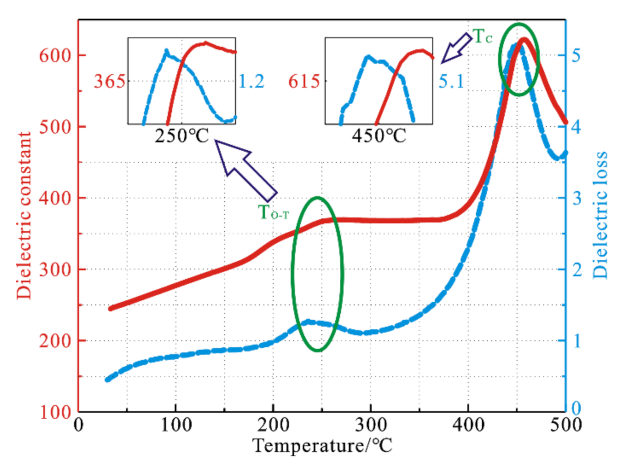
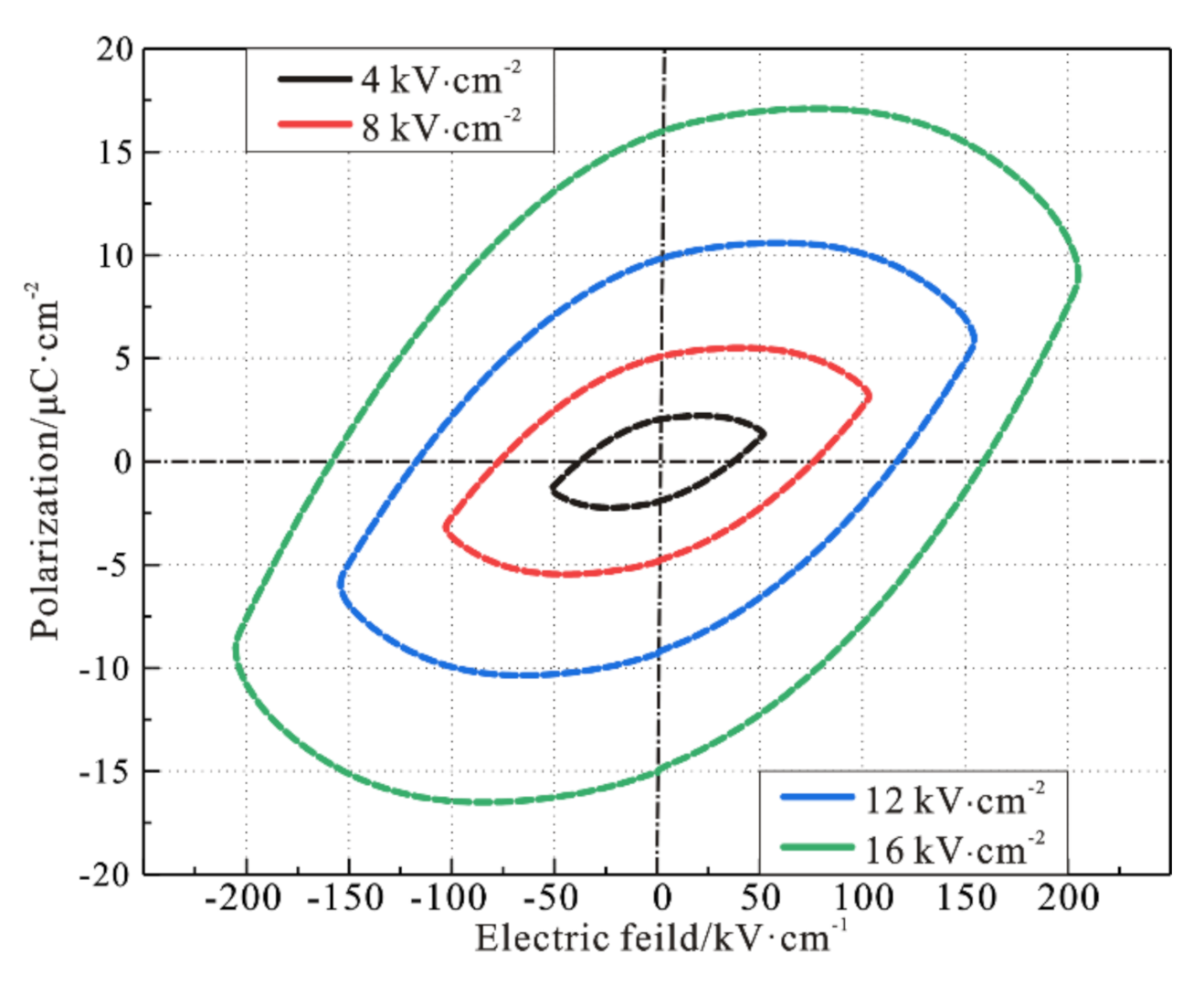
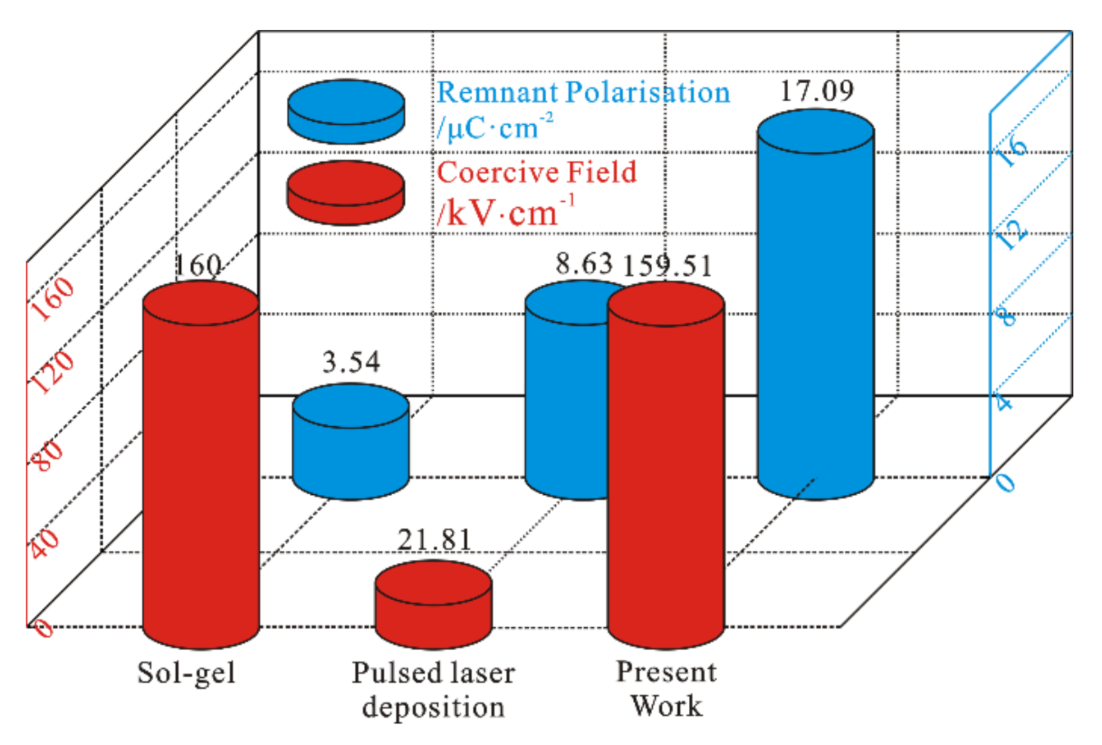
3.2. Electrical Property

Dielectric constant is used to examine the dielectric medium memory charge. Dielectric dissipation is the energy dissipation of piezoelectric ceramic in polarization course. Dielectric loss is the ratio of electric energy consumed by capacitor to stored electric energy, which is related to frequency and temperature.
The dielectric constant of piezoelectric ceramics changes with the temperature, which is determined by internal material structure. With the increase of temperature, the material will change from ferroelectric phase to paraelectric phase. The dielectric constant reflects the difficulty degree of ion displacement under the action of electric field, so it reaches the maximum before ferroelectric phase transition. Furthermore, Curie temperature of material can be estimated by measuring its curve.
Figure 7 shows the variation curve of dielectric constant and dielectric loss of KNN coating from room temperature to 500 °C. As shown in Figure 7, the dielectric constant of KNN coating prepared by supersonic plasma spraying exhibits an increasing trend when temperature rises to 250 °C, but the change is small. The results show that the dielectric properties of KNN ceramics are stable at low temperature, which is conducive to working stability of piezoelectric devices. When temperature increases from 250 °C to 370 °C, dielectric constant tends to be stable. As temperature continues to increase, the dielectric constant raises rapidly. The dielectric coefficient achieves the maximum near 460 °C, and then decreases rapidly. It can be determined that Curie temperature (TC) of KNN coating is about 460 °C. However, the Curie temperature (TC = 420 °C) of KNN prepared by sintering is lower. Furthermore, as seen in Figure 7, the dielectric loss raises with the increase of temperature, and the change trend is similar to dielectric constant in Figure 7, indicating that as-prepared coating has good stability at 250 °C. When temperature rises from 250 °C to 370 °C, the dielectric loss first decreases and then increases, which is due to the coating changes from tripartite phase to tetragonal phase in this temperature range. The dielectric loss increases sharply after 370 °C and reaches the maximum at 550 °C. Mainly due to the high temperature disorder, lattice vibration is violent, and the collision between ions is also violent. Hence, the resultant dielectric loss exhibits a high level.
Figure 8 shows the variation curve of dielectric constant and dielectric loss of KNN coating with frequency. As seen in Figure 8 with the increase of frequency, dielectric constant and dielectric loss show downward trends, and then gradually tend to be stable. In low frequency region (<2 MHz), dielectric constant and dielectric loss greatly change and decrease rapidly. In high frequency region (≥2 MHz), dielectric constant and dielectric loss change little as frequency increases. Furthermore, dielectric constant is stable at about 300 and dielectric loss is stable below 0.05. Therefore, when frequency increases above 2 MHz, dielectric constant and dielectric loss almost show frequency-independent response. Meanwhile, KNN coating has low and stable dielectric loss in high frequency region, which makes it a potential material for microwave application.
Figure 9 shows the relationship between hysteresis loop and electric field of KNN coating at 100 Hz. As seen, when voltage increases to 2 kV, as-prepared coating still maintains a complete hysteresis loop without electric field breakdown. With the increase of electric field, the residual polarization and coercivity field of coating also increase. As the electric field increases from 4 kV·cm−2 to 16 kV·cm−2, the residual coating polarization increases from 2.2 μC·cm−2 to 17.09 μC·cm−2. This is due to the high energy provided by high electric field and high electric energy produces a high electrical drive force on dipole moment. Moreover, with the increase of electric field, the coercive field increases from 37.21 kV·cm−1 to 159.51 kV·cm−1. This is because more domains are reversed under the action of high electric field. Although the coercive field value of coating is larger than that of thin film and bulk ceramics, the residual polarization value of coating is larger.
Figure 10 compares the values of remanant polarization and coercive field obtained by various works. Yan et al. reported the determination of remnant polarization and high coercive field by Sol-gel technique [39]. Similarly, Sharma et al. reported the preparation of KNN coatings with good hysteresis loops by pulsed laser technique [40]. The present work reports a very high remnant polarisation (~17.09 µC·cm−2) along with coercive field (~159.51 kV·cm−1) for as-prepared KNN coatings. Meanwhile, the residual polarization value obtained in our work is much higher than that reported in above literature (3.54 µC·cm−2 and 8.63 µC·cm−2). There are two main reasons for this. On the one hand, the measurement frequency used in reported literature (~1 KHz and 250 Hz) is higher than our work (~100 Hz). For a low frequency, the domain inversion speed can achieve the applied frequency. The higher the frequency, the more the domain cannot keep up with applied frequency. On the other hand, as-prepared coating has leakage current because of pores and un-melted particles. The existence of leakage current will also increase the polarization intensity of coating. Therefore, the residual polarization value of coating in this work is large. In addition to high residual polarization, there is also a large coercive field. Similarly, there is little difference between coercive field value and Reference 39 (160 kV·cm−1), because the frequency is high and the domain is difficult to flip, resulting in a large coercive field value in reported literature. In this work, the reason for high coercive field is that the applied voltage is large, which promotes domain reversal. Compared with the coercivity field reported in Reference 40 (21.81 kV·cm−1), the value is much for our work. The main reason is that as-prepared coating has leakage current because of pores and un-melted particles. The existence of leakage current will also increase the coercive field of coating. Therefore, the coercivity field of KNN coating prepared in this work is large.

4. Conclusions

In this work, potassium sodium niobate ceramic coating has been successfully fabricated by supersonic plasma spraying technology, and the properties of as-prepared coating have also been investigated. The main conclusions are as follows:
(1) There is no obviously transient area between coating and substrate, which exhibits a machine combination. In the spraying process, although the crystallinity of KNN crystal decreases, it still maintains excellent tetragonal phase structure.
(2) Through the analysis of electrical properties, as-prepared KNN coating exhibits superior dielectric and ferroelectric behaviors. The dielectric constant of such coating is stable at about 300 and dielectric loss is steady below 0.05 at high frequency. Meanwhile, the residual polarization of the coating is 17.09 μC·cm−2.
It is found that there are many un-melted particles and large coercivity field on coating surface. Therefore, for the subsequent test in future work, the quality and electrical properties of coating can be improved by optimizing spraying process and adding a transition layer.

Author Contributions

Conceptualization, Y.H. and H.W.; methodology, D.H. and W.G.; investigation, G.H.; writing—original draft preparation, L.Z.; writing—review and editing, Z.X. and X.L. All authors have read and agreed to the published version of the manuscript.

Funding

Financial support from General program of the National Natural Science Foundation of China (Grant No. 51775554); General program of the National Natural Science Foundation of China (Grant No. 52005511) and General program of the National Natural Science Foundation of China (Grant No. 51805539).

Institutional Review Board Statement

Not applicable.

Informed Consent Statement

Not applicable.

Data Availability Statement

The data presented in this study are available on request from the corresponding author.

Conflicts of Interest

The authors declare that they have no known competing financial interest or personal relationships that could have appeared to influence the work reported in this paper.

References

  1. Lee, T.; Lee, J. Setting time and compressive strength prediction model of concrete by nondestructive ultrasonic pulse velocity testing at early age. Constr. Build. Mater. 2020, 252, 119027. [Google Scholar] [CrossRef]
  2. Abramovich, H. The Vibration Correlation Technique—A reliable nondestructive method to predict buckling loads of thin walled structures. Thin-Walled Struct. 2020, 159, 107308. [Google Scholar] [CrossRef]
  3. Huang, Q.D.; Gardoni, P.; Hurlebaus, S. A probabilistic damage detection approach using vibration-based nondestructive testing. Struct. Saf. 2012, 38, 11–21. [Google Scholar] [CrossRef]
  4. Xu, C.G.; Song, W.T.; Pan, Q.X.; Li, H.X.; Liu, S. Nondestructive testing residual stress using ultrasonic critical refracted longitudinal wave. Phys. Proced. 2015, 70, 594–598. [Google Scholar] [CrossRef] [Green Version]
  5. Zhou, Z.Y.; Zheng, Q.Y.; Ding, C.; Yan, J.Y.; Piao, Z.Y. Effect of surface burnishing process with different strain paths on the copper microstructure. J. Manuf. Process. 2021, 71, 653–668. [Google Scholar]
  6. Zhou, Z.Y.; Zheng, Q.Y.; Ding, C.; Yan, J.Y.; Peng, G.J.; Piao, Z.Y. Research on the promotion mechanism of surface burnishing process by two-dimensional ultrasonic vibration. J. Mater. Res. Technol. 2021, 13, 1068–1082. [Google Scholar]
  7. Li, X.W.; Yu, Q.Y.; Chen, X.; Zhang, Q.X. Microstructures and electrochemical behaviors of casting magnesium alloys with enhanced compression strengths and decomposition rates. J. Magnes. Alloy 2021. [Google Scholar] [CrossRef]
  8. Li, X.W.; Liang, J.S.; Shi, T.; Yang, D.N.; Chen, X.C.; Zhang, C.W.; Liu, Z.H.; Liu, D.Z.; Zhang, Q.X. Tribological behaviors of vacuum hot-pressed ceramic composites with enhanced cyclic oxidation and corrosion resistance. Ceram. Int. 2020, 46, 12911–12920. [Google Scholar] [CrossRef]
  9. Hayden, B.E.; Yakovlev, S. Structural, dielectric and ferroelectric properties of (Bi,Na)TiO3-BaTiO3 system studied by high throughput screening. Thin Solid Film. 2016, 603, 108–114. [Google Scholar] [CrossRef] [Green Version]
  10. Clabel, J.L.H.; Awan, I.T.; Rivera, V.A.G.; Nogueira, I.C.; Pereira-da-Silva, M.; Li, M.S.; Ferreira, S.O.; Marega, E. Growth process and grain boundary defects in Er doped BaTiO3 processed by EB-PVD: A study by XRD, FTIR, SEM and AFM. Appl. Surf. Sci. 2019, 493, 982–993. [Google Scholar] [CrossRef]
  11. Reis, D.M.D.; Rzepka, S.; Hiller, K. Reliability testing of integrated low-temperature PVD PZT films. Microelectron. Reliab. 2018, 88, 835–839. [Google Scholar] [CrossRef]
  12. Xie, L.Y.; Huang, X.Y.; Yang, K.; Li, S.T.; Jiang, P.K. “Grafting to” route to PVDF-HFP-GMA/BaTiO3 nanocomposites with high dielectric constant and high thermal conductivity for energy storage and thermal management applications. J. Mater. Chem. 2014, 2, 5244–5251. [Google Scholar] [CrossRef]
  13. Ohno, T.; Fukumitsu, K.; Honda, T.; Sakamoto, A.; Tanaka, S.; Hirai, S.; Matsuda, T.; Sakamoto, N.; Suzuki, H. Piezoelectric properties of a near strain-free lead zirconate titanate thin films deposited on a Si substrate. Mater. Lett. 2019, 239, 71–74. [Google Scholar] [CrossRef]
  14. Li, X.M.; Wu, X.Q.; Ren, W.; Shi, P.; Ye, Z.G. Preparation and characterization of sodium potassium niobate-silver niobate lead-free films by chemical solution deposition. Ceram. Int. 2015, 41, 228–233. [Google Scholar] [CrossRef]
  15. Raeder, T.M.; Bakken, K.; Glaum, J.; Einarsrud, M.A.; Grande, T. Enhanced in-plane ferroelectricity in BaTiO3 thin films fabricated by aqueous chemical solution deposition. AIP Adv. 2018, 8, 105228. [Google Scholar] [CrossRef] [Green Version]
  16. Uchida, H.; Oi, T.; Noguchi, K.; Moki, S.; Kim, J.W.; Shima, H.; Nishida, K.; Kiguchi, T.; Akama, A.; Konno, T.J.; et al. Orientation control of barium titanate films using metal oxide nanosheet layer. Jpn. J. Appl. Phys. 2016, 55, 10TA15. [Google Scholar] [CrossRef]
  17. Bruncková, H.; Medvecký, Ľ.; Hvizdoš, P. Effect of substrate on microstructure and mechanical properties of sol–gel prepared (K, Na)NbO3 thin films. Mater. Sci. Eng. 2013, 178, 254–262. [Google Scholar] [CrossRef]
  18. Tachafine, A.; Fasquelle, D.; Desfeux, R.; Ferri, A.; Da Costa, A.; Carru, J.C.; Outzourhit, A. Doping effect on nanoscopic and macroscopic electrical properties of Barium Zirconate Titanate thin films. Spectrosc Lett. 2021, 54, 507–519. [Google Scholar] [CrossRef]
  19. Kawamura, G.; Ohara, K.; Tan, W.K.; Goto, T.; Nakamura, Y.; Inoue, M.; Muto, H.; Yamaguchi, K.; Boccaccini, A.R.; Matsuda, A. Multiferroic nanocomposite fabrication via liquid phase using anodic alumina template. Sci. Technol. Adv. Mat. 2018, 19, 535–542. [Google Scholar] [CrossRef] [PubMed] [Green Version]
  20. Liu, Y.M.; Lam, K.H.; Shung, K.K.; Li, J.Y. Enhanced piezoelectric performance of composite sol–gel thick films evaluated using piezoresponse force microscopy. J. Appl. Phys. 2014, 13, 187205. [Google Scholar] [CrossRef] [Green Version]
  21. Guo, K.; Mirshekarloo, M.S.; Lin, M.; Yao, K.; Chen, S.T.; Tay, F.E.H. Microstructure and piezoelectric properties of thermal sprayed Bi0.5(Na0.70K0.20Li0.10)0.5TiO3 ceramic coatings. Ceram. Int. 2019, 45, 3570–3573. [Google Scholar] [CrossRef]
  22. Xing, Z.G.; Wang, H.D.; Zhu, L.N.; Zhou, X.Y.; Huang, Y.F. Properties of the BaTiO3 coating prepared by supersonic plasma spraying. J. Alloy Compd. 2014, 582, 246–252. [Google Scholar] [CrossRef]
  23. Wang, Y.W.; Sun, X.W.; Wang, L.; Yang, Y.; Ren, X.X.; Ma, Y.D.; Cui, Y.H.; Sun, W.W.; Wang, X.Y.; Dong, Y.C. Microstructure and properties of CrB2-Cr3C2 composite coatings prepared by plasma spraying. Surf. Coat. Technol. 2021, 425, 127693. [Google Scholar] [CrossRef]
  24. Yang, J.J.; Jia, J.H.; Li, X.; Lu, C.; Feng, X.C. Synergistic lubrication of Ag and Ag2MoO4 nanoparticles anchored in plasma-sprayed YSZ coatings: Remarkably-durable lubricating performance at 800 °C. Tribol. Int. 2021, 153, 106670. [Google Scholar] [CrossRef]
  25. Chen, S.Y.; Wang, H.D.; Xu, B.S.; Kang, J.J. Investigation on the bonding behavior of the interface within the supersonic plasma sprayed coating system based on the fractal theory. Acta Phys. Sin. 2014, 63, 156801. [Google Scholar] [CrossRef]
  26. Haessler, W.; Thielsch, R.; Mattern, N. Structure and Electrical Properties of PZT Thick Films Produced by Plasma Spraying. Mater. Lett. 1995, 24, 387–391. [Google Scholar] [CrossRef]
  27. Zhang, J.; Zhang, Y.S.; Yan, Z.M.; Wang, A.J.; Jiang, P.; Zhong, M. Fabrication and performance of PNN-PZT piezoelectric ceramics obtained by low-temperature sintering. Sci. Eng. Compos. Mater. 2020, 27, 359–365. [Google Scholar] [CrossRef]
  28. Bian, K.; Gu, Q.L.; Zhu, K.J.; Zhu, R.Q.; Wang, J.; Liu, J.S.; Qiu, J.H. Improved sintering activity and piezoelectric properties of PZT ceramics from hydrothermally synthesized powders with Pb excess. J. Mater. Sci. Mater. Electron. 2016, 27, 8573–8579. [Google Scholar] [CrossRef]
  29. Wang, J.; Xing, Z.G.; Lv, Z.L.; Ding, K.N.; Wang, H.D. First-principle study of the properties in BaTiO3 and the electronic structure of H2O adsorption on BaTiO3. Int. J. Quantum Chem. 2021, 121, e26576. [Google Scholar] [CrossRef]
  30. Tenne, D.A.; Turner, P.; Schmidt, J.D.; Biegalski, M.; Li, Y.L.; Chen, L.Q.; Soukiassian, A.; Trolier-McKinstry, S.; Schlom, D.G.; Xi, X.X.; et al. Ferroelectricity in ultrathin BaTiO3 films: Probing the size effect by ultraviolet Raman spectroscopy. Phys. Rev. Lett. 2009, 103, 177601. [Google Scholar] [CrossRef] [Green Version]
  31. Pop-Ghe, P.; Wolff, N.; Rubab, A.; Kienle, L.; Quandt, E. Tailoring growth modes by excess alkali addition in magnetron sputtered potassium sodium niobate thin films. Mater Today Commun. 2022, 27, 102221. [Google Scholar] [CrossRef]
  32. Sharma, S.; Gupta, R.; Kumar, A.; Gupta, V.; Tomar, M. Investigation of optical non-linearity of lead-free ferroelectric potassium sodium niobate (K0.35Na0.65NbO3) thin films via two-wave mixing phenomenon. Opt. Laser Technol. 2021, 141, 107148. [Google Scholar] [CrossRef]
  33. Burns, S.R.; Dolgos, M.R. Sizing up (K1-xNax)NbO3 films: A review of synthesis routes, properties & applications. New J. Chem. 2021, 45, 7408–7436. [Google Scholar]
  34. Akmal, M.H.M.; Warikh, A.R.M. Electrical behaviour of yttrium-doped potassium sodium niobate thin film for piezoelectric energy harvester applications. J. Aust. Ceram. Soc. 2021, 57, 589–596. [Google Scholar] [CrossRef]
  35. Chen, S.T.; Tan, C.K.I.; Yao, K. Potassium–sodium niobate-based lead-free piezoelectric ceramic coatings by thermal spray process. J. Am. Ceram. Soc. 2016, 99, 3293–3299. [Google Scholar] [CrossRef]
  36. Chen, S.T.; Tan, C.K.I.; Tan, S.Y.; Guo, S.F.; Zhang, L.; Yao, K. Potassium sodium niobate (KNN)-based lead-free piezoelectric ceramic coatings on steel structure by thermal spray method. J. Am. Ceram. Soc. 2018, 101, 5524–5533. [Google Scholar] [CrossRef]
  37. Guo, S.F.; Zhang, L.; Chen, S.T.; Tan, C.K.I.; Yao, K. Ultrasonic transducers from thermal sprayed lead-free piezoelectric ceramic coatings for in-situ structural monitoring for pipelines. Smart Mater. Struct. 2019, 28, 075031. [Google Scholar] [CrossRef]
  38. Li, G.L.; Gu, L.S.; Wang, H.D.; Xing, Z.G.; Zhu, L.N. Microstructures and Dielectric Properties of PZT Coatings Prepared by Supersonic Plasma Spraying. J. Therm. Spray Technol. 2014, 23, 525–529. [Google Scholar] [CrossRef]
  39. Yan, X.; Ren, W.; Wu, X.Q.; Shi, P.; Yao, X. Lead-free(K,Na)NbO3 ferroelectric thin films: Preparation, structure and electrical properties. J. Alloy Compd. 2010, 508, 129–132. [Google Scholar] [CrossRef]
  40. Sharma, S.; Kumar, A.; Gupta, V.; Tomar, M. Dielectric and ferroelectric studies of KNN thin film grown by pulsed laser deposition technique. Vacuum 2019, 160, 233–237. [Google Scholar] [CrossRef]
Figure 1. SEM of powder: (a,b) the powder before granulation; (c,d) the powder after granulation.
Actuators 11 00028 g001
Figure 2. Heat treatment process.
Actuators 11 00028 g002
Figure 3. Cross-section morphology of as-prepared KNN coating: (a) SEM image; (b) EDS spectrum.
Actuators 11 00028 g003
Figure 4. The three-dimensional morphologies of as-prepared KNN coating: (a) Three-dimensional morphology; (b) Two-dimensional profile curve; (c) Coating roughness.
Actuators 11 00028 g004
Figure 5. XRD patterns of powder and coating.
Actuators 11 00028 g005
Figure 6. TEM diagram and corresponding lattice fringes of KNN coating. (a) TEM diagram, (b) Corresponding lattice fringes.
Actuators 11 00028 g006
Figure 7. Variation curve of dielectric constant and dielectric loss of KNN coating with temperature.
Actuators 11 00028 g007
Figure 8. Variation curve of dielectric constant and dielectric loss of KNN coating with frequency.
Actuators 11 00028 g008
Figure 9. Relationship between hysteresis loop and electric field of KNN coating at 100 Hz.
Actuators 11 00028 g009
Figure 10. Residual polarization and coercive field of KNN coating prepared by different processes.
Actuators 11 00028 g010
Table 1. Spraying parameters.
Spraying Voltage/VSpraying Current/ASpraying Distance/mmPowder Feeding Rate/
g·min−1
Ar Gas Flow/
L·min−1
H2 Gas Flow/
L·min−1
4001201002512010
Publisher’s Note: MDPI stays neutral with regard to jurisdictional claims in published maps and institutional affiliations.

