Article

Dual Synthetic Jets Actuator and Its Applications—Part III: Impingement Flow Field and Cooling Characteristics of Vectoring Dual Synthetic Jets

1
College of Aerospace Science and Engineering, National University of Defense Technology, Changsha 410073, China
2
School of Energy and Power Engineering, Xi’an Jiaotong University, Xi’an 710049, China
*
Authors to whom correspondence should be addressed.
Actuators 2022, 11(12), 376; https://doi.org/10.3390/act11120376
Submission received: 7 November 2022 / Revised: 8 December 2022 / Accepted: 10 December 2022 / Published: 15 December 2022
(This article belongs to the Special Issue Active Flow Control: Recent Advances in Fundamentals and Applications)

Abstract

:
In order to understand the impingement flow field and cooling characteristics of vectoring dual synthetic jets (DSJ), an experimental investigation was performed to analyze the parameter effects. With the variation of the slot location, the vectoring angle of DSJ can be adjusted from 34.5° toward the left to 29.5° toward the right. The vectoring function can greatly extend the length of impingement region. There are three local peaks both for the local cooling performance (Nu) and the whole cooling performance (Nuavg). Although the peak Nu at a certain location of the slider is higher than that at the center, the corresponding Nuavg is lower. As for different driving frequencies, the vectoring angle reaches its minimum of 9.7° at 350 Hz, but the Nu is obviously improved. There is one local peak of Nuavg values at 350 Hz rather than three local peaks at 250 Hz and 450 Hz. The slot locations where the Nuavg of 250 Hz and 450 Hz reach maximum are different. With the increase in driving voltage from ±100 V to ±200 V, the vectoring angle drops from 46.9° to 22.2°, but both Nu and Nuavg are improved. The maximum Nuavg of each driving voltage occurs at the center location of the slider. The choking effect and the cross flow have dominated the vectoring angle and the cooling performance of impingement DSJ. Vectoring DSJ will give impetus to the thermal management of large-area electric devices in spaced-constrained cooling and removing dynamic hotspots.

1. Introduction

Due to the unique capability of additional momentum injecting into ambient fluid without complex plumbing, synthetic jet technology shows a significant potential for active flow control. Synthetic jets have been engaged in applications of aerodynamic force control [1,2,3,4,5], flow separation control [6,7,8,9], mixing enhancement [10,11,12], jet vectoring control [13,14,15], heat transfer enhancement [16,17,18,19], etc. With the development of integrated electrical systems in miniaturization and high power, the cooling problem becomes a greater challenge. Traditional cooling techniques such as fans and heat pipes cannot satisfy the demands of compact cooling systems. Thus, there is an urgent need to seek a simple and high-efficiency cooling method.
Impinging jets have been widely used in electronic cooling due to the high heat transfer coefficient [20]. However, there are some obvious disadvantages for impinging jets, such as high energy consumptions and needs of external fluid plumbing. Thus, the development of an impinging synthetic jet which needs no fluid supply system has drawn researchers’ attention. Because of the interactions of coherent structures with thermal boundaries [21,22], the impingement cooling performance of a synthetic jet is much better than a continuous jet [23]. Luis and Alfonso [24] revealed the mechanism of the heat transfer enhancement of an impinging synthetic jet by analyzing the vortex dynamics. They discovered that a secondary vortex with an opposite circulation was generated after the vortex pair arrived at the heated wall. Greco et al. [25] investigated the combined effect of impingement distance and stroke length on the cooling performance of an impinging synthetic jet. Both inner and outer ring-shaped regions occurred at a short impingement distance under the highest dimensionless stroke length. As the impingement spacing increased, the outer ring-shaped regions disappeared owing to the weakening of secondary vortex rings. Qiu et al. [26] analyzed the effect of the interactions between a circular synthetic jet and a cross flow in a microchannel on the heat transfer process. They pointed out that the heat transfer enhancement could be divided into two parts of an impinging region and an entraining region. Lyu et al. [27] investigated the heat transfer characteristics of a single synthetic jet with two planar-lobed orifices impinging on flat and concave surfaces. It was demonstrated that the N = 6 petal-shaped orifice was a most promising orifice configuration. For the baseline round orifice, the spatially-averaged Nu was reduced up to 25% on the concave surface with respect to the flat surface. Lau et al. [28] analyzed the effects of nanoparticle types and volume concentrations on the heat transfer in a three-dimensional microchannel with a synthetic jet based on a Eulerian approach. With the increase in the volume concentration, the viscosity became higher, resulting in a poorer cooling performance. The overall cooling performance of Al2O3-water nanofluid was the best at the volume concentration of 5%. Wang et al. [29] investigated the flow characteristics and unsteady heat transfer of noncircular synthetic jets impinging on a heated plate. Compared with the circular orifice, the jet penetration from the square orifice into the wall shear layer was deeper, and the maximum stagnation cooling coefficient increased 42%. The axis-switching phenomenon of elliptic and rectangular orifices enhanced the near-wall mixing and the turbulent kinetic energy. The heat transfer was improved compared with the circular orifice. The flow and thermal behavior of impingement synthetic jet driven by sinusoidal and square signals were analyzed by Singh et al. [30]. It was found that the cooling performance in the stagnation region with square signal is 18.94% higher than that with sinusoidal signal, but the averaged Nusselt number with the sinusoidal signal is 20.86% higher.
As above mentioned, the impingement cooling based on a traditional synthetic jet cannot vary the jet direction, and thus the cooling area is certain and limited. It is not applicable to the large-area cooling and the removal of dynamic hotspots. Considering this, vectoring dual synthetic jets (DSJ) was developed realized by controlling the movement of a slider based on a synthetic jet [31,32,33,34]. It has been found that DSJ has exhibited an excellent performance in impingement cooling and spray cooling [35,36,37,38]. Moreover, vectoring DSJ has been proven to be a useful cooling technology in space-constrained and large-area electronic cooling [39].
The vectoring function and the doubled energy utilization efficiency of vectoring DSJ make it potentially useful for cooling applications. The aim of the present work is to investigate the effects of slider location, driving voltage and driving frequency on the impingement flow field and cooling characteristics of vectoring DSJ. A compact thermal management strategy is provided for space-restricted electronic cooling based on a vectoring DSJ.

2. Experimental Device and Methods

2.1. Experimental Device

The experiment set up, as sketched in Figure 1, included a vectoring DSJ actuator, an impinged plate, a particle image velocimetry (PIV) system, and an infrared camera. The vectoring DSJ actuator driven by a sine signal was installed under the plate with a constant distance of 40 mm. The configurations of two slots are shown in Figure 1a, and each width of two slots could be adjusted by changing the slider location through a step motor (seeing Figure 1b). A stainless-steel foil (196 mm × 100 mm × 0.08 mm) was selected as the impinged plate.
A 2D PIV system of MicroVec Corp. was used to measure the impingement flow field of vectoring DSJ. A sheet light with a thickness of 1 mm was generated from a twin-cavity Nd: YAG laser with a separation of 12 μs. The output energy of each laser pulse was about 200 mJ with a duration of 7 ns. The impingement model of vectoring DSJ was covered in a Plexiglas® container. The xoz plane was brightened by a laser sheet of 1 mm thickness at a frequency of 10 Hz. The particle images with a resolution of 0.035 mm/pixel were recorded by a charge-coupled device (CCD) through an optical filter. The cross-frame time was set according to the DSJ velocity. Phase-locked and phase-shifting technologies were used to capture the images at 16 equal-divided phases of the DSJ period. A velocity field has been processed using the MicroVec 3.0 software package based on a two-frame cross-correlation algorithm with an interrogation window of 32 × 16 pixels and 50% overlap. A phase-averaged flow field was calculated according to 24 pairs of velocity fields at each phase point. Then the period-averaged flow field of impingement DSJ was achieved by averaging the 16 phase-averaged flow fields.
A FLIR infrared camera was installed above to measure the temperature distribution on the top surface of the impinged plate. The measurement range was from 5 °C to 2500 °C with an accuracy of ±1 °C. The impinged plate was steadily and uniformly heated by a direct-current source. Since the maximum Biot number was 0.0013, which was much less than the critical value of 0.1 along the thickness direction, the temperature of the top surface and impinged surface at the same location could be deemed to be consistent. To improve the radiation feature and the measurement accuracy, a thin and uniform layer of a black matted paint with an emissivity of 0.95 was painted on both sides of the plate. When the plate reached its thermal equilibrium, fifty thermal images were recorded with a sampling frequency of 20 Hz. The steady-status temperature distribution was obtained by averaging the fifty thermal images.

2.2. Vectoring Evaluation Method of Impinging DSJ

In order to explicitly quantify the vectoring angle of DSJ, an evaluation method was proposed based on the potential core. Firstly, a potential core was selected to cover the vast bulk of jet momentum in an evaluated flow field. Secondly, we considered a line and projected the velocity vectors in the potential core onto the line. An objective function was defined as the sum of the projection values of the velocity vectors in the potential core. Thus, the objective function could be deemed as the impinging strength of the jet momentum in the potential core along the line. Finally, the maximum of the objective function could be achieved for a specific projected line. The inclination angle of the specific line was prescribed as the vectoring angle of flow field. The detailed algorithm is explained as follows.
In this paper, the critical velocity Vc is defined as half of the maximum velocity magnitude in the period-averaged flow field of the vectoring DSJ. The region with velocity magnitude beyond the critical velocity is regarded as the potential core.
V c = V max 2 = max ( | V i | ) 2 = max ( u i 2 + w i 2 ) 2
where Vi denotes the velocity vectors with components of ui and wi along x-axis and z-axis, respectively.
According to the definition above, the objective function So is expressed as
S o = i = 1 n ( V i · e θ ) | | V i | V c
where eθ is the unit vector along an assuming line with an inclination angle θ with respect to z-axis, depicted as
e θ = ( tan θ 1 + tan 2 θ ,   1 1 + tan 2 θ )
Then, the objective function can be written as
S o = i = 1 n ( V i · e θ ) | | V i | V c = ( i = 1 n u i tan θ 1 + tan 2 θ + i = 1 n w i 1 + tan 2 θ ) | | V i | V c = tan θ i = 1 n u i + i = 1 n w i 1 + tan 2 θ | | V i | V c
It can be concluded that there must be a specific angle θ0, at which the objective function reaches its maximum. The mathematical relation is given by
( S o ) max = lim θ θ 0 S o
As mentioned above, θ0 represents the direction of the jet momentum in the potential core, and also the vectoring angle of flow field.

2.3. Cooling Performance Evaluation Method of Impinging DSJ

The local cooling performance of impingement DSJ, namely the Nusselt number (Nu), is evaluated by
N u = h d e λ
where λ is the thermal conductivity of air at the average temperature of the impinged surface. The slider width of 5 mm is chosen as the characteristic length de. h is the local heat transfer coefficient of impingement DSJ expressed as
h = q n e t T s T j
where qnet is the net heat flux removed by impingement jet, Ts and Tj are the local temperature of impingement surface and jet temperature, respectively.
The net heat flux is estimated as follows
q n e t = Q e l e Q l o s s A
where Qele is the heating power, Qloss is the total heat loss, A is the effective heating area of impinged surface.
The area-averaged Nusselt number (Nuavg) of the whole impingement surface is calculated by:
N u a v g = Ω N u d x d y A Ω
where AΩ is the image area recorded by the infrared camera.
In the experiments, the heating power is kept a constant of 40 W with a measurement error less than 1.4%. The total loss heat resulted from the radiation and the lateral is estimated to be within 6.4% of the heating power. The uncertainty of Nu is less than 8% through the evaluation method [40].

3. Results and Discussion

3.1. Effect of Slider Location

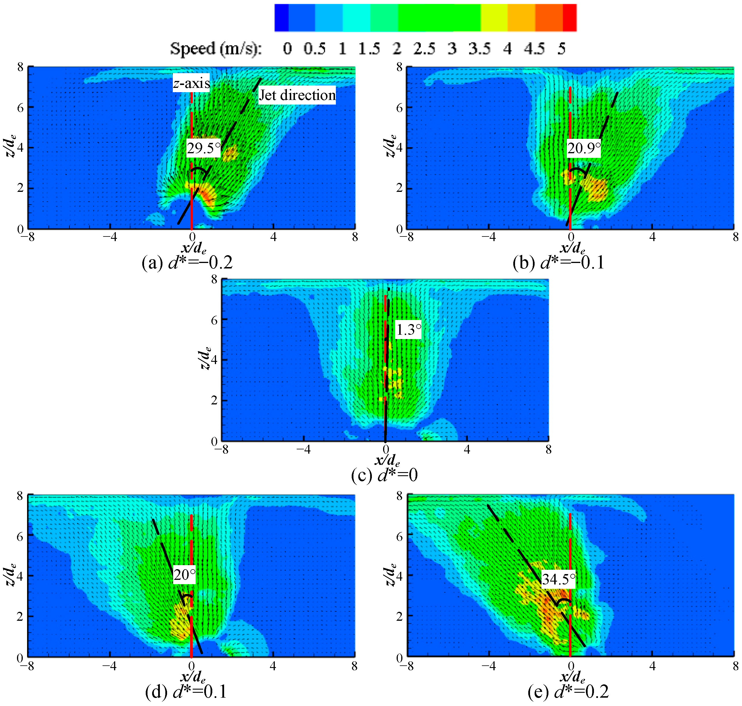
The slider location determines the area ratio of two slots which influences the momentum ratio of two synthetic jets and the strength of the low-pressure region. Thus, different momentums of two synthetic jets result in the deflection of DSJ. Comparing to a traditional synthetic jet, vectoring DSJ can greatly extend the impingement area. The PIV results with different dimensionless slider location d*, defined as d/de, are exhibited in Figure 2. The driving voltage and driving frequency are set to ±150 V and 450 Hz, respectively.
As demonstrated in Figure 2, the DSJ deflects toward the side of the slot with a greater cross section. The reason is that the jet momentum from a smaller width slot is higher, which can be deemed as a primary jet. Conversely, the other jet with a lower momentum is regarded as a disturbing jet. As the primary jet issues from the slot, the other jet is in the suction phase. A low-pressure region is generated near the slot, which causes the primary jet deflects. As the disturbing jet is formed in the blowing phase, the primary jet has moved downstream. The entrainment of vortex structures in the disturbing jet accelerates the deflection of the downstream primary jet. So, the DSJ deflects toward the slot with a larger cross section. With d* varying from −0.2 to 0.2, the vectoring DSJ can deflect from 34.5° toward the left to 29.5° toward the right. Since the momentums of two synthetic jets are equal at d* = 0, there is no deflection. The vectoring angle of 1.3° at d* = 0 (in Figure 2c) may be attributed to the asymmetry of two slots resulting from machining errors. It is observed that the stagnation region length is about 8de (from −4de to 4de) for the normal DSJ (seeing Figure 2c), while for the vectoring DSJ it increases to 15de (from more than −8de in Figure 2a to 7de in Figure 2e). Additionally, the jet velocity becomes a little higher at an off-center slider location. It has been proved that the heat transfer coefficient decreases with the increase in the inclination angle of synthetic jet, and reaches the maximum for the normal impingement [41]. Considering the vectoring characteristic, the vectoring DSJ can be obliquely installed to make its impingement normal. This feature will be greatly useful in spaced-constrained cooling applications.
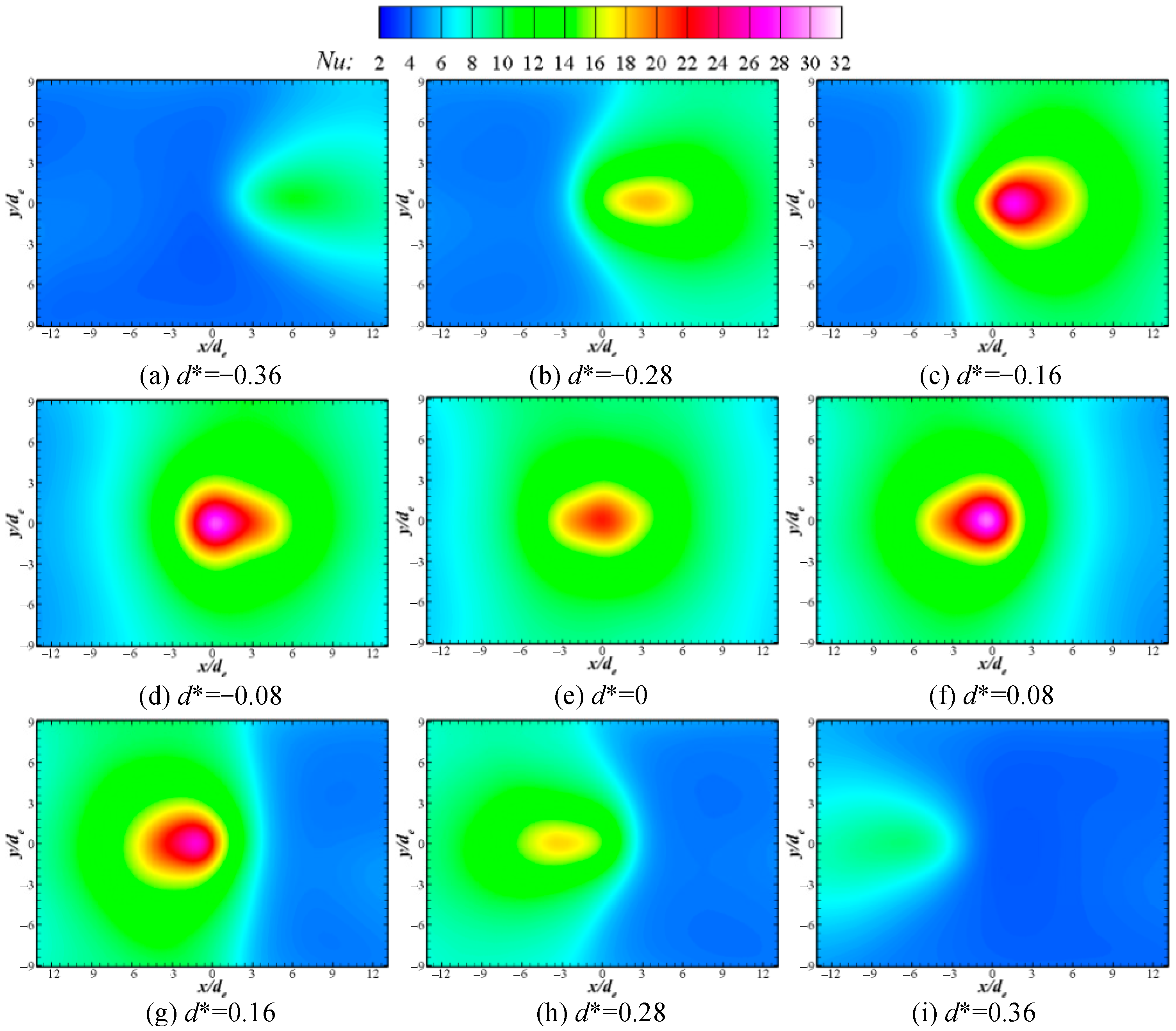
Figure 3 shows the Nu distributions on the impinged surface at different slider locations. The driving voltage and the driving frequency are kept at ±150 V and 500 Hz, respectively. It is indicated that the Nu distribution at d* = 0 is self-symmetrical and two Nu distributions at a same |d*| are symmetrical about the line x/de = 0. The high Nu area gradually moves away from the center with the increase in |d*|. The reason is that with the increase in |d*|, the vectoring angle of DSJ becomes larger which causes the stagnation region moving away from the center.
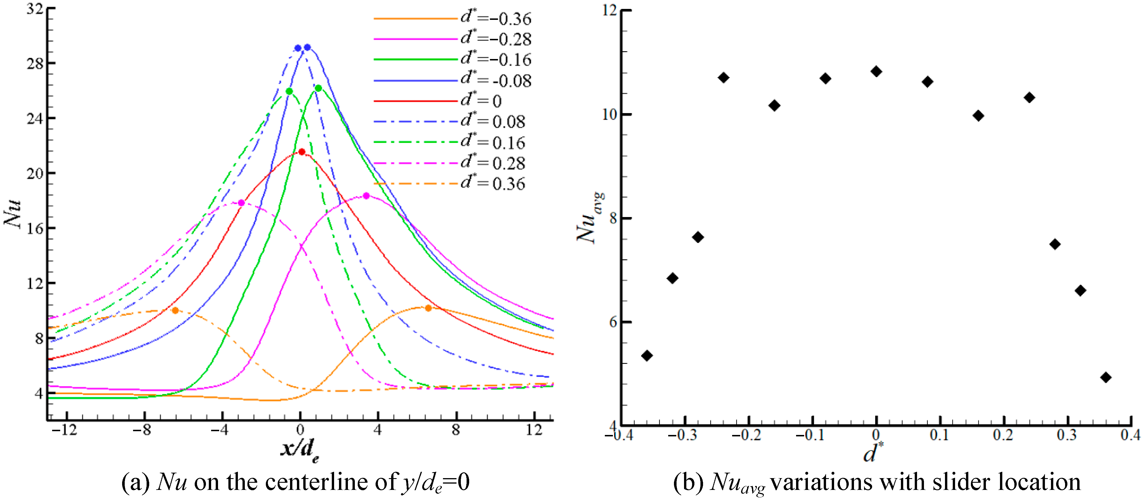
Figure 4a draws the Nu on the centerline y/de = 0 along the x-axis. The solid dot represents the peak Nu on the curves. It can be seen that the curves at the same |d*| are symmetrical with the line x/de = 0. With the increase in |d*|, the curves and peak point of Nu gradually move away from the center, which is consistent with the variation trend of the vectoring angle (shown in Figure 2). The peak Nu reaches its maximum at |d*| = 0.08 rather than at the center location. The reason is that the DSJ velocity increases with the increase in |d*|, which improves the local cooling performance. As |d*| continues to increase, the thickness of the viscous layer in the slot neck gradually grows and eventually fills the entire neck. As a result, the choking effect occurs in the slot neck and the DSJ velocity reduces. Moreover, the vectoring angle increases with the increase in |d*| (shown in Figure 2) and the impingement DSJ will gradually transform to a cross flow, resulting in the weakness of the cooling performance. There are three local peaks of Nuavg at d* = 0 and ±0.28 (shown in Figure 4b). The reason is that at the beginning of |d*| increase, the DSJ velocity increases, which improves the whole cooling performance. As |d*| continues to increase, the choking effect impairs the DSJ velocity, and meanwhile the increase in vectoring angle enhances the cross-flow effect of the DSJ. Thus, the whole cooling performance reduces rapidly. Although the maximum values of Nu at d* = ±0.08 and ±0.16 are larger than that at d* = 0 (shown in Figure 4a), the values of Nuavg are smaller (shown in Figure 4b). Since the DSJ velocity d* = ±0.08 and ±0.16 are higher than that at d* = 0 owing to the smaller cross sections, and the local cooling performance. However, the vectoring angles at d* = ±0.08 and ±0.16 enhance the cross-flow effect and reduce the impingement stagnation region of the DSJ, which causes the decrease in overall cooling performance.

3.2. Effect of Driving Frequency

Previous work [42] has shown that the frequency response of a piezoelectric-driven synthetic jet actuator is consistent with that of a damped fourth order system governed by two key resonance frequencies—the natural frequency of the vibrating diaphragm and the Helmholtz resonance frequency. There are two local peaks of jet velocity and energy efficiency at the two resonance frequencies. In this section, experiments on the effect of driving frequency are carried out at a constant driving voltage of ±150 V and d* = 0.2. The PIV results are illustrated in Figure 5.
It is observed from Figure 5 that the vectoring angle shows a non-monotonic variation trend with the increase in driving frequency. The minimum vectoring angle is 9.7° at the driving frequency of 350 Hz. The natural frequency of vibrating diaphragm is about 360 Hz. Since the amplitude of the vibrating diaphragm will increases significantly near the natural frequency, the DSJ velocity at 350 Hz is much higher than that at the other two frequencies. A higher DSJ velocity requires a greater force to deflect. Thus, the vectoring angle and the impingement stagnation region become small. To prevent electrical and mechanical failure of the vibrating diaphragm, the driving frequency should not be set at the resonant frequency. The driving frequency should be chosen by balancing the cooling performance and the service life of the DSJ actuator.
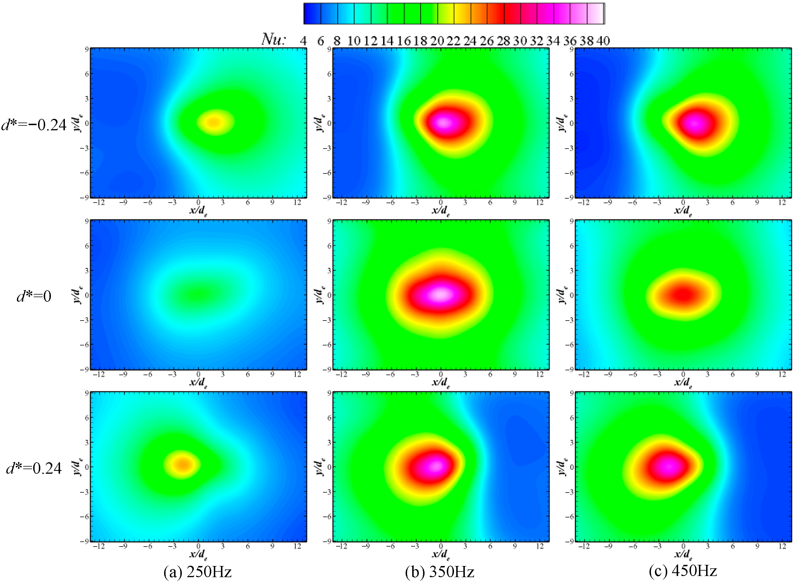
Nu contours on the impinged surface at different driving frequencies and slider locations are displayed in Figure 6. It can be seen that the peak Nu and the high Nu area of 350 Hz are obviously larger than those of 250 Hz and 450 Hz for each slider location. It is attributed to the frequency of 350 Hz close to the resonant frequency where the jet velocity is very higher (shown in Figure 5). As a result, the local heat transfer coefficients are higher than those of other two frequencies which are far away from the resonant frequency. For the driving frequency of 350 Hz, the peak Nu at d* = 0 is greater than those at d* = ±0.24. The tendencies are contrary at driving frequency of 250 Hz and 450 Hz. The reason is that the DSJ velocity of 350 Hz is high enough at d* = 0, and the choking effect occurs in the narrow slot neck during the slider moving away from the center. It means although the cross section of the slot becomes smaller, the jet velocity may decrease, such as the slider locations of d* = ±0.24. For the driving frequency of 250 Hz and 450 Hz, the DSJ velocities are low at d* = 0 and increase with the decrease in the slot cross section at d* = ±0.24. A higher DSJ velocity produces a better local cooling performance and a higher local Nu.
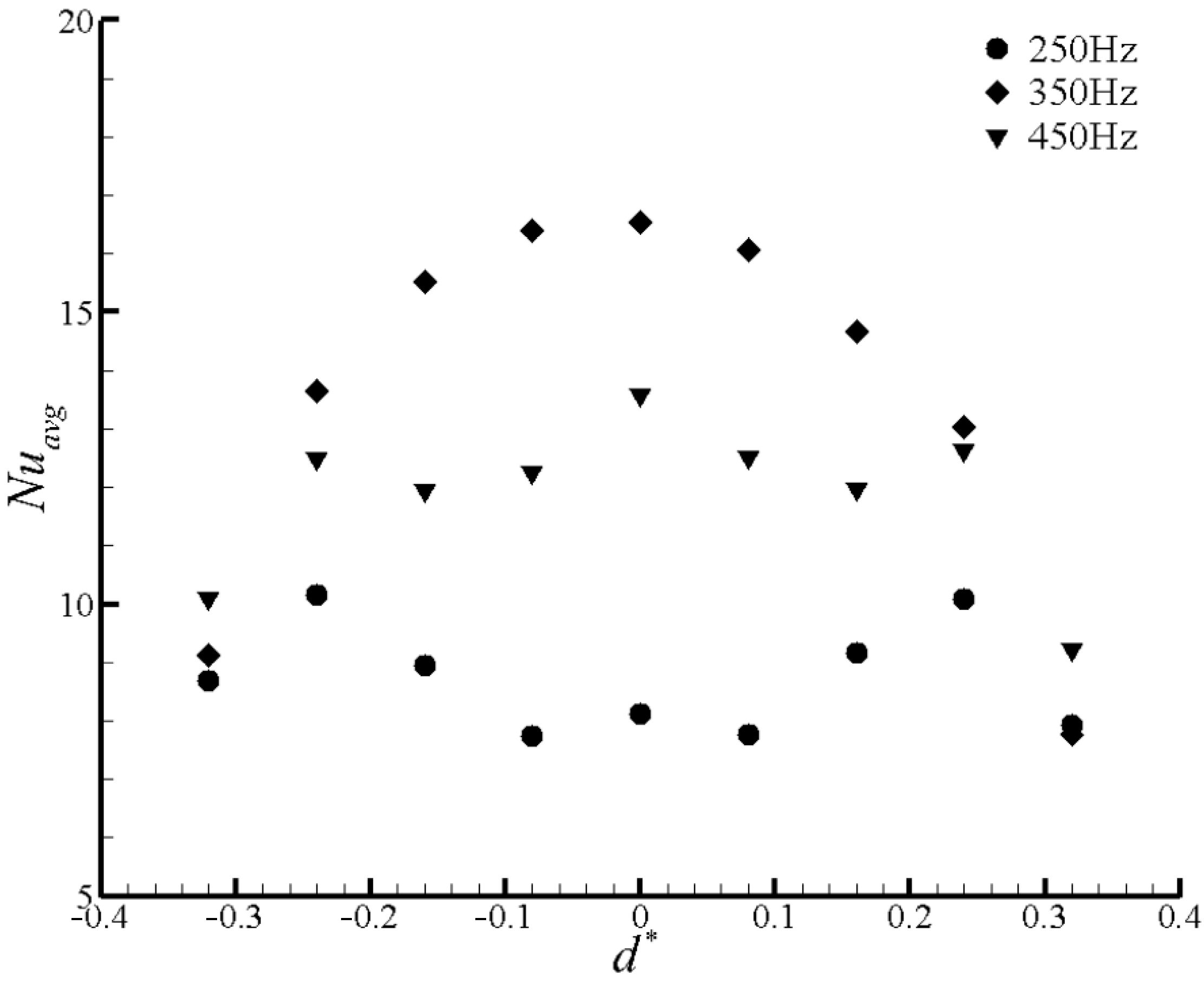
Nuavg with different drive frequencies and slider locations are shown in Figure 7. Results in Figure 7 indicate that there are three local peaks at d* = 0 and d* = ±0.24 both for 250 Hz and 450 Hz, which is similar to Figure 4b. The distinction is that the maximum Nuavg of 450 Hz occurs at d* = 0 rather than that of 250 Hz at d* = ±0.24. The reason is that at d* = 0 the DSJ velocity of 250 Hz is smaller than that of 450 Hz and increases more obviously at d* = ±0.24. In addition, the impingement area is larger at d* = ±0.24 than that at d* = 0. As a result, the cooling performance at d* = ±0.24 is better than that at d* = 0. There is only one local peak with the drive frequency of 350 Hz, which is different from the drive frequency of 250 Hz and 450 Hz. It is attributed to that the DSJ velocity at 350 Hz becomes small owing to the choking effect in the slot neck when the slider moves away from the center. The decrease in DSJ velocity is more remarkable than the increase in impingement stagnation region, and thus the whole cooling performance gradually becomes weak. For the driving frequency of 250 Hz, although the DSJ velocity at d* = ±0.08 is a little higher than that at d* = 0, the cross-flow effect is more obvious due to the vectoring deflection. Overall, the whole cooling performance decreases a bit. As the slider location moves to d* = ±0.24, the increase in the DSJ velocity is more remarkable than the enhancement of the cross-flow effect. Thus, the whole cooling performance gradually improves. As |d*| continues to increase, the choking effect occurs and impairs the DSJ velocity. The whole cooling performance reduces. The explanation for the variation trend of Nuavg at 350 Hz is similar to the above mentioned about 250 Hz. The differences are that the maximum Nuavg of 450 Hz occurs at d* = 0 rather than that of 250 Hz at d* = ±0.24. The reason is that the DSJ velocity of 250 Hz can be obviously enhanced with the increase in |d*|, which improves the whole cooling performance.

3.3. Effect of Driving Voltage

The driving voltage influences the input power imposed on the vibrating diaphragm, and then regulates the velocities of the primary jet and the disturbing jet. To investigate the effect of driving voltage experiments under three different driving voltages are executed. The corresponding velocity vector maps and contours at the driving frequency of 450 Hz and d* = 0.2 are shown in Figure 8.
It can be seen that the velocity becomes high with the increase in the driving voltage, but the vectoring angle of DSJ decreases from 46.9° to 22.2°. It is attributed to that a high driving voltage can improve the amplitude of vibrating diaphragm, as well as the jet velocity. As the driving voltage increases, both of the primary jet and the disturbing jet are enhanced. Thus, the primary jet requires more force to deflect. However, the deflection force generated by the suction phase of the disturbing jet increases a little. The reason is that the fluid away from the primary jet is easily inhaled due to the three-dimensional effect of the suction process. Thus, the vectoring angle of DSJ becomes small. It is also observed that in view of the deflection symmetry, the impingement region of vectoring DSJ can be obviously extended. This feature is useful for improving the impingement cooling uniformity and removing dynamic hotspots.
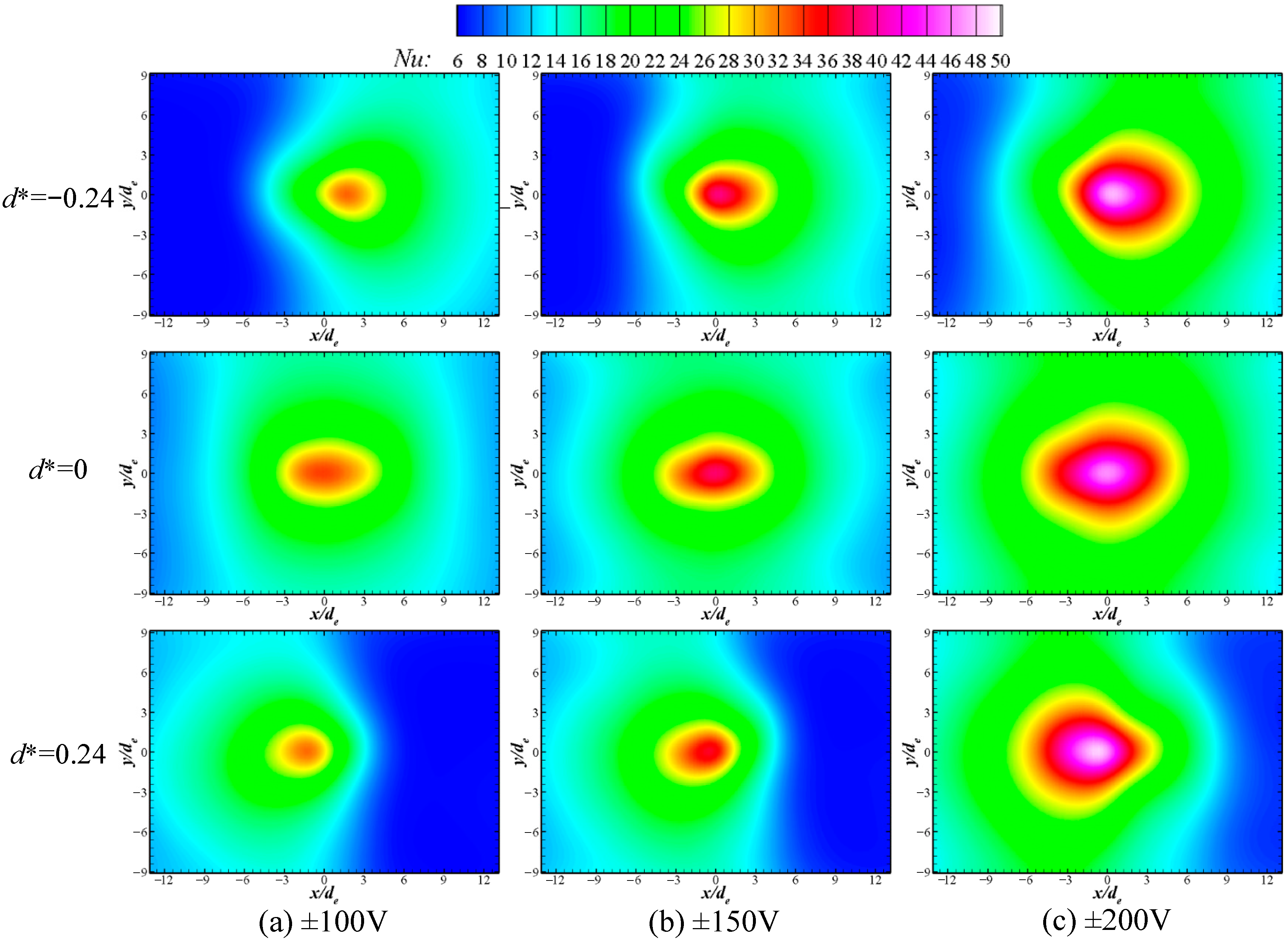
Figure 9 shows Nu distributions on impinged surface at different driving voltages and slider locations. It is indicated that for each slider location, the peak Nu and the high Nu region gradually increase with the increase in the driving voltage. The reason is that the primary jet velocity becomes high with the increase in the driving voltage, and thus the local heat transfer coefficient increases. The core of the high Nu region can move toward the center location, which is agreement with the variation trend of the vectoring angle with the increase in the driving voltage.
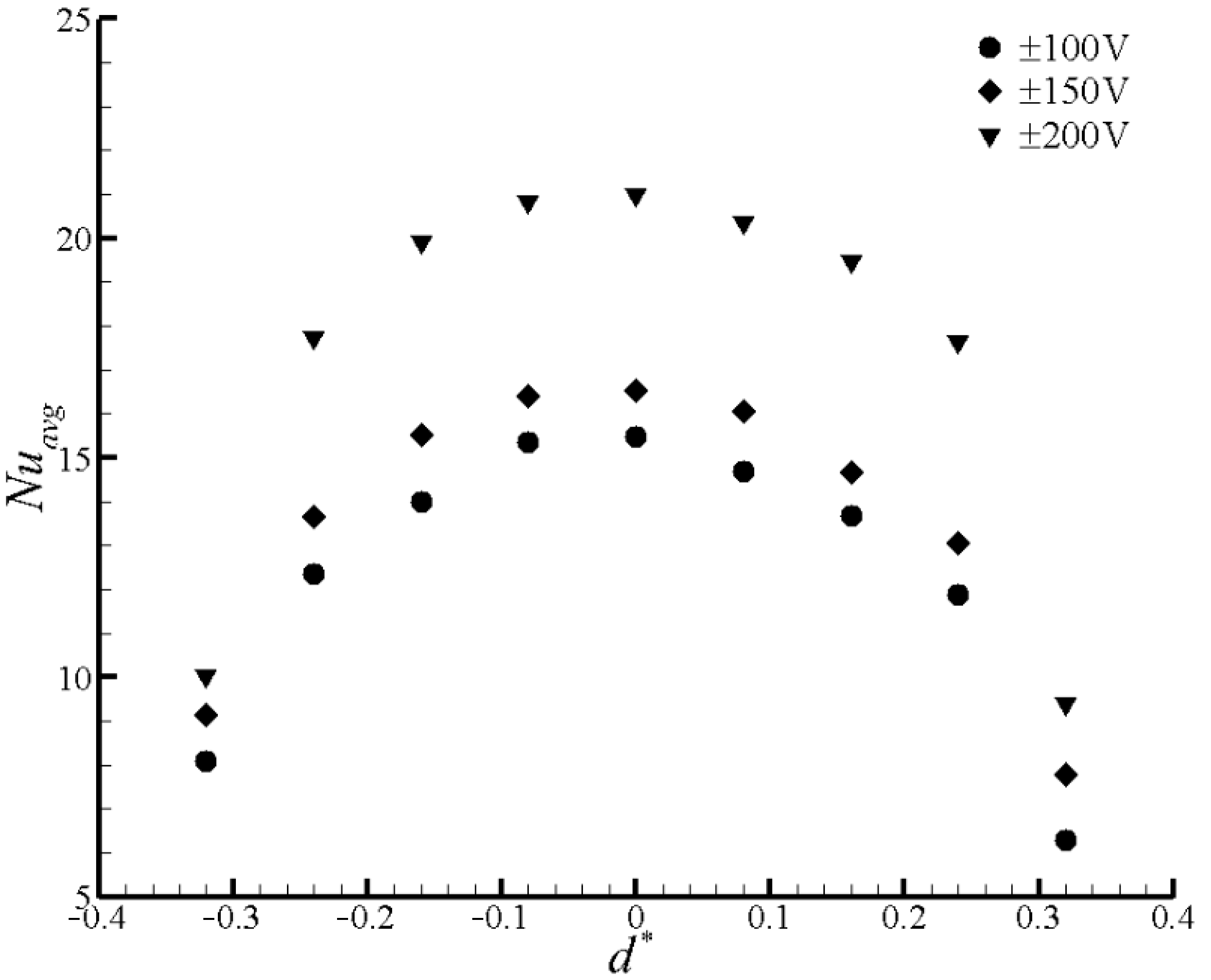
Nuavg at different driving voltages and slider locations are plotted in Figure 10. The curves indicate that Nuavg improves with the increase in the driving voltage at each slider location. It is attributed to the obvious increases in the peak Nu and the high Nu region (shown in Figure 9). For each driving voltage, there is one peak of Nuavg at the center location of the slider and decreases when the slider moves away from the center. The reason is that the primary jet velocity is so high at the center location of the slider that the choking effect occurs when the slider moves away from the center. As a result, the DSJ velocity reduces, as well as the heat transfer coefficient. Moreover, the impingement DSJ can transform to a cross flow owing to the vectoring deflection. Above two reasons make the whole cooling performance weak. Although a high driving can improve the cooling performance, the energy consumption also increases. The driving voltage should be selected by considering the energy utilization efficiency in the cooling applications.

4. Conclusions

The effects of slot location, driving voltage, and driving frequency on impingement flow field and cooling characteristics of vectoring DSJ are experimentally investigated. Conclusions are summarized as follows:
(1) The DSJ deflects toward the side of the slot with a greater cross section. The vectoring angle can be adjusted from 34.5° toward left to 29.5° toward right. The length of the impingement region is over two times as large as that of the normal DSJ. With the increase in |d*|, the maximum Nu increases first and then decreases. There are three local peaks of Nuavg at d* = 0 and ±0.28. Although maximum Nu at d* = ±0.08 and ±0.16 are larger than that at d* = 0, the Nuavg are smaller.
(2) The vectoring angle is lowest of 9.7° at the driving frequency of 350 Hz, but the peak Nu and high Nu area are obviously augmented. There is one local peak of Nuavg at 350Hz rather than three local peaks of Nuavg at 250 Hz and 450 Hz. The difference is that the maximum Nuavg of 250 Hz and 450 Hz, respectively, occurs at d* = 0 and at d* = ±0.24.
(3) With the increase in the driving voltage, the vectoring angle decreases from 46.9° to 22.2°, but the length of the impingement area is extended. There is one local peak of Nuavg at d* = 0 for each driving voltage.

Author Contributions

Conceptualization, X.D. and Z.L.; methodology, X.D. and W.H.; formal analysis, X.D. and Z.D.; investigation, X.D. and Q.L.; writing—original draft, X.D.; writing—review and editing, C.P. and Z.D. All authors have read and agreed to the published version of the manuscript.

Funding

This research was funded by the National Natural Science Foundation of China (grant numbers 11972369, 11872374) and the Science and Technology Innovation Program of Hunan Province (2021RC3075).

Data Availability Statement

Data available on request from the authors.

Conflicts of Interest

The authors declare no conflict of interest.

Nomenclature

Aeffectively heated area (mm2)
AΩintegration area (mm2)
dslot location (mm)
d1, d2width of two slots (mm)
decharacteristic length (mm)
d* slot dimensionless location
eθunit vector along the projected line
hconvective heat transfer W/(m2K)
Icurrent through the foil (A)
MaMach number
Nulocal Nusselt number
Nuavgarea-averaged Nusselt number
Qele, Qlossinput power and heat loss (W)
qnetnet removed heat flux (W/m2)
Soobjection function (m/s)
ui, wivelocity components along x, z axis
Ts, Tjimpingement surface and jet
temperature (°C)
Vvoltage across the foil (V)
Vccritical velocity (m/s)
Greek symbols
θoblique angle of projected line (°)
θ0vectoring angle (°)
λthermal conductivity (W/(m·K))
Subscripts
avgspatially-averaged
netnet
elcelectric
jjet
lossheat radiation loss
maxmaximum value
ssurface
Ωintegral domain
Acronyms
CCDcharge-coupled device
DSJdual synthetic jet
PIVparticle image velocimetry

References

  1. Glezer, A. Some aspects of aerodynamic flow control using synthetic-jet actuation. Philos. Trans. R. Soc. A Math. Phys. Eng. Sci. 2011, 369, 1476–1494. [Google Scholar] [CrossRef] [PubMed]
  2. Taylor, K.; Amitay, M. Dynamic stall process on a finite span model and its control via synthetic jet actuators. Phys. Fluids 2015, 27, 077104. [Google Scholar] [CrossRef]
  3. Wu, J.; Shen, M.; Jiang, L. Role of synthetic jet control in energy harvesting capability of a semi-active flapping airfoil. Energy 2020, 208, 118389. [Google Scholar] [CrossRef]
  4. Farrell, G.; Gibbons, M.; Persoons, T. Combined Passive/Active Flow Control of Drag and Lift Forces on a Cylinder in Crossflow Using a Synthetic Jet Actuator and Porous Coatings. Actuators 2022, 11, 201. [Google Scholar] [CrossRef]
  5. Luo, Z.; Zhao, Z.; Liu, J.; Deng, X.; Zheng, M.; Yang, H.; Chen, Q.; Li, S. Novel roll effector based on zero-mass-flux dual synthetic jets and its flight test. Chin. J. Aeronaut. 2022, 35, 1–6. [Google Scholar] [CrossRef]
  6. Tang, H.; Salunkhe, P.; Zheng, Y.; Du, J.; Wu, Y. On the use of synthetic jet actuator arrays for active flow separation control. Exp. Therm. Fluid Sci. 2014, 57, 1–10. [Google Scholar] [CrossRef]
  7. Zhao, G.; Zhao, Q. Parametric analyses for synthetic jet control on separation and stall over rotor airfoil. Chin. J. Aeronaut. 2014, 27, 1051–1061. [Google Scholar] [CrossRef] [Green Version]
  8. Wen, X.; Tang, H.; Liu, Y. Interaction of twin synthetic jets in attached and separated boundary layers: Effects of yaw angle and phase difference. J. Vis. 2018, 21, 949–963. [Google Scholar] [CrossRef]
  9. Rathay, N.; Amitay, M. Interaction of synthetic jets with a massively separated three-dimensional flow field. Phys. Rev. Fluids 2022, 7, 034702. [Google Scholar] [CrossRef]
  10. Xia, Q.; Zhong, S. Enhancement of inline mixing with lateral synthetic jet pairs at low Reynolds numbers: The effect of fluid viscosity. Flow Meas. Instrum. 2017, 53, 308–316. [Google Scholar] [CrossRef]
  11. Wang, L.; Feng, L.-H.; Wang, J.-J.; Li, T. Characteristics and mechanism of mixing enhancement for noncircular synthetic jets at low Reynolds number. Exp. Therm. Fluid Sci. 2018, 98, 731–743. [Google Scholar] [CrossRef]
  12. Zhang, B.; Liu, H.; Li, Y.; Liu, H.; Dong, J. Experimental Study of Coaxial Jets Mixing Enhancement Using Synthetic Jets. Appl. Sci. 2021, 11, 803. [Google Scholar] [CrossRef]
  13. Smith, B.L.; Glezer, A. Jet vectoring using synthetic jets. J. Fluid Mech. 2002, 458, 1–34. [Google Scholar] [CrossRef]
  14. Luo, Z.-B.; Xia, Z.-X.; Xie, Y.-G. Jet Vectoring Control Using a Novel Synthetic Jet Actuator. Chin. J. Aeronaut. 2007, 20, 193–201. [Google Scholar] [CrossRef] [Green Version]
  15. Ryota, K.; Yuki, W.; Yu, T.; Koichi, N.; Donghyuk, K.; Kotaro, S. Jet vectoring using secondary Coanda synthetic jets. Mech. Eng. J. 2020, 7, 20-00215. [Google Scholar]
  16. Yu, Y.; Simon, T.W.; Zhang, M.; Yeom, T.; North, M.T.; Cui, T. Enhancing heat transfer in air-cooled heat sinks using piezoelectrically-driven agitators and synthetic jets. Int. J. Heat Mass Transf. 2014, 68, 184–193. [Google Scholar] [CrossRef]
  17. Yeom, T.; Simon, T.; Zhang, M.; Yu, Y.; Cui, T. Active heat sink with piezoelectric translational agitators, piezoelectric synthetic jets, and micro pin fin arrays. Exp. Therm. Fluid Sci. 2018, 99, 190–199. [Google Scholar] [CrossRef]
  18. Gil, P.; Smyk, E.; Gałek, R.; Przeszłowski, Ł. Thermal, flow and acoustic characteristics of the heat sink integrated inside the synthetic jet actuator cavity. Int. J. Therm. Sci. 2021, 170, 107171. [Google Scholar] [CrossRef]
  19. Mohammadpour, J.; Salehi, F.; Lee, A.; Brandt, L. Nanofluid heat transfer in a microchannel heat sink with multiple synthetic jets and protrusions. Int. J. Therm. Sci. 2022, 179, 107642. [Google Scholar] [CrossRef]
  20. Maghrabie, H.M. Heat transfer intensification of jet impingement using exciting jets—A comprehensive review. Renew. Sustain. Energy Rev. 2021, 139, 110684. [Google Scholar] [CrossRef]
  21. Glezer, A.; Amitay, M. Synthetic jets. Annu. Rev. Fluid Mech. 2002, 34, 503–529. [Google Scholar] [CrossRef]
  22. Greco, C.S.; Cardone, G.; Soria, J. On the behaviour of impinging zero-net-mass-flux jets. J. Fluid Mech. 2016, 810, 25–59. [Google Scholar] [CrossRef]
  23. Pavlova, A.; Amitay, M. Electronic Cooling Using Synthetic Jet Impingement. J. Heat Transf. 2006, 128, 897–907. [Google Scholar] [CrossRef]
  24. Luis, S.L.; Alfonso, O. Vortex dynamics and mechanisms of heat transfer enhancement in synthetic jet impingement. Int. J. Therm. Sci. 2017, 112, 153–164. [Google Scholar]
  25. Greco, C.S.; Paolillo, G.; Ianiro, A.; Cardone, G.; de Luca, L. Effects of the stroke length and nozzle-to-plate distance on synthetic jet impingement heat transfer. Int. J. Heat Mass Transf. 2018, 117, 1019–1031. [Google Scholar] [CrossRef]
  26. Qiu, Y.-L.; Hu, W.-J.; Wu, C.-J.; Chen, W.-F. Flow and heat transfer characteristics in a microchannel with a circular synthetic jet. Int. J. Therm. Sci. 2021, 164, 106911. [Google Scholar] [CrossRef]
  27. Lyu, Y.-W.; Zhang, J.-Z.; Tan, J.-W.; Shan, Y. Impingement heat transfer on flat and concave surfaces by piston-driven synthetic jet from planar lobed orifice. Int. J. Heat Mass Transf. 2021, 167, 120832. [Google Scholar] [CrossRef]
  28. Lau, G.; Mohammadpour, J.; Lee, A. Cooling performance of an impinging synthetic jet in a microchannel with nanofluids: An Eulerian approach. Appl. Therm. Eng. 2021, 188, 116624. [Google Scholar] [CrossRef]
  29. Wang, L.; Feng, L.H.; Xu, Y.; Xu, Y.; Wang, J.J. Experimental investigation on flow characteristics and unsteady heat transfer of noncircular impinging synthetic jets. Int. J. Heat Mass Tran. 2022, 190, 122760. [Google Scholar] [CrossRef]
  30. Singh, P.K.; Renganathan, M.; Yadav, H.; Sahu, S.K.; Upadhyay, P.K.; Agrawal, A. An experimental investigation of the flow-field and thermal characteristics of synthetic jet impingement with different waveforms. Int. J. Heat Mass Transf. 2022, 187, 122534. [Google Scholar] [CrossRef]
  31. Smith, B.L.; Glezer, A. The formation and evolution of synthetic jets. Phys. Fluids 1998, 10, 2281–2297. [Google Scholar] [CrossRef]
  32. Luo, Z.-B.; Xia, Z.-X.; Liu, B. New Generation of Synthetic Jet Actuators. AIAA J. 2006, 44, 2418–2420. [Google Scholar] [CrossRef]
  33. Deng, X.; Xia, Z.-X.; Luo, Z.-B.; Li, Y.-J. Vector-Adjusting Characteristic of Dual-Synthetic-Jet Actuator. AIAA J. 2015, 53, 794–797. [Google Scholar] [CrossRef]
  34. Luo, Z.; Zhao, Z.; Deng, X.; Wangw4, L.; Xia, Z. Dual Synthetic Jets Actuator and Its Applications—Part I: PIV Measurements and Comparison to Synthetic Jet Actuator. Actuators 2022, 11, 205. [Google Scholar] [CrossRef]
  35. Deng, X.; Luo, Z.; Xia, Z.; Gong, W.; Wang, L. Active-passive combined and closed-loop control for the thermal management of high-power LED based on a dual synthetic jet actuator. Energy Convers. Manag. 2017, 132, 207–212. [Google Scholar] [CrossRef]
  36. Deng, X.; Luo, Z.-B.; Xia, Z.-X.; Gong, W.-J. Experimental investigation on the flow regime and impingement heat transfer of dual synthetic jet. Int. J. Therm. Sci. 2019, 145, 105864. [Google Scholar] [CrossRef]
  37. He, W.; Luo, Z.-B.; Deng, X.; Xia, Z.-X. Experimental investigation on the performance of a novel dual synthetic jet actuator-based atomization device. Int. J. Heat Mass Transf. 2019, 142, 118406. [Google Scholar] [CrossRef]
  38. He, W.; Luo, Z.-B.; Deng, X.; Peng, W.-Q.; Zhao, Z.-J. Experimental investigation on the vectoring spray based on a novel synthetic jet actuator. Appl. Therm. Eng. 2020, 179, 115677. [Google Scholar] [CrossRef]
  39. Luo, Z.-B.; Deng, X.; Xia, Z.-X.; Wang, L.; Gong, W.-J. Flow field and heat transfer characteristics of impingement based on a vectoring dual synthetic jet actuator. Int. J. Heat Mass Transf. 2016, 102, 18–25. [Google Scholar] [CrossRef]
  40. Moffat, R.J. Describing the uncertainties in experimental results. Exp. Therm. Fluid Sci. 1988, 1, 3–17. [Google Scholar] [CrossRef] [Green Version]
  41. Luo, Z.-B.; Xia, Z.-X. The mechanism of jet vectoring using synthetic jet actuators. Mod. Phys. Lett. B 2005, 19, 1619–1622. [Google Scholar] [CrossRef]
  42. Gallas, Q.; Holman, R.; Nishida, T.; Carroll, B.; Sheplak, M.; Cattafesta, L. Lumped Element Modeling of Piezoelectric-Driven Synthetic Jet Actuators. AIAA J. 2003, 41, 240–247. [Google Scholar] [CrossRef]
Figure 1. Experimental device.
Actuators 11 00376 g001
Figure 2. Velocity vector maps, contours, and vectoring angles at different slider locations.
Actuators 11 00376 g002
Figure 3. Nu contours on the impingement surface at different slider locations.
Actuators 11 00376 g003
Figure 4. Variations of Nu and Nuavg.
Actuators 11 00376 g004
Figure 5. Velocity vector maps, contours and vectoring angles at different driving frequencies.
Actuators 11 00376 g005
Figure 6. Nu contours at different driving frequencies and slider locations.
Actuators 11 00376 g006
Figure 7. Nuavg variations with the driving frequency and the slider location.
Actuators 11 00376 g007
Figure 8. Velocity vector maps, contours and vectoring angles at different driving voltages.
Actuators 11 00376 g008
Figure 9. Nu contours at different driving voltages and slider locations.
Actuators 11 00376 g009
Figure 10. Nuavg variations with driving voltage and slider location.
Actuators 11 00376 g010
Publisher’s Note: MDPI stays neutral with regard to jurisdictional claims in published maps and institutional affiliations.