Article

Model-Based Systems Engineering Approach for the First-Stage Separation System of Launch Vehicle

Shanghai Aerospace Systems Engineering Institute, Shanghai 201109, China
*
Author to whom correspondence should be addressed.
Actuators 2022, 11(12), 366; https://doi.org/10.3390/act11120366
Submission received: 21 October 2022 / Revised: 29 November 2022 / Accepted: 1 December 2022 / Published: 7 December 2022
(This article belongs to the Special Issue Dynamics and Control of Aerospace Systems)

Abstract

:
This paper proposes a model-based systems engineering (MBSE) methodology to design a first-stage separation system for a launch vehicle. It focuses on the whole process of system modeling, such as modeling the requirements analysis, logical architecture design, physical architecture design, and system verification and validation. Finally, the component requirements are obtained as the baseline for the component design. Requirements analysis is carried out by identifying stakeholders with the cycle modeling for this system and the use of case modeling to ensure that the requirements are comprehensive and correct. Additionally, the standard system requirements are obtained and baselined. Based on system requirements, the trade-off analysis of hierarchical functional architecture and key indicators was mainly carried out to design the logical architecture. Once the logical architecture was decided, the logical architecture was allocated to the physical architecture to be implemented. Several physical architectures are analyzed hierarchically to seek the optimal architectures. Then, other CAE analysis tools were integrated to verify the physical architecture design. All these processes are modeled and integrated as the authority system model, which benefits the system engineer for managing the requirement changes easier and rapidly provides multi-views for different roles.

1. Introduction

Launch vehicles play a fundamental and critical role for human beings to explore space, and their technical capabilities determine the depth and extent of a country’s space exploration activities. In recent years, new technologies such as full three-dimensional computer-aided design (CAD) and product data management (PDM) platforms have been widely used in the development of next-generation launch vehicles [1], which have improved the product development efficiency of enterprises. In the field of system design, however, the document-based systems engineering method is still too dominant to be adopted, which restricts the complex system design capabilities. Therefore, it is urgent to explore and apply a new model-based system design paradigm to improve the leap-forward development and manage innovative and complex launch vehicle system designs [2].
As a promising technology to manage system design better, MBSE is a hotspot technology for the complex system development paradigm [3]. MBSE takes system modeling as its core and supports the processes of system requirements capture, function analysis, architecture design, comprehensive performance simulation, etc. Moreover, the system model is integrated with the other models developed in the life cycle and works as the authority model, which is an important way to decrease misunderstanding and improve the design consistency for complex systems [4]. Based on lots of industry practice, several MBSE methodologies were proposed, such as MagicGrid, Arcadia, and Harmony SE. These methodologies are a little abstract at the top level, which is a little difficult to guide in engineering projects [5]. David Kalsow and etc. developed the CubeSat project as a reference model using the MBSE approach from 2012 to 2018 [6,7,8,9,10]. These papers introduced an MBSE roadmap for a satellite project [7]. A mission-specific satellite model was established [8], while a correspondent validation strategy was developed [9]. All the information is a little fuzzy to be projected to the true engineering system design for the whole project. Moreover, logical architecture and physical architecture are not clearly stated in the CubeSat reference model [11]. This paper aims to develop the first-stage separation system of launch vehicles using the MBSE approach from the viewpoint of a system engineer. Additionally, it clearly introduces the full process, including requirement analysis, logical architecture design, physical architecture design, the validation and verification of these designed architectures, and finally, the component requirements are obtained. Moreover, while the whole authority model is built, there are lots of scenarios to use this system model in, such as requirement change analysis and providing different views for different roles and applications.

2. Research Progress

The concept of model-based design, model-based development, and model-based definition started with CAD and CAE in the 1960s. With the development of the CAD model as the baseline for system engineering, the PDM platform was developed in the 1980s, and PDM was integrated with CAD to improve the configuration management in collaboration with the model-based design. However, the activity of the system design is still document based, which is not formalized to support future intelligent design. In 2007, the model-based system design concept was explored, applied, and developed. A new paradigm named MBSE has been developed to cope with the increasing complexity of space missions and the development of complex space products.
At present, there are three leading ecosystems of MBSE [12]. One ecosystem is the OMG ecosystem. This ecosystem is led by the INCOSE association, supported by the Dassault core platform, and is applied to leading enterprises such as NASA, Boeing, Lockheed Martin, etc., which develop lots of achievements such as standards, tools, and lots of applications [13]. Standards include SysML language, SysPhs, methodology, etc. Tools include Magicdraw, Rhaposody, EA, etc. [14]. Another ecosystem is the France ecosystem. This ecosystem is driven by the PolarSys organization, relying on the application practices of leading enterprises, such as Thales and Siemens, and is supported by the core platform of Siemens [15]. A series of standard achievements, such as Capella, have been formed, and the Thales ecology has been continuously expanded [16]. The third ecosystem is the ISO ecosystem. This ecosystem is driven by the ISO organization and relies on the application practice of some leading enterprises, such as NASA and General Motors, with OPM as the core tool support [17,18]. A series of standard achievements, such as the OPL language, are formed to continuously expand the OPM ecosystem [19].
The most important feature of the ecosystem is the trinity system, which combines academic research in institutions such as INCOSE, software tool development in tool suppliers such as Dassault, and engineering applications in industries such as NASA and Dassault Aviation. The three-in-one system enhances each other and grows together to become the industry benchmark in their respective fields [20].
The exploration of the MBSE development paradigm in China is still at a preliminary stage. Along with the successful practice of MBSE in other countries, the exploration of the MBSE development paradigm in China has also entered a prosperous state, among which the Aviation Industry Corporation of China (AVIC, Beijing, China), Tsinghua University(Beijing, China), Beihang University(Beijing, China), China Aerospace Science and Industry Corporation Limited (CASIC, Beijing, China) and China Aerospace Science and Technology Corporation (CASC, Beijing, China)have carried out a lot of practical exploration work, forming a series of theoretical methods, software tools, practical cases, and other achievements [21].

3. The First-Stage Separation System Design Based on MBSE

3.1. The First-Stage Separation System

The separation system is an important sub-system of the launch vehicle. Its main function is to separate the parts of the rocket that have completed their scheduled work during the flight. By reducing the mass that is useless in further flight, the mass characteristics of the launch vehicle can be improved, and its carrying capacity can be increased. The first-stage separation system is mainly composed of three parts according to the functions of stage separation, namely, the connecting and unlocking device, the impulse separation device, and the detonation device. As a part of the launch vehicle, the separation system is related to every system on the launch vehicle, such as the general design, electrical system, power system, and structural system. Therefore, the design of the separation system has a wide representation in the launch vehicle design process.

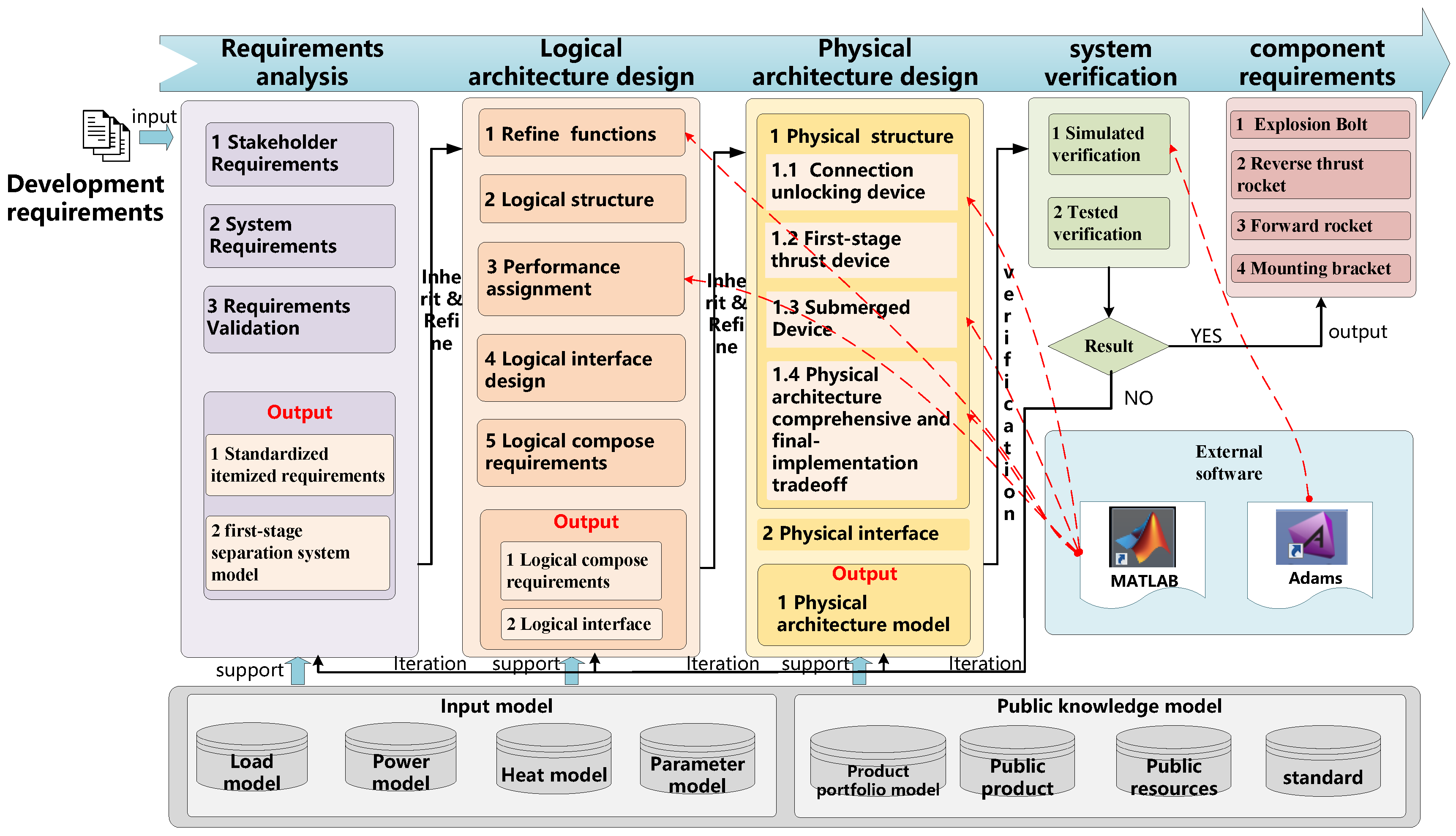
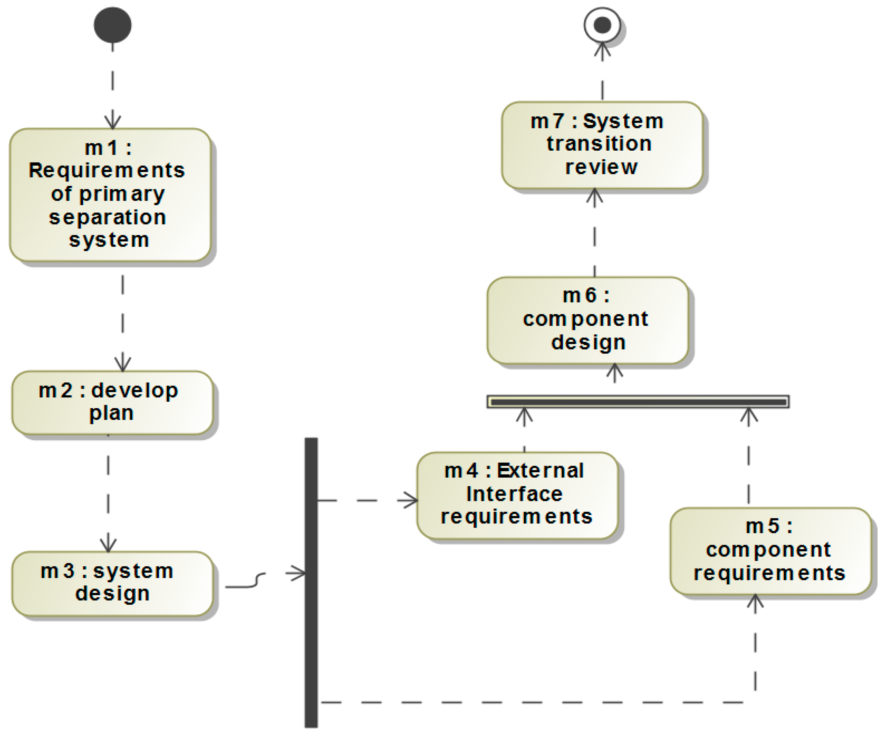
3.2. Modeling Framework of the Separation System Adopting MBSE Approach

The MBSE modeling approach is a collection of related processes, methods, and tools that support the systems engineering regulations in a model-driven environment. It is the top-level guidance for system design. The magic grid methodology is typically adopted and applied to NASA’s spacecraft and Dassault Aviation’s aircraft. However, the public magic grid methodology is abstracted and described from the modeling approach viewpoint. This paper tailors the magic grid methodology and proposes the model framework and modeling process for the first-stage separation system design viewpoint, as shown in Figure 1.

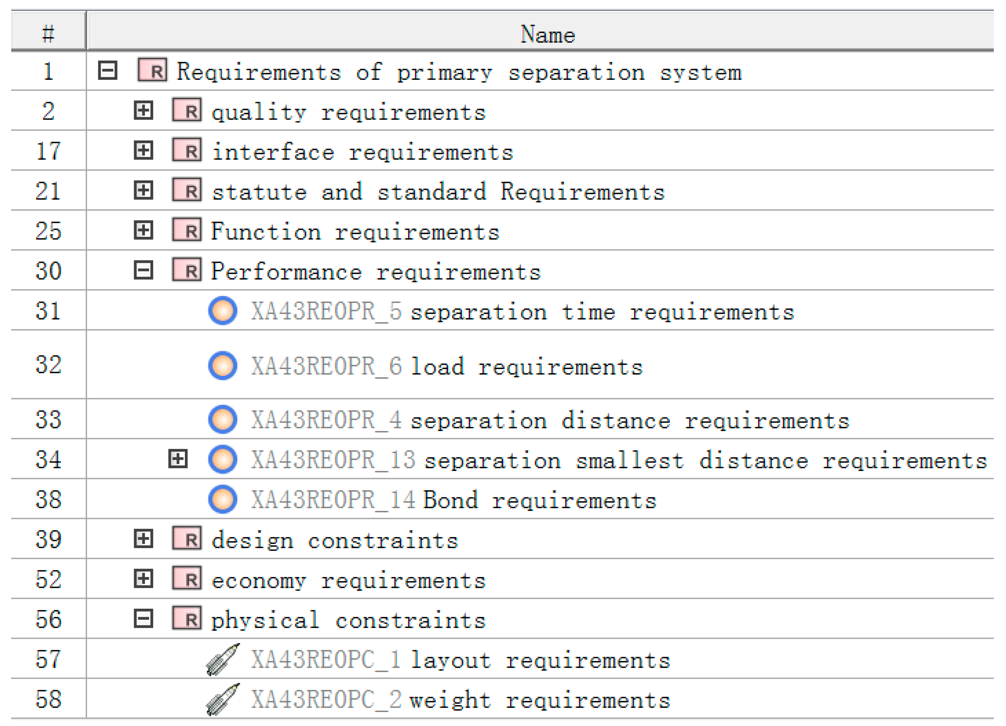
3.3. Requirements Analysis of the First-Stage Separation System

Compared with traditional requirements analysis, requirements analysis by the MBSE approach formalizes the requirements expression, provides the stakeholder and full cycle viewpoint to check the requirements, builds the operational scenario to capture requirements, and flows down from the stakeholders’ requirements to system requirements and then to component requirements by quantitative analysis, architecture trade-off, and concept design. All these processes are standardized and formalized through SysML language.
The process of requirements analysis and modeling based on MBSE is as follows: first, we should capture requirements in three ways. One way is to identify the stakeholders to check who proposed the requirements, as shown in Figure 2. The second way is to define the life cycle process to check when the requirements were proposed, as shown in Figure 3. The third way is to design the scenario to check where the requirement was proposed, as shown in Figure 4. The stakeholders’ model, lifecycle process model, and use case model are baselined for requirement analysis. as shown in Figure 2, Figure 3 and Figure 4. Secondly, once the requirements are fully captured, the requirements should be itemized and standardized, following the industry standard specification. Thirdly, any functional requirements should be checked, and the performance of the function should be evaluated. Through the functional requirements comparison matrix with performance requirements, there are some performance requirements figured out. For example, tall functions in the first-stage separation system need to work safely under complex force constraints such as the first-stage engine thrust, the second-stage engine thrust, the electrical connector pull-out force, and the trachea pull-out force, etc. In order to validate and verify the requirements of safety separation, the minimum separation gap should be quantitively defined according to the experience or design mechanism. Through the continuous iteration of the above process, 58 requirements for the first-stage separation system were finally formed and can be used as the design basis for the separation system, as shown in Figure 5.

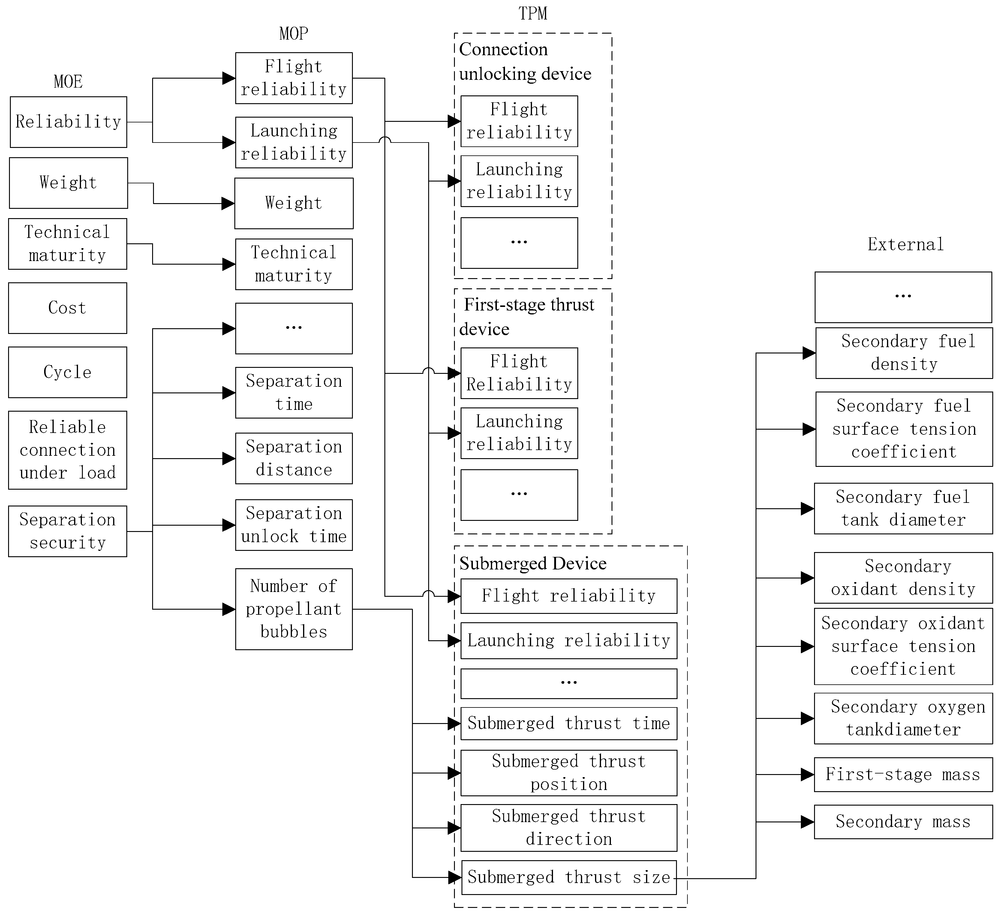
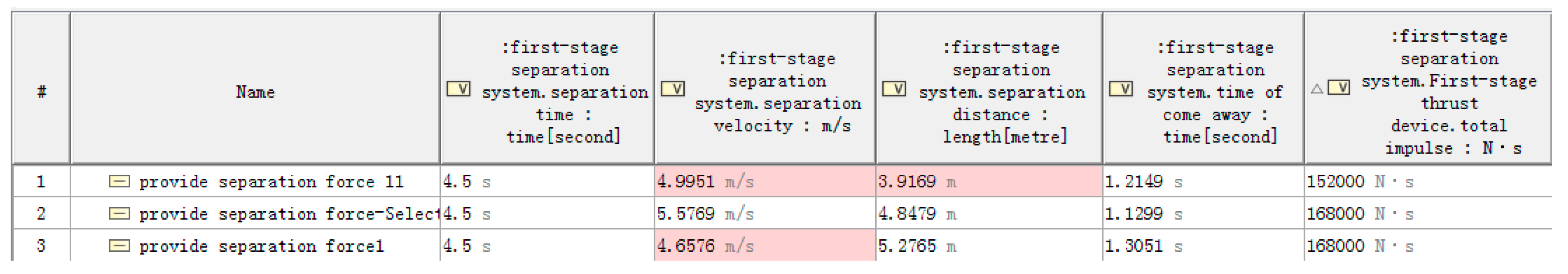
3.4. Logic Architecture Design of the Separation System for Key Parameters

The main purpose of the logic architecture design is to obtain the best system architecture among lots of alternatives. The traditional logical architecture design using the document-based systems engineering paradigm usually selects the empirical alternative and calculates the total impulse and number of rockets in multiple groups through simulation verification. The MBSE approach emphasizes the forward design process. The process is to analyze and refine the functions, perform the comprehensive clustering of functions to obtain components, and obtain the optimal composition of each component through index allocation. Then, the interaction and combination of functions are synthesized, and the interface design is performed. Finally, the optimal alternatives are obtained. For this system, the modeling process is as follows:
Firstly, the top-level functionality is obtained based on the system requirements, and the functional architecture is defined. When analyzing the operational scenario for the top-level functionality, there are two alternative logical architectures. One is separation once the other is separation twice. Based on the effective criteria, these two alternatives are traded off quantitatively, and then the proposal of separation once is better than the other, which is shown in Figure 6 and Figure 7.
To design the first-stage separation system of the launch vehicle, we should identify the measure of effectiveness (MOE) from the system requirements. MOE includes the reliability, weight, cost, and safety separation. etc. Then, MOE should be transformed into the measure of performance (MOP), which should be baselined for the index allocation. For example, the safety separation should be refined by the separation time, separation gap, and so on. Finally, all the MOP should be allocated to technical performance measures, which could be allocated to logical components. The index flows down from MOE to MOP and from MOP to TPM is complicated because of the complicated system, as shown in Figure 8. Anyway, there are three core parameters, such as the connection forces to combine the first and second stages of the rocket, the thrust force to throw away the first sub-stage, and the push force to ensure that the secondary propellant sinks to the bottom. There are still several alternatives for the parameter flowing down from the top level to the low level. The system engineer would build the evaluation criteria and then select the best alternative through trade-off analysis. Finally, the core parameters are calculated, as shown in Figure 9. Additionally, the three core parameter values are as follows:
  • The connection device needs to provide a connection force greater than 940,286 N.
  • The first thrust device needs to provide a total axial impulse greater than 168,000 N/s.
  • The device, to ensure propellant sinking to the bottom, should provide an axial thrust force greater than 293 N.
By integrating specific functions and assigning them to the logical entities and logical interfaces, the logical architecture of the first-stage separation system can be built, which is shown in Figure 10, and all of the indexes have been allocated to each logical component. As a result, the interfaces and parameters of the logical architecture will be determined. Hence, the logical architecture is shown in Figure 10.

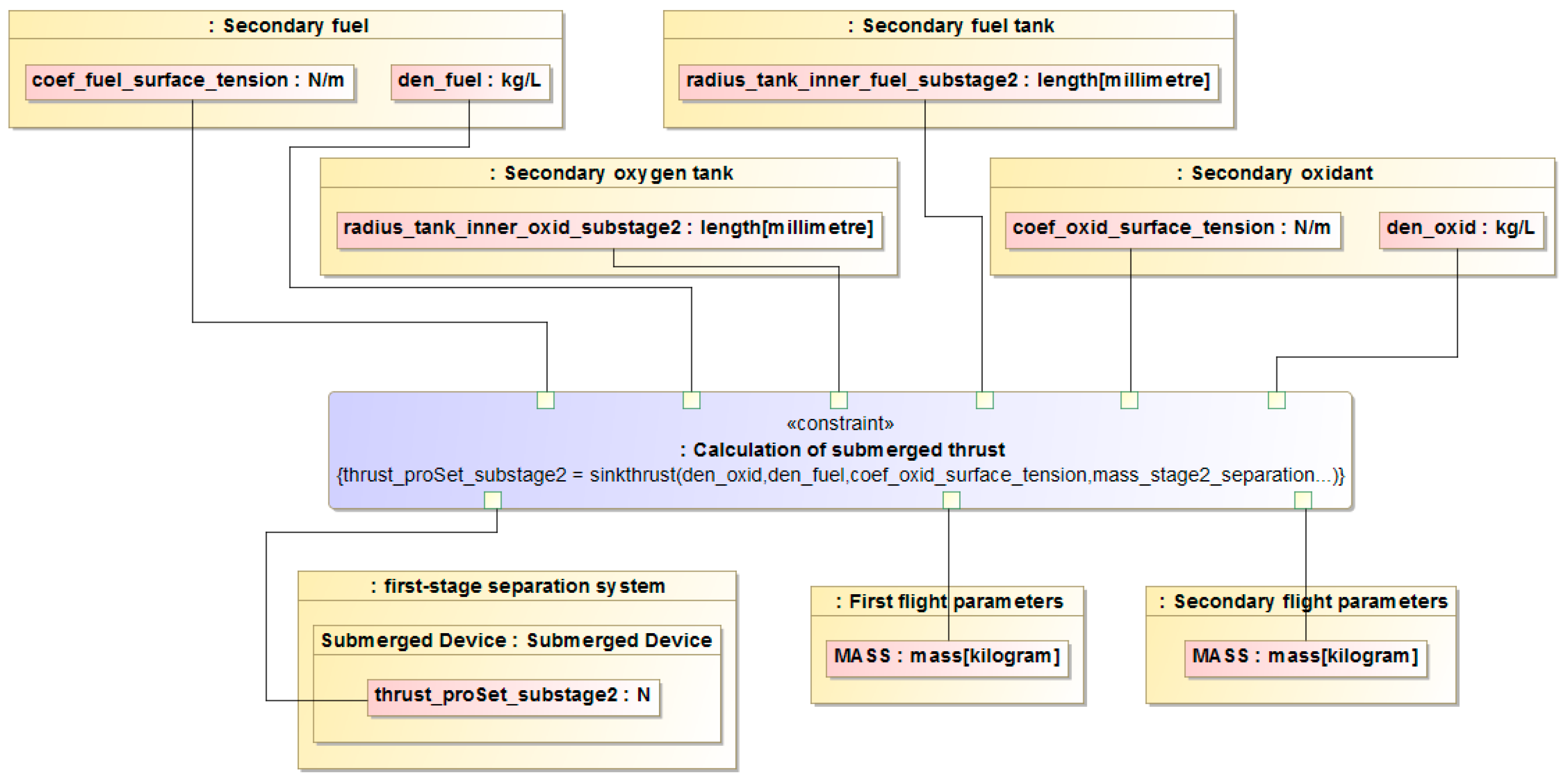
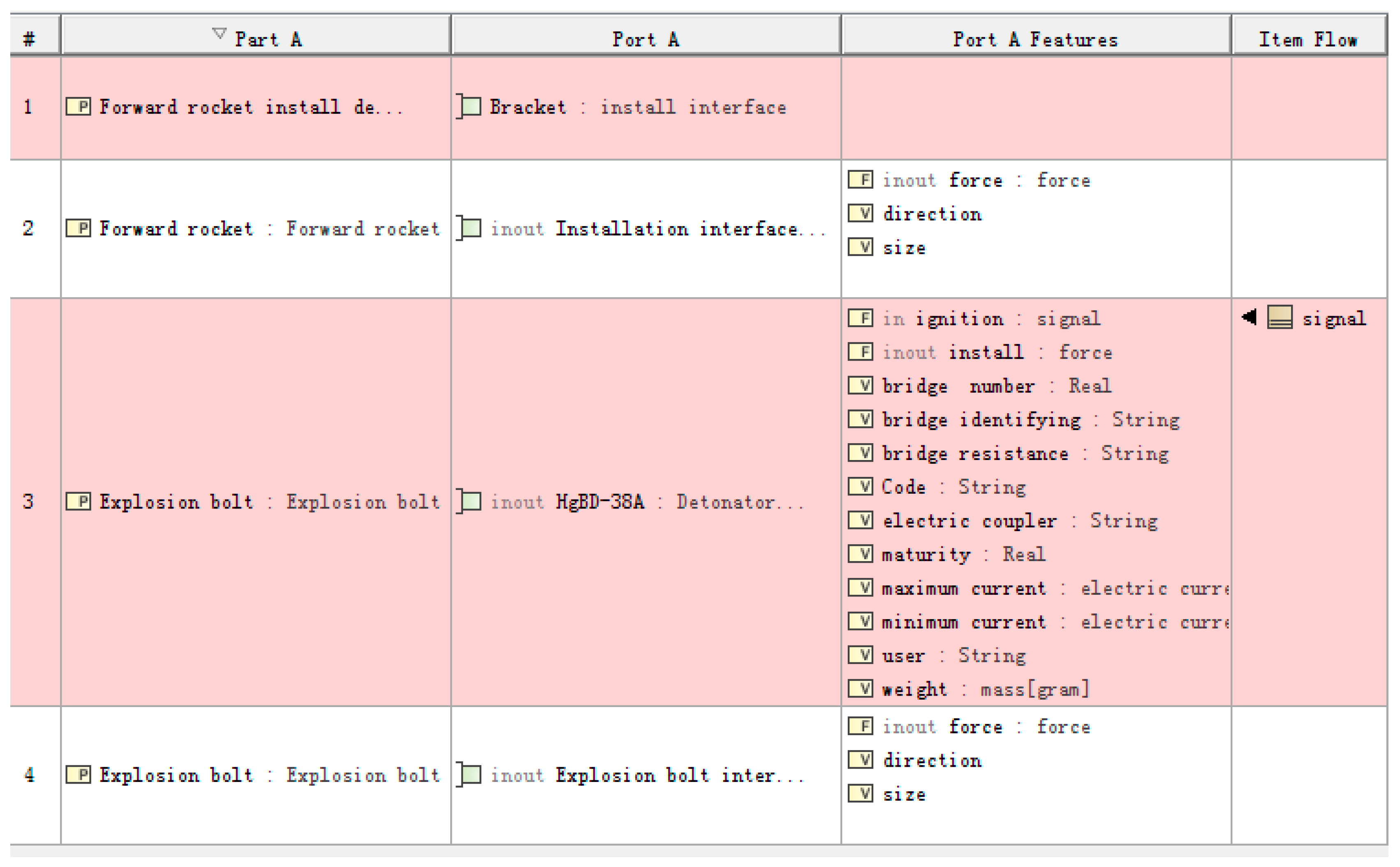
3.5. Physical Architecture Design of the First-Stage Separation System Based on Model Selection Analysis

The physical architecture design of the first-stage separation system is a set of product units that achieve the required functionality and performance of the system within the performance constraints specified by the logical architecture. The physical architecture design is, therefore, the process of implementing a solution based on the logical architecture design.
Compared with the traditional separation system design, the physical architecture design of the first-stage separation system based on MBSE has a similar work content. It mainly completes the trade-off analysis of the physical implementation options, as well as the product selection analysis, and performs the comprehensive analysis of the physical composition to form the final physical architecture design results. Finally, the final selection results are taken as the basis for forming the final physical architecture design result and creating the interface model, and organizing and summarizing the interface information.
The specific modeling process is as follows: create a physical architecture model according to the logical architecture and establish a model of the inheritance relationship from the physical architecture to the logical architecture. First, a trade-off analysis of the implementation of the separation forces is carried out. By the quantitative trade-off analysis of the pneumatic connection unlocking device, explosive bolts, and linear connection unlocking device, the explosive bolts are chosen as the final solution. Then, the trade-off analysis of the types of explosive bolts is carried out, including the BLS-300C24-1 explosive bolt and BLS-300C24-2 explosive bolt. After quantitative trade-off analysis, BLS-300C24-1 is selected. After a series of analyses, the first-stage separation system physical architecture scheme is determined, as shown in Figure 11. Finally, the physical architecture design is completed by defining the physical interface model.

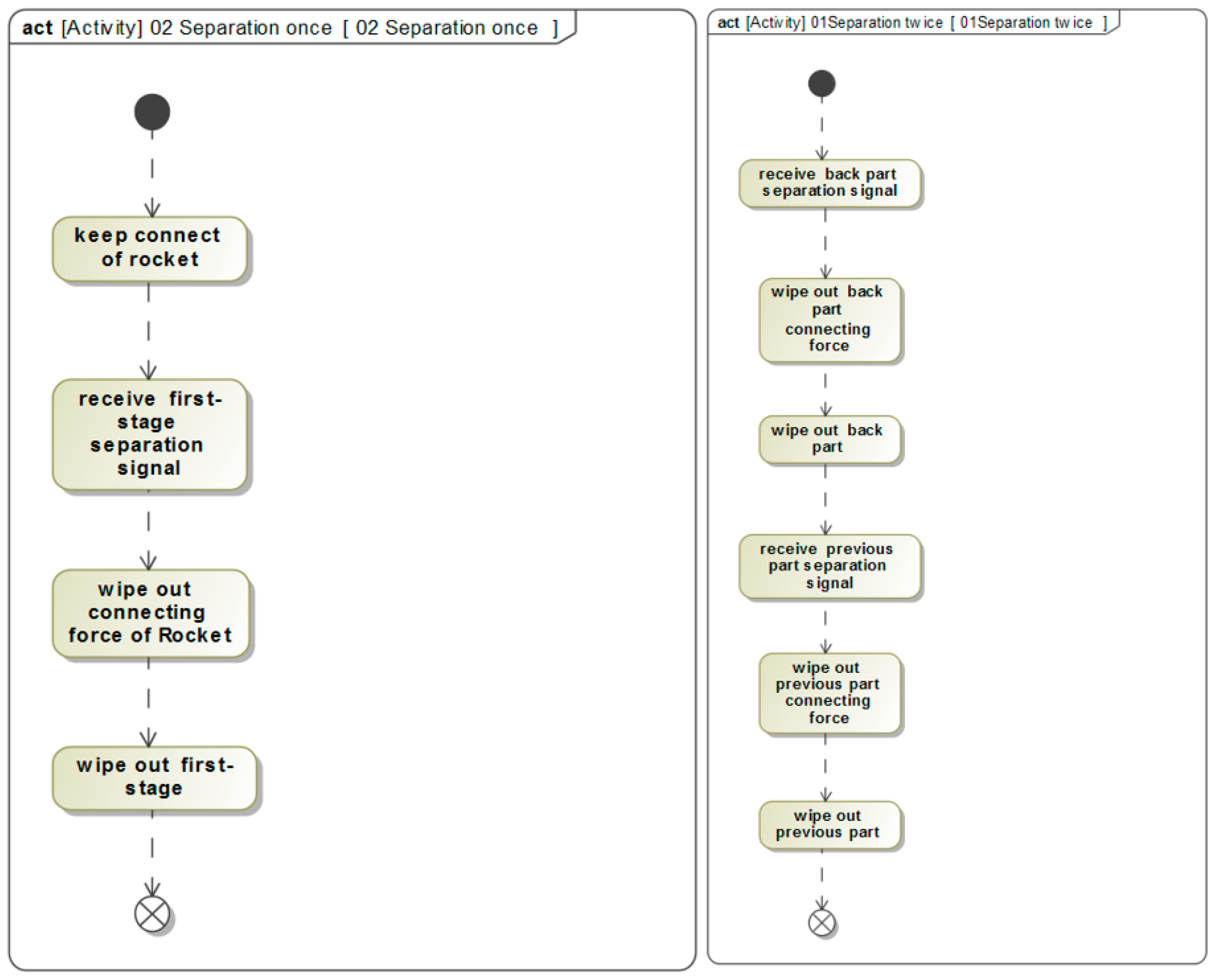
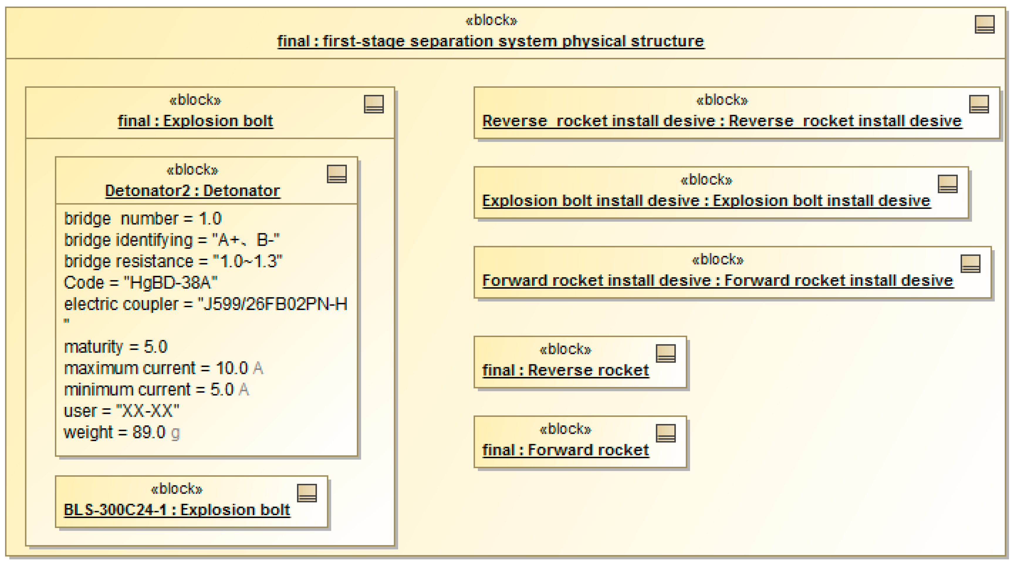
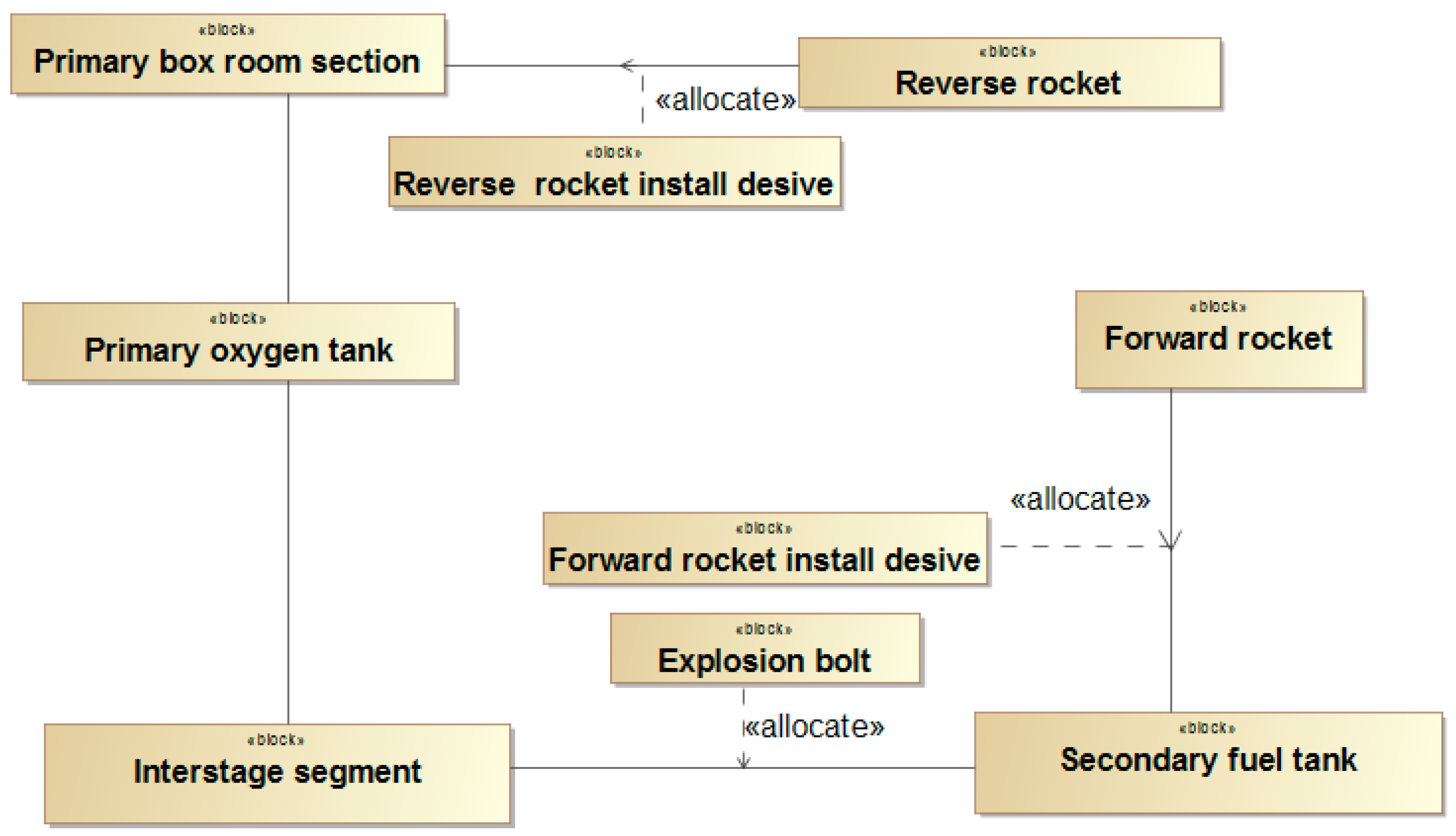
3.6. Validation and Verification of the First-Stage Separation System Based on the Object-Oriented Method

Compared with the traditional design method, this model-based first-stage separation system verification adopts “object-oriented concepts” that take the physical architecture as the test object, and validates objects from the functional verification, performance index verification, and interface verification.
In the functional verification process, the interaction between the components and the external system in the main functional scenario of the system is established using the SysML sequence diagram to complete the traditional time sequence design process. The mapping between the functions and requirements is described by establishing a relationship matrix (RM) to check that each function meets the requirements.
The verification of the performance indicators is the core element of the validation of the separation system. The key performance parameters for the separation process, including the separation distance, separation gap, and separation speed, need to be analyzed by ADAMS for rigid body dynamics. In this case, the standard data files and interface models are used to integrate the system model with the CAE simulation model.

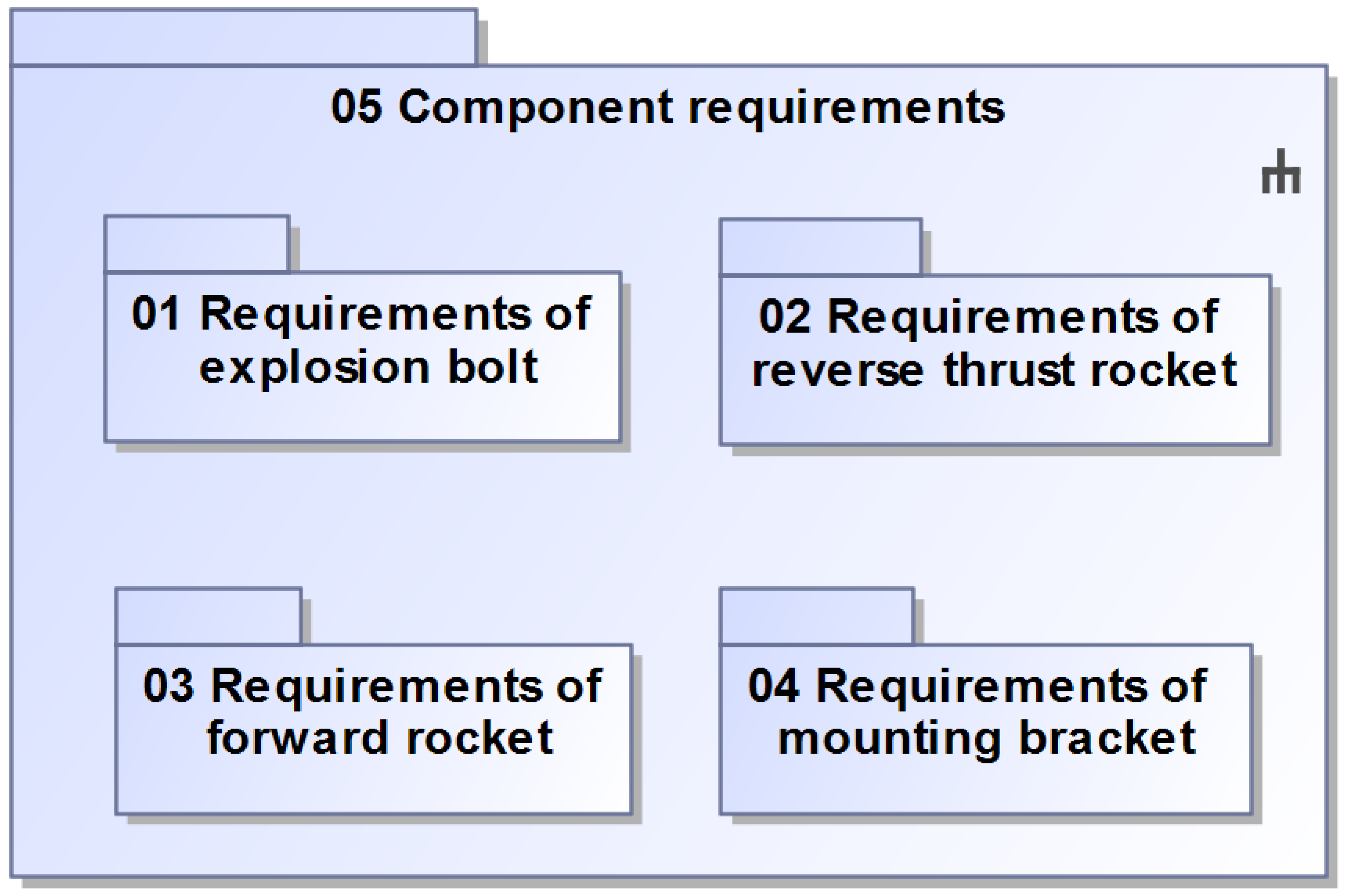
3.7. Component Requirements for the First-Stage Separation System

After the architecture of the separation system is verified, the functions, indicators, interface models, and itemized requirements of each component can be generated from the system model. The component model and itemized requirements are baselined, and then the component designer takes it as the design input to move to the next step.

4. The Application Advantages of Using System Model in Engineering Activity

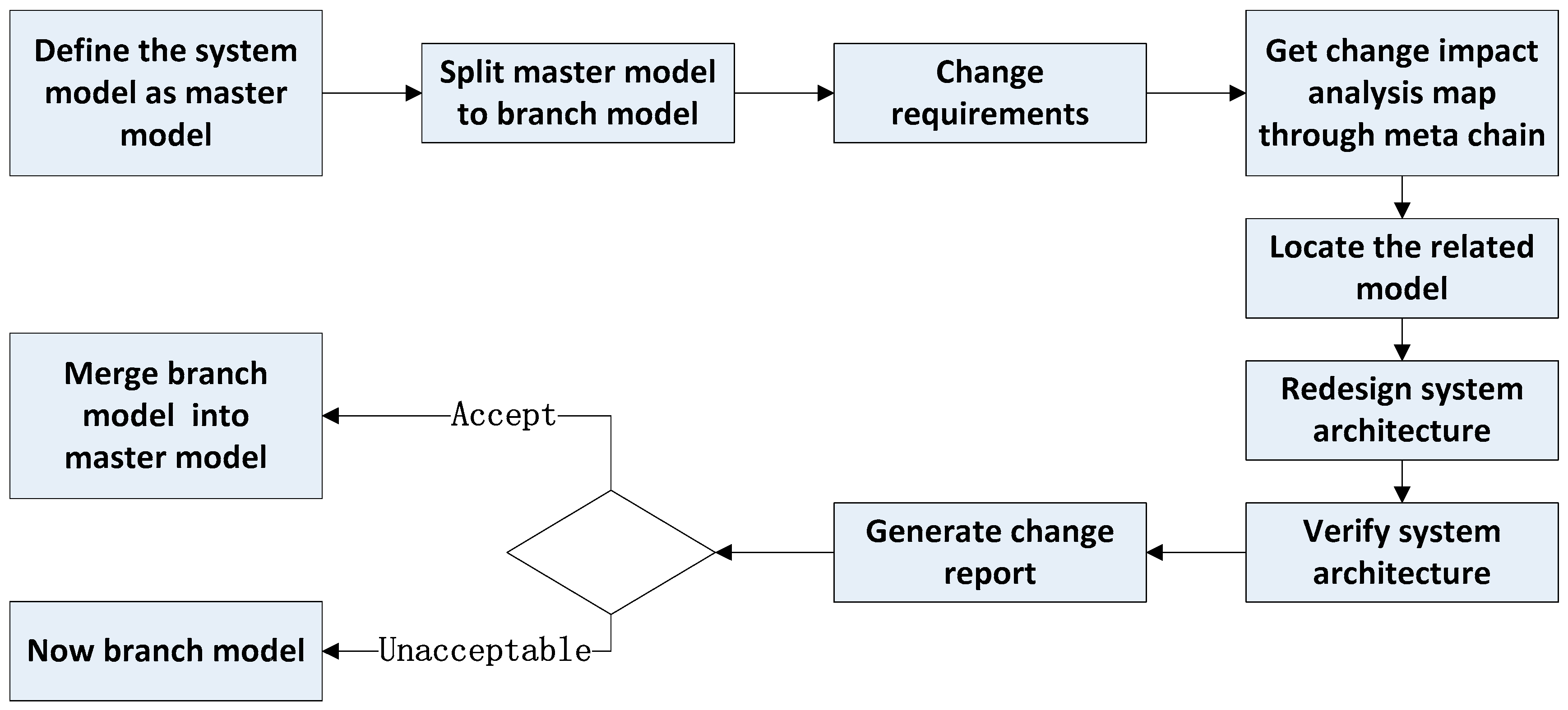
4.1. Requirement Changes Analysis Using the System Model

With t, the integrated system model, we can build the requirement change impact analysis process to support the system design, as shown in Figure 12. This integrated system model is split into two models. One model is the master model, and the other is the branch model. The branch model supports the requirement change analysis. Once the requirement is changed, the change impact domain analysis map is figured out through the meta-chain in the branch model. It is easier and quicker to locate the chain between the changed requirements and the related model elements, such as the architecture design model, verification model, and so on. Then, the related models are redesigned. Moreover, the verification model is simulated again, as shown in Figure 13. Compared with the master model and branch model, the change report is generated for the system engineer. Based on these two results analyses, the changed requirements and new system architecture are decided to be acceptable or not. If the change is accepted, the branch model will be merged with the master model, as shown in Figure 12 and Figure 13.

4.2. Multi-Views Based on Authority Model

The integrated system model is a full-feature model which includes the system design process and system definition. Different stakeholders from different viewpoints can obtain various design view models from this system model. In the design process of the separation system, the interface control document, component requirements, flight procedures, system layout, etc., can be generated from the system model automatically, as shown in Figure 14, Figure 15, Figure 16 and Figure 17.

5. Conclusions

In this paper, the MBSE approach is applied to design the first-stage separation system. This paper tailored the magic grid methodology and proposed the modeling framework, which could be suitable for similar dynamic and transient systems, such as the rocket system. A set of modeling for the requirements of the flow down is demonstrated; the logical architecture and physical architecture are designed and follows the framework. Moreover, the system design is verified and validated by integrating the Adams simulation model, which makes the system model as the authority model. In addition, using this system model in a requirement change analysis scenario shows that the MBSE approach has obvious advantages for system engineering. Of course, it is more rapid to provide multi-view information for other users, which is better than a document-based approach.

Author Contributions

W.Z. and Z.L. completed preliminary research; Z.L. conceived and wrote the paper; X.L., Y.J., Q.W. and R.H. supervised the overall work and reviewed it. All authors have read and agreed to the published version of the manuscript.

Funding

This work was funded by the National Key R&D Program of China under Grant 2020YFB1708100 (system modeling theory for complex product development integrated the process of design, manufacture and service), and the “14th Five-Year Plan” Major program of Advance research on Civil Aerospace Technology under Grant D020101 (design and verification technology of aerospace transportation system under MBSE paradigm).

Institutional Review Board Statement

Not applicable.

Informed Consent Statement

Not applicable.

Data Availability Statement

Not applicable.

Conflicts of Interest

The authors declare no conflict of interest.

References

  1. Redmon, J.; Shirley, M.; Kinard, P. A Large-Scale Design Integration Approach Developed in Conjunction with the Ares Launch Vehicle Program. In Proceedings of the 50th AIAA Aerospace Sciences Meeting including the New Horizons Forum and Aerospace Exposition, Nashville, TN, USA, 9–12 January 2012; p. 881. [Google Scholar]
  2. Henderson, K.; Salado, A. Value and benefits of model-based systems engineering (MBSE): Evidence from the literature. Syst. Eng. 2021, 24, 51–66. [Google Scholar] [CrossRef]
  3. Wade, J.; Verma, D.; McDermott, T.; Boehm, B. The SERC 5-year technical plan: Designing the future of Systems Engineering Research. In Proceedings of the Ninth International Conference on Complex Systems Design & Management, Paris, France, 18–19 December 2018; Volume 1, p. 241. [Google Scholar]
  4. Mann, C.J.H. A practical guide to SysML: The systems modeling language. Kybernetes 2009, 38, 989–994. [Google Scholar] [CrossRef] [Green Version]
  5. Huldt, T.; Stenius, I. State-of-practice survey of model-based systems engineering. Syst. Eng. 2019, 22, 134–145. [Google Scholar] [CrossRef]
  6. Kaslow, D.; Ayres, B.; Cahill, P.T.; Hart, L. A model-based systems engineering approach for technical measurement with application to a CubeSat. In Proceedings of the 2018 IEEE Aerospace Conference, Big Sky, MT, USA, 3–10 March 2018; pp. 1–10. [Google Scholar]
  7. Kaslow, D.; Anderson, L.; Asundi, S.; Ayres, B.; Iwata, C.; Shiotani, B.; Thompson, R. Developing a cubesat model-based system engineering (mbse) reference model-interim status. In Proceedings of the 2015 IEEE Aerospace Conference, Big Sky, MT, USA, 7–14 March 2015; pp. 1–16. [Google Scholar]
  8. Kaslow, D.; Ayres, B.; Cahill, P.T.; Hart, L.; Yntema, R. Developing a CubeSat Model-Based Systems Engineering (MBSE) Reference Model—Interim Status #3. In Proceedings of the IEEE Aerospace Conference, Big Sky, MT, USA, 4–11 March 2017. [Google Scholar]
  9. Kaslow, D.; Ayres, B.; Cahill, P.T.; Hart, L.; Levi, A.G.; Croney, C. Developing an mbse cubesat reference model–interim status# 4. In Proceedings of the 2018 AIAA SPACE and Astronautics Forum and Exposition, Orlando, FL, USA, 17–19 September 2018; p. 5328. [Google Scholar]
  10. Kaslow, D.; Madni, A.M. Validation and Verification of MBSE-Compliant CubeSat Reference Model; Disciplinary Convergence in Systems Engineering Research; Springer: Cham, Switzerland, 2018; pp. 381–393. [Google Scholar]
  11. Kaslow, D.; Cahill, P.T.; Ayres, B. Development and application of the CubeSat system reference model. In Proceedings of the 2020 IEEE Aerospace Conference, Big Sky, MT, USA, 7–14 March 2020; pp. 1–15. [Google Scholar]
  12. De Saqui-Sannes, P.; Vingerhoeds, R.A.; Garion, C.; Thirioux, X. A taxonomy of MBSE approaches by languages, tools and methods. IEEE Access 2022, 10, 120936–120950. [Google Scholar] [CrossRef]
  13. Holladay, J.B.; Knizhnik, J.; Weiland, K.J.; Stein, A.; Sanders, T.; Schwindt, P. MBSE Infusion and Modernization Initiative (MIAMI):“Hot” benefits for real NASA applications. In Proceedings of the 2019 IEEE Aerospace Conference, Big Sky, MT, USA, 2–9 March 2019; pp. 1–14. [Google Scholar]
  14. Estefan, J.A. Survey of model-based systems engineering (MBSE) methodologies. Incose MBSE Focus Group 2007, 25, 1–12. [Google Scholar]
  15. Pagnanelli, C.A.G.; Carson, R.S.; Palmer, J.R.; Crow, M.E.; Sheeley, B.J. 4.5. 3 Model-Based Systems Engineering in an Integrated Environment. In Proceedings of the INCOSE International Symposium, Rome, Italy, 9–12 July 2012; Volume 22, pp. 633–649. [Google Scholar]
  16. Roques, P. MBSE with the ARCADIA Method and the Capella Tool. In Proceedings of the 8th European Congress on Embedded Real Time Software and Systems (ERTS 2016), Toulouse, France, 27–29 January 2016. [Google Scholar]
  17. Forte, S.; Göbel, J.C.; Dickopf, T. System of systems lifecycle engineering approach integrating smart product and service ecosystems. Proc. Des. Soc. 2021, 1, 2911–2920. [Google Scholar] [CrossRef]
  18. Parrott, E.; Trase, K.; Green, R.; Varga, D.; Powell, J. NASA GRC MBSE Implementation Status; GSFC MBSE Workshop: Washington, DC, USA, 17 February 2016; No. GRC-E-DAA-TN29928. [Google Scholar]
  19. Hause, M.C.; Day, R.L. Frenemies: Opm and SysML together in an MBSE model. In Proceedings of the INCOSE International Symposium, Orlando, FL, USA, 20–25 July 2019; Volume 29, pp. 691–706. [Google Scholar]
  20. Schindel, W.D. Realizing the Promise of Digital Engineering: Planning, Implementing, and Evolving the Ecosystem. In Proceedings of the INCOSE International Symposium, Detroit, MI, USA, 25–30 June 2022; Volume 32, pp. 1114–1130. [Google Scholar]
  21. Chang, S.; Wang, Y. Civil aircraft IVHM system analysis using model based system engineering. In Proceedings of the 2017 Second International Conference on Reliability Systems Engineering (ICRSE), Beijing, China, 10–12 July 2017; pp. 1–5. [Google Scholar]
Figure 1. Model framework of the separation system.
Actuators 11 00366 g001
Figure 2. Who proposes requirements.
Actuators 11 00366 g002
Figure 3. When requirements are proposed.
Actuators 11 00366 g003
Figure 4. Where requirements are proposed.
Actuators 11 00366 g004
Figure 5. Requirements for the first-stage separation system.
Actuators 11 00366 g005
Figure 6. Two alternatives of separation once and separation twice.
Actuators 11 00366 g006
Figure 7. The tradeoffs result in functional architecture.
Actuators 11 00366 g007
Figure 8. Flow down from MOEs to MOP to TPMs.
Actuators 11 00366 g008
Figure 9. Calculation of submerged thrust.
Actuators 11 00366 g009
Figure 10. Logical compose of first-stage separation system.
Actuators 11 00366 g010
Figure 11. Physical architecture of first-stage separation system.
Actuators 11 00366 g011
Figure 12. Requirement change impact analysis process.
Actuators 11 00366 g012
Figure 13. The change in key parameters.
Actuators 11 00366 g013
Figure 14. Interface control documents.
Actuators 11 00366 g014
Figure 15. Component requirements.
Actuators 11 00366 g015
Figure 16. Flight procedures.
Actuators 11 00366 g016
Figure 17. System layout.
Actuators 11 00366 g017
Publisher’s Note: MDPI stays neutral with regard to jurisdictional claims in published maps and institutional affiliations.

