Article

Experimental Evaluation of Modified Groundhook Car Suspension with Fast Magnetorheological Damper

Institute of Mechanical and Industrial Design, Faculty of Mechanical Engineering, Brno University of Technology, 616 69 Brno, Czech Republic
*
Author to whom correspondence should be addressed.
Actuators 2022, 11(12), 354; https://doi.org/10.3390/act11120354
Submission received: 18 October 2022 / Revised: 22 November 2022 / Accepted: 25 November 2022 / Published: 29 November 2022
(This article belongs to the Section Actuators for Robotics)

Abstract

:
The car suspension setting is always a trade-off between comfort and handling. The semi-active damper system seems to be an option for reducing the compromise between the two demands. This paper deals with the effect of the magnetorheological damper setting on a car’s suspension performance, especially tire grip, which was directly measured. A unique test rig was developed, and an experimental trolley with a fast magnetorheological damper (response time of 3 µs) was used in the paper. The damper was controlled by a modified Groundhook algorithm. Compared with the passive regime, the experiments showed a 30% improvement when using the Groundhook algorithm and when the damper was adequately set. The experiments proved the trends that were set by simulations.

1. Introduction

Modern cars (and all vehicles) still have to catch up with higher customer demands. Modern cars are requested to carry the vehicle over bumps as smoothly (minimalizing sprung mass vibrations) as possible while maintaining a good level of car handling (keeping the wheel grip stable). Because the passive damping system design is always a trade-off between comfort and ride quality, a semi-active (S/A) damper has been put into action.
The semi-active (S/A) damper system seems to be a solution for reducing the compromise between those two demands [1]. This system works on a feedback mechanism which is composed of sensors, a control algorithm, and an adjustable damper [2]. The S/A system reacts in real-time on the road situation and adjusts its damping parameters to improve both ride quality and comfort. The suspension system is controlled by an algorithm, which switches the damping force depending on the signals from the sensors and control strategy. The force switching time (response time) and dynamic force range of the damper was shown to affect the semi-active control efficiency [3]. The selection of the damper response time and dynamic force range are always connected to the parameters of the dynamic system (suspension) and control strategy (algorithm).
Magnetorheological (MR) technology is widely used [4] in controllable mechanical devices (clutches [5], brakes [6], and seals [7]), and it appears to be a good option for the semi-active control of dampers [8]. The MR damper uses MR fluid, which is a suspension of ferromagnetic particles in the carrier fluid [9]. When the MR fluid is subjected to an external magnetic field, the ferromagnetic particles form chain structures in the direction of the magnetic field, and the apparent viscosity rapidly increases [10]. This phenomenon is fully reversible and is essential for MR damper function. The MR damper usually has a monotube design with one or more electromagnetic coil piston configurations [11]. As the electric current in the coil changes, the magnetic field changes as well. The viscosity of the MR fluid changes with the magnetic field, and in this way, the damping force is controlled. Typical dynamic force range values (the ratio of the damping force in the activated and non-activated state) vary between four and fifteen [12]. Several methods have been published for achieving higher dynamic force ranges, such as double gap pistons [13] or serpentine magnetic circuits [14]. The response time of commercial MR dampers varies between 10 and 100 ms. Koo et al. [15] measured the transient response of the LORD automotive MR damper. The response time of the MR damper was identified in the range of 15–55 ms. Guan et al. [16] measured the response time of the MR damper in the range of 160–240 ms, and Zhang et al. [17] found the response time to be in the range of 34.6–75.4 ms. It can also be stated that smaller dampers usually have a shorter response time. Several factors which degraded the damper response time were identified as: (i) eddy current [18], (ii) driving electronics, (iii) damper compliance [15,19], or (iv) response time of the MR fluid itself [20,21,22]. The current design of the experimental MR dampers includes these factors into their design and can achieve a response time of approximately 1 ms [23].
Two different main control strategies are used in automotives [24]. The first one is designed to cut down vibrations transmitted into the main body and thus improve the ride’s smoothness (comfort). The most significant algorithm in this category is the Skyhook algorithm, one of the first algorithms ever developed. The algorithm was developed by Karnop et al. [25] and is still under improvement. Many new algorithms based on Karnop’s work were published [26,27]. The efficiency of the Skyhook algorithm was demonstrated in studies by Nguyen et al. [28], Ata et al. [29], and Oh et al. [30] by simulation. The efficiency of the algorithm was experimentally determined by Strecker et al. on a laboratory test rig [23], by Nie et al. on a true off-roader [31], and by Krauze et al. on a quad bike [32].
The second group of algorithms deals with handling, or more precisely, it is supposed to maintain constant wheel adhesion (grip). One of the most important is the Groundhook group of algorithms. First introduced by Valasek et al. [33], these algorithms were simulated by Poussot-Vasal et al. [34] and Ahmadian et al. [35], and their efficiency was proved on a quad bike by Krauze et al. [36]. However, the former two works did not deal with the transient time in their simulations; the latter work had only one option to analyze the efficiency of the Groundhook algorithm, which was by measuring the unsprung mass acceleration. This method might not give us the information on the actual grip of the tire because the unsprung mass is also dampened and sprung by the tire.
As seen above, the efficiency of the skyhook algorithm was simulated and experimentally proven by various authors. On the other hand, the Groundhook algorithm’s performance was mainly validated only by simulations [34,35]. Compared to the Skyhook algorithm, there are not too many experimental verifications of the Groundhook algorithm’s benefits [36]. This is probably caused by the difficulty of measuring the adhesion force. Moreover, most experiments and simulations have used a damper with an unspecified response time. It can be expected that usage of a damper with a short response time could improve the performance of this system.
The main goal of the paper is to experimentally determine the effect of MR damper settings controlled by the Groundhook algorithm on wheel grip and determine the benefit compared with a damper in a passive configuration. The results will be compared with simulation data. An MR damper with a short response time was used in this study.

2. Materials and Methods

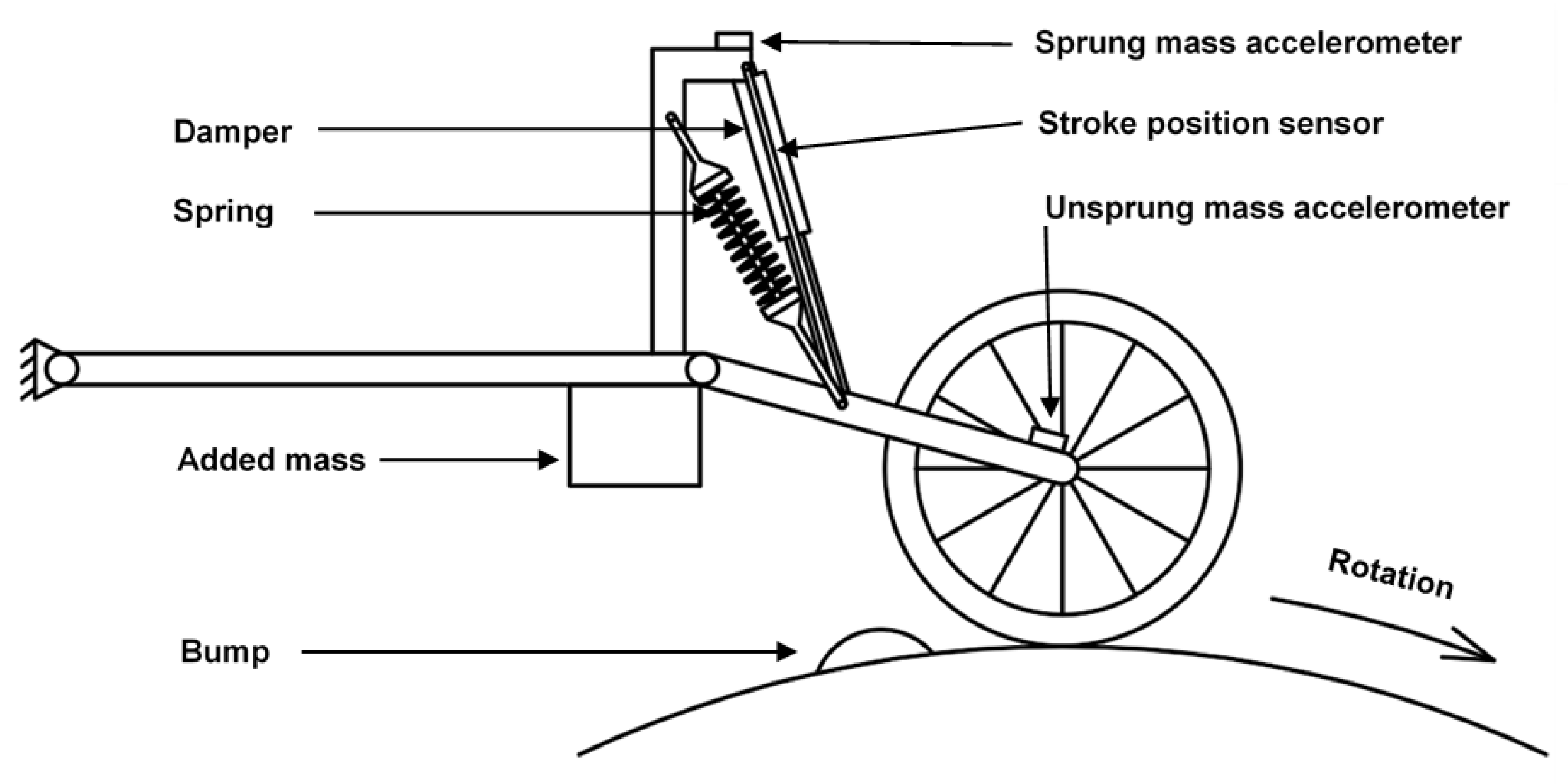
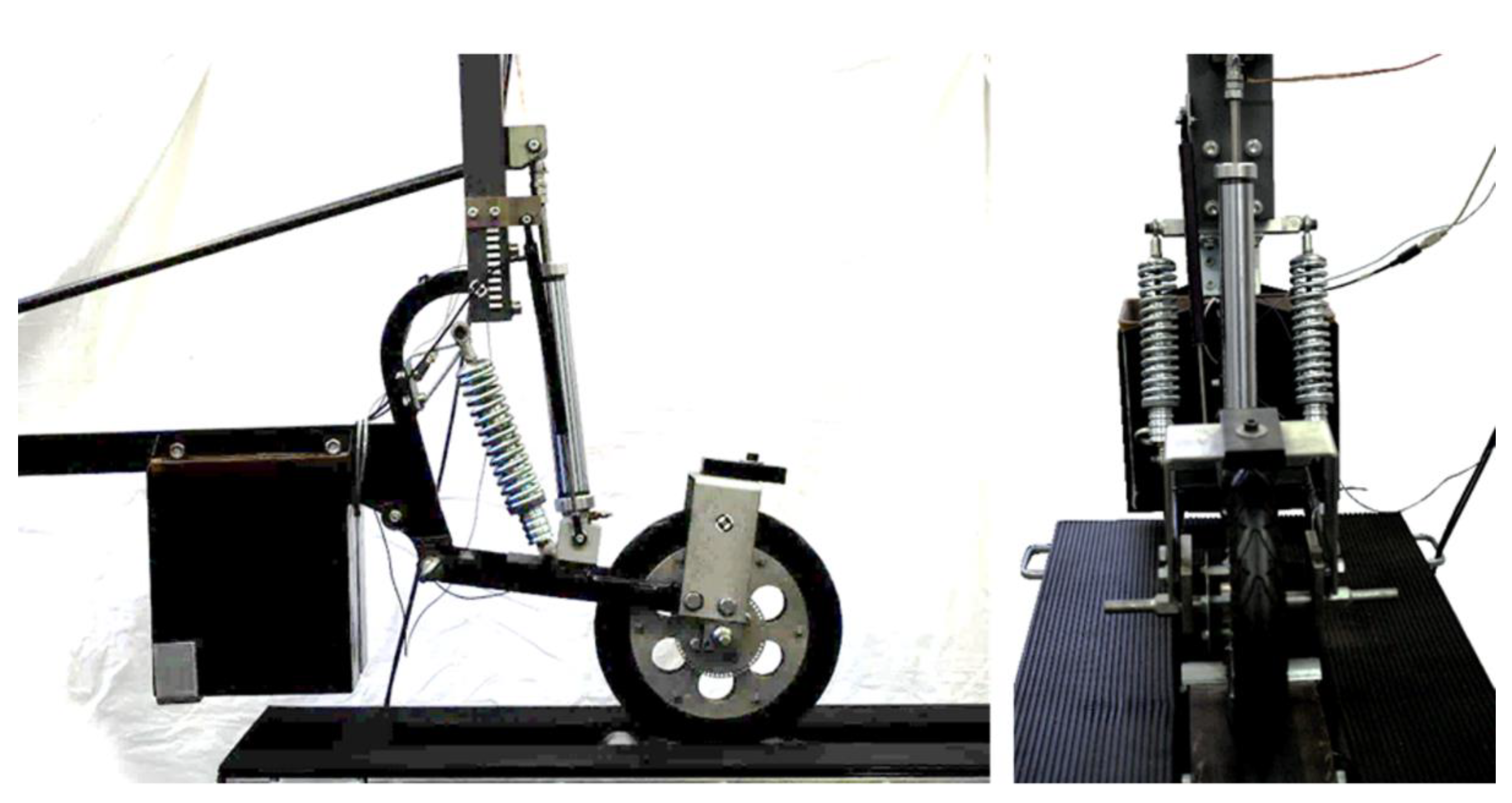
2.1. Experimental Test Rig

The experimental trolley was designed as an equivalent quarter of a car’s suspension for laboratory testing (Figure 1). The modal characteristics correspond with the Skoda Fabia rear suspension. Thus, it is believed to be compatible with other compact hatchback cars as well. The trolley was sprung by two compression springs and was dampened by an MR damper. The damper is our homemade design. Three sensors are located on the test rig: (i) two B&K 4507B piezoelectric accelerometers (the first one on the sprung mass, the second one on the unsprung mass) and (ii) a VLP 15 SA 150 stroke position sensor. The stroke value was derived to obtain a velocity difference between the sprung and unsprung masses.
The trolley sits on a drum with a diameter of 0.8 m (Figure 1). A bump was added to the drum to simulate a bumpy road. The height of the bump at its highest point is 21 mm above the profile of the drum, and its length is 55 mm. The drum is driven by an electro-motor with an adjustable frequency, which allows for the changing of the ride speed in the range of 0–15 m/s. A Hall sensor checked the speed of the drum. The grip (normal force between a road and the wheel) was measured by strain gauges on the drum’s bearing mountings, which were calibrated on the force measurement at the contact. The force and speed signals were acquired in a front-end Dewe-800 at a sampling frequency of 5000 Hz. The layout of the experimental test rig can be seen in Figure 2.
The control system (Figure 3) consists of an Arduino Uno board, which collects the input signals from the sensors and creates the control signal. The control signal goes into the current controller with an overvoltage option. This method allows for the rapid change of electric current on the coil.

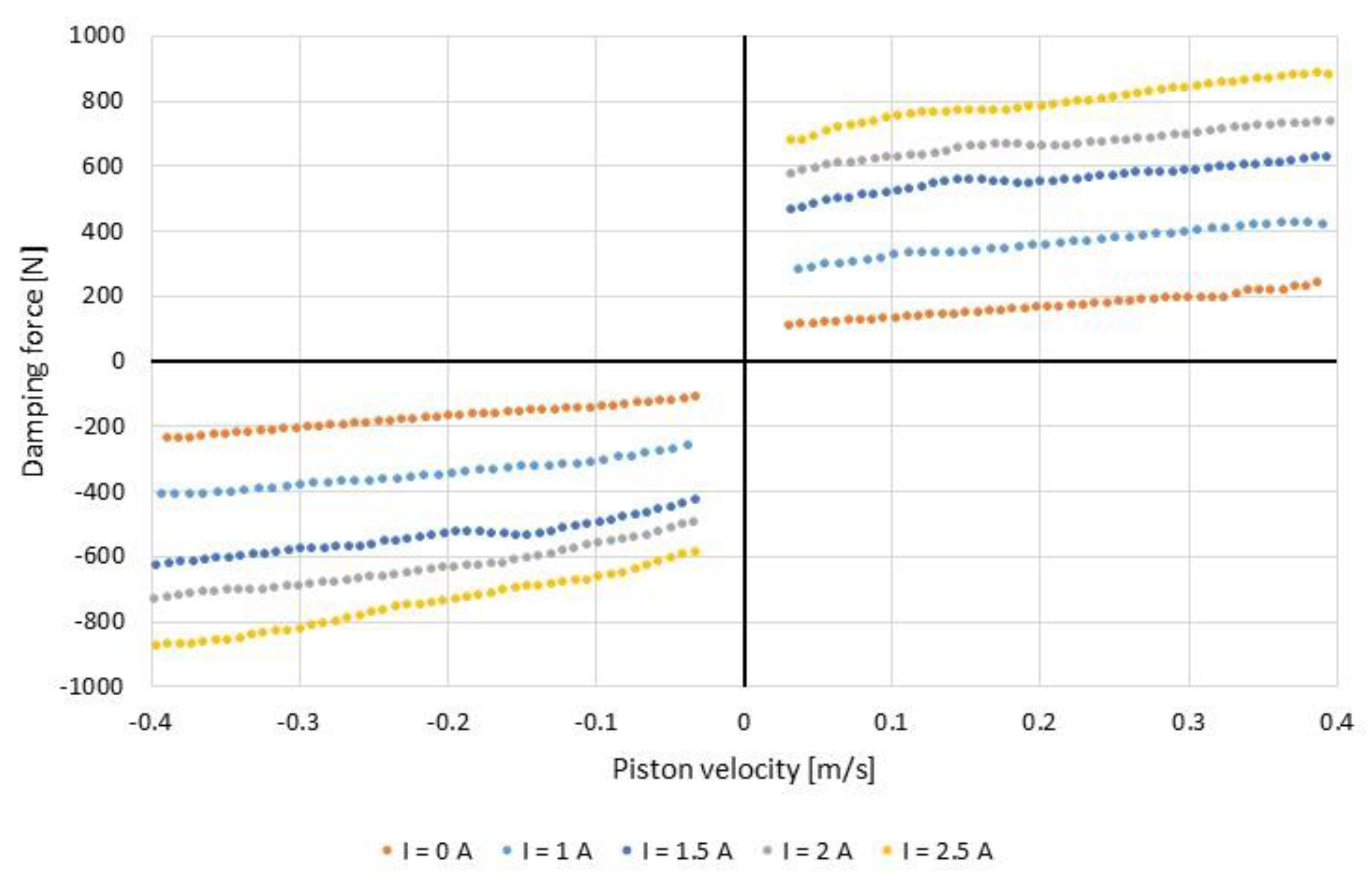
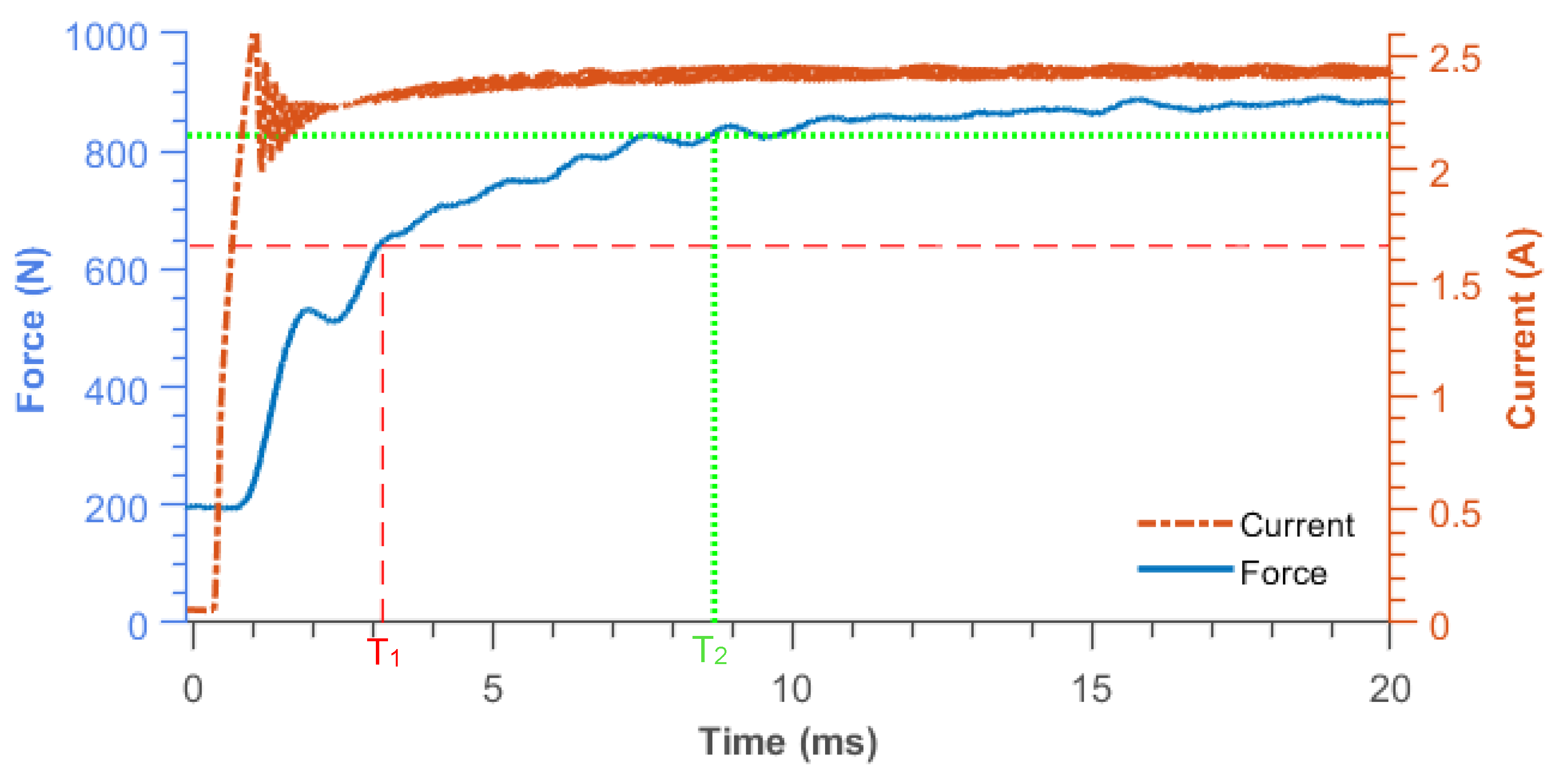
2.2. Magnetorheological Damper

Our designed magnetorheological damper was used. It is the improved version of that published by Strecker et al. [37]. This is a monotube MR damper with a one coil configuration. The magnetic circuit was made of SMC (soft magnetic composite), which suppresses the eddy currents, allowing a short response time to be achieved. The damper has a stroke of 135 mm, and the piston’s diameter is 36 mm. The length of the active zone is 2 × 8 mm, and the gap’s (slit’s) width is 0.65 mm. The damper was filled by MRF-132DG MR fluid produced by LORD Corp., headquartered in Cary, NC, USA.
The most important characteristic of a hydraulic damper is the F–V (Force–velocity) characteristic (Figure 4). The measurement of the damper was conducted on a hydraulic pulsator fabricated by INOVA. The temperature significantly affects the damping force; therefore, it has been maintained between 40 and 50 °C during the F–V measurement. This temperature was also kept during the experiments.
The response time of the damper affects the performance of the semi-active control. The transient characteristics of a real MR damper are quite challenging to describe. This system must be described by a transfer function of a high order. However, the transient behavior is simplified into an exponential function (first-order system with dead time) for our simulations (see Figure 5). In the first-order system, the primary response time (T1) is the time needed to reach 63.2% of the final control value (steady-state) [16], and this was the type of system that was used in the paper. The secondary response time (T2) is the time to reach 95% of the final control value. The response time of our damper was measured with different values of overvoltage, and values of 3 ms and 8.5 ms were obtained as the average values of the primary and secondary response times, respectively. For the simulation, a 2 ms response time with a 1 ms delay (dead time) was selected, as seen in Figure 5.

2.3. Groundhook Algorithm Selection

We selected the Groundhook algorithm for the test because the main goal of the study was to measure the wheel grip. The stability of the grip is the primary goal for improving the vehicle’s handling, and Groundhook-styled algorithms are intended to accomplish that. The basic Groundhook algorithm uses two main inputs: the difference in the velocities of the road and unsprung mass and the difference in the velocities of an unsprung and sprung mass, as shown by Equation (1). The wheel is dampened when it moves in the opposite direction to the (car or trolley’s) body, preventing the wheel from undesirable vibrations.
F G r o u n d h o o k = { b H ( v 2 v 1 ) ,   i f   ( v 2 v 1 ) ( v 1 v 0 ) < 0 b L ( v 2 v 1 ) ,   i f   ( v 2 v 1 ) ( v 1 v 0 ) 0 }
In Equation (1), F is the damping force, bh is the activated state damping coefficient, bL is the non-activated state damping force, v0 is the vertical road surface velocity, v1 is the unsprung mass velocity, and v2 is the sprung mass velocity.
However, the standard algorithm is complicated to use in a real application. Measuring the difference in the road and unsprung mass velocities is usually inconvenient. Therefore, the modified Groundhook algorithm is generally used in these operations. The algorithm removes the tricky part of measuring the mutual velocity of the wheel and the road and replaces it by using the acceleration of the unsprung mass instead, which is much easier to measure. This means that the wheel is dampened when the force from the road pushes the wheel against the spring, preventing the wheel from bouncing when the wheel has enough support from the main body. See Equation (2):
F d a m p e r = { b H ( v 2 v 1 ) ,   i f   a 1 ( v 2 v 1 ) 0 b L ( v 2 v 1 ) ,   i f   a 1 ( v 2 v 1 ) < 0 }
where a1 is the unsprung mass acceleration. All other symbols have the same meaning as in Equation (1).

2.4. Ride Quality Evaluation
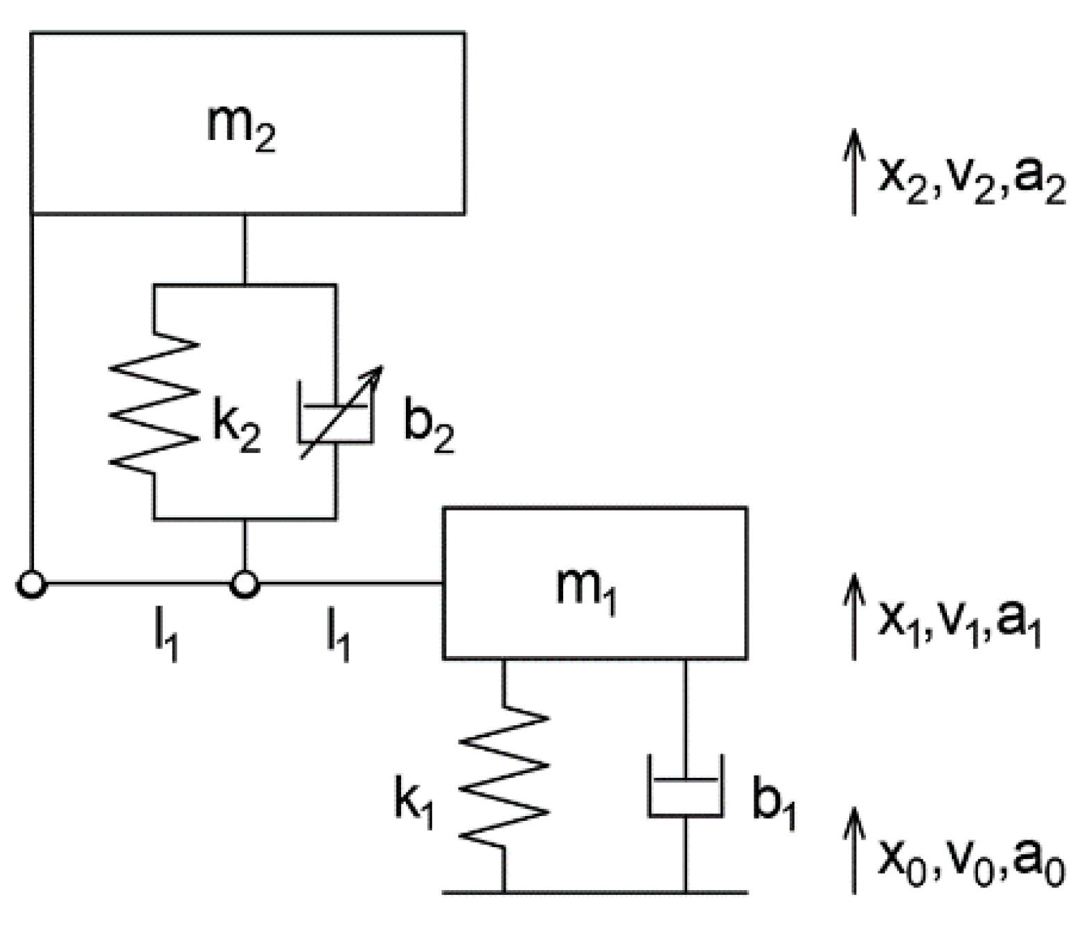
It was decided to use two main criteria to quantify the ride qualities. The first criterium deals with the acceleration of the sprung mass and, therefore, ride comfort. Vibrations are intended to be minimalized to obtain a smoother ride. The relevant variable which describes the number of vibrations is the AC RMS acceleration value in the vertical direction:
a e f = lim T 1 T 0 T a 2 2 ( t )   d t ,
where a2(t) is the acceleration of a sprung mass and T is the measurement time.
In discrete measurements provided by sensors, the comfort level is expressed as the standard deviation of the sprung mass acceleration. While the desired acceleration and its mean value are 0, the equation is:
σ ( a 2 ) = 1 N i = 1 N a 2 ( i ) 2
where a2(i) is the discrete value of acceleration and N is the number of discrete values.
A suspension’s ride safety and handling capability are determined by maintaining a stable wheel adhesion, no matter the external condition. The force between a road and the wheel ought to fluctuate as little as possible. If the force significantly alternates over time (the wheel loses contact in extreme situations), the ability to transfer brake and lateral forces is limited. The suspension quality can be expressed as the standard deviation of the adhesion force:
σ ( F ) = 1 N i = 1 N ( F s t a t F i ) 2
where Fi is the discrete value of adhesion force, and Fstat is the static value of the adhesion force caused by the mass of the trolley.
These parameters were obtained from the sensors mentioned in Section 2.1. The acceleration of the sprung mass values was measured using the piezoelectric accelerometers and the adhesion force values were obtained from the strain gauges. The static force (Fstat) produced by the mass of the trolley and the drum was subtracted from the aggregate force (Fi). In total, the measurements were repeated 3 times.
It is necessary to mention that comparing those parameters is only possible for systems with the same input (road profile, duration, velocity, etc.).

2.5. Dynamic Model

The dynamic model of a one-wheel suspension consists of two masses (Figure 6). One of them (part 1) represents a wheel (unsprung mass), which is connected with a base (element 0) via elastic and dampened connections with no possibility of adjustment, thus representing a tire. The second mass, which symbolizes a car’s body (sprung mass), is connected to the first one via a lever and is sprung by a passive elastic connection (a spring) and is dampened by a controllable damping member (MR shock absorber) connected to the lever as well. This corresponds with the experimental model, where the suspension comprises a trailing arm and passive elastic connection (a spring) with a controllable damping member (MR damper). The road and its bumps are simulated by a movement of the base element (kinematic excitation).
As shown in Figure 6, the body mass (element 2) is hinged to the ground and the suspension (element 1) is hinged to the main body. In reality, both masses perform a rotary motion. However, their rotation is negligible due to the length of their levers. The movements of both masses were simplified into the 1D translational movement.
This system can be described by the following equations:
m 1 x 1 ¨ + b 1 ( x 1 ˙ x 0 ˙ ) + k 1 ( x 1 x 0 ) = m 1 g 0.5   b 2 ( x 2 ˙ 0.5 x 1 ˙ ) 0.5 k 2 ( x 2 0.5 x 1 ) m 2 x 2 ¨ + b 2 ( x 2 ˙ 0.5 x 1 ˙ ) + k 2 ( x 2 0.5 x 1 ) = m 2 g + 0.5 b 2 ( x 2 ˙ 0.5 x 1 ˙ ) + 0.5 k 2 ( x 2 0.5 x 1 )
The system parameters were obtained by a separate measurement, and their values are shown in Table 1. The parameters of the MR dampers were determined in the paragraphs above (see Figure 4).
The system was then programmed in Matlab using a Simulink environment. The simulation parameters were chosen as follows:
  • Method—ode4 (Runge–Kutta);
  • Step size—fixed to 0.0002 s (5000 steps/s)
The simulation time was chosen to allow the model to settle down for 3 s (the initial conditions are impossible to choose correctly; therefore, extra time for stabilization was needed). Then, 4 rotations of the drum were simulated, from which the last 3 rotations were evaluated (the first rotation’s results could have been different due to the trolley’s transition from a stationary to a dynamic regime).

3. Results

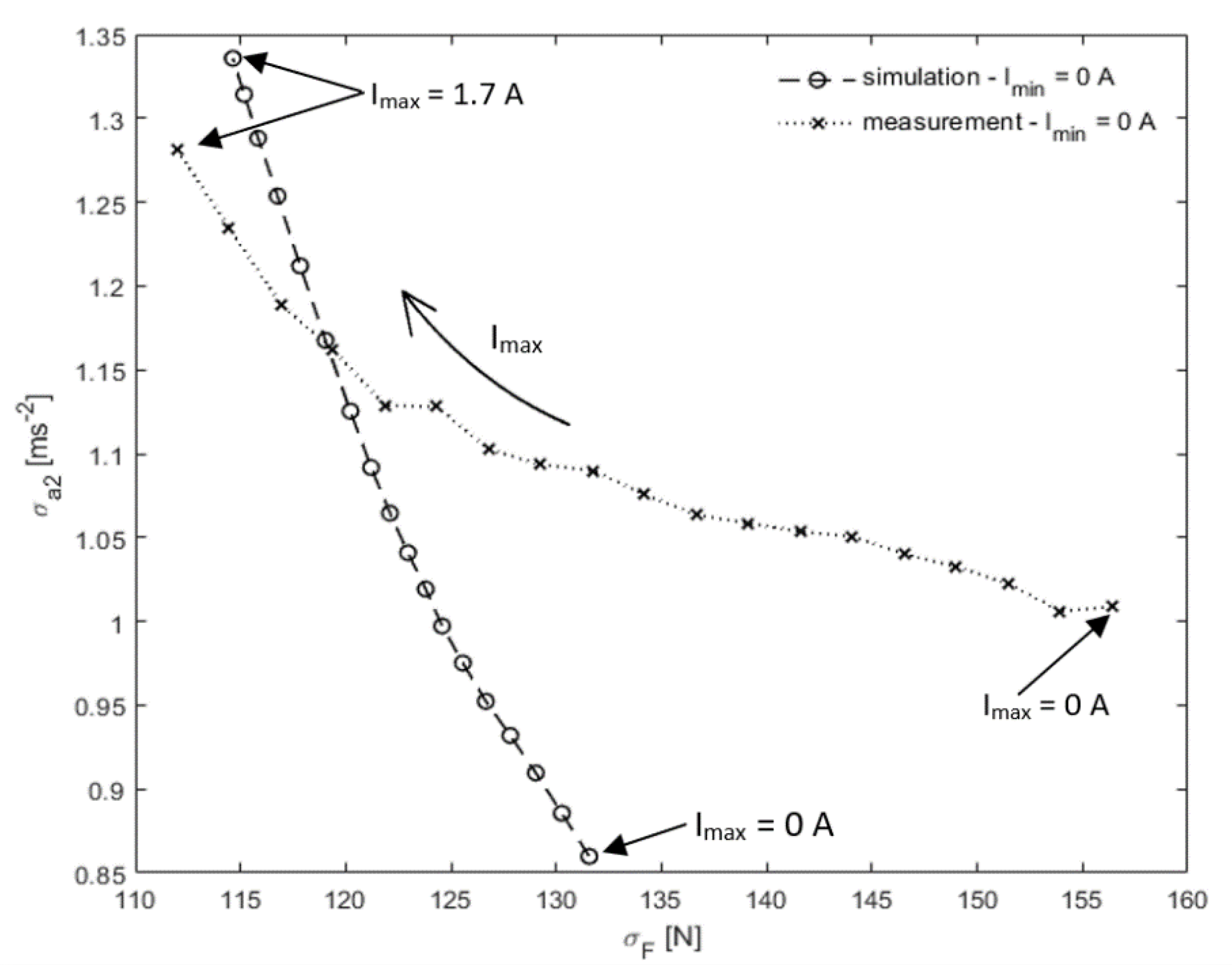
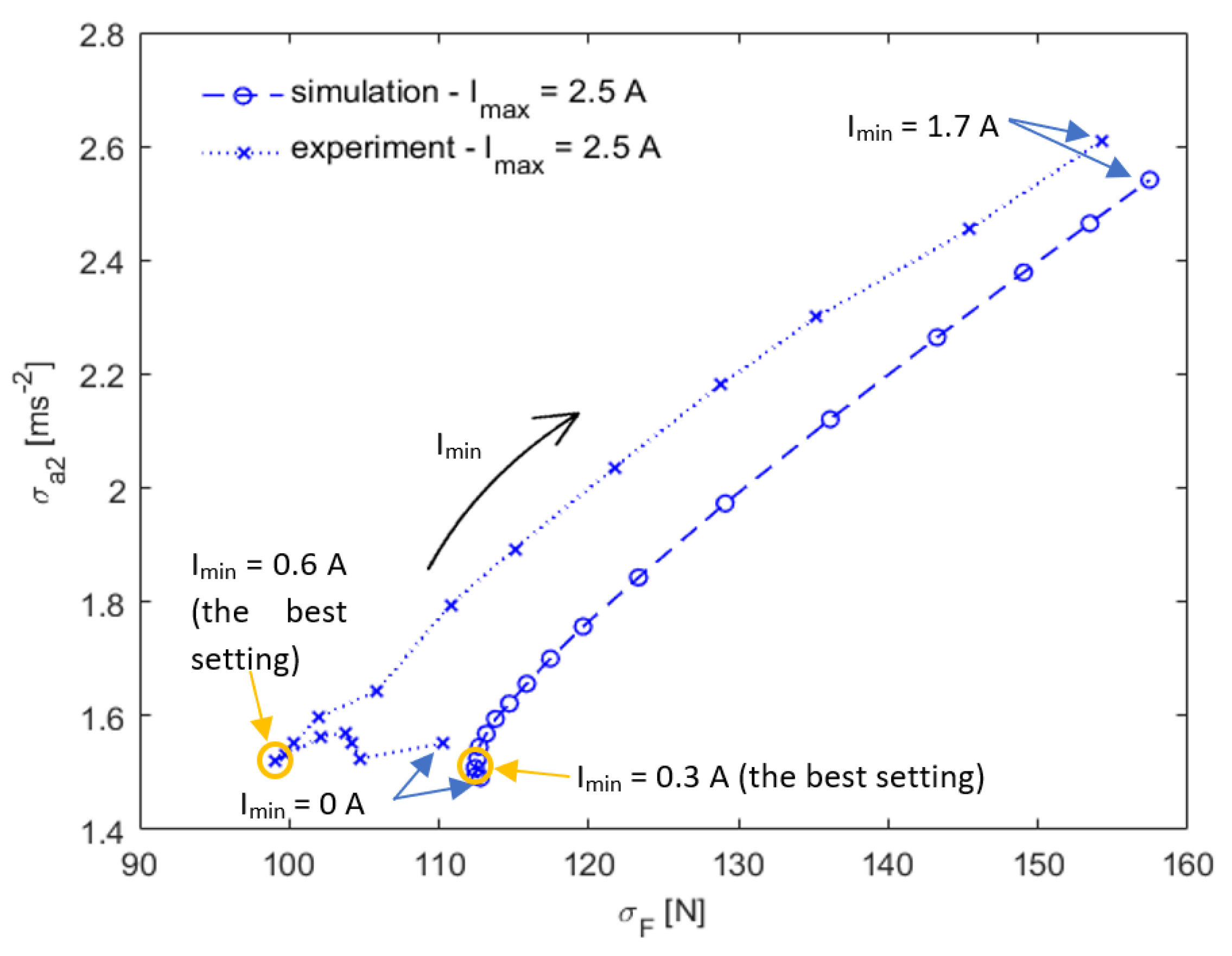
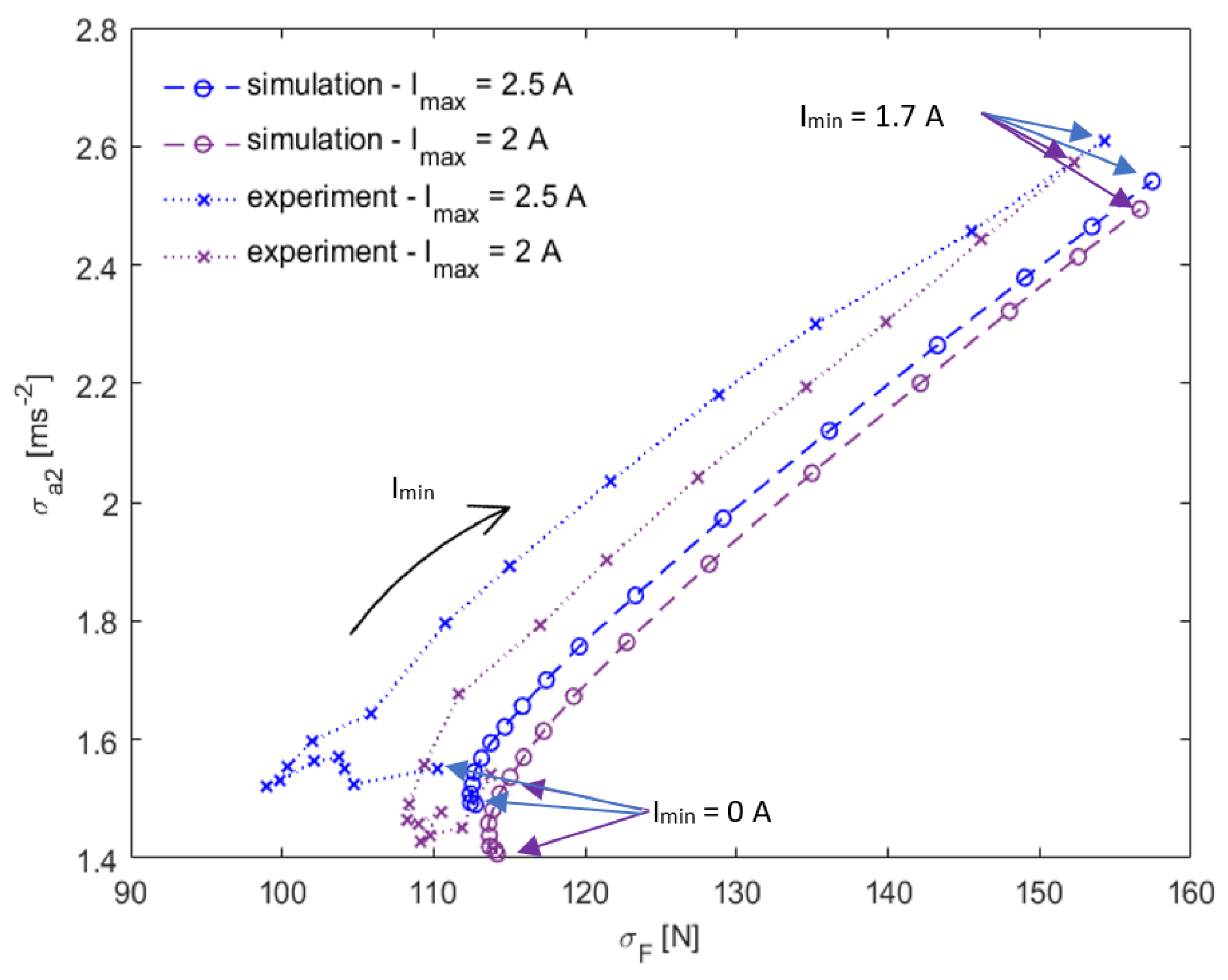
3.1. Comparison of Groundhook Settings

Firstly, the impact of the activated state force on the Groundhook algorithm was examined. The non-activated current (Imin) was set to 0 A, which corresponds to the F–V characteristics shown in Figure 4. The simulations and experiments were conducted with different F–V characteristics, which were defined by the activated current. The activated state current (Imax) was separately and gradually set in 0.1 A increments from 0 A to 2.5 A for each measurement. The results are shown in Figure 7. It can be shown that the comfort steadily decreased as the activated force rose, but on the contrary, the grip increased.
Then, the impact of the non-activated state force was examined (Figure 8). The activated state current (Imax) was set to 2.5 A, and the non-activated current (Imin) was shifted again in 0.1 A steps. The Imin ranged from 0 A to 1.7 A. The simulation and the experiment showed similar trends in results, but strangely enough, the experiments showed better results than the simulations in all measurements. Both the simulation and the experiment proved that the non-activated state current should be higher than 0 A. It was discovered that the non-activated damping level should not be too low. For our damper, the ideal non-activated current was around 0.6 A for the experimental results and 0.3 A for the simulation (see yellow circles in Figure 8). However, the values can vary for different dampers. Below that value, the trend differed. While the grip immediately worsened in the experiment, in the simulation, the grip started to steadily deteriorate. However, it did not evolve more due to the inability to reach a lower damping force.
As seen in the combined results of the activated and non-activated force (Figure 9), the dynamic range should be as high as possible to obtain the best grip possible. This proves Machacek’s theory [12], which claims that the dynamic range of the damper should be as high as possible (at least until the value of 10). However, in our current damper design, it is impossible to reach a dynamic range higher than 8.3 (the maximum achievable dynamic range for Imin = 0.6 A is 2.3) because the ideal non-activated force characteristic is not the lowest one achievable by the damper.
Because the change in the measured parameters is not linearly dependent on the damping level (current), the results created C-shaped curves in a σF−σa figure. Strecker et al. [4] and Poussot-Vasal [34] also simulated these curves. However, in those papers, the damper had a relatively lower damping level compared with ours as well as a smaller damping force, so the C-shapes of their curves were more profound towards the lower damping levels; furthermore, they found the best damping characteristics to lie in the middle of their setting range.

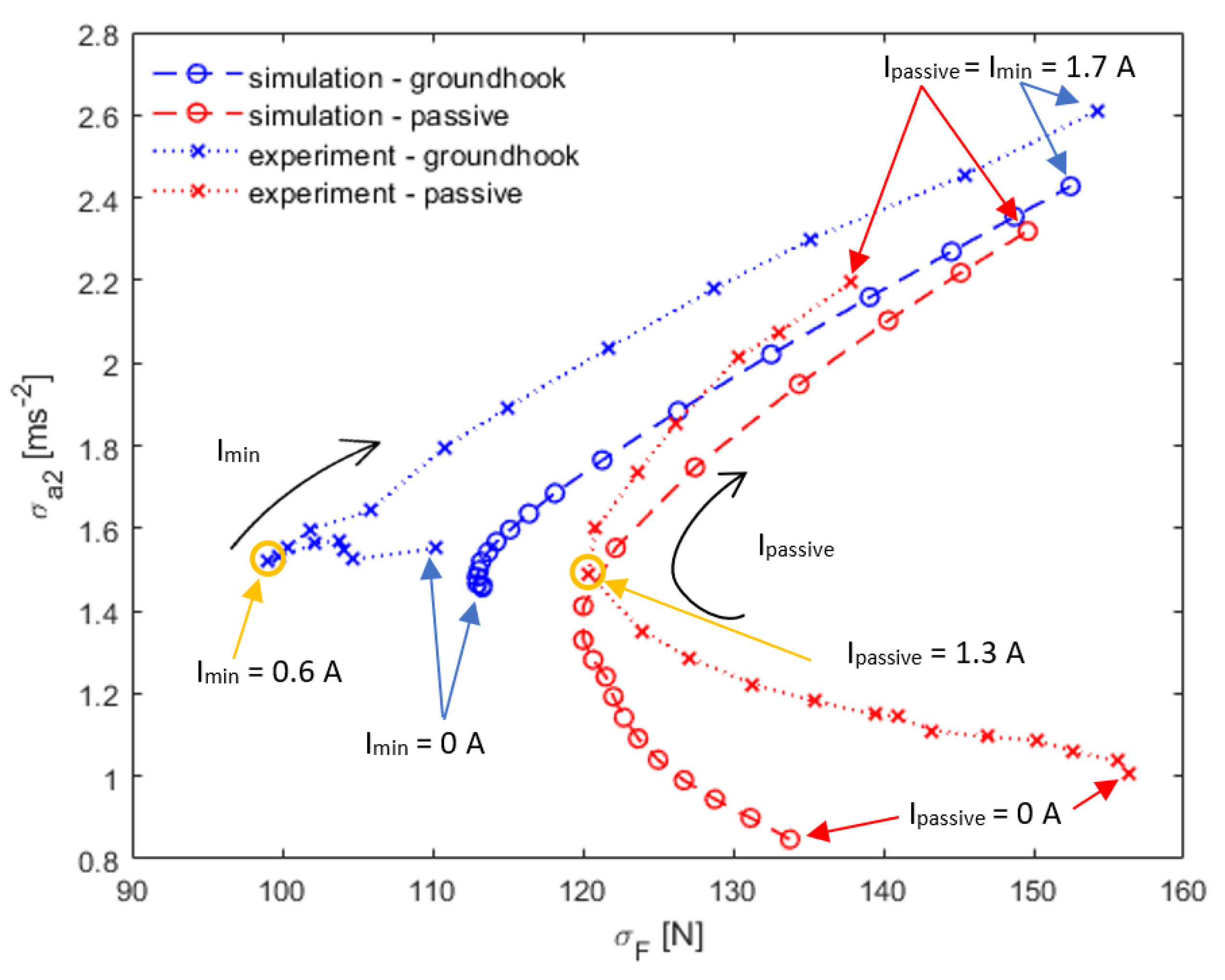
3.2. Comparison of Passive and Semiactive Mode

A passive mode was compared with the most efficient Groundhook algorithm (Figure 10). In the passive mode, it was proven that the smoothest ride had been achieved by a minimalizing a damping force. This can be achieved by minimalizing the current in an MR damper. However, this setup harms the handling properties, which can be improved by increasing the current and the damping force, respectively. In our case, the ideal current for the passive mode was somewhere around Ipassive = 1–1.3 (see the orange point in Figure 10). The simulation showed a similar trend as the measurement, although the real-measurement results were much more widely spread, and the comfort RMS was approximately 10% worse.
Compared with the S/A mode, the passive suspension showed approximately 10% higher adhesion force RMS values in simulations. The Groundhook-controlled damping showed significantly better efficiency in the experiments. The best passive configuration was approximately 30% worse than the best S/A experiment, as seen in Figure 10. The improvement exceeded the improvement of the results in Krauze et al. [36]. However, it must be said that the improvement was not as significant as predicted by Strecker et al. [23]. Overall, it can be assumed that the S/A control should probably shorten the braking distance of the vehicle compared with the passive damper.

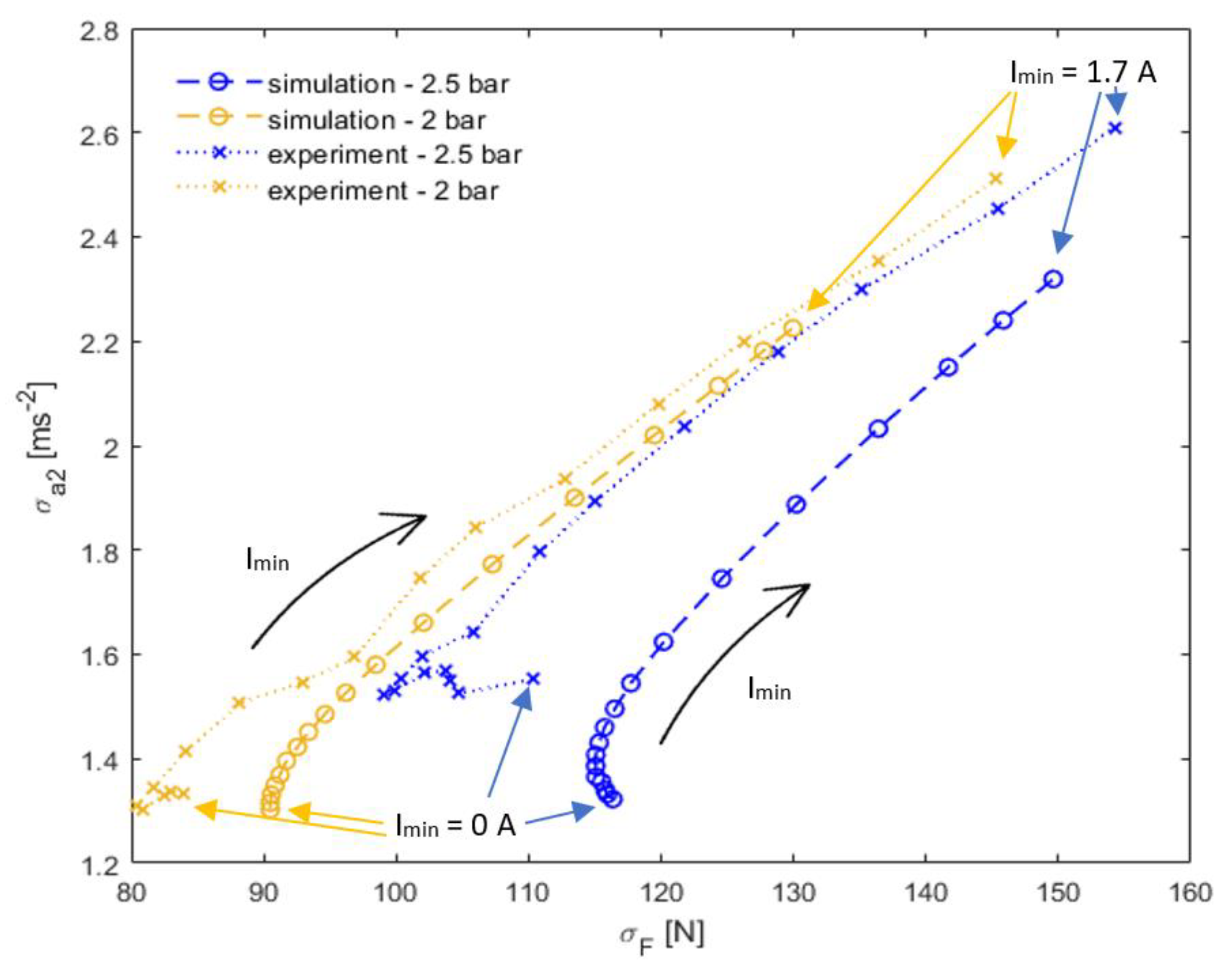
3.3. Effect of Tire Stiffness

The effect of tire pressure and stiffness was also examined (Figure 11). We elected to decrease the tire pressure from 2.5 bar to 2 bar. In the simulation, the tire stiffness was reduced by 20%, and its damping coefficient was increased by 20%. While the tire parameters for 2.5 bar were measured, the parameter change for the 2 bar was only estimated [38]. As can be seen, the lower tire pressure positively affected both parameters, but it must be said that a better grip does not automatically mean better handling. An underinflated tire cannot fully transfer the lateral forces, so the handling capabilities are limited.

4. Discussion

The results show the impact of the Groundhook algorithm on the ability of the suspension to maintain wheel grip with not harming the ride’s comfort. We can see in the figures that the impact could be very significant. The grip was improved by approximately 30%. This is more than we expected from the simulations (approximately 10%). The difference could be made by a slight filtering of the load force signal in the computer, which was necessary due to resonance and the wheel and drum’s imperfections, which occurred during the testing. The simulation was simplified as well. All major parameters are dependent on the damper temperature and the transient behavior is also dependent on the piston velocity and when the current is switching on and off [37]. The F–V characteristics also rely on the stroke position of the damper; these parameters are were hard to simulate and they were not included in the simulation. These factors may explain the shift in results between the simulations and the experiments and is probably the cause of the slightly different trend of results in the test of a very low damping force during the testing of the activated state (Figure 7) and passive damper (Figure 10).
We also did not manage to replicate the C-shaped curves in the σF−σa figures as nicely as Strecker et al. [23] or Poussot-Vassal et al. [34] achieved in their simulations. This mainly happened due to the damper having a relatively high damping level. On the other hand, for the achieving the best grip, the damper should have a slightly higher damping level than now. This allow it to achieve the highest dynamic range as possible. But it harms the ability to cushion the sprung mass from the bumps. Therefore, the precise setting of the off-state damping level appears to be crucial for maintaining the grip and bearable level of comfort.
The effect of a short response time was proven to be crucial. The experimental results show the improvement which Strecker et al. [23] did not achieve. The authors assumed that for a test of similar parameters, the response time should not be higher than 20 ms when using a modified Groundhook algorithm, which seems to be proven. With the unevenly and closely placed potholes mixed with the rugged road surface, the benefits of using a short response damper could be much more significant on a typical road.
The effect of the Groundhook algorithm was also tested by Krauze et al. [36], and the authors claimed that the Groundhook algorithm improved the road handling capability from 8 to 14%. For the first time, this appears to correspond with the experimental results, but it is difficult to tell if the comparison is possible, as completely different criteria was used for the evaluation and the damper information was not provided in the previous study.
The simulated results show the trend according to our results. The improvements were found to be 6%, 15% and 25% by Sulaiman et al. [39], Poussot-Vasal et al. [34], and Yerrawar et al. [40], respectively. Nevertheless, again the evaluation of those results was completely different, and a comparison with those results is not straightforward too.

5. Conclusions

The ability of an S/A suspension controlled by the Groundhook algorithm to maintain grip was simulated and then experimentally proven. To maintain the best grip, it was discovered that:
  • The dynamic range of the damper should be as high as possible
  • The non-activated state should be uniquely set for the vehicle
The ideal setting must be separately set for each vehicle and damper due to the different weight or F–V characteristics, respectively. In our case, the best setting was Imax = 2.5 A and Imin = 0.6 A. The best setting of the Groundhook algorithm was also compared with the passive suspension. It was determined that the ideal passive damper had an approximately 30% higher level of damping compared with a non-activated state of the S/A controlled damper. The S/A control damper achieved an approximately 30% improvement in force fluctuation compared with the best passive mode. It can be assumed that S/A control should probably shorten the braking distance of the vehicle compared with the passive damper.
The tire stiffness also affected results, improving both grip and comfort as the tire pressure decreased. However, this could only be stated in a laboratory on the testing rig. The situation would be different in the real world, as the tire is loaded not only in the radial direction but also by lateral forces.
It can be stated that the Groundhook algorithm with a fast MR damper provides a rapid improvement in handling. However, the trolley does not fully represent the car; thus, it would be appropriate to prove the settings on a car in the future.

Author Contributions

J.Ž.: Measurement, dynamic model, writing; K.Š.: measurement, writing; H.M.: measurement; F.J.: dynamic model; Z.S.: conceptualization, validation; M.K.: supervision and editing. All authors have read and agreed to the published version of the manuscript.

Funding

Grant 7659, “Improving seat comfort by semi-active control of magnetorheological damper” was realized within the project of Quality Internal Grants of the BUT (KInG BUT), Reg. No. CZ.02.2.69/0.0/0.0/19_073/0016948, which was financed from the OP RDE.

Institutional Review Board Statement

Not applicable.

Informed Consent Statement

Not applicable.

Data Availability Statement

The data presented in this study are available on request from the corresponding author.

Conflicts of Interest

The authors declare no conflict of interest. The funders had no role in the design of the study; in the collection, analyses, or interpretation of data; in the writing of the manuscript; or in the decision to publish the results.

References

  1. Jeyasenthil, R.; Yoon, D.; Choi, S.; Kim, G. Robust Semiactive Control of a Half-car Vehicle Suspension System with Magnetorheological Dampers: Quantitative Feedback Theory Approach with Dynamic Decoupler. Int. J. Robust Nonlinear Control 2021, 31, 1418–1435. [Google Scholar] [CrossRef]
  2. LaPlante, J.A.; Larkins, W.T. Semi-Active Shock Absorber Control System. US20040254701, 16 December 2004. [Google Scholar]
  3. Eslaminasab, N.; Golnaraghi, M.F. The Effect of Time Delay of the Semi-Active Dampers on the Performance of On-Off Control Schemes. In Proceedings of the ASME 2007 International Mechanical Engineering Congress and Exposition. Volume 9: Mechanical Systems and Control, Parts A, B, and C, Seattle, WA, USA, 11–15 November 2007; pp. 1911–1918. [Google Scholar]
  4. Bica, I.; Liu, Y.D.; Choi, H.J. Physical Characteristics of Magnetorheological Suspensions and Their Applications. J. Ind. Eng. Chem. 2013, 19, 394–406. [Google Scholar] [CrossRef]
  5. Pisetskiy, S.; Kermani, M. High-Performance Magneto-Rheological Clutches for Direct-Drive Actuation: Design and Development. J. Intell. Mater. Syst. Struct. 2021, 32, 2582–2600. [Google Scholar] [CrossRef] [PubMed]
  6. Li, W.H.; Du, H. Design and Experimental Evaluation of a Magnetorheological Brake. Int. J. Adv. Manuf. Technol. 2003, 21, 508–515. [Google Scholar] [CrossRef]
  7. Zhou, H.; Yao, P.; Xiao, Y.; Fan, K.; Zhang, Z.; Gong, T.; Zhao, L.; Deng, M.; Liu, C.; Ling, P. Tribology International Friction and Wear Maps of Copper Metal Matrix Composites with Different Iron Volume Content. Tribol. Int. 2019, 132, 199–210. [Google Scholar] [CrossRef]
  8. Gołdasz, J.; Sapiński, B. Insight into Magnetorheological Shock Absorbers; Springer: Berlin/Heidelberg, Germany, 2015; ISBN 9783319132334. [Google Scholar]
  9. Kumar, S.; Sehgal, R.; Wani, M.F.; Sharma, M.D. Stabilization and Tribological Properties of Magnetorheological (MR) Fluids: A Review. J. Magn. Magn. Mater. 2021, 538, 168295. [Google Scholar] [CrossRef]
  10. Ashtiani, M.; Hashemabadi, S.H.; Ghaffari, A. A Review on the Magnetorheological Fluid Preparation and Stabilization. J. Magn. Magn. Mater. 2015, 374, 711–715. [Google Scholar] [CrossRef]
  11. Zhu, X.; Jing, X.; Cheng, L. Magnetorheological Fluid Dampers: A Review on Structure Design and Analysis. J. Intell. Mater. Syst. Struct. 2012, 23, 839–873. [Google Scholar] [CrossRef]
  12. Machacek, O.; Kubik, M.; Novák, P. A New Method of Magnetorheological Damper Quality Evaluation. Eng. Mech. 2017, 2017, 594–597. [Google Scholar]
  13. Goldasz, J. Magnetostatic Study of a Dual-Gap MR Valve. In Proceedings of the 2019 20th International Conference on Research and Education in Mechatronics (REM), Wels, Austria, 23–24 May 2019. [Google Scholar] [CrossRef]
  14. Abd Fatah, A.Y.; Mazlan, S.A.; Koga, T.; Zamzuri, H.; Imaduddin, F. Design of Magnetorheological Valve Using Serpentine Flux Path Method. Int. J. Appl. Electromagn. Mech. 2016, 50, 29–44. [Google Scholar] [CrossRef]
  15. Koo, J.-H.; Goncalves, F.D.; Ahmadian, M. A Comprehensive Analysis of the Response Time of MR Dampers. Smart Mater. Struct. 2006, 15, 351–358. [Google Scholar] [CrossRef]
  16. Guan, X.; Guo, P.; Ou, J. Study of the Response Time of MR Dampers. In Proceedings of the Second International Conference on Smart Materials and Nanotechnology in Engineering, Weihai, China, 8–11 July 2009; p. 74930U. [Google Scholar] [CrossRef]
  17. Zhang, H.H.; Xu, H.P.; Liao, C.R.; Deng, Z.X. Dynamic Response of Magnetorheological Fluid Damper for Automotive Suspension and the Influence by Long-Time Standing-Still. Appl. Mech. Mater. 2011, 105–107, 1689–1692. [Google Scholar] [CrossRef]
  18. Strecker, Z.; Jeniš, F.; Kubík, M.; Macháček, O.; Choi, S.B. Novel Approaches to the Design of an Ultra-Fast Magnetorheological Valve for Semi-Active Control. Materials 2021, 14, 2500. [Google Scholar] [CrossRef] [PubMed]
  19. Kubík, M.; Goldasz, J. Multiphysics Model of an MR Damper Including Magnetic Hysteresis. Shock Vib. 2019, 2019, 3246915. [Google Scholar] [CrossRef] [Green Version]
  20. Kubík, M.; Šebesta, K.; Strecker, Z.; Jeniš, F.; Goldasz, J.; Mazůrek, I. Hydrodynamic Response Time of Magnetorheological Fluid in Valve Mode: Model and Experimental Verification. Smart Mater. Struct. 2021, 30, 125020. [Google Scholar] [CrossRef]
  21. Kubík, M.; Válek, J.; Žáček, J.; Jeniš, F.; Borin, D.; Strecker, Z.; Mazůrek, I. Transient Response of Magnetorheological Fluid on Rapid Change of Magnetic Field in Shear Mode. Sci. Rep. 2022, 12, 10612. [Google Scholar] [CrossRef]
  22. Goncalves, F.D.; Ahmadian, M.; Carlson, J.D. Investigating the Magnetorheological Effect at High Flow Velocities. Smart Mater. Struct. 2006, 15, 75–85. [Google Scholar] [CrossRef]
  23. Strecker, Z.; Mazůrek, I.; Roupec, J.; Klapka, M. Influence of MR Damper Response Time on Semiactive Suspension Control Efficiency. Meccanica 2015, 50, 1949–1959. [Google Scholar] [CrossRef]
  24. Balamurugan, L.; Jancirani, J. An Investigation on Semi-Active Suspension Damper and Control Strategies for Vehicle Ride Comfort and Road Holding. Proc. Inst. Mech. Eng. Part I J. Syst. Control Eng. 2012, 226, 1119–1129. [Google Scholar] [CrossRef]
  25. Karnopp, D.; Crosby, M.J.; Harwood, R.A. Vibration Control Using Semi-Active Force Generators. ASME Pap. 1973, 619–626. [Google Scholar] [CrossRef] [Green Version]
  26. Soliman, A.M.A.; Kaldas, M.M.S. Semi-Active Suspension Systems from Research to Mass-Market—A Review. J. Low Freq. Noise Vib. Act. Control 2021, 40, 1005–1023. [Google Scholar] [CrossRef] [Green Version]
  27. Hong, K.S.; Sohn, H.C.; Hedrick, J.K. Modified Skyhook Control of Semi-Active Suspensions: A New Model, Gain Scheduling, and Hardware-in-the-Loop Tuning. J. Dyn. Syst. Meas. Control. Trans. ASME 2002, 124, 158–167. [Google Scholar] [CrossRef] [Green Version]
  28. Nguyen, Q.H.; Choi, S.B.; Park, Y.G. An Analytical Approach to Optimally Design of Electrorheological Fluid Damper for Vehicle Suspension System. Meccanica 2012, 47, 1633–1647. [Google Scholar] [CrossRef]
  29. Ata, W.G.; Salem, A.M. Semi-Active Control of Tracked Vehicle Suspension Incorporating Magnetorheological Dampers. Veh. Syst. Dyn. 2017, 55, 626–647. [Google Scholar] [CrossRef]
  30. Oh, J.S.; Jeon, K.; Kim, G.W.; Choi, S.B. Dynamic Analysis of Semi-Active MR Suspension System Considering Response Time and Damping Force Curve. J. Intell. Mater. Syst. Struct. 2021, 32, 1462–1472. [Google Scholar] [CrossRef]
  31. Nie, J.; Yang, Y.; Jiang, T.; Zhang, H. Passive Skyhook Suspension Reduction for Improvement of Ride Comfort in an Off-Road Vehicle. IEEE Access 2019, 7, 150710–150719. [Google Scholar] [CrossRef]
  32. Krauze, P. Skyhook Control of Front and Rear Magnetorheological Vehicle Suspension; Springer: Berlin/Heidelberg, Germany, 2011. [Google Scholar]
  33. Valášek, M.; Kortüm, W.; Šika, Z.; Magdolen, L.; Vaculín, O. Development of Semi-Active Road-Friendly Truck Suspensions. Control Eng. Pract. 1998, 6, 735–744. [Google Scholar] [CrossRef]
  34. Poussot-Vassal, C.; Spelta, C.; Sename, O.; Savaresi, S.M.; Dugard, L. Survey and Performance Evaluation on Some Automotive Semi-Active Suspension Control Methods: A Comparative Study on a Single-Corner Model. Annu. Rev. Control 2012, 36, 148–160. [Google Scholar] [CrossRef] [Green Version]
  35. Ahmadian, M.; Goncalves, F.D.; Sandu, C. An Experimental Analysis of Suitability of Various Semiactive Control Methods for Magneto Rheological Vehicle Suspensions. Smart Struct. Mater. 2005 Damping Isol. 2005, 5760, 208–216. [Google Scholar] [CrossRef]
  36. Krauze, P.; Kasprzyk, J.; Kozyra, A.; Rzepecki, J. Experimental Analysis of Vibration Control Algorithms Applied for an Off-Road Vehicle with Magnetorheological Dampers. J. Low Freq. Noise Vib. Act. Control 2018, 37, 619–639. [Google Scholar] [CrossRef] [Green Version]
  37. Strecker, Z.; Roupec, J.; Mazurek, I.; Machacek, O.; Kubik, M.; Klapka, M. Design of Magnetorheological Damper with Short Time Response. J. Intell. Mater. Syst. Struct. 2015, 26, 1951–1958. [Google Scholar] [CrossRef]
  38. Cường, Đ.M.; Hong, Z.S.; Hùng, Đ.V.; Ngọc, N.T. Study on the Vertical Stiffness and Damping Coefficient of Tractor Tire Using Semi-Empirical Model. Hue Univ. J. Sci. Agric. Rural Dev. 2013, 83. [Google Scholar] [CrossRef]
  39. Sulaiman, S.; Samin, P.M.; Hishamuddin, J.; Abd Rahman, R.; Burhaumudin, M.S. Groundhook Control of Semi-Active Suspension for Heavy Vehicle. Int. J. Reasearch Eng. Technol. 2012, 1, 146–152. [Google Scholar]
  40. Yerrawar, R.N.; Arakerimath, R.R. Performance Assessment and Control Policies for Semiactive Suspension Using SIMSCAPE. In Proceedings of the 2016 International Conference on Automatic Control and Dynamic Optimization Techniques (ICACDOT), Pune, India, 9–10 September 2016; pp. 1163–1168. [Google Scholar] [CrossRef]
Figure 1. Experimental apparatus.
Actuators 11 00354 g001
Figure 2. The trolley on the drum.
Actuators 11 00354 g002
Figure 3. Control system.
Actuators 11 00354 g003
Figure 4. F–V characteristics of the damper.
Actuators 11 00354 g004
Figure 5. Response time of the damper (red line—T1, green line—T2).
Actuators 11 00354 g005
Figure 6. Numerical model.
Actuators 11 00354 g006
Figure 7. Groundhook setting—activated state setting (changing activated state current—Imax).
Actuators 11 00354 g007
Figure 8. Groundhook setting—non-activated state setting Imin (circled items indicate best setting according to the RMS of the adhesion force).
Actuators 11 00354 g008
Figure 9. Combined results of the Groundhook algorithms.
Actuators 11 00354 g009
Figure 10. Comparison of the Groundhook algorithm and passive mode (circles indicate the best RMS adhesion force).
Actuators 11 00354 g010
Figure 11. Tire pressure comparison.
Actuators 11 00354 g011
Table 1. Model parameters.
VariableMeaningModel Setting
m1Unsprung mass6.7 kg
m2Sprung mass42.2 kg
k1Tire stiffness50,190 N m−1
k2Main spring stiffness7380 N m−1
b1Tire damping coefficient100 Ns m−1
b2MR damper coefficientFigure 4
Publisher’s Note: MDPI stays neutral with regard to jurisdictional claims in published maps and institutional affiliations.

