Article

Improvement of Adaptive Motion Performance in a Flexible Actuator, Based on Electrically Induced Deformation

1
School of Mechanical Engineering, Hangzhou Dianzi University, Hangzhou 310018, China
2
Wenzhou Institute of Hangzhou Dianzi University, Wenzhou 325013, China
3
Mstar Technologies, Inc., Hangzhou 310012, China
*
Author to whom correspondence should be addressed.
Actuators 2022, 11(11), 338; https://doi.org/10.3390/act11110338
Submission received: 24 October 2022 / Revised: 17 November 2022 / Accepted: 18 November 2022 / Published: 21 November 2022
(This article belongs to the Section Actuator Materials)

Abstract

:
An actuator built with flexible material has the advantage of smaller size and can withstand certain collisions better than actuators with rigid material. This paper proposes a crawling actuator model driven by dielectric elastomer (DE), which uses the electrically induced deformation of the DE membrane to drive the motion of the actuator. When the dielectric elastomer in the actuator is at higher voltage, the DE material produces higher deformation, and the deformation is transmitted to the ground through the friction foot thus driving the motion of the actuator. An interpolation fitting estimation algorithm (IFEA) was constructed based on the relevant material properties and principles. The pre-stretch length of the DE membrane was determined and verified through experiment; the verified results showed that the actuator has better driving performance when the membrane pre-stretching ratio is equal to 3. The crawling actuator can achieve a speed of about 50 mm/s at 4 kv and can reach 11 mm/s when loaded with four times its weight. The new crawling actuator achieved an excellent turning ability of 8.2°/s at 60% duty cycle and 32 Hz frequency. Compared with other types of crawling actuators, the actuator presented in this work has better load capacity and crawling performance.

1. Introduction

Crawling insects have a more agile speed and small size, they can carry objects many times their own body weight, and because of their relatively small size and weight, they can bear the risk of falling from high altitude [1,2]. Current bionic actuator models have the disadvantages of low weight and slow crawling compared with insects [3,4,5,6,7,8,9,10,11,12,13], and because the core components of conventional drives are made of rigid materials, they are more sensitive to collisions or drops. Compared with the traditional actuator, which has limited freedom of motion and cannot realize continuous deformation, the use of flexible material as the power source can reduce the size of the actuator by virtue of its characteristics with or without the limitation of motor. The core of the traditional actuator is a rigid part, which makes it more sensitive to collision or dropping. If a relatively violent impact occurs accidentally, it may cause irreversible damage to the actuator’s structure. In this regard, flexible actuators have a significant advantage because the flexible material can absorb most of the energy generated by the drop or collision, depending on its characteristics. In summary, the flexible actuator has great development prospects [14,15,16,17,18,19].
Significant progress has been made in the design and construction of bio-integrated and flexible wearable devices using software materials, but improvements in the field of actuators have not been very encouraging [20,21,22,23,24,25,26]. Currently, hard materials are still used for the main material composition of the actuator. In contrast, the driving part of the flexible actuator is composed of flexible materials, mainstream among which are shape memory polymer, hydrogel, dielectric elastomer, etc., [27,28,29]. Among these, elastomer is a prominent representative of such materials. Compared with other flexible materials, dielectric elastomer has the characteristics of high flexibility, good compatibility, simple structure, good environmental adaptability, fast response speed, convenient control, etc. [30]. These advantages lead to broad research prospects for flexible actuators constructed of dielectric elastomer, in scientific research, medical treatment, rescue, military, and other fields.
In current practice, several dielectric elastomer films are used, as shown in Table 1. By comparison of the parameters, it can be seen that acrylic dielectric elastomer has great advantages in terms of maximum driving strain, energy conversion efficiency, mass energy density, and other aspects. The representative material for acrylic dielectric elastomer was 3M VHB. This material is easy to obtain and has excellent mechanical properties. It is one of the ideal dielectric elastomer materials.
It therefore represents a high-load crawler actuator, which adopts dielectric elastomer as its power source and has the functions of high load, fast crawling, and steerability. The housing of the actuator is flat in shape, and the whole DE membrane is mounted inside a square frame, the square exterior is connected by two pillars, one end of the pillar equipped with a spring, and the spring force generated by the spring is used to balance the force generated by the DE membrane. When powered, the DE membrane generates Maxwell force to counteract part of the elastic force, thus unsettling the balance formerly maintained with the spring, the actuator extends forward for a certain distance, and the film and spring reach balance in the new position.

2. Materials and Methods

2.1. Materials

Among many dielectric elastomer materials, 3m’s VHB4910 acrylic tape was chosen as the experimental material, having high deformation capacity, high energy density per unit condition, and high dielectric constant. Moreover, the material is a daily consumable, so it is easy to obtain and moderately priced. MG Chemicals carbon conductive grease 846-80G was chosen as the material for the flexible electrodes. To attain the high voltage required for the experiment, a model 0 high voltage power supply from Haiwo Power Technology Co., Ltd. (Changsha, China) was used in this work, which has a maximum voltage output of 10 kv and can provide a variety of signals such as constant wave, triangle wave, sine wave, square wave, etc. The power supply employed a 3.7–12 V lithium battery, with relatively high safety. The displacement sensor was a BL-100NZ laser displacement sensor with an accuracy of 0.075 mm, and the pressure sensor was a LANRIN AUMI type with measurement accuracy of 1 g and a range of 1 kg. Both the displacement sensor and the pressure sensor were connected to the PC host computer via a data cable to collect data in real time.

2.2. Fabrication

For the fabrication of the DE actuator, a four-track stretching machine was firstly designed, the stretching mechanism composed of 3D-printed components as shown in Figure 1a; the stretching mechanism can perform isometric pre-stretching of acrylic membrane of minimum 3 cm × 3 cm up to 5 × 5 times, and the mechanism can also perform unequal-axis pre-stretching to suit different situations. The DE membrane was fixed to the fixture after being stretched. At this point, in order to facilitate the subsequent processing, it was necessary to cut the next suitable size on the membrane. For this reason, a 3D-printing frame was employed and the square cut from acrylic board. Because the stretched film was still viscous, it attached well to the acrylic sheet. The acrylic frame was fixed in the DE membrane, conductive carbon paste was applied on both sides of the membrane to leave a gap of 4–5 mm. After the end of the application, the fiber strip was attached and the DE membrane was cut from the acrylic frame. Finally, as shown in Figure 1b,c, the ends of the membrane were 3D-printed long strips with two protruding cylindrical snaps to hold the DE membrane inside the housing. A spring on the outside of the housing was included to provide an external force. Its function was to provide restoring force for the membrane. A Form2 light curing 3D printer was employed to fabricate the shell of the crawling actuator, which was made of Wenext 8200 resin.
Finally, the friction foot was fabricated. As shown in Figure 1d, the unidirectional friction foot in this experiment used paper clips as the material, which were bent into a V shape with an appropriate angle, then glued to the base of the actuator. The effect of the one-way friction foot largely depends on the angle between the friction foot and the ground. The friction feet were fixed at different angles (every five degrees as a measuring range), and the force-measuring device applied to determine the force required to pull the object. Finally, it was found that the minimum force was required when the angle of the friction foot was 45 degrees, so we selected the 45° angle for the subsequent experiment.
After the fabrication, the power-on experiment was conducted, as shown in Figure 1e, and the elongation of the actuator was ∆L at a voltage of 4 kv.

3. Results and Discussion

3.1. Theoretical Modeling and Simulation

In the process of theoretical modeling, because the individual width of the rigid fibers is one-eighth of that of the dielectric elastomer membrane, the effect on the deformation of the DE membrane is relatively small. The sum of the overall mass of the rigid fibers does not exceed 0.6 g. Therefore, its effect on the deformation of the dielectric elastomer membrane can be ignored in the theoretical model. 
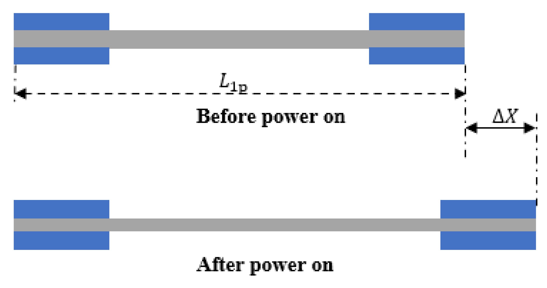
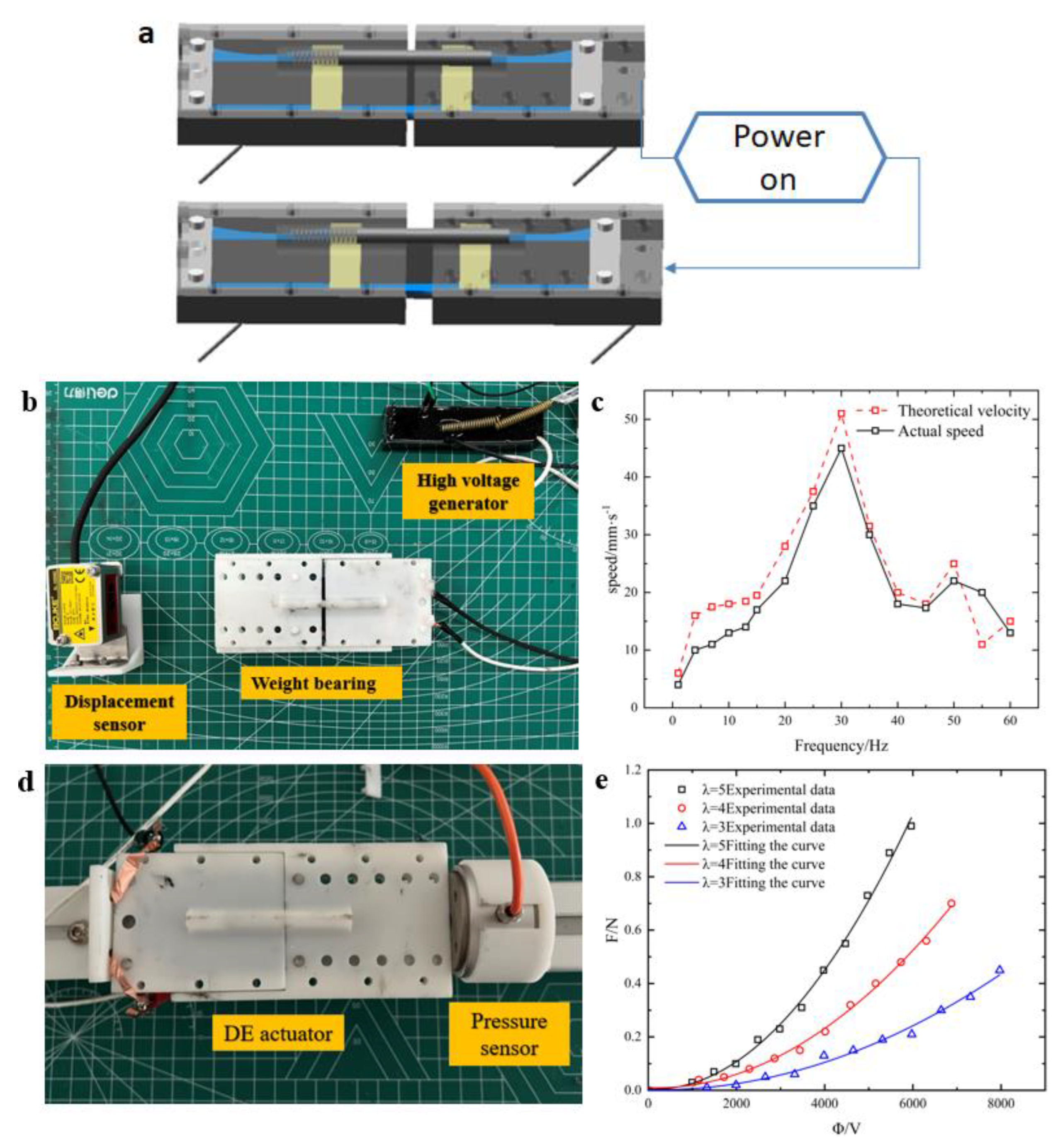
Figure 2 shows a sketch of the dielectric elastomer actuator, where the upper part shows the resting state of the actuator and the lower part shows the actuated state after the actuator is energized. In the stationary state, the overall actuator displacement is nil because the restoring force of the spring for the membrane is equal to the contraction force of the membrane.
After being energized, the top and bottom of the dielectric elastomer membrane undergo deformation due to the voltage. The change in width of the membrane can be simplified to nil because of the support of the PMMA fibers. Due to the incompressibility of the DE membrane, the tensile ratio of the membrane in the length direction η 1 and the displacement Δ L of the film can be expressed by the following function:   η 1 = Δ L / η 1 p L 1 + 1 . Since the dielectric elastomer membrane is a soft material, the fluid model can be introduced to describe the effect of adhesion on the material. Assuming that the deformation of the membrane conforms to the ideal model, the electrostatic energy of the DE membrane is expressed as follows: W 1 = D 2 / 2 ε η 1 2 η 2 2 . In the next calculation, the electric field strength ( E = ϕ / H ) after electrification can be used to replace the potential displacement, and the free energy density of the dielectric elastomer can be expressed as a function of η i , ζ i (i = 1, 2):
W d e ( η 1 , η 2 , ζ 1 , ζ 2 , E ) = μ 2 ( η 1 2 + η 2 2 + η 1 2 η 2 2 3 ) 1 2 ε E 2 η 1 2 η 2 2 + μ 2 ( η 1 2 ζ 1 2 + η 2 2 ζ 2 2 + η 1 2 ζ 1 2 η 2 2 ζ 2 2 3 )
Here, the total volume of the dielectric elastomer is multiplied by the free energy density to obtain the overall potential energy of the membrane U de = V × W de The overall potential energy of the entire membrane includes both the potential energy of the DE membrane and the external spring potential energy, which can be expressed as the spring potential energy with displacement x in the equation U s = kx 2 / 2 . The relationship with ι can be obtained through the shape variable x generated by the DE membrane, so l can be expressed as a function about l = x / l + 1 . Define the Lagrange of the system as:
L ( x , x ˙ , ρ , E ) = E t ( x ˙ ) U t ( x ) U d e ( x , ρ , E )
To simplify the calculation, this paper uses the Rayleigh function to represent the Newtonian fluid damping D ( ρ ) = λ ρ 2 V / 2 , with Equation (1) for three parameters x ,   x ˙ ,   ρ , respectively, to find the partial derivative. We finally obtain:
d 2 x d t 2 + g ( x , ρ , ι 1 p , ι 2 p ) = 0
Equation (3) is the core equation of the dielectric elastomer actuator, and the relationship between the elongation x of the dielectric elastomer actuator, the voltage U applied to the dielectric elastomer membrane, and the time t can be calculated by software such as CLION.
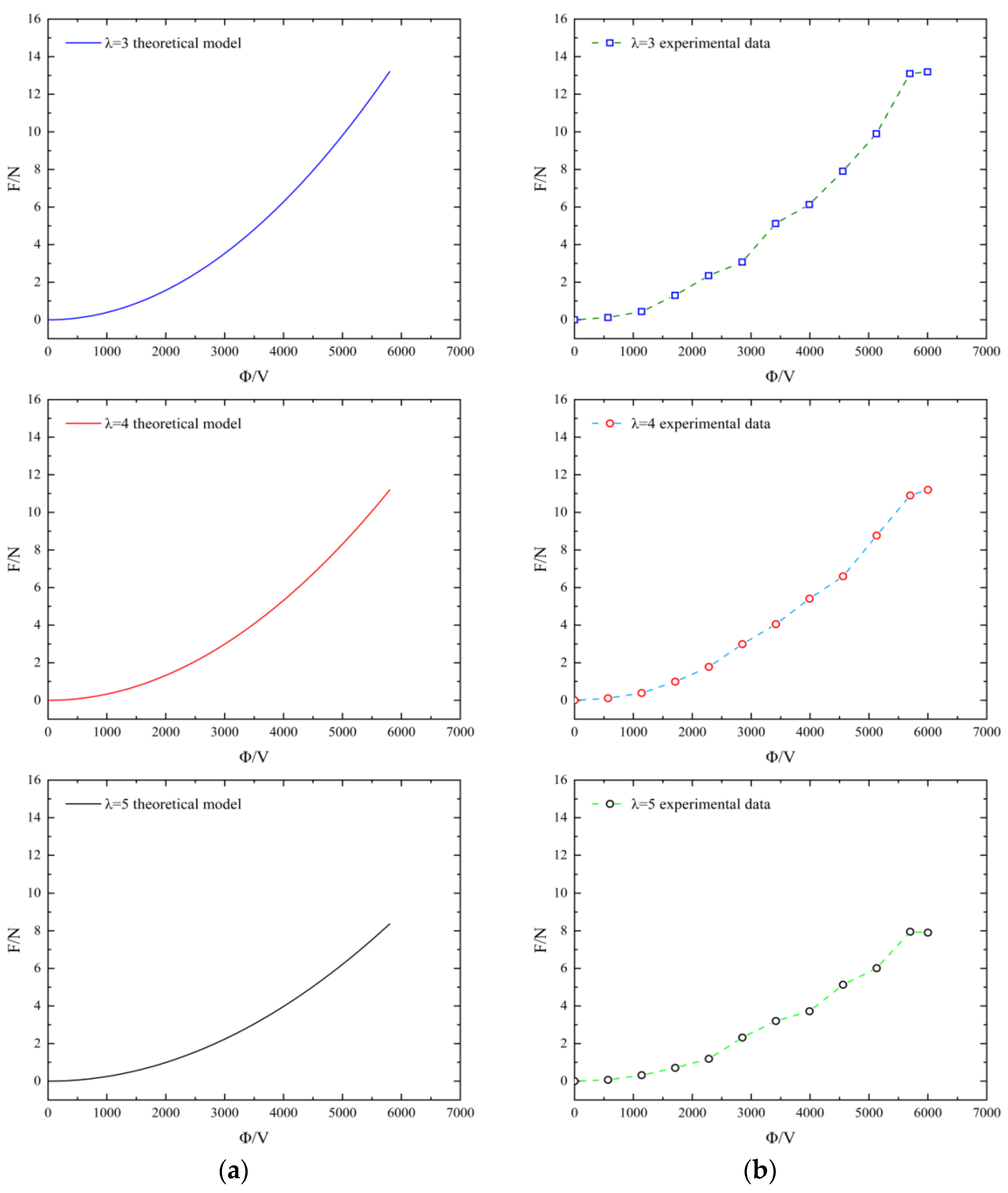
A new interpolation fit estimation algorithm (IFEA) was constructed, with the focus of the algorithm clustered around a cubic difference fit and the calculation of elongation at suitable voltages. For these two problems, the algorithm in this paper mainly uses two for loops, one of which is applied to perform multiple fitting calculations and the other to estimate the elongation at different voltages in units of 1 V. After the estimation was completed, the predicted data were stored. The stored data were then fitted using the regression function. The final fitting function pseudo-code is shown in Algorithm 1. The results after the operation are shown in Figure 3a.
Algorithm 1: IFEA algorithm based on cyclic domain adaptation
InputThe voltage value U in the target, the length, width, and height data of the membrane L 1 L 2 L 3 ,
OutputEstimated value of displacement
ForCalculate the volume V and free energy W of the membrane
V L 1 L 2 L 3
W de W 1 + W 2
Calculate damping
D ( ρ ) 1 2 λ ρ 2 V
Calculate the l function
l x L + 1
Estimation of the output of the displacement x
Add random factor
d ρ dt = 1 φ σ ( l 2 ρ 3 + l 2 ρ )
x Function   Results
End for
ForMultiple difference fitting of the calculated parameters
p ( x ) = a 0 + a 1 x + + a m x m
  IfThe square root of x i is not equal to the smallest
Continue
  End if
End for
In order to determine the effect of different longitudinal (direction of DE membrane motion) pre-stretching on elongation, this paper designed several experiments under different pre-stretching conditions, with the experimental group using a pre-stretching rate of λ = 3 and the control group using stretching rates of λ = 4 and 5.
Figure 3 shows the predicted and experimental results compared under different longitudinal stretching and voltages. The data show that the experimental results and the simulated results basically match, and from Figure 3b it can be seen that the smaller the stretching rate, the better was its elongation performance under the same voltage. Therefore, we choose the tensile rate λ = 3 for the subsequent experiments.
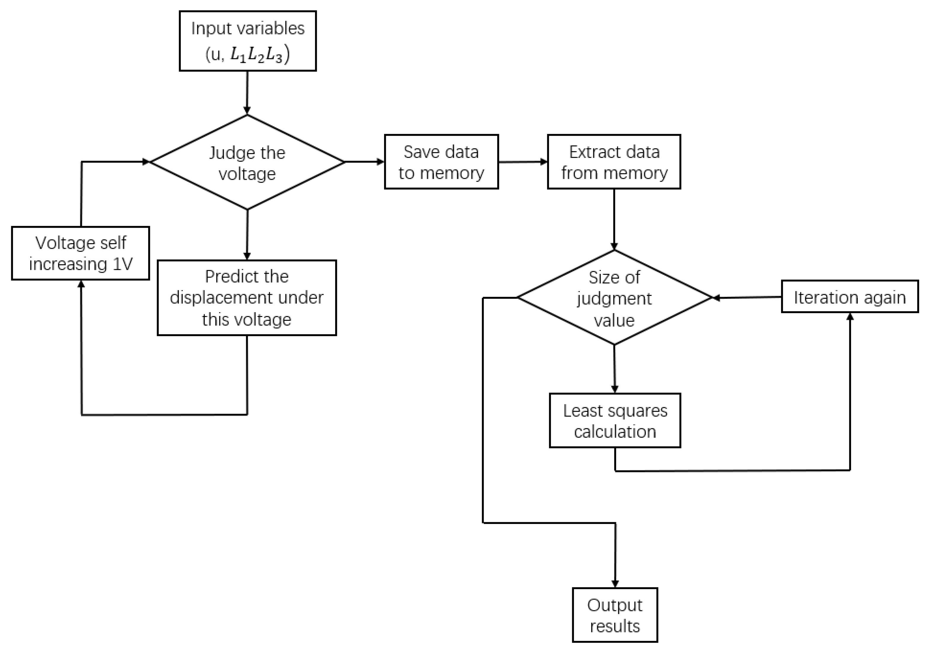
As shown in Figure 4, the algorithm uses the loop twice to solve the function. The first calculation was carried out by converting the DE membrane formulae derived in the article into computer language and then predicting the elongation of the membrane. First, data were input for the length, width, height, and voltage of the film. The volume of the film and the corresponding free energy were calculated. The displacement under the corresponding voltage was obtained by substituting the above data into Formula (3). Because the DE membrane was handmade, interferencefrom uncertain factors was likely, so the IFEA introduces the concept of random factors. The expression of random factors can more accurately simulate the elongation of the film under the interference of external factors. During the calculation, the program opens up a memory space in which the calculated data is temporarily stored.
The second loop is for solving the first result using least squares. The least squares method is a mathematical optimization technique. The theoretical formula adopted by the function is:
i = 1 n ( p ( x i ) y i ) 2 = min
Assume
S ( a 0 , a 1 , , a m ) = i = 1 n ( a 0 + a 1 x + + a m x m y i ) 2 = min
Then
S ( a 0 , a 1 , , a m ) a j = i = 1 n ( a 0 + a 1 x + + a m x m y i ) x i j = 0
By sorting the equations, we can obtain the least square fitting polynomial:
p ( x ) = a 0 + a 1 x + + a m x m
The min in formula (4) is the value that the program needs to judge. If the calculated value is less than or equal to min, the program will judge that the calculation result is correct, and the judged value is the value output by the program. When the second loop starts to calculate, the data stored in the memory space is accessed.
From Figure 3a, we can see that the result predicted by the program is a quadratic fitting curve. The simulation indicates that the actuator will have better performance when the film pre-stretching ratio is 3.

3.2. Crawling Performance

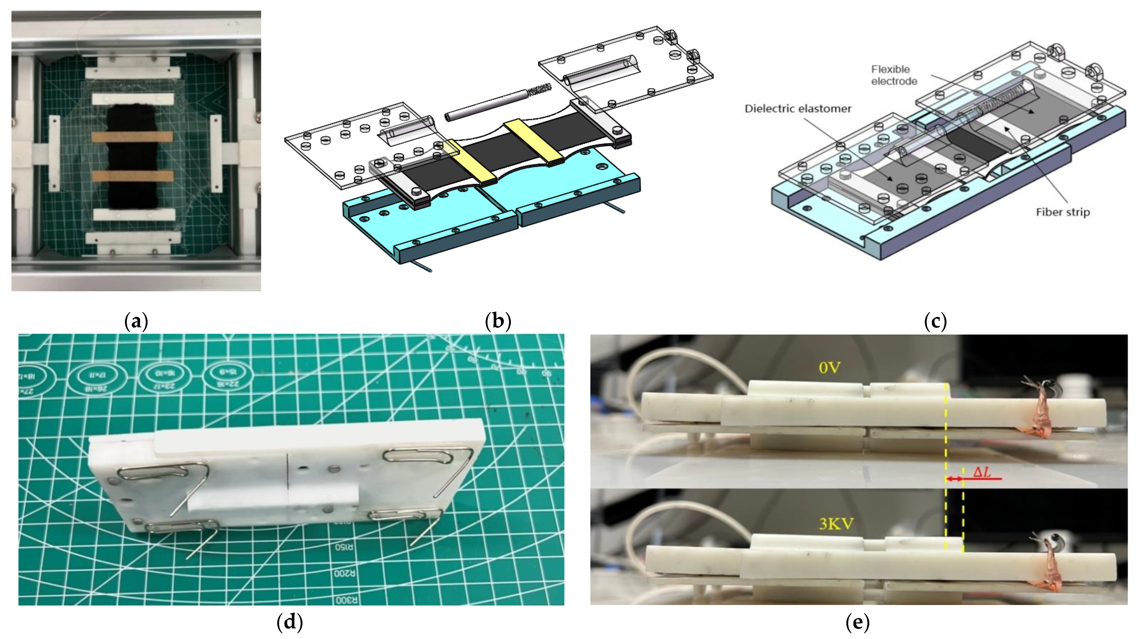
For the crawling actuator, its displacement within the specified time is an important indicator to measure the crawl performance. There are many factors that affect the moving speed of the actuator, principally the size, frequency, and duty cycle of the voltage. Therefore, this section tests the impact of these three factors on the performance of the crawling actuator. As shown in Figure 5a, the DE membrane of the crawling actuator produces regular stretching deformation under the action of periodic voltage, and its deformation is transmitted to the ground through one-way friction feet, so that the crawling actuator can travel along the direction of stretching.
In this part of the study, the square wave was used as the input voltage, with the duty cycle selected as 50%. In order to prevent the breakdown of the DE membrane caused by high voltage, which can lead to significant deformation of the membrane, the voltage selected for this experiment was 4 kv. After applying periodic square wave voltage to the crawling actuator, due to the existence of unidirectional friction feet, the elongation of the DE membrane is converted into the driving force of the actuator. After displacement in a time period is completed, the theoretical crawling speed of the actuator is the displacement that the actuator advances multiplied by the voltage frequency in the period.
The experimental platform is shown in Figure 5b. The crawling actuator was placed on a smooth board with a laser displacement sensor on the left side of the board to measure the displacement of the actuator within the specified time. The time was divided the time by the speed of the actuator, and the average value was calculated.
As shown in Figure 5d, indicating the actual crawling speed of the actuator, the actual crawling speed was lower than the theoretical speed, the reason being that crawling involved friction loss and friction contact of the foot with the plate, and failed to convert fully the power provided by the actuator into forward force. In addition, the deviation between the theoretical speed and the actual speed of the actuator was larger at these points than when the frequency is high. The reason may be that in the larger frequency the elongation of the actuator was relatively small, so the performance of the one-way friction foot better played its role. When the elongation of the actuator at low frequency is large, the one-way friction foot may slip, so the difference between the theoretical and actual values at low frequency is greater than that at high frequencies.
In addition to the elongation at different voltages, the size of the driving force generated by the DE actuator is also an important indicator of a good or bad actuator. Figure 5e shows the relationship between voltage and driving force for different lateral pre-stretch cases. After processing the data, it was found that the relationship between voltage and driving force is similar to that between voltage and displacement, where the driving force increases as the voltage loaded on the DE membrane increases, until after the voltage exceeds a certain limit value, the membrane is broken down and the driving force drops to zero. The experiment shows that the driving force of the actuator is the maximum resistance that the actuator can accept when moving forward. When the resistance of the actuator is less than its driving force, the actuator can move forward smoothly.
Unlike in the displacement test, the direction of the folds appearing in the driving force test was perpendicular to direction of movement of the DE membrane. The experimental data show that when the transverse pre-stretching rate became larger in the appropriate range, the performance of the actuator force not only improved, but we can see from the table below that a larger pre-stretching rate can increase the DE membrane resistance value and the membrane withstood higher voltage without being broken through. The membrane can withstand higher voltages without breakdown, but accordingly, the actuator force generated at the same voltage will be smaller.
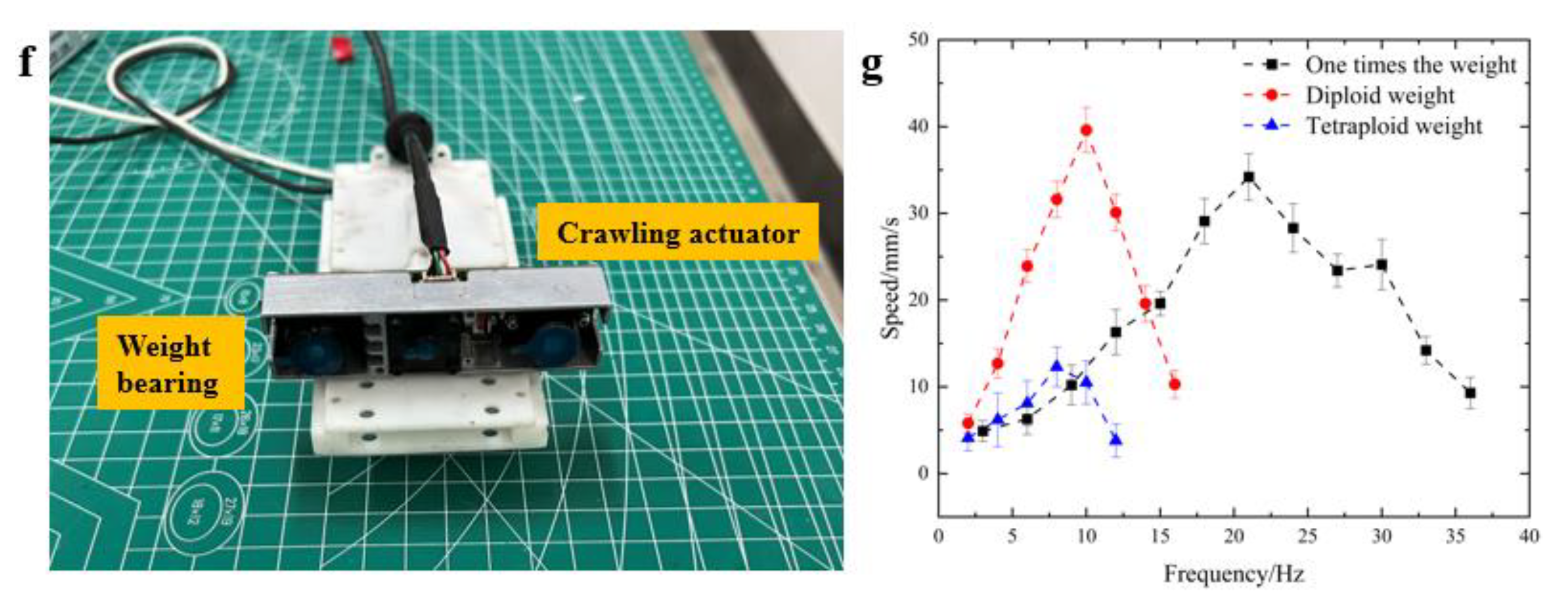
An important task of the actuator is to withstand the load, which is one of the important conditions to verify whether the actuator can meet the tasks of engineering. Therefore, the load experiment is also an important test. We added objects of different weights on top of the actuator, as shown in Figure 5f. The objects were designed to simulate the usage scenarios that the actuator may be used in, and brought the total weight of the objects to about once, twice, and four times the overall weight of the actuator, respectively. Sensors were then employed to measure the distance travelled by the crawling actuator under each load. A graph was plotted from the data, as shown in Figure 5g, for the different loads of the crawling actuator versus frequency.
The figure indicates the frequency corresponding to the maximum speed of the crawling actuator was different when the load was different, and the change rule is that the greater the load of the actuator, the smaller the frequency corresponding to the maximum speed. It also shows that the maximum crawl speed of the actuator under different loads was different; with the increase in load, the maximum speed of the actuator first increased and then decreased. The reason may be that when the load was small, the friction force on the friction foot was not fully converted into driving power to move forward, so when the load increased the grip of the friction foot was enhanced, and the actuator moved with a corresponding increase in speed; but when the load of the actuator exceeded the optimal value, the friction force between the friction foot and the contact surface increased to affect the forward motion, and the speed of the actuator dropped accordingly. In addition, the actuator described in this paper used a simple one-way friction foot made of a paper clip. When the total weight exceeded the stiffness of the paper clip itself, the paper clip was likely to bend, affecting the overall crawling performance of the actuator. A new one-way friction foot was fabricated by 3D printing, but this friction foot increased the contact area on the bottom compared with the paper-clip friction foot. Therefore, the crawling performance of the actuator was reduced, so the experiment finally used a one-way friction foot made of a paper clip as the support foot of the actuator.

3.3. Actuator Motion Improvement

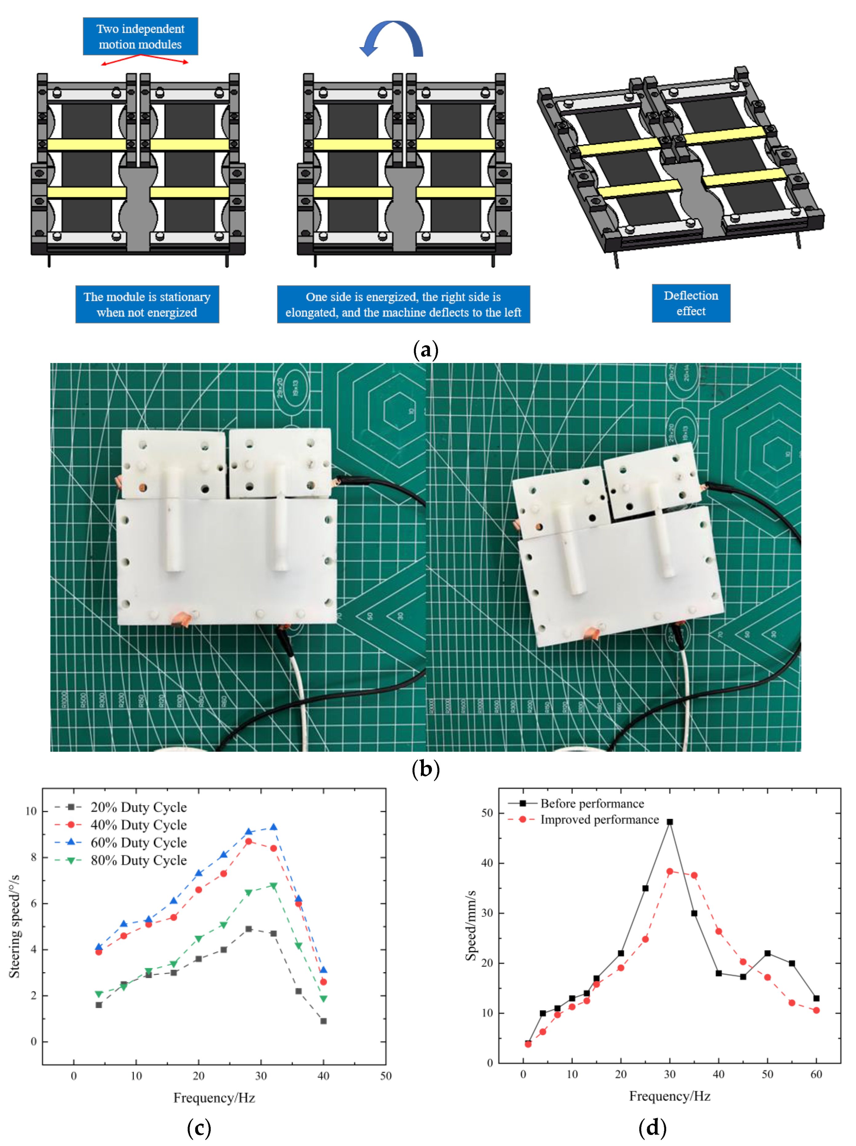
The soft-body actuator was designed in combination, as shown in Figure 6a, the left and right side of the device is a DE actuator. When crawling, drive power on one side of actuator to produce the reciprocating motion does not occur on the other side, so that speed difference is generated between the left and right side of the actuator, and the actuator is deflected back to the non-energized side.
Figure 6b shows the actuator turning diagram; for measurement of the crawling actuator’s turning performance, the principal means is to pass a quantitative square-wave voltage and measure the angle of the crawling actuator turning in a specified time. Therefore, in this experiment, a 4 kv square wave was applied, where the high-value voltage was 4 kv, the low-value voltage 0, and the duration of both high and low values was 2 s. The actuator was allowed to turn 90°, and the time required for that turn was measured. Four sets of data were collected and averaged, and the turning speed was finally calculated.
After improving the crawling actuator and adding the steering function, the two independent actuators had a certain impact on the crawling ability of the actuator, so it was necessary to test the crawling performance of the actuator. The experimental results are shown in Figure 6c. It can be seen from the figure that the influence of increasing duty cycle on cornering performance was nonlinear within the effective frequency range, where 60% of the duty cycle had a better effect.
It was necessary to test the crawling performance of the actuator in an experiment, the results of which are shown in Figure 6d. This research showed that the frequency relative to the maximum speed of the improved actuator changed because the dielectric elastomer membrane changed, thus driving the overall change of the device, and the corresponding frequency also changed. At the same time, because the two sides of the DE membrane were handmade, slight differences are inevitable. Despite the parallel wire design, because of the difference in the tutor DE membrane under the same voltage to produce the elongation, the actuator does not crawl along a perfectly straight line, leading to a slight reduction in crawl performance. Because of the existence of the steering function, the actuator is much more flexible, so the slight decrease in performance is acceptable.

3.4. Fatigue Test of DE Membrane

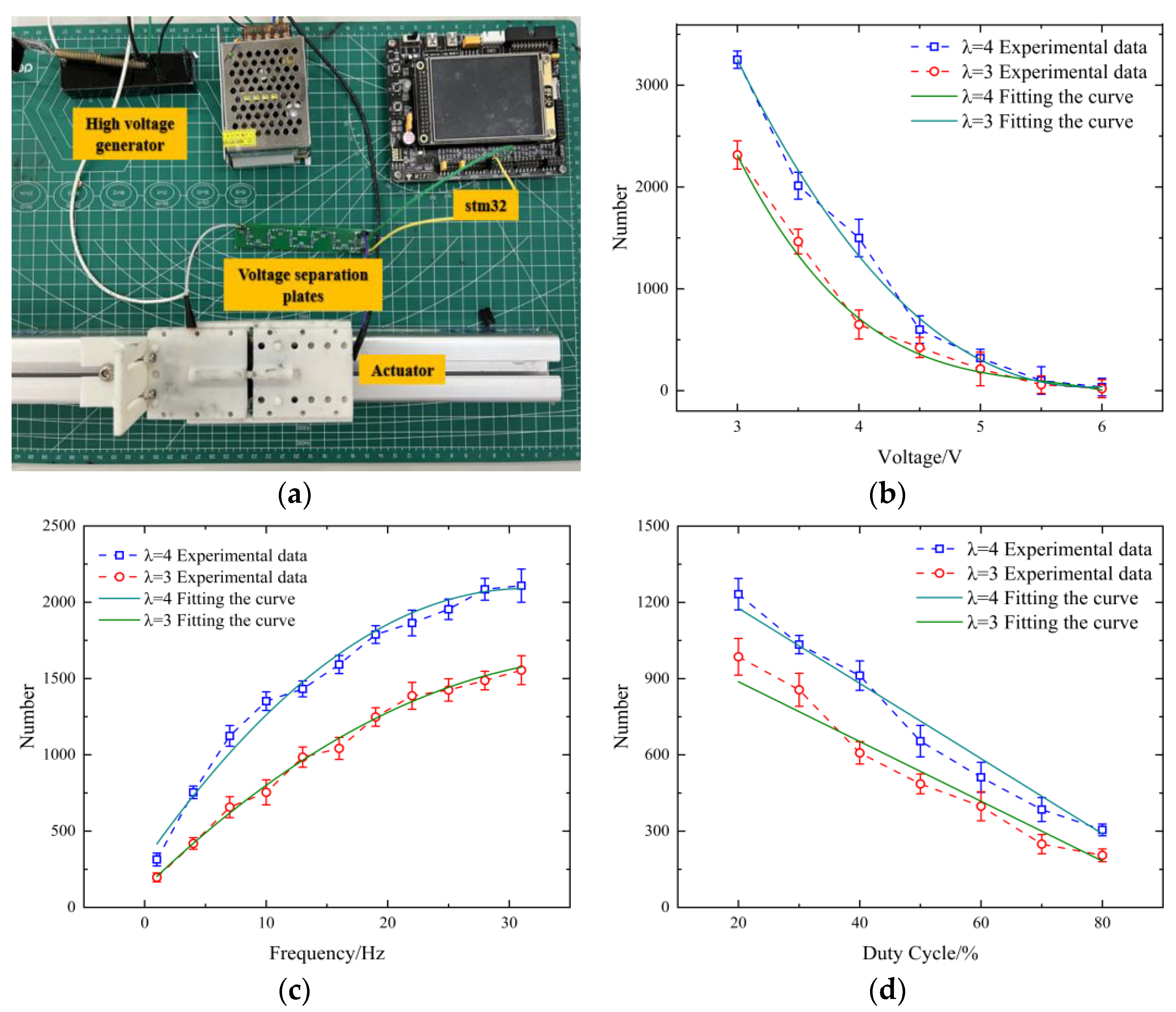
When making DE actuators or researching DE materials, it has often been observed that dielectric elastomer materials fail under the action of external forces or when high voltage is applied. The crawling actuator presented in this paper mainly relies on the expansion and contraction of the DE membrane to realize the movement of the robot, so it is imperative to study the cycle times of the DE membrane. The fatigue failure of the DE membrane is dynamic. Different waveforms of voltage in the experiment affected the deformation of DE membrane, thus directly affecting the number of actuators. The experimental apparatus is shown in Figure 7a; one end of the drive can be fixed and the other end can be retracted. When the DE membrane is broken down, the high-voltage generator short-circuits and the current stops automatically. Using this characteristic, this paper provides a method to detect the voltage and count it with a single-chip computer. First, a sub plate was designed in which the resistance string is ten 20 M resistors and one 200 K resistor in series. The 200 K resistor in the dividing plate is connected in parallel with a capacitor. One end of the 10 M resistor is connected in series with the positive end of the high-voltage power supply, and the 200 K resistor and the capacitor in parallel with the negative end of the high-voltage power supply. The output voltage value was measured by means of resistance voltage division, so that the voltage measured by the microcontroller was controlled at 0–5 v. The sub plate and the actuator were connected in parallel, and finally stm32 connected to both ends of the 200 K resistor. The microcontroller ADC module starts timing at the moment when it detects the voltage. When the DE membrane is broken down, the microcontroller stops timing when the voltage is 0. Finally, the time recorded by the microcontroller was divided by the frequency of the square wave to obtain the number of cycles.
It can be seen from Figure 7b that with the increase of voltage, the cycle times of the DE membrane gradually decreased. It was shown in a previous article that with the increase of voltage, the Maxwell force on the DE membrane is constantly increasing. The number of cycles that the film can cycle before failure is reduced due to the increase of stress. It can be seen from Formula τ m = λ 0 λ t ( U l ) 2 that Maxwell stress is proportional to the square of the voltage, so this function shows a relationship similar to the inverse quadratic function image. This view can also be confirmed from the fitting curve in the figure.
As shown in Figure 7c, indicating the relationship between the voltage frequency and the number of cycles of the DE membrane, when the voltage was a square wave the number of cycles of the DE membrane was proportional to the frequency of the voltage. The specific reason is that the Maxwell stress of DE membrane changes slowly at low frequency, with a certain hysteresis compared with high frequency, so the deformation amplitude at low frequency is smaller, and the field strength at low frequency is higher, so the cycle times at high frequency are greater than that at low frequency.
It can be seen from Figure 7d that with the increase of duty cycle, the number of fatigue failures gradually decreased, finally to a relatively small value. When the voltage exceeded its bearing range, the fatigue damage included breakdown damage due to the high voltage. The reason for this is that as the duty cycle increases, the high-voltage time takes more time in the power-on cycle, and the Maxwell force on the DE membrane takes more time. After increasing the force duration, the fatigue failure of the DE membrane occurs in advance, and the corresponding cycle times are correspondingly reduced. Because its duty cycle increased linearly, the reduction of fatigue failure times also presented a linear relationship. The possible errors in the figure may be caused by manual production, in which even the same steps may lead to different results due to small errors that we can only try to avoid through more elaborate production and multiple experiments.

4. Conclusions

This article presents the design of a crawling actuator capable of bearing a large load. The design principle was that dielectric elastomer can deform when energized, and the performance of the actuator was tested. This paper mainly discusses the manufacturing method, theoretical model, and experimental testing of the DE actuator. A crawling actuator was constructed with a unidirectional friction foot, and its crawling performance was theoretically studied and experimentally verified. In the simulation research, an interpolation fitting estimation algorithm (IFEA) was constructed according to the characteristics and principles of the materials. Through this algorithm, the verification results showed that the actuator had better driving performance when the membrane pre-stretching ratio was equal to 3. Finally, the pre-stretching of the film was determined. The method mainly involved experiments using frequency and duty cycle. The actuator attained a speed of 46 mm/s under 4 kv voltage, and maintained good speed under high load. Finally, the method improved the actuator’s steering and crawling performance, which were tested through experiments. From the experimental results it can be concluded that the actuator obtained excellent turning capability under conditions of 4 kv and 30 Hz. Through the above experiments and improvements, the actuator demonstrated better crawling performance than other drivers with high load capacity.

Author Contributions

Conceptualization, H.L. and C.Y.; methodology, H.L.; software, Z.X.; validation, H.L., C.Y. and M.L.; formal analysis, H.L.; investigation, H.L.; resources, H.L.; data curation, H.L.; writing—original draft preparation, H.L. and C.Y.; writing—review and editing, C.Y.; visualization, C.Y. and Z.X.; supervision, H.L.; project administration, R.Z.; funding acquisition, R.Z. All authors have read and agreed to the published version of the manuscript.

Funding

This research received no external funding.

Data Availability Statement

Not applicable.

Conflicts of Interest

The authors declare no conflict of interest.

References

  1. Resh, V.H.; Carde, R.T. Encyclopedia of Insects; Elsevier/Academic Press: Amsterdam, The Netherlands, 2009. [Google Scholar]
  2. Hoffman, K.L.; Wood, R.J. Myriapod-like ambulation of a segmented microrobot. Auton. Robot. 2011, 31, 103–114. [Google Scholar] [CrossRef]
  3. Trimmer, M.B.; Ewoldt, P.R.H.; Kovac, M.; Lipson, H.; Lu, N.; Shahinpoor, M.; Majidi, C. At the cross-roads: Interdisciplinary paths to soft robots. Soft Robot. 2014, 1, 63–69. [Google Scholar] [CrossRef]
  4. Shepherd, R.F.; Ilievski, F.; Choi, W.; Whitesides, G.M. Multigait soft robot. Proc. Natl. Acad. Sci. USA 2011, 108, 20400–20403. [Google Scholar] [CrossRef] [PubMed] [Green Version]
  5. Morin, S.A.; Shepherd, R.F.; Kwok, S.W.; Stokes, A.A.; Nemiroski, A.; Whitesides, G.M. Camouflage and Display for Soft Machines. Science 2012, 337, 828–832. [Google Scholar] [CrossRef] [PubMed] [Green Version]
  6. Breedon, P.; Coulter, F.; Vloeberghs, M. Dynamic facial prosthetics for sufferers of facial paralysis. Australas. Med. J. 2011, 4, 555–562. [Google Scholar] [CrossRef]
  7. Brown, E.; Rodenberg, N.; Amend, J.; Mozeika, A.; Steltz, E.; Zakin, M.R.; Lipson, H.; Jaeger, H.M. Universal robotic gripper based on the jamming of granular material. Proc. Natl. Acad. Sci. USA 2010, 107, 18809–18814. [Google Scholar] [CrossRef] [Green Version]
  8. Trimmer, B.A. A journal of soft robotics: Why now? Soft Robot. 2013, 1, 1–4. [Google Scholar] [CrossRef]
  9. Tian, B.; Liu, J.; Dvir, T.; Jin, L.; Tsui, J.H.; Qing, Q.; Suo, Z.; Langer, R.; Kohane, D.S.; Lieber, C.M. Macroporous nanowire nanoelectronic scaffolds for synthetic tissues. Nat. Mater. 2012, 11, 986–994. [Google Scholar] [CrossRef] [Green Version]
  10. Li, T.; Li, G.; Liang, Y.; Cheng, T.; Dai, J.; Yang, X.; Liu, B.; Zeng, Z.; Huang, Z.; Luo, Y.; et al. Fast-moving soft electronic fish. Sci. Adv. 2017, 3, e1602045. [Google Scholar] [CrossRef] [Green Version]
  11. Polygerinos, P.; Wang, Z.; Galloway, K.C.; Wood, R.J.; Walsh, C.J. Soft robotic glove for combined assistance and at-home rehabilitation. Robot. Auton. Syst. 2015, 73, 135–143. [Google Scholar] [CrossRef]
  12. Tolley, M.T.; Shepherd, R.; Mosadegh, B.; Galloway, K.C.; Wehner, M.; Karpelson, M.; Wood, R.J.; Whitesides, G.M. A Resilient, Untethered Soft Robot. Soft Robot. 2014, 1, 213–223. [Google Scholar] [CrossRef] [Green Version]
  13. Su, Z.; Yu, J.; Tan, M.; Zhang, J. Implementing Flexible and Fast Turning Maneuvers of a Multijoint Robotic Fish. IEEE/ASME Trans. Mechatronics 2014, 19, 329–338. [Google Scholar] [CrossRef]
  14. Kim, S.; Laschi, C.; Trimmer, B. Soft robotics: A bioinspired evolution in robotics. Trends Biotechnol. 2013, 31, 287–294. [Google Scholar] [CrossRef] [PubMed]
  15. Huang, Y.; Yu, Q.; Su, C.; Jiang, J.; Chen, N.; Shao, H. Light-Responsive Soft Actuators: Mechanism, Materials, Fabrication, and Applications. Actuators 2021, 10, 298. [Google Scholar] [CrossRef]
  16. Rus, D.; Tolley, M.T. Design, fabrication and control of soft robots. Nature 2015, 521, 467–475. [Google Scholar] [CrossRef] [PubMed] [Green Version]
  17. Cao, Y.; Shang, J.; Liang, K.; Fan, D.; Ma, D.; Tang, L. Review of soft-bodied robots. Chin. J. Theor. Appl. Mech. 2012, 48, 25–33. [Google Scholar] [CrossRef]
  18. Li, T.; Li, G.; Liang, Y.; Cheng, T.; Yang, X.; Huang, Z. Review of materials and structures in soft robotics. Chin. J. Theor. Appl. Mech. 2016, 48, 756–766. [Google Scholar]
  19. Wang, M.; Hao, Y.; Yang, X.; Wen, L. Soft robotics: Structure, actuation, sensing and control. J. Mech. Eng. 2017, 53, 1–13. [Google Scholar]
  20. Martinez, R.V.; Branch, J.L.; Fish, C.R.; Jin, L.; Shepherd, R.F.; Nunes, R.M.D.; Suo, Z.; Whitesides, G.M. Robotic tentacles with three-dimensional mobility based on flexible elastomers. Adv. Mater. 2013, 25, 205–212. [Google Scholar] [CrossRef]
  21. Lin, H.-T.; Leisk, G.G.; Trimmer, B. GoQBot: A caterpillar-inspired soft-bodied rolling robot. Bioinspir. Biomim. 2011, 6, 026007. [Google Scholar] [CrossRef]
  22. Ma, K.Y.; Chirarattananon, P.; Fuller, S.B.; Wood, R.J. Controlled Flight of a Biologically Inspired, Insect-Scale Robot. Science 2013, 340, 603–607. [Google Scholar] [CrossRef] [Green Version]
  23. Calisti, M.; Giorelli, M.; Levy, G.; Mazzolai, B.; Hochner, B.; Laschi, C.; Dario, P. An octopus-bioinspired solution to movement and manipulation for soft robots. Bioinspir. Biomim. 2011, 6, 036002. [Google Scholar] [CrossRef] [PubMed]
  24. Lipson, H. Challenges and Opportunities for Design, Simulation, and Fabrication of Soft Robots. Soft Robot. 2014, 1, 21–27. [Google Scholar] [CrossRef]
  25. Chan, V.; Park, K.; Collens, M.B.; Kong, H.; Saif, T.A.; Bashir, R. Development of Miniaturized Walking Biological Machines. Sci. Rep. 2012, 2, 857. [Google Scholar] [CrossRef] [PubMed] [Green Version]
  26. Shiao, Y.; Gadde, P. Investigation of Hysteresis Effect in Torque Performance for a Magnetorheological Brake in Adaptive Knee Orthosis. Actuators 2021, 10, 271. [Google Scholar] [CrossRef]
  27. Sanchez, C.J.; Chiu, C.-W.; Zhou, Y.; González, J.M.; Vinson, S.B.; Liang, H. Locomotion control of hybrid cockroach robots. J. R. Soc. Interface 2015, 12, 20141363. [Google Scholar] [CrossRef] [Green Version]
  28. Ewoldt, R.H. Extremely Soft: Design with Rheologically Complex Fluids. Soft Robot. 2014, 1, 12–20. [Google Scholar] [CrossRef]
  29. Copaci, D.; Blanco, D.; Moreno, L.E. Flexible Shape-Memory Alloy-Based Actuator: Mechanical Design Optimization According to Application. Actuators 2019, 8, 63. [Google Scholar] [CrossRef] [Green Version]
  30. Trivedi, D.; Rahn, C.D.; Kier, W.M.; Walker, I.D. Soft robotics: Biological inspiration, state of the art, and future research. Appl. Bionics Biomech. 2008, 5, 99–117. [Google Scholar] [CrossRef]
  31. Brochu, P.; Pei, Q. Dielectric Elastomers for Actuators and Artificial Muscles. Electroact. Polym. Mater. 2012, 1, 1–56. [Google Scholar]
Figure 1. (a) The picture shows the pre-stretching device of the DE membrane. The device mainly consists of aluminum alloy and the 3D-printed clamping device, the device can pre-stretch the DE membrane 3–6 times. (b,c) A sketch of the model of the actuator, consisting mainly of the housing, the spring, the DE membrane, and the support bar. (d) A diagram of the friction foot of the actuator, which provides backward friction so that the actuator can move forward. (e) The actuator was elongation tested and the elongation of the actuator after power applied was Δ x .
Actuators 11 00338 g001
Figure 2. Simplified model of the actuator and its parameters.
Actuators 11 00338 g002
Figure 3. (a) The algorithm results after inputting the length, width, and height of the membrane. (b) The graphs show the experimental data collected by the sensors, from which it can be seen that the real data and the results simulated by the algorithm are in good agreement.
Actuators 11 00338 g003
Figure 4. Flow Chart of IFEA Algorithm.
Actuators 11 00338 g004
Figure 5. (a) Diagram of the actuator after power on. (b) The figure shows the measuring device on the actuator. (c) The measured data, divided into theoretically calculated data and actual measured data. (d) The figure shows the actuator force test device, which is mainly used for measurement with the pressure sensor. (e) The graph shows the results of the driving force measurements and their fitted curves. (f) The actuator in the picture carries a camera, which acts as a heavy object. (g) The figure shows the crawling speed of the robot under different loads; results in the figure show that it maintained good performance even under four times its own weight.
Actuators 11 00338 g005aActuators 11 00338 g005b
Figure 6. (a) The diagram shows how the robot was improved to give it the ability to steer using two mutually independent actuators. (b,c) Turning ability under different duty cycles. The best turning was achieved at a duty cycle of 60%. (d) The figure shows the comparison of crawling performance after the modification. The figure shows that the straight-line capability after the improvement was about 80% of that before the advance.
Actuators 11 00338 g006
Figure 7. (a) The figure shows the fatigue count measuring device for the actuator. (b) Relationship between voltage and number of fatigue cycles. (c) Frequency in relation to number of fatigue cycles. (d) Duty cycle versus number of fatigue cycles.
Actuators 11 00338 g007
Table 1. Several different flexible material data [31].
MaterialMaximum Driving Strain (%)Maximum Stress (Mpa)Mass Energy Density (J/g)Volume Energy Density (J/cm3)Energy Conversion Efficiency (%)Corresponding Speed
Piezoelectric polymer0.21200.0140.11>89Slow
Silicone rubber dielectric elastomer643.30.760.7691Fast
Acrylic dielectric elastomer (VHB4910)3807.63.53.565–75Middle
Ion Gels>350.320.040.0532Slow
Human muscle>420.360.060.06>36Middle
Publisher’s Note: MDPI stays neutral with regard to jurisdictional claims in published maps and institutional affiliations.

