Abstract
Currently, the teaching programming or offline programming used by an industrial manipulator can manually set the running speed of the manipulator. In this paper, to consider the running speed and stability of the manipulator, the time-optimal trajectory planning (TOTP) of the manipulator is transformed into a nonlinear optimal value search problem under multiple constraints, and a time-search algorithm based on fuzzy control is proposed, so that the end of the manipulator can run along the given path in Cartesian space for the shortest time, and the angular velocity and angular acceleration of each joint is within a limited range. In addition, a simulation model of a 6-DOF manipulator is established in MATLAB, taking a straight-line trajectory of the end of the manipulator in Cartesian space as an example, and the effectiveness and efficiency of the algorithm proposed in this paper are proved by comparing the execution time with the bisection algorithm and the traditional gradient descent method.
1. Introduction
In current industrial production, both the teaching and offline programming can set the running speed of industrial manipulators, but the running speed of the manipulator is still relatively slow in many industrial applications. This is because reducing the running speed of the manipulator can reduce the angular velocity and angular acceleration of the joints of the manipulator, thereby reducing the vibration and jitter during the operation of the manipulator, improving its operation stability, and prolonging its service life [1]. However, reducing the running speed of the manipulator also reduces its production benefits [2,3].
Research into manipulators is divided into several aspects, such as manipulator control algorithms, trajectory planning and servo drive. Trajectory planning is an important part of the design process of manipulator control systems. At present, the mainstream research direction of trajectory planning is to optimize the trajectory of manipulators, including time optimization, jerk optimization [4], energy optimization [5], and multi-objective optimization considering time, jerk and energy [6]. In addition, manipulator obstacle avoidance [7] has become an increasing focus of trajectory planning.
The main goal of this paper is to perform TOTP in Cartesian space, making the planned trajectory time-optimal and smooth. Below, the research background and research methods of the TOTP of the manipulator will be elaborated from joint space and Cartesian space.
For TOTP in joint space, so far, there are some study methods, including limiting the joint torque rate [8], expressing joint torque and joint velocity constraints as functions of path coordinates to generate velocity limit curves [9], and the CPG method based on kinematic constraints [10]. Moreover, some algorithms are used to solve for TOTP, such as the bisection algorithm [11], input-shaping algorithm [12], hybrid-improved whale optimization and particle-swarm optimization (IWOA-PSO) algorithm [13], adaptive cuckoo search (ACS) algorithm [14], genetic algorithm (GA) [3,15], firefly algorithm [16], and simulated annealing (SA) algorithm [17]. Deep learning is also used to plan the trajectory of the grasping movement of the manipulator [18], which greatly shortens the calculation time of trajectory planning.
The above methods can plan a time-optimal and smooth trajectory; however, the TOTP in joint space only allows the manipulator to perform point-to-point (PTP) tasks, such as handling, pick-and-place, and palletizing. If the end of the manipulator moves along straight lines, arcs, or free curves, it is necessary to plan a Cartesian space trajectory.
For the TOTP of Cartesian space, there are two study methods. The first considers the distance and velocity of the end effector along a specified path as the state vector and converts the nonlinear dynamic constraints of the manipulator into state-related constraints of acceleration along the path [2]. The second transforms the time-optimal path tracking problem into a convex optimal control problem of a single state [19]. On the basis of these two study methods, there is a method based on the reachability analysis theory to transform the TOTP problem and achieve efficient solutions through multiple linear programming [20], and the other method that transforms the TOTP problem into a finite-dimensional second-order cone programming problem [21]. The sequential quadratic programming method (SQP) [22] is also used to solve the TOTP of the end of the manipulator along the spline curve, taking into account the continuity of joint acceleration and jerk. However, none of the references [2,19,20,21] consider acceleration continuity at the end of the manipulator, therefore, during the moving process, the joint torque of the manipulator will change abruptly, resulting in vibration and shaking, which affect the stability and accuracy of the manipulator.
In view of the above research background, to solve the problem of joint space trajectory planning that can only perform PTP tasks, and to solve the problem of manipulator instability caused by the sudden change in joint torque in the TOTP in Cartesian space, this paper proposes a new offline algorithm for TOTP of manipulators based on fuzzy control, which makes the end of the manipulator run with the shortest time along a given path in Cartesian space and avoids sudden changes in the angular velocity and angular acceleration of each joint, thus compensating for the shortcomings of the above research. First, the kinematic and dynamic model of a universal 6-joint industrial robot is established. Subsequently, the TOTP problem of the manipulator is transformed into a nonlinear optimal value search problem under multiple constraints, and an adaptive time search algorithm based on fuzzy control (ATSA-FC) is proposed to calculate the shortest time of Cartesian space trajectory under the constraints of the angular velocity and angular acceleration of each joint of the manipulator. Furthermore, a simulation model of the above-mentioned manipulator is established in MATLAB. Taking a straight-line trajectory of the end of the manipulator in Cartesian space as an example, the method proposed in this paper is used to calculate the shortest time of this trajectory. At the same time, two common nonlinear search algorithms are also selected: the bisection algorithm (BA) [11,23] and the gradient descent method with constant proportional coefficient (GDM-CPC) [24]. The trajectory times and execution times of these two algorithms are compared with ATSA-FC proposed in this paper to verify the efficiency of ATSA-FC.
The remainder of this paper is organized as follows. Section 2 introduces kinematic and dynamic models of the manipulator. Section 3 introduces the trajectory planning method for the end of the manipulator. Section 4 introduces the transformation of TOTP to a nonlinear optimal value search problem and three TOTP algorithms used in this paper, which are BA, GDM-CPC, and ATSA-FC. Section 5 introduces the simulation of TOTP of the manipulator based on MATLAB. Section 6 presents the conclusions of this paper.
2. Manipulator Kinematics and Dynamics Model
The manipulator used in this paper is a 6-DOF wrist-separated manipulator which satisfies the Piper criterion and has a closed solution [25]. The position-level kinematic model of this type of manipulator is established using the standard D-H method, and the D-H parameters table of the manipulator is shown in Table 1.

Table 1.
D-H Parameter of the 6-DOF Manipulator.
Using the above D-H parameters, the schematic diagram of the manipulator in this paper is shown in Figure 1.
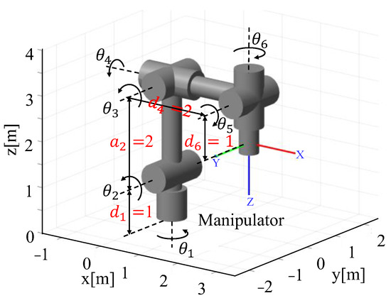
Figure 1.
Schematic of the manipulator.
Forward position-level kinematic of the manipulator solves the position and attitude of the end of the manipulator relative to the base by the given joint angles. Let be the homogeneous transformation matrix of the connecting rod coordinate system to . According to the D-H rule, is shown in Equation (1).
where , , , .
Therefore, the homogeneous matrix of the manipulator end coordinate system relative to the base coordinate system is shown in Equation (2).
This paper uses the axis/angle notation to represent the attitude at the end of the manipulator. For any rotation matrix R, it can be considered as a single rotation around an appropriate axis in space through an appropriate angle, and the axis/angle representation is shown in Equation (3).
where k is the unit vector defining the axis of rotation, is the angle rotated around axis k, and the pair (k,ϕ) is called the axis/angle representation of R [26].
Given any rotation matrix R, whose element is aij, the corresponding rotation angle ϕ and axis k are shown in Equations (4) and (5), respectively.
The axis/angle notation for the rotation matrix R is not unique because the rotation angle ϕ about axis k and the rotation angle −ϕ about axis −k are equivalent, as shown in Equation (6).
If ϕ = 0, then R is the identity matrix and axis k is not defined at this time. Because k is a unit vector, the equivalent axis/angle representation can be represented by a single vector r, and the vector r is shown in Equation (7).
where , , . The length of vector r is the angle ϕ, and the direction of vector r is the equivalent axis of rotation k.
Therefore, in addition to using a homogeneous transformation matrix to represent the position and attitude of the end of the manipulator, it can also be represented by a 6-dimensional vector , where is shown in Equation (8).
where , represent the positions of the end of the manipulator, , , represent the attitudes of the end of the manipulator.
The linear velocity and linear acceleration at the end of the manipulator are shown in Equations (9) and (10), respectively.
The attitude angular velocity and the attitude angular acceleration are shown in Equations (11) and (12), respectively.
According to Equations (9)–(12), the velocity at the end of manipulator and the acceleration at the end of manipulator are shown in Equations (13) and (14).
The transfer matrix between the joint angular velocity and the end velocity of the manipulator is called the Jacobian matrix J. The Jacobian matrix is a function of joint angle θ, as shown in Equation (15).
J = J(θ)
The forward velocity-level kinematic equation of the manipulator is shown in Equation (16).
where represents the joint velocity.
When J is a reversible square matrix, the inverse velocity-level kinematic equation of the manipulator can be obtained from Equation (16), as shown in Equation (17).
Taking the derivation of both sides of Equation (16), the forward acceleration-level kinematic equation of the manipulator can be obtained, as shown in Equation (18).
When J is a reversible square matrix, the inverse acceleration-level kinematic equation of the manipulator can be obtained from Equation (18), as shown in Equation (19).
is the derivative of the Jacobian matrix with respect to time, as shown in Equation (20).
The dynamic equation of the manipulator [8] is shown in Equation (21).
where is the inertia force matrix, is the cordial force and centrifugal force matrix, is the gravity term matrix, and is the joint torque vector.
3. Trajectory Planning
There are two main types of trajectory planning for manipulators; one is trajectory planning in joint space and the other is trajectory planning in Cartesian space [27]. Given that trajectory planning in joint space is not capable of high-precision work, this paper performs trajectory planning of Cartesian space for the manipulator, and then uses the kinematic model in Section 2 to obtain the corresponding joint-space trajectory.
The traditional trapezoidal velocity curve at the end of the manipulator is shown in Figure 2, and the acceleration curve of the trapezoidal velocity is shown in Figure 3. As shown in Figure 3, the acceleration curve of the trapezoidal velocity changes abruptly. It can be seen from Equation (19) that when the acceleration of the end of the manipulator changes abruptly, the angular acceleration of the joint also changes abruptly.
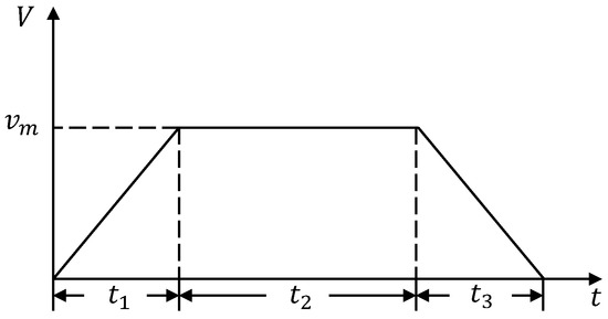
Figure 2.
Trapezoidal velocity curve.
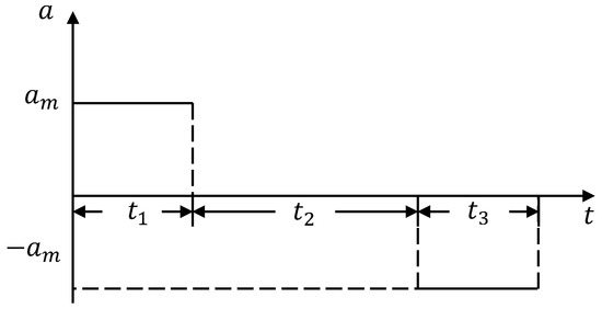
Figure 3.
Acceleration curve of trapezoidal velocity.
According to Equation (21), it can be shown that an abrupt change in the angular acceleration of the joint indicates an abrupt change in the torque of the joint motor, which causes mechanical vibration, impacting and affecting the accuracy and service life of the manipulator [28]. Conversely, a continuous change in joint angular velocity and angular acceleration causes a continuous change in joint torque. Therefore, in this paper, the S-shaped velocity curve [13] is used to replace the trapezoidal velocity curve shown in Figure 2. The S-shaped velocity curve is shown in Figure 4, and the acceleration curve of the S-shaped velocity is shown in Figure 5. The acceleration and deceleration segments of the S-shaped velocity curve are 5th order polynomials. It can be seen from Figure 4 and Figure 5 that the S-shaped velocity curve and acceleration curve of the S-shaped velocity change continuously. Equations (17) and (19) show that the joint angular velocity and angular acceleration of the manipulator change continuously, so the torque of the manipulator also changes continuously.
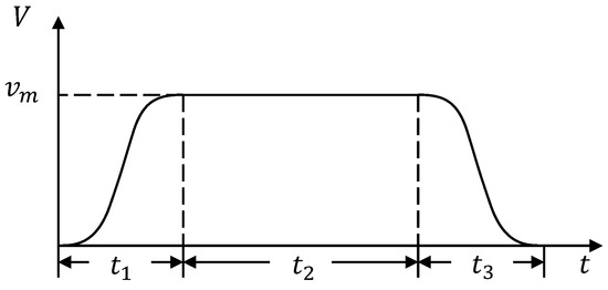
Figure 4.
S-shaped velocity curve.
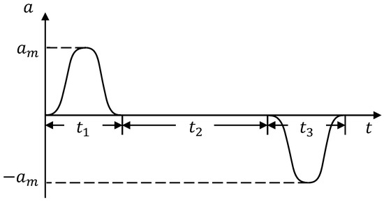
Figure 5.
Acceleration curve of the S-shaped velocity.
In this paper, trajectory planner P was designed to plan a trajectory with continuously changing acceleration in Cartesian space. P is represented by Equation (22).
where t is the trajectory running time, kt is the trajectory type, p is the constraint points set of the trajectory, which is represented by homogeneous matrices, r is the ratio of acceleration and deceleration time, and n is the number of trajectory points.
To plan a straight-line trajectory in Cartesian space, two constraint points are required and the distance between the two constraint points is used as the planning distance. To plan an arc trajectory, three constraint points are required, and the central angle of the arc where these three points are located is used as the planning distance.
Assuming that a straight-line trajectory is planned, the known spatial distance of the two constraint points is l, total running time is t, and ratio of acceleration to deceleration time is r.
The velocity v(x) of this trajectory is shown in Equation (23).
where denotes the 5th order polynomial velocity curve of the acceleration segment, denotes the velocity of the uniform velocity segment, and denotes the 5th order polynomial velocity curve of the deceleration segment.
Let, then can be written as Equation (27).
Because the first and second derivatives of and at , , and are both 0, and can be written as Equation (28).
Thus, can be written as Equation (29).
When a uniform velocity is obtained, the 5th order polynomial velocity planning can be performed.
Suppose the time period starting from to , the velocity of the end of the manipulator is , and is shown in Equation (30).
There are the following six boundary conditions,
The first-order derivative and the second-order derivative of are shown in Equations (31) and (32), respectively.
Substituting the above six boundary conditions into Equations (30)–(32), the following six equations can be obtained, as shown in Equations (33)–(38).
Equations (33)–(38) can be written in the form of matrix multiplication, as shown in Equation (39).
where
Because A is invertible, Equation (39) can be rewritten as Equation (40).
By substituting the boundary conditions of the acceleration, uniform velocity, and deceleration into Equation (40), the velocity change curve can be obtained, and the acceleration and displacement change curves can be obtained through differentiation and integration, respectively.
Similarly, the angular velocity and angular acceleration of the attitude at the end of the manipulator only need to be planned by changing the spatial distance l to the attitude angle ϕ.
Through the trajectory constraint points of the trajectory planner P, the attitude matrices and at the initial and final moments of the end of the manipulator can be determined, and is shown in Equation (41).
where is the rotation matrix that changes from to , and is shown in Equation (42).
Substituting into Equations (4) and (5), attitude rotation angle ϕ and rotation axis k can be obtained. The rotation matrix corresponding to the attitude of each trajectory point, is shown in Equation (43).
where represents the rotation angle corresponding to the i-th trajectory point, is the unit matrix of , is the antisymmetric matrix of vector k, and is shown in Equation (44).
4. Time-Optimal Trajectory Planning Algorithm
In this paper, the trajectory running time t is used as the control variable, the joint angular velocity and joint angular acceleration of the manipulator are used as the state variables, and the TOTP problem of the manipulator in Cartesian space is regarded as an optimal-value search problem under multiple constraints. In this paper, the minimum– maximum rule is used to solve the problem of multiple constraints, and avoids the situation of local optimal solution when using time-search algorithms to find the trajectory shortest time.
4.1. Problem Description of Time-Optimal Trajectory Planning
In the process of trajectory planning, if only the constraint condition of the angular acceleration of joint i is considered, then a time t can be found such that when the manipulator is running along the trajectory, the maximum angular acceleration of joint i reaches the angular acceleration constraint condition of joint i; t at this time is the shortest time that only considers the constraint condition of the angular acceleration of joint i. A block diagram of TOTP is shown in Figure 6. The joint parameters () after each trajectory planning and inverse kinematic were compared with the joint constraints, and a time search was performed.
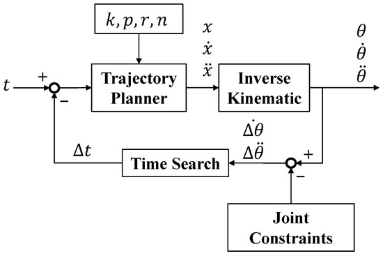
Figure 6.
The block diagram of time-optimal trajectory planning.
The joint constraints of the manipulator are listed in Table 2; represents the joint angular velocity constraint, represents the joint angular acceleration constraint. There were 12 constraints corresponding to the 12 shortest times. Using the minimum–maximum rule, the maximum value of the 12 shortest times is the shortest time of the trajectory.

Table 2.
Joint Constraints of The Manipulator.
If or satisfies Equations (45) and (46), joint i is considered to have reached the angular velocity or angular acceleration constraint.
Among them,
, and are the maximum angular velocity and maximum angular acceleration generated by the -th joint during operation, respectively.
Let be the shortest time that only considers the angular velocity constraint of joint i, is the shortest time that only considers the angular acceleration constraint of joint i, and is the shortest time that the manipulator runs along the Cartesian space trajectory. The problem of TOTP can be described by Equations (47)–(49).
where . are the position, velocity, and acceleration of the trajectory planner to plan the trajectory of the end of the manipulator in Cartesian space, respectively, and represents the inverse position-level kinematic.
It can be seen from Equations (47)–(49) that, to solve the shortest time, Equation (48) or Equation (49) needs to be calculated at least once. To solve , Equations (48) and (49) must be calculated at least 12 times. Therefore, to reduce the amount of calculation, let be the shortest time of the trajectory satisfying the angular velocity constraints of the six joints of the manipulator, and be the shortest time of the trajectory satisfying the angular acceleration constraints of the six joints of the manipulator. The shortest time of the Cartesian space trajectory can be expressed as Equations (50)–(52).
Solving requires calculating Equations (51) and (52) at least once, which reduces the amount of computation to 1/6 compared with using Equations (48) and (49). Considering the 12 constraints of the manipulator joints, the shortest time of the Cartesian space trajectory can be further expressed by Equation (53).
The can be obtained by computing Equation (53) at least once. The condition for determining whether the trajectory is time-optimal is shown in Equation (54).
Equation (53) describes the TOTP problem for the Cartesian spatial. Next, it is necessary to use a nonlinear search algorithm to determine the shortest time t of the trajectory, such that the trajectory of the joint space of the manipulator satisfies Equation (54).
4.2. Time-Search Algorithm
This section introduces three kinds of time-search algorithms, which are BA, GDM-CPC, and ATSA-FC. By judging whether the joint trajectory corresponding to the shortest time satisfies Equation (54), the validity of the trajectory is verified. By comparing the execution times of the three algorithms, the efficiency of the ATSA-FC algorithm is verified.
The BA is a widely used search method. Its computational complexity is O(log(n)). Therefore, despite the large amount of data, this search method ensures high computational efficiency [23]. The premise of using BA is that the data must be an ordered sequence, and the time series is exactly an ordered sequence, which makes it suitable for using BA. In this paper, the BA method was used to search for the shortest time of the trajectory in the time interval. The input time for the initial trajectory planner is. The flowchart of BA is shown in Figure 7.
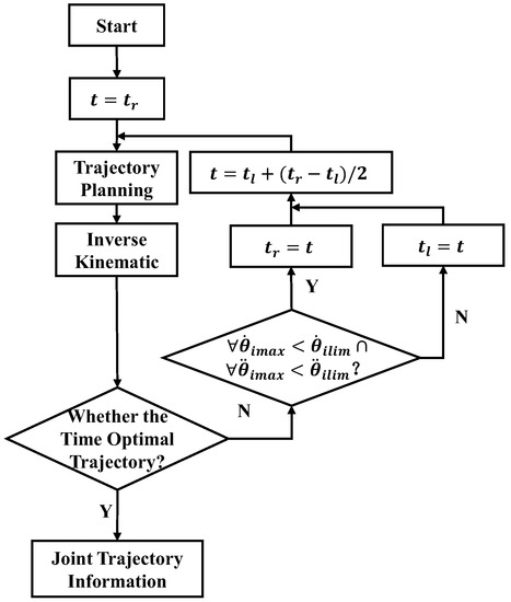
Figure 7.
The flow chart of BA.
The algorithm first uses as the running time to plan the trajectory. If the planning result does not satisfy the conditions of the time-optimal trajectory, it is necessary to determine whether the maximum angular velocity and maximum angular acceleration of all joints are within the constraints of the angular velocity and angular acceleration of the joints. The judgment condition is shown in Equation (55).
If the joint trajectory satisfies Equation (55), then let , otherwise, let . Then, let , input it into the trajectory planner as the running time of the trajectory, iterate continuously, and finally determine the shortest time .
However, these algorithms have limitations. When the shortest time of the trajectory is not in the given time interval, the algorithm will fail and enter an infinite loop, and the time of each planning will be infinitely close to the boundary of the given time interval.
Therefore, this paper uses GDM-CPC to solve this problem. GDM-CPC is a first-order optimization algorithm that can search for a local minimum of the function. Because this paper uses Equation (54) as the judgment condition of time-optimal trajectory, there is only one joint to reach its maximum constraint, and the angular velocity and angular acceleration of the other joints are less than their maximum constraint. Therefore, the use of GDM-CPC here will not fall into the local optimal situation, and must be able to obtain a shortest time of trajectory that satisfies all joint constraints. GDM-CPC first provides an initial trajectory running time , and then determines whether the joint trajectory satisfies Equation (54) after obtaining the joint trajectory of the manipulator through trajectory planning and inverse kinematics. If Equation (54) is not satisfied, then searching for a new trajectory running time, and the shortest running time of the trajectory, will finally be obtained. The advantage of this algorithm is that it only needs to provide a time value greater than 0 to converge to the shortest time of the trajectory, thereby avoiding the limitations of BA.
The flowchart of GDM-CPC is shown in Figure 8.
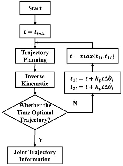
Figure 8.
The flow chart of GDM-CPC.
Among them, is shown in Equation (56) and is shown in Equation (57).
where is the time at which joint i is optimized with each time and is the time at which joint i is optimized with each time.
If , the current input time is small, and the maximum angular velocity of joint i exceeds its angular velocity constraint during the trajectory planning process. The time change is , which increases the input time to reduce the maximum angular velocity of joint i. If , the current input time is large, and the maximum angular velocity of joint i is less than its angular velocity constraint during the trajectory planning process. The time change is , reducing the input time to increase the maximum angular velocity of joint i. The joint angular acceleration has the same adjustment process. Take the maximum value of and and assign it to t as the input of the trajectory planner. In the continuous iterative process, the shortest time of the trajectory will be obtained.
Because must be adjusted many times, the algorithm will have fewer convergence steps. Therefore, this paper proposes an ATSA-FC. This method adaptively adjusts according to and by using fuzzy control.
Fuzzy control is a control method that combines an expert system, fuzzy set theory, and control theory, and is very different from traditional control theory based on the mathematical model of the controlled process [29]. The behavior and experience of human experts can be added to fuzzy control. Fuzzy control is practical when establishing a mathematical model for a controlled process is difficult.
This paper considers a design for a first-order fuzzy controller to adjust the value of . First, the input linguistic variable is fuzzified. Let the input linguistic variable be , where is the smallest absolute value between and . Let the domain of be , , and divide it into five fuzzy sets, which are NB, N, ZE, P, and PB, respectively. NB stands for negative big, N for negative, ZE for zero, P for positive, PB for positive big. The membership function corresponding to each fuzzy set is a Gaussian distribution function, as shown in Figure 9.
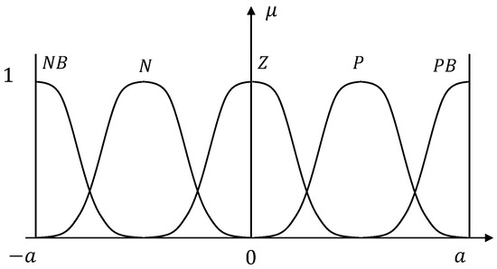
Figure 9.
The membership function corresponding to the input fuzzy set.
The expression of the membership function for each fuzzy set is shown in Equation (58).
where −a < x < a.
Second, the output linguistic variable is fuzzified. Let the output linguistic variable be , and let the domain of be , , and divided into three fuzzy sets, which are S, M, L. S represents small values, M represents medium values, and L represents large values. The membership function corresponding to each fuzzy set is a Gaussian distribution curve, as shown in Figure 10.
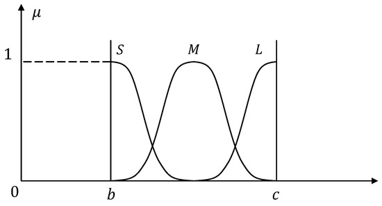
Figure 10.
The membership function corresponding to the output fuzzy set.
The expression of the function corresponding to each fuzzy set is shown in Equation (59).
where b < y < c.
Fuzzy control rules are then established and fuzzy reasoning is performed. After determining the fuzzy sets of the input and output linguistic variables, fuzzy conditional statements in the form of an IF–THEN are used to establish fuzzy control rules. The fuzzy rules are as follows:
When is NB or PB, it indicates that the difference between the maximum joint angular velocity or maximum angular acceleration and the constraints is large. At this time, a larger value should be output and the convergence step should be increased. When is N or P, it indicates that the difference is medium, and a medium value should be output at this time. When is Z, it indicates that the difference is small. A small value should be output to reduce the convergence step and avoid repeated oscillations.
The flowchart of ATSA-FC is shown in Figure 11.
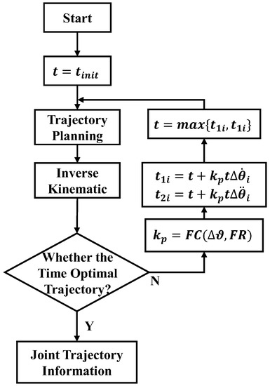
Figure 11.
The flow chart of ATSA-FC.
The FC is the fuzzy control function, and the FR is the fuzzy control rule, and Δϑ is shown in Equation (60).
Take the maximum value of and and assign it to t as the input of the trajectory planner. In the continuous iterative process, the shortest time t of the trajectory will be obtained.
5. Simulation
The simulation section first sets the parameters of the simulation, and then analyses the simulation results.
5.1. Parameter Setting of the Simulation
This paper simulates TOTP based on the MATLAB environment. The Robotics Toolbox is used to establish the manipulator.
The constraints of each joint angular velocity and angular acceleration set in the simulation environment are listed in Table 3.

Table 3.
Joint Constraints of the Simulation Environment.
The position and attitude of the end of the manipulator is set at the initial and end moments of the straight-line path, which are represented by homogeneous matrices and , respectively. is shown in Equation (61) and is shown in Equation (62).
Set the initial time of the trajectory planner P to t = 10 s, n = 1000, the ratio of acceleration and deceleration time to r = 0.3, the trajectory type to be a straight-line, and the constraint points to be and .
The linear trajectory of the end of the manipulator in Cartesian space is shown in Figure 12. The red triangle represents the starting point and the red circle represents the end point.
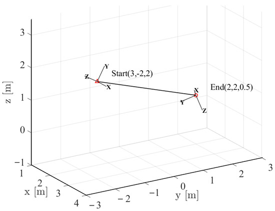
Figure 12.
Straight-line trajectory in Cartesian space.
Using Equation (42), the rotation transformation matrix of the attitude at the initial and end moments is calculated, and is shown in Equation (63).
From Equations (4) and (5), the rotation axis/angle representation of can be obtained, and the rotation angle is shown in Equation (64), the axis of rotation k is shown in Equation (65).
ϕ = 137.7448°
For fuzzy control, the Fuzzy Logic Toolbox in MATLAB is used in this paper to build a fuzzy inference system.
The membership function of each fuzzy set of input linguistic variables is shown in Equation (58), where x∈[−1, 1], σ = 0.2142. The membership function of each fuzzy set of output linguistic variables is shown in Equation (59), where y∈[0.35, 1], σ = 0.1. The membership function corresponding to the input linguistic variables and output linguistic variables are shown in Figure 13. For input linguistic variable, x∈[−1, 1], which is due to the normalization of Equations (56) and (57). In order to ensure the completeness of the membership function [30], the membership degree at the intersection of the two membership functions is 0.5, combined with the experience summarized in the simulation debugging process of this study, the σ can be set to be 0.2142. For output language variable, it has three fuzzy sets. In order to make the membership of S and L at 0.675 tend to 0, so that the output has better clarity, the σ can be set to be 0.1.
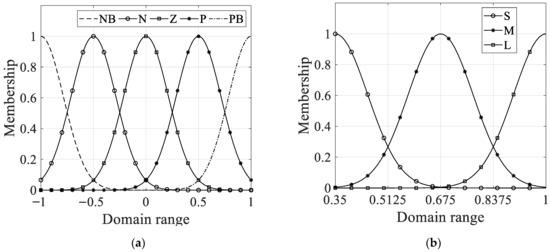
Figure 13.
The membership function corresponding linguistic variable: (a) input linguistic variable; (b) output linguistic variable.
Using the fuzzy rules established in Section 4, the mapping curve of the input and output of the fuzzy control is obtained, as shown in Figure 14.
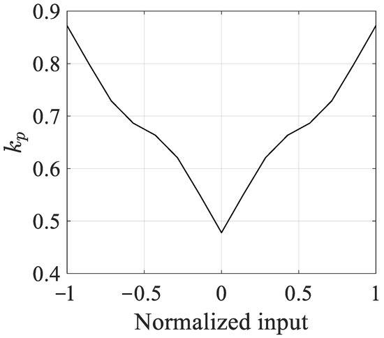
Figure 14.
The input and output mapping curve.
5.2. Results of the Simulation
The convergence curves of the controlled time of the three algorithms using BA, GDM-CPC with , and ATSA-FC are shown in Figure 15.
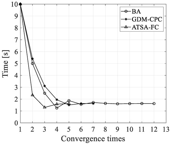
Figure 15.
Convergence curve of controlled time of three algorithms.
As shown in Figure 16, under the same initial conditions, to get the trajectory shortest time, BA required 12 times, GDM-CPC required seven times, and ATSA-FC required five times. It can also be seen that the convergence curves of the controlled time of these three algorithms have oscillation phenomena, in which the convergence step of BA at each iteration is taken as half of the updated time interval at each iteration, since BA simply adjusts the time and does not take into account the difference with the constraint. It has the largest number of convergence steps. GDM-CPC has the smallest convergence step size at the first convergence and produces the smallest oscillation amplitude. The ATSA-FC has the largest convergence step size at the first convergence, but there is only one oscillation phenomenon, and the shortest time to the trajectory is obtained by using the least number of convergence steps, which reflects the superiority of ATSA-FC.
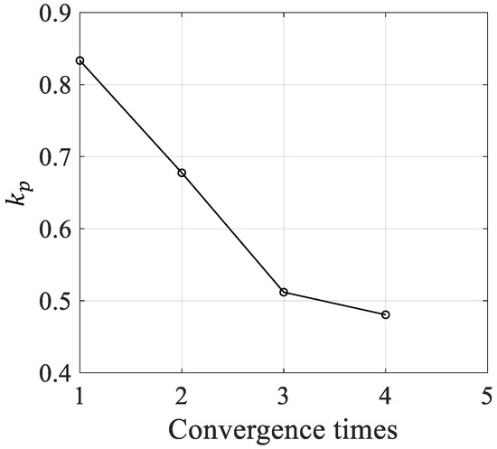
Figure 16.
changes with input at each iteration.
The variation in with the number of convergences is shown in Figure 16. The value obtained from the current iteration is used to update the input time for the next trajectory planning. Because the input time of the 5th trajectory planning meets the shortest time requirement of the trajectory, has only four iterations.
The trajectory shortest times obtained by three algorithms are listed in Table 4.

Table 4.
The trajectory shortest time solved by the three algorithms.
It can be seen from Table 4 that the trajectory shortest time planned by BA is the largest, which is 1.6260 s. The trajectory shortest time planned by GDM-CPC is 1.6248 s, which is 1.2 ms less than that of BA. The trajectory shortest time planned by ATSA-FC is 1.6237 s, which is 2.3 ms less than that of BA. Since the judgment condition for reaching the maximum joint parameter specified in Equations (45) and (46) is 99.6–100% of the joint constraints, the trajectory shortest time difference obtained by these three algorithms is very small.
The execution times of the three algorithms are measured using the timing function in MATLAB, as listed in Table 5.

Table 5.
Execution time of three algorithms.
As shown in Table 5, the execution time of BA is 8.38 s, and the execution time of GDM-CPC is 5.26 s, which is 37.23% less than that of BA. The execution time of ATSA-FC is 4.24 s, which is 19.39% less than that of GDM-CPC and 49.40% less than that of BA, which proves the efficiency of the ATSA-FC proposed in this paper.
Using the trajectory shortest time obtained by the ATSA-FC, S-shaped velocity planning of the end of the manipulator along the trajectory in Figure 12 is performed. The change curves of the joint angle, angular velocity, and angular acceleration are shown in Figure 17.

Figure 17.
The change curves of each joint: (a) angle; (b) angular velocity; (c) angular acceleration.
As shown in Figure 17, the angular velocity and angular acceleration of each joint obtained by using the S-shaped velocity curve change continuously, and it can be inferred that the operation of the manipulator is stable. It can be seen from Figure 17b,c that in the process of TOTP in Cartesian space, the maximum angular acceleration of joint 3 plays a major limiting role, satisfying the maximum angular acceleration judgment condition of the joint. The angular velocity and angular acceleration of other joints do not reach their constraints. This also shows that it is feasible to use the minimum–maximum rule to solve the multi-constraint problem in TOTP.
Because the shortest times of the trajectories obtained by these three algorithms are very close, the difference between the overall angular velocity and angular acceleration cannot be seen in the comparison chart, so only the local enlarged pictures at the maximum angular velocity and maximum angular acceleration of the joint are given here, as shown in Figure 18.
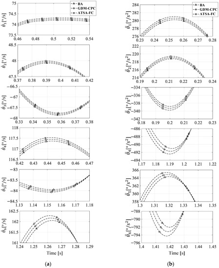
Figure 18.
Comparison of joint maximum angular information planned by three algorithms: (a) angular velocity; (b) angular acceleration.
It can be seen from Figure 18a,b that the angular velocity and angular acceleration of the joint are negatively correlated with the trajectory time of the manipulator. Since the ATSA-FC calculates the minimum trajectory shortest time, the corresponding joint trajectory also has the largest peak.
To determine the trajectory planning effect of these three algorithms, beyond comparing the shortest time of the trajectory, it can also be measured by using the degree of TOTP. The degree of TOTP can be described by the ratio of the maximum joint parameters that plays the major limitation role in the joint constraints, and in this simulation, joint 3′s acceleration plays the major role, so the degree of TOTP can be calculated by Equation (66).
When using BA, GDM-CPC and ATSA-FC, the , , and of each joint at trajectory shortest time are shown in Table 6, Table 7 and Table 8, respectively.

Table 6.
The joint information table of BA.

Table 7.
Joint information table of GDM-CPC.

Table 8.
Joint information table of ATSA-FC.
As shown in Table 6, Table 7 and Table 8, the maximum angular velocity and angular acceleration of the six joints are within the joint constraints, and the maximum angular accelerations of joint 3 planned by these three algorithms are 338.8432, 339.3172, and 339.8017, and their degrees of TOTP are 99.66%, 99.80%, and 99.94%, respectively. The maximum angular acceleration constraints of joint 3 are , , and the maximum angular acceleration of joint 3 planned by these three algorithms are all within . Therefore, the joint trajectories planned by these three algorithms satisfy Equation (54), which proves that the shortest time of the trajectory obtained by the above three algorithms is effective, and ATSA-FC has the highest degree of TOTP.
In fact, the degree of TOTP is not only related to the algorithm itself, but also to the judgment condition’s range set in Equations (45) and (46), which determines the upper and lower limits of the degree of TOTP. In the simulation, the judgment condition’s range is 99.6%–100% of the maximum joint parameters, so according to Equation (54), no matter how the algorithm is run, the degree of TOTP will always be between 99.6% and 100%.
Adjust Equations (45) and (46) and simulate a different range of judgment conditions. The trajectory shortest times and algorithm execution times planned by each algorithm are listed in Table 9. Let and , where Er is the lower limit of degree of TOTP.

Table 9.
The table of each algorithm’s execution time and the trajectory shortest time.
As shown in Table 9, under all Er conditions, the ATSA-FC had the shortest execution time. In addition, among the three algorithms, the trajectory shortest time planned by ATSA-FC is also the smallest. Thus, the superiority and effectiveness of the ATSA-FC are verified.
6. Conclusions
In this paper, the problem of TOTP of the manipulator in Cartesian space is studied, and ATSA-FC is proposed, so that the end of the manipulator can run along the given trajectory of Cartesian space with the shortest running time, while avoiding the sudden change in torque of each joint.
In the simulation, taking a straight-line path of the manipulator in Cartesian space as an example, BA, GDM-CPC, and ATSA-FC are used to calculate the shortest time of this trajectory. By comparing the trajectory shortest time and the execution time of these three algorithms, the superiority and efficiency of the proposed algorithm is proved. The main contributions of this article are as follows:
- An adaptive time-search algorithm based on fuzzy control is proposed, which can adaptively adjust the time-search step by using fuzzy control based on the results of the previous feedback. The algorithm execution time and the degree of TOTP is better than BA and GDM-CPC.
- The TOTP problem is transformed into a nonlinear optimization problem under multi-constraints, and the minimum–maximum rule is used to consider the multi-constraints, as shown in Equations (53) and (54), to avoid falling into the situation of local optimal solution when using the time-search algorithm.
- The range of maximum judgment conditions is 99.6–100% of the maximum joint parameters, as shown in Equations (45) and (46), which can reduce the number of iterations and have little impact on the maximum running speed of the trajectory. At the same time, this range also specifies the upper and lower limits of the optimal trajectory planning degree of time.
In conclusion, the TOTP algorithm based on fuzzy control proposed in this study is not only efficient, but also calculates the shortest trajectory time under the same trajectory constraints.
In the follow-up, based on the research in this paper, the dynamic constraints of the manipulator and the quality of the links and joints will be considered, and the TOTP will be carried out under the dynamic constraints.
Author Contributions
Conceptualization, Q.H.; methodology, Q.H.; software, F.H.; supervision, Q.H.; validation, F.H.; visualization, F.H.; writing—original draft, F.H.; writing—review and editing, F.H. and Q.H. All authors have read and agreed to the published version of the manuscript.
Funding
This research received no external funding.
Institutional Review Board Statement
Not applicable.
Informed Consent Statement
Not applicable.
Data Availability Statement
Not applicable.
Conflicts of Interest
The authors declare no conflict of interest.
References
- Huang, J.; Hu, P.; Wu, K.; Zeng, M. Optimal time-jerk trajectory planning for industrial robots. Mech. Mach. Theory 2018, 121, 530–544. [Google Scholar] [CrossRef]
- Bobrow, J.E.; Dubowsky, S.; Gibson, J.S. Time-optimal control of robotic manipulators along specified paths. Int. J. Robot. Res. 1985, 4, 3–17. [Google Scholar] [CrossRef]
- Yu, X.; Dong, M.; Yin, W. Time-optimal trajectory planning of manipulator with simultaneously searching the optimal path. Comput. Commun. 2022, 181, 446–453. [Google Scholar] [CrossRef]
- Wang, F.; Wu, Z.; Bao, T. Time-Jerk optimal Trajectory Planning of Industrial Robots Based on a Hybrid WOA-GA Algorithm. Processes 2022, 10, 1014. [Google Scholar] [CrossRef]
- Zhang, X.; Shi, G. Multi-objective optimal trajectory planning for manipulators in the presence of obstacles. Robotica 2022, 40, 888–906. [Google Scholar] [CrossRef]
- Garriz, C.; Domingo, R. Trajectory Optimization in Terms of Energy and Performance of an Industrial Robot in the Manufacturing Industry. Sensors 2022, 22, 7538. [Google Scholar] [CrossRef]
- Yu, Y.; Zhang, Y. Collision avoidance and path planning for industrial manipulator using slice-based heuristic fast marching tree. Robot. Comput. Integr. Manuf. 2022, 75, 102289. [Google Scholar] [CrossRef]
- Constantinescu, D.; Croft, E.A. Smooth and Time-Optimal Trajectory Planning for Industrial Manipulators along Specified Paths. J. Robot. Syst. 2000, 17, 233–249. [Google Scholar] [CrossRef]
- Ding, Y.; Wang, Y.; Chen, B. Smooth and Proximate Time-Optimal Trajectory Planning of Robotic Manipulators. Trans. Can. Soc. Mech. Eng. 2022, 46, 466–476. [Google Scholar] [CrossRef]
- Fang, Y.; Hu, J.; Liu, W.; Chen, B.; Qi, J.; Ye, X. A CPG-Based Online Trajectory Planning Method for Industrial Manipulators. In Proceedings of the 2016 Asia-Pacific Conference on Intelligent Robot Systems (ACIRS), Tokyo, Japan, 20–24 July 2016. [Google Scholar] [CrossRef]
- Barnett, E.; Gosselin, C. A Bisection Algorithm for Time-Optimal Trajectory Planning Along Fully Specified Paths. IEEE Trans. Robot. 2021, 37, 131–145. [Google Scholar] [CrossRef]
- Zhang, T.; Zhang, M.; Zou, Y. Time-optimal and Smooth Trajectory Planning for Robot Manipulators. Int. J. Control Autom. Syst. 2021, 19, 521–531. [Google Scholar] [CrossRef]
- Zhao, J.; Zhu, X.; Song, T. Serial Manipulator Time-Jerk Optimal Trajectory Planning Based on Hybrid IWOA-PSO Algorithm. IEEE Access 2022, 10, 6592–6604. [Google Scholar] [CrossRef]
- Zhang, L.; Wang, Y.; Zhao, X.; Zhao, P.; He, L. Time-optimal Trajectory Planning of Serial Manipulator based on Adaptive Cuckoo Search Algorithm. J. Mech. Sci. Technol. 2021, 35, 3171–3181. [Google Scholar] [CrossRef]
- Liu, Y.; Guo, C.; Weng, Y. Online Time-optimal Trajectory Planning for Robotic Manipulators Using Adaptive Elite Genetic Algorithm with Singularity Avoidance. IEEE Access 2019, 7, 146301–146308. [Google Scholar] [CrossRef]
- Guo, X.; Bo, R.; Jia, J.; Li, R. Time-optimal Trajectory Planning of Manipulator Based on Improved Firefly Algorithm. Mach. Des. Res. 2021, 37, 55–59. [Google Scholar] [CrossRef]
- Zhu, Y.; Jiao, J. Automatic Control System Design for Industrial Robots Based on Simulated Annealing and PID Algorithms. Adv. Multimed. 2020, 2022, 9226576. [Google Scholar] [CrossRef]
- Ichnowski, J.; Avigal, Y.; Satish, V.; Goldberg, K. Deep learning can accelerate grasp-optimized motion planning. Sci. Robot. 2022, 5, eabd7710. [Google Scholar] [CrossRef]
- Verscheure, D.; Demeulenaere, B.; Swevers, J.; De Schutter, J.; Diehl, M. Time-Optimal Path Tracking for Robots: A Convex Optimization Approach. IEEE Trans. Automat. Contr. 2009, 54, 2318–2327. [Google Scholar] [CrossRef]
- Pham, H.; Pham, Q.C. A New Approach to Time-Optimal Path Parameterization Based on Reachability Analysis. IEEE Trans. Robot. 2018, 34, 645–659. [Google Scholar] [CrossRef]
- Shen, J.; Kong, M.; Zhu, Y. Trajectory Optimization Algorithm Based on Robot Dynamics and Convex Optimization. In Proceedings of the 2019 IEEE 3rd Advanced Information Management, Communicates, Electronic and Automation Control Conference (IMCEC), Chongqing, China, 11–13 October 2019. [Google Scholar] [CrossRef]
- Liu, H.; Lai, X.; Wu, W. Time-optimal and jerk-continuous trajectory planning for robot manipulators with kinematic constraints. Robot. Comput. -Integr. Manuf. 2013, 29, 309–317. [Google Scholar] [CrossRef]
- Zhu, K.G.; Shi, G.Y.; Liu, J. Improved flattening algorithm for NURBS curve based on bisection feedback search algorithm and interval reformation method. Ocean Eng. 2022, 247, 110635. [Google Scholar] [CrossRef]
- Xue, Y.; Wang, Y.; Liang, J. A self-adaptive gradient descent search algorithm for fully-connected neural networks. Neurocomputing 2022, 478, 70–80. [Google Scholar] [CrossRef]
- Liang, B.; Xu, W. Space Robotics: Modeling, Planning and Control; Tsinghua University Press: Beijing, China, 2017; pp. 93–94. ISBN 978-7-302-47258-2. [Google Scholar]
- Spong, M.W.; Hutchinson, S. Robot Modeling and Control; John Wiley & Sons Inc.: New York, NY, USA, 2005; pp. 57–60. ISBN 978-0-471-64990-8. [Google Scholar]
- Gasparetto, A.; Zanotto, V. A technique for time-jerk optimal planning of robot trajectories. Robot. Comput. Integr. Manuf. 2008, 24, 415–426. [Google Scholar] [CrossRef]
- Wan, J.; Wu, H.; Ma, R.; Zhang, L. A study on avoiding joint limits for inverse kinematics of redundant manipulators using improved clamping weighted least-norm method. J. Mech. Sci. Technol. 2018, 32, 1367–1378. [Google Scholar] [CrossRef]
- Driankov, D.; Hellendoorn, H.; Reinfrank, M. An Introduction to Fuzzy Control; Springer Science & Business Media: Berlin/Heidelberg, Germany, 2013; pp. 1–3. ISBN 978-3-662-11131-4. [Google Scholar]
- Su, J.; Ren, J.; Pan, H. An improved self-structuring neuro-fuzzy algorithm. In Proceedings of the 2008 International Conference on Information and Automation, Changsha, China, 20–23 June 2008. [Google Scholar] [CrossRef]
Publisher’s Note: MDPI stays neutral with regard to jurisdictional claims in published maps and institutional affiliations. |
© 2022 by the authors. Licensee MDPI, Basel, Switzerland. This article is an open access article distributed under the terms and conditions of the Creative Commons Attribution (CC BY) license (https://creativecommons.org/licenses/by/4.0/).