1. Introduction
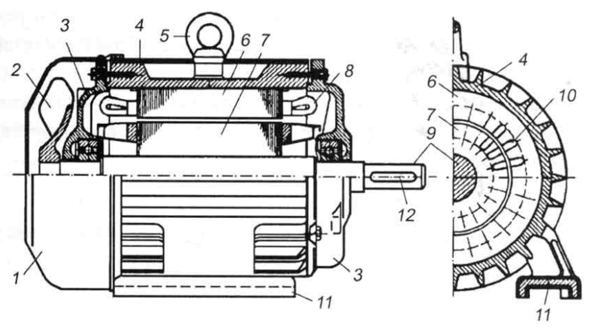
An asynchronous machine shown in
Figure 1, consists of a stator and a rotor. A stator consists of a solid frame that is mostly cast iron. There is a cylindrical magnetic circuit consisting of steel sheets with stamped slots for windings placed in it. In the case of three-phase windings, each phase is placed in one-third of the slots around the air gap. A three-phase winding is designed in such a way that it creates a rotating magnetic field as soon as it is supplied with a three-phase current [
1].
A rotating magnetic field in the stator is created if the stator windings of a motor at a standstill are connected to a three-phase voltage system. The field lines of the given field cross the conductors of the rotor winding, and the time-varying magnetic flux induces a voltage in the rotor resulting in the current beginning to flow through the rotor. The frequency of rotor voltage and current is directly given by the stator current frequency when the rotor is at a standstill. The state in which the stator winding is powered by a three-phase voltage system and the rotor has zero speed is called a short power supply [
2].
As known, asynchronous machines have more advantages than direct current machines from a construction point of view; however, their use was limited until the first half of the 20th century. The problem used to be in the control of an asynchronous motor in the whole range of speed due to the rotation speed being dependent on the frequency of the supply voltage. This problem began to be eliminated with the development of computer technology. The technological rise has encouraged the creation of new control structures, such as primordial scalar control. This method allowed the asynchronous motor to be controlled from zero speed but not at the nominal load of the motor and with high dynamics [
3,
4].
The invention of vector control in the 1970s has made progress concerning the control of alternating rotating machines. Such control displaced DC motors from most applications due to the fact that with the help of vector control, it was possible to achieve control of the drive over the entire speed range with maximum torque. The only problem seemed to be a speed sensor necessary for the initial stages. The sensor sometimes almost doubled the price for drives with small engines. The price reduction of the entire drive was possible by removing the speed sensor and introducing sensorless methods [
5,
6].
The control of asynchronous motors has reached a top-class level. The possibilities of use have increased several times with the gradual development of either control algorithms or electronic semiconductor components. In general, there are two large groups of electric drive controls:
- -
Sensor control systems—Drives that have a speed sensor on the shaft, and the speed information or the rotor position is directly obtained from the sensor.
- -
Sensorless control systems—drives that do not have a speed sensor. Information about the rotor position or the rotation speed is obtained by mathematical calculation from current or voltage measurements.
With vector control, we attempt to approach the control of a DC motor with permanent magnets, i.e., to control torque and motor flux separately. It is possible to achieve the maximum motor torque at a given stator current with this type of control.
The principle of vector control lies in dividing the vector of transformed stator currents into two mutually independent components with independent control. Each of these components has a different function. The first component is involved in the creation of torque, and the second is the creation of magnetic motor flux. The component of the stator current participating in the motor’s magnetic flux creation must be oriented in the direction of the magnetic flux vector. Based on the orientation of the given component, vector controls are divided as follows:
- -
With rotor flux orientation.
- -
With stator flux orientation.
- -
With flow in air gap orientation
Figure 2 [
7].
Vector control is further divided based on the method of obtaining the magnetic flux vector into:
- -
Direct vector control in which information about the magnetic flux position is obtained via measurement (e.g., Hall probes) or mostly by estimation—using a magnetic flux model.
- -
Indirect vector control obtains information about the magnetic flux position by measuring stator currents or voltages and a motor’s angular speed.
As indicated by the vector control principle, it is necessary to be familiar with the vector position of magnetic flux. This can be determined by a direct method, using a speed sensor, i.e., the rotor position. Or an indirect method without a speed sensor, thus the so-called sensorless method. These methods are divided into two basic groups:
- -
methods employing motor model
- -
methods not employing motor model [
8]
Among the most frequently used estimators of the rotor position or the coupled magnetic flux position were observers based on the mathematical model of the motor. However, these observers require accurate identification of engine parameters. The parameters are subject to certain working influences, such as engine warming or the effect of magnetic core saturation in the area of low speed. This change in parameters creates estimation disturbances that can be eliminated by adaptive online estimation of parameters [
9].
It seems to be more appropriate to use a method that does not employ a mathematical model, mostly due to the unreliability of these methods in the area of low to zero speed. The principle of these methods is based on injecting voltage or current pulses and subsequently measuring the responses to these pulses. Estimating the rotor position, or the position of the magnetic flux, is ensured with the help of measurements of these responses. The instantaneous values of these responses depend on the magnetic or geometric asymmetries of motors. This type of method is suitable for operation in a low range of revolutions, starting from zero. The given group of methods can be divided into two main groups according to the type of injected signal [
10,
11].
2. Sensorless Methods Based on Signal Injecting
The method of injecting a pulsed, continuous current signal was used as the first. The author of the method is Blaschke [
12]. The given method benefits from the saturation effect of the magnetic circuit. As a response to the injection of this current pulse, it would be convenient to measure the rotor current responses in order to accurately obtain the rotor position. Nevertheless, it is impossible with a short-circuited squirrel cage rotor winding from a structural point of view. However, as described by Blaschke [
13], there is a possibility to obtain important information about the flux vector at low frequencies, especially at zero frequency, using the stator voltage and current vectors.
The high-frequency signal injection method is different because the injected signal is not a current but a voltage signal due to the much easier injection of voltage signals than current signals. The injection of this signal takes place in the αβ system connected to the stator, and it is carried out with the assistance of an additional voltage source. The injected signal is superimposed on the fundamental voltage with a frequency from 500 Hz to 2 kHz. Sul, in his work, describes the principle of this method applied to a real engine [
9] at zero and low range speed in different operating conditions.
Consoli [
11] is the author of the following technique entitled the Zero-sequence technique. This method is based on estimating the position of the magnetic flux in the air gap using the component of the third harmonic of the stator voltages. The basis of this technique is the measurement of the voltage zero component that appears in an asynchronous motor during normal operation between the star-connected node and the fictitious center of the DC circuit of the converter. Thus, it is a consequence of the motor saturation phenomena and the high-frequency voltage signal injection. Consoli presents this method in his work [
14]. It employs the voltage signal of 500 Hz frequency which is superimposed on the main stator voltage. Generating the zero component of the voltage is not dependent on the speed. It results in the fact that estimating the position of the flux in the air gap can be performed at any speed, ranging from zero to the nominal value.
Another method entitled
Zero sequence voltage is verified experimentally by Holtz in his work. It uses the rotor asymmetry caused by the effect of rotor slotting to estimate the rotor position. The measurement of the voltage responses and the injection of the voltage pulses must be synchronized in order to obtain accurate information about the position of asymmetries. Holtz explains that injecting voltage pulses [
15] leads to an increase in stator currents and, subsequently, to changes in their derivation, which cause the already mentioned zero voltage. This method is adversely affected by the fact that if a motor is powered by longer supply wires, then the high-frequency currents may interfere with the measured signals. His work also describes the solution for the given issue.
The Zero Sequence Current method is based on a similar principle as the previous one. A voltage signal is also used for injection. As the title suggests, the response measurement is no longer performed in the voltage measurement but the zero-current measurement. Given this, the method is limited solely to delta connections. Discrete voltage pulses again create sharp increases in currents. Thus they also create a change in their derivative due to motor asymmetries. The principle of measuring these derivatives for the purpose of monitoring motor asymmetries, either due to magnetic core saturation or rotor slotting, is proven [
16,
17].
The name of the
INFORM method was inferred from its principle essence, thus
INdirect
Flux detection by
On-line
Reactance
Measurement, which states for: An indirect detection of magnetic motor flux using motor reactance measurements during normal drive operation. It was developed by an Austrian author Schroedl [
18,
19], and essentially serves as the basis for all methods working on the principle of injecting discrete voltage signals and measuring responses to these impulses in the form of current differences or direct current derivatives.
The application of these methods is described in several research papers. For instance, Yong Li et al. with their work on sensorless control for traction drive consisting of a synchronous motor with permanent magnets. The authors similarly describe the method of injecting high-frequency signals and the rotor position detection based on the current measurements. The given method is also focused on drive control in the area of zero and low revolutions [
20].
It is similarly described in the work of Ting Wu and colleagues, in which a voltage signal with an 85 V amplitude and a 2.5 kHz frequency with a rectangular wave is injected. Thus, it is injected in the dq transformed system into the
d component for the sensorless control application of an asynchronous motor with permanent magnets. Even in this case, the method obtains really good results regarding the rotor position detection, especially in the area of zero and low revolutions [
21].
The practical use of magnetic field detection in areas other than rotating can be seen in the application of a robotic fish. The authors practically used electric actuators to create a copy of fish movements [
22].
The given information regarding the application of sensorless injecting methods is essential; however, the present work deals with the control of an asynchronous motor. Thus the focus will have to be on other properties of the given drive. A different method of detecting the rotor position will be chosen and described more precisely in the following chapters.
3. Asymmetry Creation Due to Rotor Slotting
In the simplified case, one can think that the air gap δ in an asynchronous machine is constant and the intensity of magnetic induction in the air gap is proportional to the intensity of the magnetomotive force
Umag1(ϑ,t), i.e., it is sinusoidal, as seen in
Figure 3.
In fact, the air gap
δ is not constant, but it changes with the opening and the shape of a slot. Therefore, the course of
Umag1(ϑ,t) is multiplied by a periodic function whose fundamental wave has the length of the slot spacing τd, i.e., one wave of the fundamental harmonic receives Q/p slot waves Bz(ϑ,t) [
1].
These slot harmonics cause:
- (a)
Induction of harmonic components in the induced voltage of alternating current machines;
- (b)
Parasitic torques in induction motors are created by the interaction of stator and rotor slot harmonics. These torques can significantly change the shape of the torque characteristic of an induction motor (
Figure 4);
- (c)
They cause machine noise and vibration;
- (d)
They increase iron losses by introducing high-frequency components of the magnetic field into the stator teeth.
The following two common procedures are used to reduce slot harmonics:
- (a)
Fractional windings,
- (b)
A rotor with inclined slots.
The rotor slotting is necessary for the rotor position estimation using signal injection despite the fact that it has an adverse effect on the motor operation. Therefore it is necessary to consider a rotor in which the given asymmetry is not suppressed. The frequency spectrum measured in
Figure 5 shows the amplitude of this asymmetry for inclined and non-inclined slots.
The theoretical basis was followed when creating the inductance change due to the rotor slotting in the simulation model of the asynchronous motor. The value of the stator inductance LS is a sine (cosine) periodic function of the rotor position with a frequency dependent on the number of rotor teeth Nr., as shown in the
Figure 6. The voltage equations for the stator winding in matrix form will then be as follows:
The value L
1 expresses the difference between the maximum and minimum value of the stator inductance depending on the rotor position.
It is also necessary to realize that introducing asymmetries in the engine causes ripples of electromagnetic momentum.
4. Rotor Position Estimation Based on HF Signal Injection
A motor with the following parameters was used to verify this sensorless method: UN = 380/220 V Δ/Y, IN = 9.6/16.6 A Δ/Y, MN = 28.1 Nm, PN = 4.4 kW, n = 1370 min−1, LS = 0.155 H, RS = 1.47 Ω.
The method of estimating the rotor position based on the injection of an external high-frequency signal is eligible for both synchronous and asynchronous machines. Even though, the use of this method is in practice more associated with synchronous machines mainly due to the rotor with greater magnetic saliency. The magnetic rotor expression ultimately manifests itself depending on the rotor position as a change in the electromagnetic field or in losses. These are then directly related to the change in inductance or resistance of the stator winding [
23].
To properly estimate the position at low or zero speed, an external voltage excitation signal is required in the form of a rotating vector with a constant amplitude V
si rotating at a constant speed ω
i, whose matrix form can be given as follows.
Assuming an asynchronous motor with non-inclined slots which is excited by a high-frequency signal, according to Equation (4) it can be considered as a high-frequency model of the motor. In such a case, the mathematical model of stator voltages is adjusted to the following form:
The L value represents the inductance matrix from the Equation (2) which includes the asymmetry caused by the rotor slotting. The Equation (5) will have the following form when integrated:
Hence, when considering the excitation signal according to (3) and considering the rotation of the vectors and after modification, it seems as follows:
By subsequently expressing the currents, we can trace the motor’s current response to the given high-frequency signal.
By editing and writing the equations in matrix form, we get:
whereas:
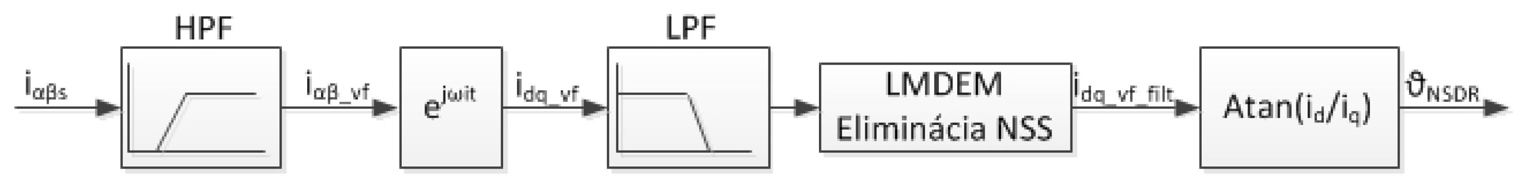
As can be seen from Equation (9), the resulting high-frequency current consists of two components mutually rotating at a different speed and in the opposite direction. The first component is directly proportional to the mean value of the stator inductance Ls. It expresses the value of the current that would flow through the stator winding if an asynchronous motor without the influence of magnetic asymmetries were considered. The given component does not contain any information about the location of the asymmetries sought. On the contrary, the second component of this high-frequency current, which rotates in the opposite direction to the voltage vector of the high-frequency excitation signal, carries information about the position of the asymmetry sought. It is proportional to the difference between the maximum and minimum change in the inductance L1 due to the effect of the motor’s magnetic asymmetries. Hence, both components must be separated, and the component that does not contain information about the location of the given asymmetry must be suppressed [
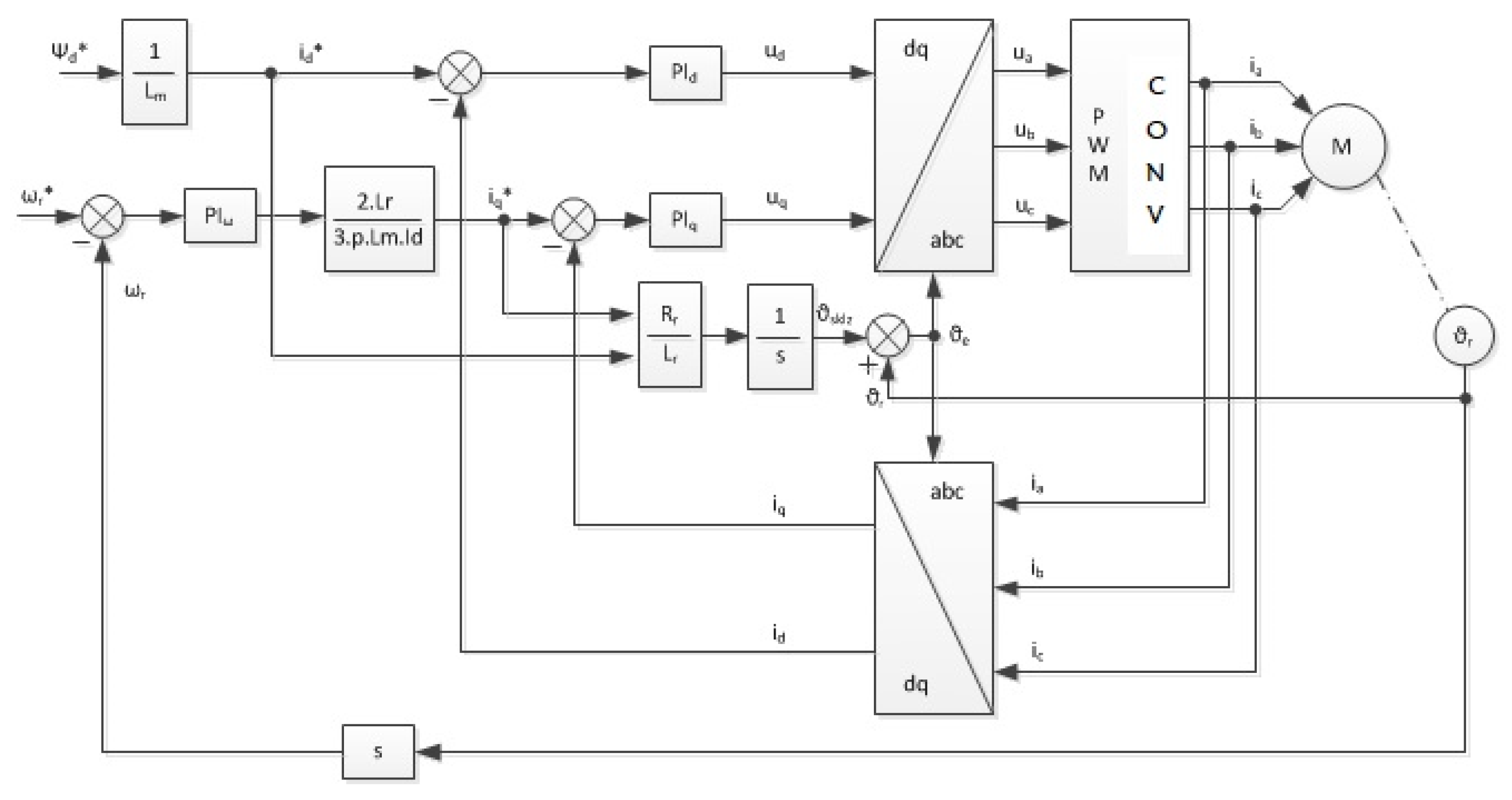
24], as shown by the block diagram in
Figure 7.
As mentioned above, the external signal is injected in the αβ system with a frequency of 1000 Hz and an amplitude of 2 V in the opposite direction of rotation as a space vector of the stator magnetic field. When opting for this signal, it is necessary to bear in mind that the high-frequency signal should not affect the function of the machine by its amplitude and frequency. Resulting from the principle of this method, the response of this high-frequency signal from the stator currents in the αβ system connected to the stator was measured (
Figure 8).
Figure 9 shows the amplitude modulation of the high-frequency signal caused by the change in the stator inductance due to the NSDR. Subsequently, it is necessary to filter out the positive component with a high-pass filter and to transform the position signal by a suitable mathematical operation into a system of injected signals rotating at speed ω
i (Equation (13)) in which we can detect changes in the stator inductance due to NSDR and thereafter determine the rotor position from the measured signal.
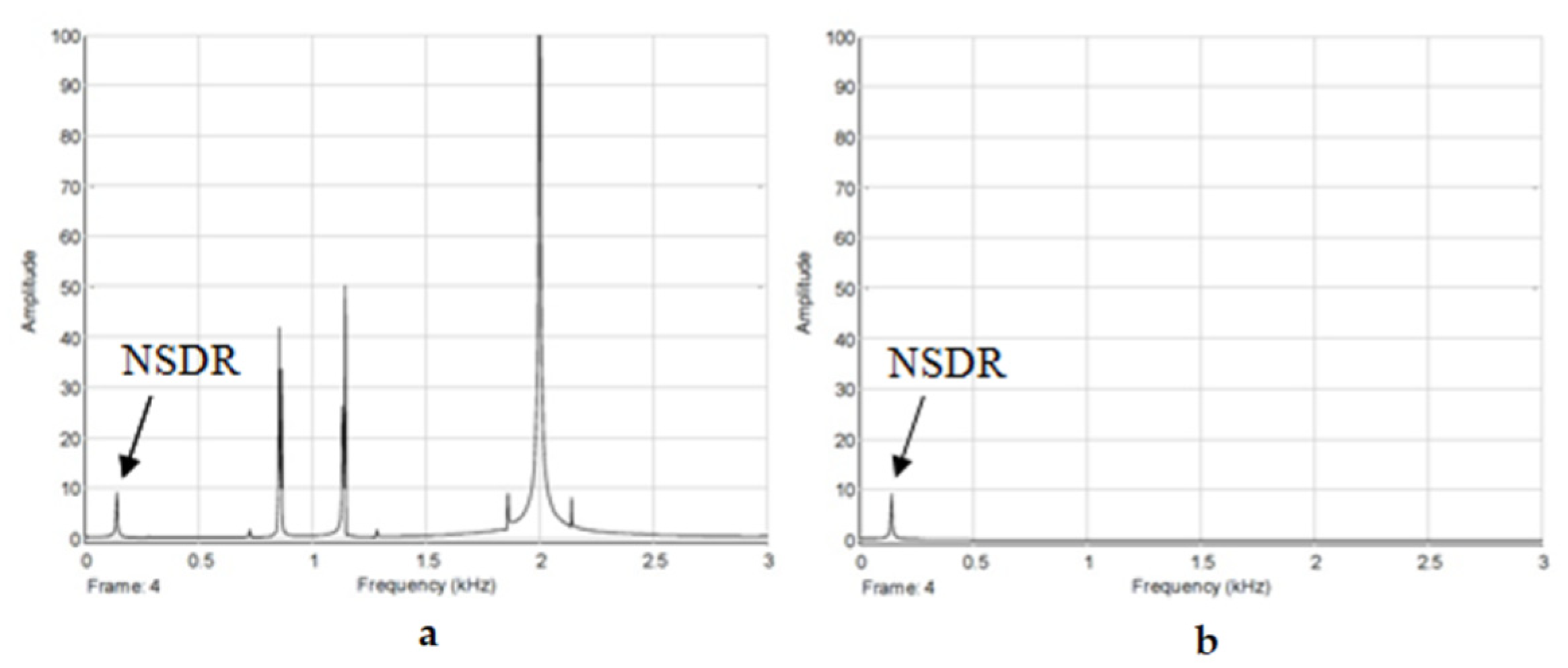
5. Asymmetry Detection Due to Rotor Slotting
Via the frequency analysis of the position signal p
d,p
q it was discovered that the measured signal consists of several signals, and one of them carries information about the rotor position, as shown in
Figure 10. It is possible to obtain a signal that describes the change in inductance LS due to RSH by including a low-pass filter (to filter out interfering signals) [
25], which are shown graphically in
Figure 11.
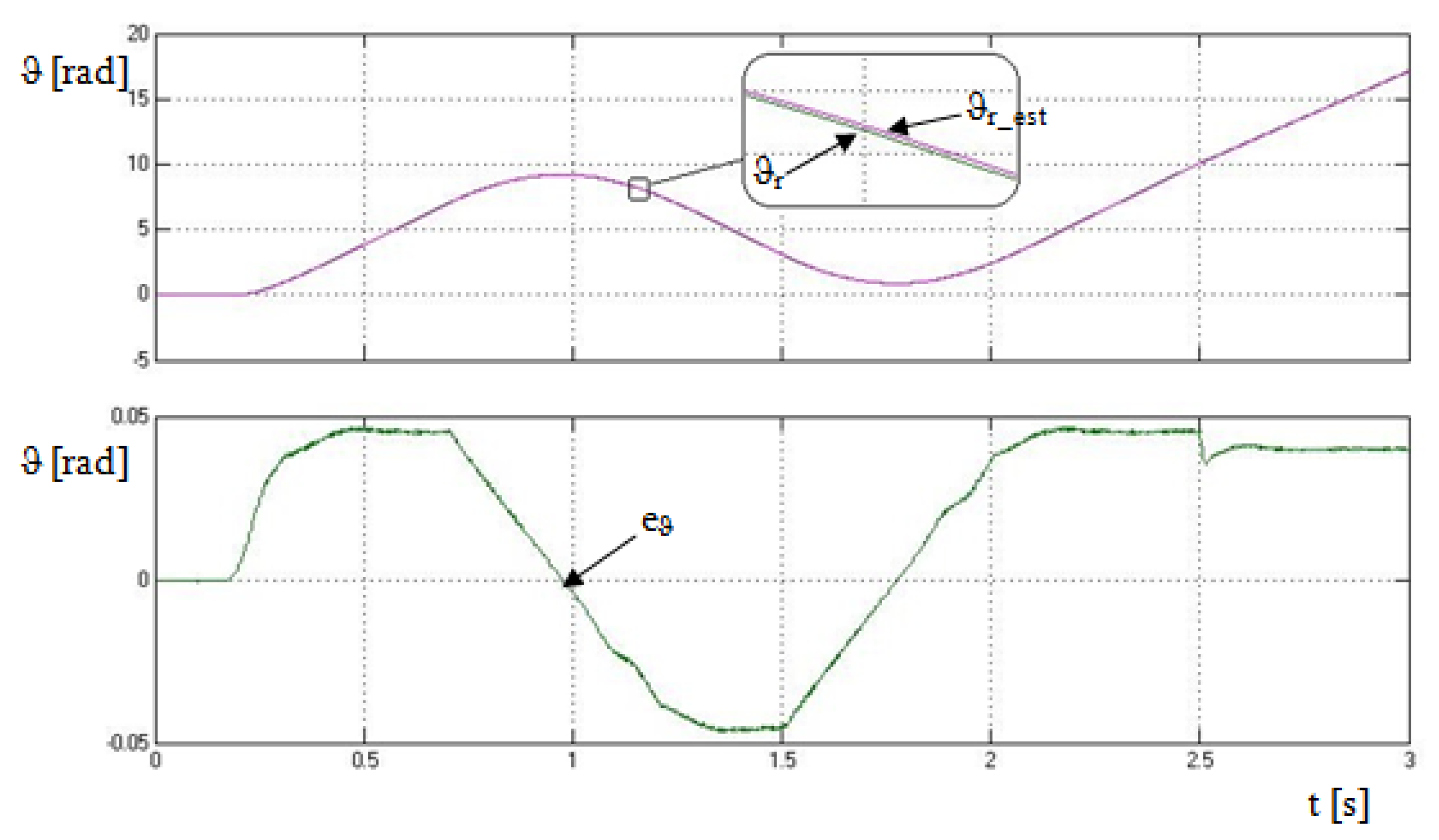
Subsequently, it is possible to calculate the estimated rotor position from this signal using the function tan
−1 (Equation (14)). The estimated position, along with the actual rotor position, which are shown in
Figure 12, enter the difference block by which the estimation error can be determined. One of the reasons why this error occurs is the phase shift caused by the frequency filters included in the control loop.
6. Estimation Introduction Due to the Magnetic Core Saturation
The magnetic asymmetry caused by the saturation of the magnetic core essentially appears in all types of machines (
Figure 13). As the title implies, it is a certain asymmetry or a deformation of the magnetic field caused by the influence of the magnetization curve non-linearity of the given material. It is because, in the design of the machines, the nominal working point of a machine is placed on the magnetization curve at the beginning of the non-linear area due to the most efficient use of a machine at the lowest weight in terms of its performance. The design of the machine structure is complex in order to avoid the magnetic circuit of the motor from becoming saturated during normal operation; however, there are places, such as the rotor and stator teeth, where the magnetic paths are narrower and more saturated due to slotting. This effect causes, inter alia, a change in the stator inductance at the saturation point.
There are two types of prevailing asymmetries that appear in the normal operation of an asynchronous motor without inclined rotor slots, as it was discovered by the frequency analysis of the measured response of an injected high-frequency signal applied to a real drive [
25]. The first type was the second and fourth harmonic of a machine operating frequencies with approximately equal amplitudes. However, their amplitude changed in direct proportion to the engine load. The second type of asymmetry represented a higher frequency asymmetry that was directly proportional to the multiple of the rotor rotation frequency and the number of rotor teeth.
Based on these findings, it was possible to create a mathematical model (Equation (15)) for such asymmetries. Moreover, when talking about the asymmetry caused by the magnetic core saturation, it must not be forgotten that this effect is not only proportional to the frequencies of the working signal, but the amplitude is also dependent on the amplitude of the stator current. All these aspects must be included in the simulation in order to get as close as possible to the real characteristics of an asynchronous motor.
After the subsequent addition of the given asymmetries to a constant value of the stator inductance, we get the course of the inductance (
Figure 14) whose value changes over time and depends on the following quantities:
- (a)
Rotor position ϑr;
- (b)
Position of the stator voltage space vector—second and fourth-order harmonics;
- (c)
Stator current amplitude.
The mathematical model of an asynchronous motor for stator voltages with these asymmetries included will have the following form:
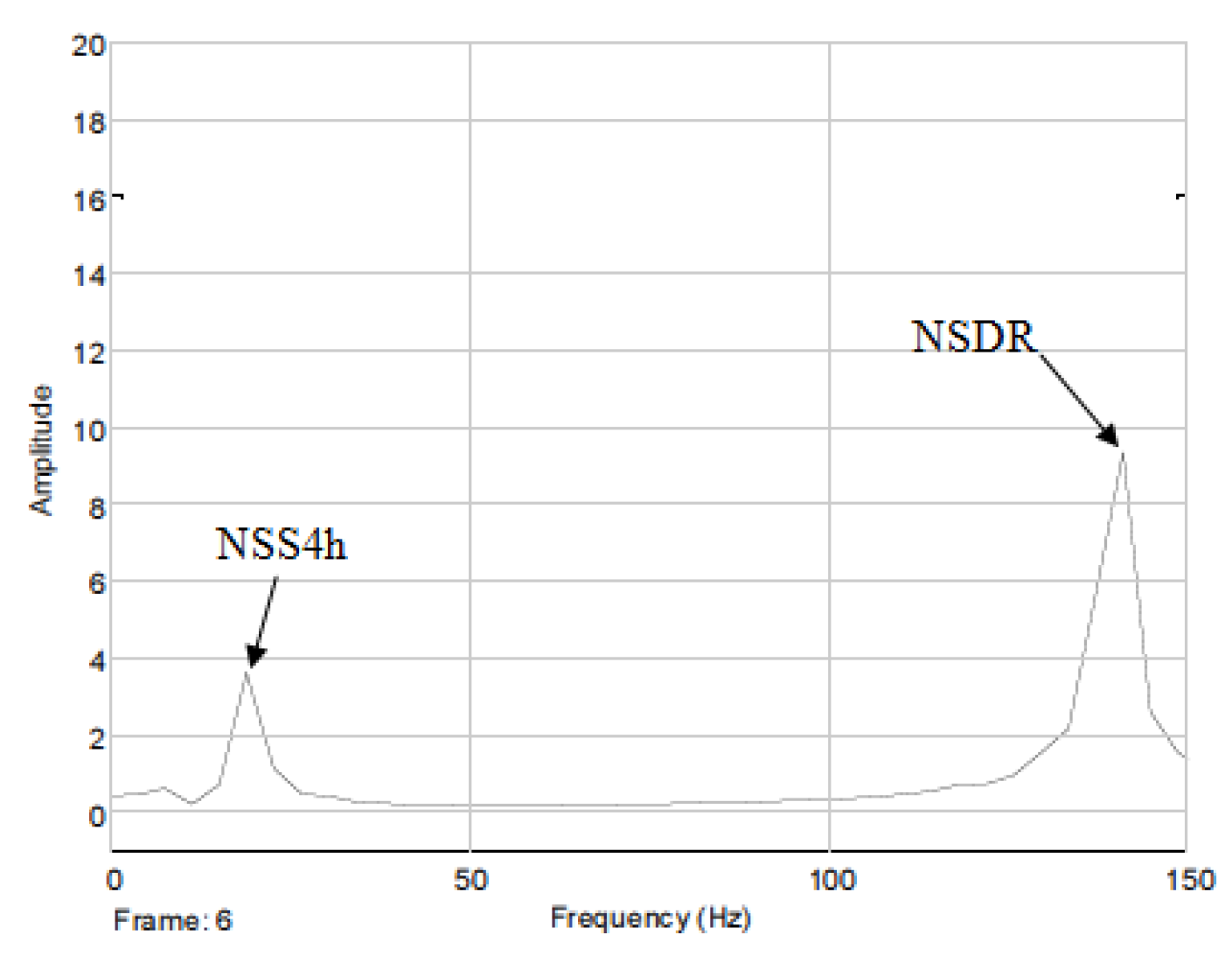
The following four components were detected by the Fourier analysis of the frequency spectrum (
Figure 15) of the machine stator inductance at the working frequency of 5 Hz. The first component was a unidirectional quantity clearly exceeding the amplitude. It represents the mean value of the machine stator inductance LS.
Other components are alternating quantities; however, the first two of them are almost identical in amplitude. They represent a change in inductance due to the NSS influence. Since they are the second and fourth order harmonics, their frequencies are 10 and 20 Hz, shown in
Figure 16. The last, fourth component represents the asymmetry created by the rotor slotting. As already mentioned, its working frequency is directly proportional to the multiple of the rotor rotation frequency and the number of rotor teeth. Thus, the frequency of this inductance change also changes with the motor load.
7. Process of Asymmetry Elimination Due to Saturation
A process similar to the one in
Section 6 will be used to estimate the rotor position. The problem is that the transformed high-frequency signal now carries information not only about the position of the NSDR but also about the position of the NSS. Thus, these introduce great inaccuracy into the rotor position estimation (
Figure 17) mainly because they also depend on the stator current amplitude.
It is necessary to eliminate the asymmetry of the NSS using one of the methods mentioned above. As mentioned, there are several methods for adverse harmonics elimination. However, the LMDEM method has been chosen for the purpose of this work. It is based on the gradual elimination of asymmetries caused by saturation up to the point when they are minimized to a value in which they have minimal or no disturbing influence on the rotor position estimation.
The Fourier analysis was used to determine the frequency spectrum of the measured signal at the machine’s working frequency of 5 Hz. When compared with the frequency analysis of the machine inductance, it can be seen that this signal contains information only about asymmetries without a unidirectional component (
Figure 18).
Since the asymmetries that need to be eliminated are only the higher harmonics of the machine’s operating frequency, the measured signal can be firstly transformed (Equation (16)) into a system rotating at twice the frequency of the stator voltage.
With the transformation, it can be achieved that the monitored asymmetry will now be a unidirectional quantity and the alternating components are the fourth harmonic asymmetry now with a frequency of 10 Hz and the NSDR asymmetry. It is necessary to use a low-pass filter to filter out all alternating components by setting the filter to a low frequency (<1 Hz) in order to eliminate this unidirectional component. Subsequently, this asymmetry is dependent on the amplitude of the stator current; hence, it is necessary to calculate the relative value of these two quantities Apd, Apq and write these values in a table.
These two components are stored in the memory and subsequently read when the drive is started depending on the stator current amplitude measurement. A value is obtained by multiplying the amplitude of the stator voltage and the proportional quantity. If the given value is subtracted from the transformed position signal and the unidirectional component is removed, it represents the asymmetry position. The elimination of the second-order NSS asymmetry (
Figure 19) is successful after removing this unidirectional component and reverse transformation.
The measured signal contains only two types of asymmetry. Thus the asymmetry is caused by fourth-order saturation and NSDR. The NSS of the fourth order can also be eliminated in a similar way, hence with the difference that the transformation will be made into a system rotating at four times the speed when compared with the stator rotating field system (Equation (17)).
The asymmetry eliminating procedure from the measured signal is essentially the same as in case of eliminating the second harmonic. A measured signal with essentially already minimized NSS asymmetries is obtained after the reverse transformation. Thus the measured signal waveforms (
Figure 20) and the frequency analysis (
Figure 21) prior to and after the elimination of those asymmetries.
Since the measured signal now no longer contains serious disturbing harmonics NSS but only information about the rotor position, the rotor asymmetry position can be calculated from the measured signal via the tan
−1 function that is as many times larger as the number of rotor teeth (
Figure 22).
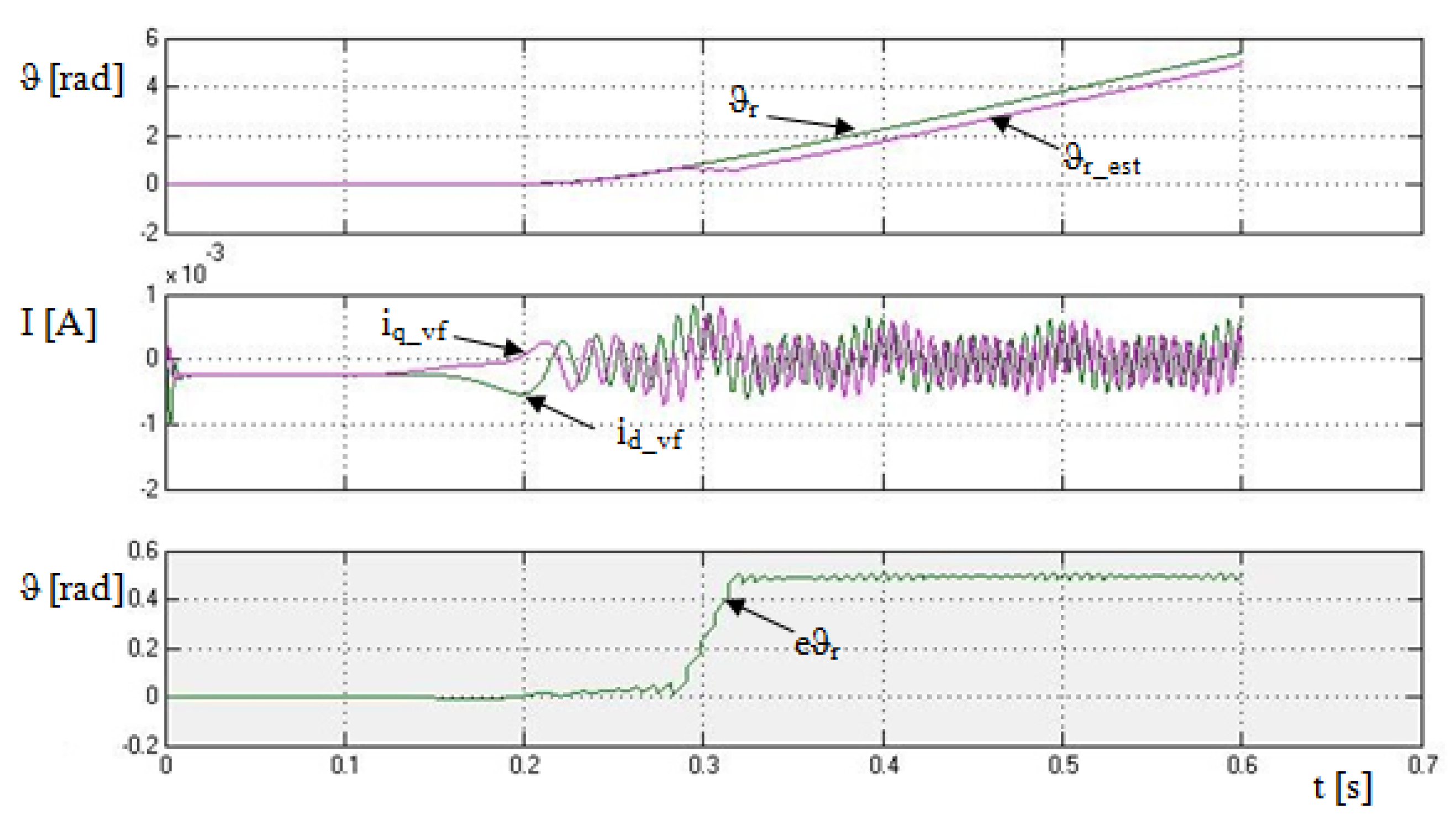
The estimation error did not exceed 0.05 rad (
Figure 23), that was achieved by this elimination of NSS, just as in the estimation when only the asymmetry caused by the rotor slotting was introduced.
8. Different Modes—Starting, Reversing, Engine Load
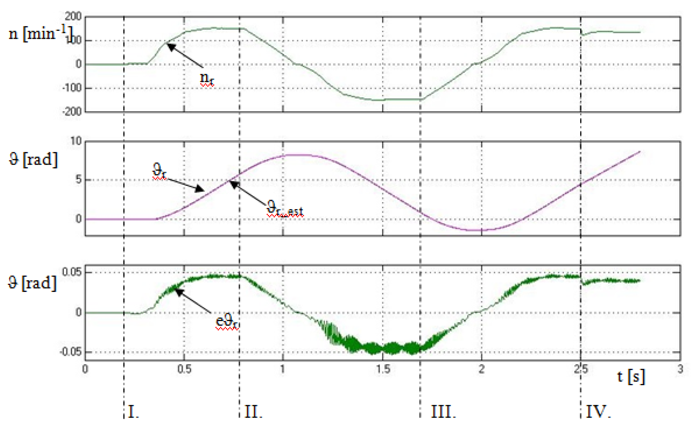
After eliminating the asymmetry that does not carry any information about the rotor position, the quality of the rotor position estimation can be verified in different drive modes such as start-up, reversal, back-reversal, and engine load. The drive again worked in scalar control mode.
In the first interval from the left, the motor is at time t = 0.2 s on the ramp started up in 0.3 s with the stator voltage frequency of 5 Hz. As can be seen in
Figure 24, the first course shows the course of the engine speed, followed by the course of the real and estimated rotor position, and the last course shows the estimation error, as well as the difference between the real and estimated rotor position.
The second interval of 0.8–1.3 s shows the reversal of the engine speed. The estimation error in this interval is noisier than in the previous one; however, the error of 0.05 rad was not exceeded.
The third interval starts at time t = 1.7 s and shows a reversal to the engine speed value of 150 min−1. It can also be seen that the estimation took place during the reverse reversal without any problems, and the instantaneous value of the estimation error was stabilized after the stabilization of the engine speed with an oscillation around a constant value without exceeding the error of 0.05 rad again.
The first, second, and third intervals showed the estimation reliability at revolutions up to 5 Hz in both directions without any engine load. The last interval shows the rotor position estimation at a motor load of 10% of the rated torque. The speed after loading a motor with a certain load decreases due to the nature of asynchronous motors. The rotor position estimation worked without issues even in this case; moreover, the estimation error decreased by about 0.005 rad after the loading.
As can be seen from the estimation quality curves, the estimation error generally increased with the increasing machine speed. After the engine speed was stabilized, the instantaneous value of the estimation error fluctuated around a constant value.
9. Conclusions
The sensorless method for the rotor position estimation of an asynchronous motor entitled INFORM was verified by simulation in the present research work. The subchapters gradually clarified how two types of magnetic asymmetries occur during operation in asynchronous motors and affect the instantaneous value of the stator inductance LS. These types of asymmetry were included in the mathematical model of the asynchronous motor. The given asymmetries were subsequently detected by the method of injecting the high-frequency signal in the αβ system with the frequency of 1 kHz and the amplitude of 2 V.
The asymmetries caused by the magnetic circuit saturation created a distortion of the measured signal; hence, it was necessary to identify and subsequently eliminate them. The LMDEM method was successfully used as an elimination method to suppress these asymmetries. The signal, which only contained information about the asymmetry position caused by the rotor slotting, was recalculated to the rotor position using the arctan function and subsequent multiplication by the number of rotor teeth.
The simulation of the asynchronous motor control using the scalar control method was created based on the aforementioned knowledge and mathematical models. The verification by simulation took place in different modes, i.e., starting, reversing, and loading the drive with 10% rated torque. As can be evaluated from
Figure 23, with the drive starting at the frequency of 5 Hz, the difference between the real and estimated position was, at most, 0.05 rad. This deviation was 5 Hz during the entire time of the rotor rotation. Thus it was constant.
The graphic process in
Figure 24 compares the different operating modes already mentioned above. The deviation of the estimated and real position of the rotor obtained via the INFORM method is clearly dependent on the speed of the rotor rotation according to these intervals. As the speed increases, the position estimation error also increases. This error at the rotation speed of 5 Hz did not exceed the deviation values of 0.05 rad.
It is necessary to build powerful hardware for the most accurate control in order to ensure the lowest possible deviation between the real and estimated rotor position, as was found out during simulations. An engine design with straight rotor slots with the most significant asymmetries would also be necessary to subsequently compare it with a conventional motor with inclined slots.


