Article

A Pneumatic Control Method for Commercial Vehicle Electronic Brake System Based on EPV Module

1
School of Mechanical and Automotive Engineering, Liaocheng University, Liaocheng 252000, China
2
Liaocheng Transportation Service Center, Liaocheng 252000, China
*
Author to whom correspondence should be addressed.
Actuators 2022, 11(11), 316; https://doi.org/10.3390/act11110316
Submission received: 23 September 2022 / Revised: 27 October 2022 / Accepted: 28 October 2022 / Published: 31 October 2022
(This article belongs to the Section Actuators for Surface Vehicles)

Abstract

:
The traditional electronic braking system (EBS) of a commercial vehicle has the problems of sluggish pressure response, large dynamic error and unsatisfactory braking effect during braking. First, a novel EBS system based on electronic pneumatic valves (EPV) module is designed, which integrated the control of each pneumatic valve. Secondly, the hardware of the EBS bottom controller and the air pressure closed-loop control are carried out. A kind of similar to PWM (SPWM) air pressure control method is proposed. By controlling the opening and closing time of the solenoid valves, the brake air pressure could be precisely regulated, and the dynamic response characteristics of the system are improved. Eventually, commercial vehicle air brake hardware in the loop (HIL) test platform based on LabVIEW and NI-PXI system is built to verify the effectiveness of the EBS dynamic response characteristics. The experimental results showed that the continuous control of EBS solenoid valves is realized by using the SPWM control method, and the fine dynamic response characteristics of EBS air pressure closed-loop control are ensured.

1. Introduction

As the main force of road transportation, commercial vehicles play an important role in the transportation system. In particular, China’s commercial vehicle market occupies a global leading edge in terms of scale and status, and it has always maintained a healthy and prosperous development trend, as shown in Figure 1. In 2020, the annual production and sales of commercial vehicles in China exceeded the 5 million mark. Although the commercial vehicle market is booming, the problem of road traffic safety is always the pain point for commercial vehicles. The death rate and diameter economic loss of commercial vehicle road traffic accidents account for the largest proportion in the whole road traffic accidents. According to the analysis of Euro NCAP, in the braking process of commercial vehicles, 90% of the braking deceleration value is less than 0.25 g, and most traffic accidents are caused by braking. Autonomous emergency braking (AEB) technology can reduce 38% of rear-end collision accidents in the real world, and it can avoid 80% of collision accidents when the speed does not exceed 20 km/h. Therefore, since November 2013, the European Union (EU) has stipulated that commercial vehicles must be equipped with AEB system according to laws and regulations. In 2014, Euro NCAP officially included AEB in the bonus item of new vehicle safety evaluation. China also followed the successful experience and required that commuter buses more than 9 m must be equipped with AEB system from 1 April 2019. Under the background of safety oriented, many scientific research institutions and automobile manufacturers pay more attention to the research on the service braking safety of commercial vehicles.
However, the mechanical pneumatic braking system carried on commercial vehicles has the problems of sluggish pressure response and low air pressure control accuracy, which is difficult to meet the needs of more intelligent and safer commercial vehicle braking system [1]. Therefore, the pneumatic EBS using mechanical pneumatic electronic control combined components came into being. EBS system can realize linear continuous adjustment of braking pressure and ideal braking force distribution. It is the basic executive technology of commercial vehicles automatic driving technology [2].
The bottom working logic of the EBS is the process of converting the stroke of the brake pedal into an electric signal; combining the wheel speed and road surface information, the ECU calculates the required braking force under the current state, and then controls the actuator to generate the braking force on the wheel [3]. The system can combine relevant algorithms to improve control accuracy, shorten response delay time and ensure safety redundancy [4]. At present, the research on the pneumatic braking system of commercial vehicles is mainly based on the dynamic characteristics of the system based on ABS, ESC and other algorithms [5]. However, due to the sluggish pressure response and poor control accuracy in the braking process of commercial vehicles, the ideal braking effect cannot be achieved [6].
In order to realize the accurate control of the brake air pressure, the key lies in the model and control of commercial vehicles pressure valve block [7]. Subject to the complex connection of commercial vehicles air circuit and the joint action of multiple physical fields, the model and control of pressure valve block have always been a difficult problem in the design and application of wire controlled pneumatic braking system [8], and many scholars have made beneficial exploration in this field.
In view of the dynamic response characteristics of the pneumatic braking system, Day Andrew J. et al. built the main components simulation models of the passenger car pneumatic braking system such as the brake pedal and the brake chamber in AMESim, simulated and tested the dynamic response characteristics of the brake pedal, and improved the response characteristics of the system [9]. Ma Tianfei and Qian Chen conducted model and simulation tests on foot valve, brake chamber and relay valve, and studied the dynamic response characteristics of the system in AMESim [10].
Be directed against the different valves dynamic models of the pressure building process Rager David et al. proposed the second-order approximate mode of one-dimensional linear resistance compressible model to describe the flow phenomenon of the brake air in the pneumatic controller tube [11]. Based on the open-loop control of the high-speed switch solenoid valve, Lv Chen et al. proposed an open-loop load pressure control theory under the valve critical open balance state, which solved the problems of high precision and fast response of the hydraulic control of the automotive braking system [12]. Breidi Farid et al. improved the dynamic performance and response time of the on-off valve by changing the electrical signal input of the solenoid valve, improved the control efficiency and made the valve control more accurate [13]. Richer Edmond and Yildirim Hurmuzlu studied the nonlinear flow characteristics of gas through the proportional valve to control the valve, as well as the influence of time delay and attenuation in the pneumatic pipeline, and proposed the nonlinear force controller [14]. Han Jong Chol et al. developed a simulation tool for proportional relay valve of commercial vehicle pneumatic EBS using MATLAB/Simulink environment, which can be used for hardware and control algorithm development of pneumatic EBS for commercial vehicles [15].
According to different structures and demands of commercial vehicles, Miller Jonathan I. et al. embedded solenoid valve in the brake chamber, which significantly reduced the hysteresis time and the number of components of the pneumatic control system [6]. Cheon Jae Seung et al. in Hyundai introduced a wire controlled braking system combining electronic wedge brake (EWB) and electronic mechanical braking (EMB), which greatly simplified the pipeline connection and realized the configurable form of wire controlled braking system [16]. H. Barlsen et al. in WABCO cooperated with the traditional pneumatic braking system controlled by the solenoid valve and relay valve, and realized the braking by wire function of the trailer on the framework of the original pneumatic line control system of the commercial vehicle [17]. Bao Hanwei et al. proposed four structural configurations for the automatic pressure regulating valve (APRV) to meet the requirements of the Electronically Controlled Pneumatic Brake system (ECPBS) and took the APRV as the research object studied the pressure change rate during the braking process [4]. The mathematical model based on gas dynamics and the association model between pressure change rate and vehicle dynamic model is established in MATLAB/Simulink; through the experimental test, the key structure parameters affecting the pressure change rate of the automatic pressure regulating valve and the influence law have been identified [7].
Aiming at the dynamic response characteristics of the pneumatic braking system of commercial vehicles, Lei Ming et al. built a dynamic model for the ABS relay valve, and analyzed the effects of voltage, coil, resistance and other factors on its dynamic characteristics based on Simulink model; moreover, they developed the test software for the ABS relay valve [18]. Li Yanting carried out dynamic model of the ABS valve, built Simulink model and HIL test platform, and conducted HIL test on the dynamic response characteristics of the ABS valve [19]. Shi Yan et al. used AMESim to model the foot valve, obtained the structural parameters of each component by disassembling the valve body, analyzed the impact of each parameter on the dynamic response of the system, and then verified the accuracy of the model by building a test platform [20]. An Zhimin studied the static characteristics of the relay valve, built its dynamic model with Matlab and AMESim for co-simulation and, on this basis, designed and developed the test platform for the dynamic characteristics of the relay valve [21]. Zong Changfu has established a mathematical model of proportional relay valve that can reflect the hysteresis response characteristics, and verified the accuracy and reliability of the model by using the inverse hysteresis feed-forward compensation and PID closed-loop control method [22].
For the selection of the solenoid valve control method, Zhang Bin et al. found that the response time of valve is directly affected by three factors: control signal, operating frequency of the on–off valve and pressure in the control room [23]. Chen Hui controlled the proportional relay valve in the form of a combination of current loop and air pressure loop to achieve accurate regulation for brake air pressure [24]. M. You et al. established the mathematic model for proportional relay valve in Matlab/Simulink and verified through open loop experiment. A PI controller with feed-forward and anti-windup compensation is designed, which could improve the pressure regulation precision and robustness [25]. Zheng Hongyu et al. proposed a control method with a three-layer hierarchical structure considering structure characteristics of electronic pneumatic braking system. The experiment results showed that the control method could improve the braking performance of a vehicle [26]. Wan, Y. et al. presented a hysteresis compensation control method that integrated a PID closed loop control and the feed-forward compensation control for mitigating the hysteresis characteristic of proportional relay valve and improving the pressure response character of the front wheels [27].
To solve the problem of linear pressure control of high-speed switch solenoid valve, Kong Xiangdong proposed a pressurization control mode to realize linear pressurization of gas flow output. At the same time, the rules that the switching characteristics of the electromagnetic reversing cartridge valve are affected by the stiffness of the main valve, fluid resistance, system pressure, etc. [28]. Bali, E. and E. Erzan Topcu designed a solenoid valve which is the on-off type solenoid in electronically controlled pneumatic brake systems, and its static characteristics have been investigated theoretically [29].
The most critical technology of the brake-by-wire (BBW) is a safe and redundant system design and precise air pressure control method, which is also the main research goal of this paper. The research team in this article has made some achievements in the field of steering-by-wire (SBW) [30,31,32,33], and they provided the research basis and conditions for this article.
To solve the practical problems of slow pressure response, large dynamic error and unsatisfactory braking effect in the braking process of the commercial vehicle electronic braking system, a novel commercial vehicle EBS system based on the electronic pneumatic valve (EPV) module is designed firstly in this paper. Secondly, by analyzing the dynamic characteristics of the EPV module, the key components dynamic models are established. Then, based on the dynamic models, the bottom controller and air pressure closed-loop control logic of EBS are designed, and a new similar to PWM (SPWM) air pressure control method is proposed to realize the precise adjustment of the air pressure controlled by EPV. Finally, a commercial vehicle pneumatic brake hardware in-loop test bench based on LabVIEW and NI PXI system is built to verify the dynamic response characteristics of the designed EBS system.
Compared with previous studies, the main contributions of this study are as follows:
(1)
A novel EBS system based on the EPV module is designed by integrating various pneumatic valves, which improves the structure layout of the system and optimizes the precision of pressure regulation.
(2)
A novel SPWM air pressure control method is proposed to achieve different pressure-increasing and decompressing speeds by controlling the duration of the pressure-increasing and decompressing states of the valve in one cycle.
The study is arranged as follows: the structure design of commercial vehicle EBS based on the EPV module is carried out in Section 2. The dynamic model of the EPV module is carried out in Section 3. The commercial vehicle EBS bottom controller based on the EPV module is designed in Section 4. The dynamic response of air pressure closed-loop control of EBS bottom controller based on the EPV module is verified in Section 5.

2. Structure Design of Commercial Vehicle EBS Based on the EPV Module

At present, the pneumatic EBS of commercial vehicle mainly includes ECU controller, high-pressure air tanks, front axle and rear axle proportional relay valves, brakes, ABS valves, brake air chambers, pressure sensors and other parts. Compared with the traditional pneumatic ABS system, the system mainly increases the proportional relay valves with the functions of active pressurization and standby pressure so as to achieve the purposes of BBW, active pressurization and safety redundancy.
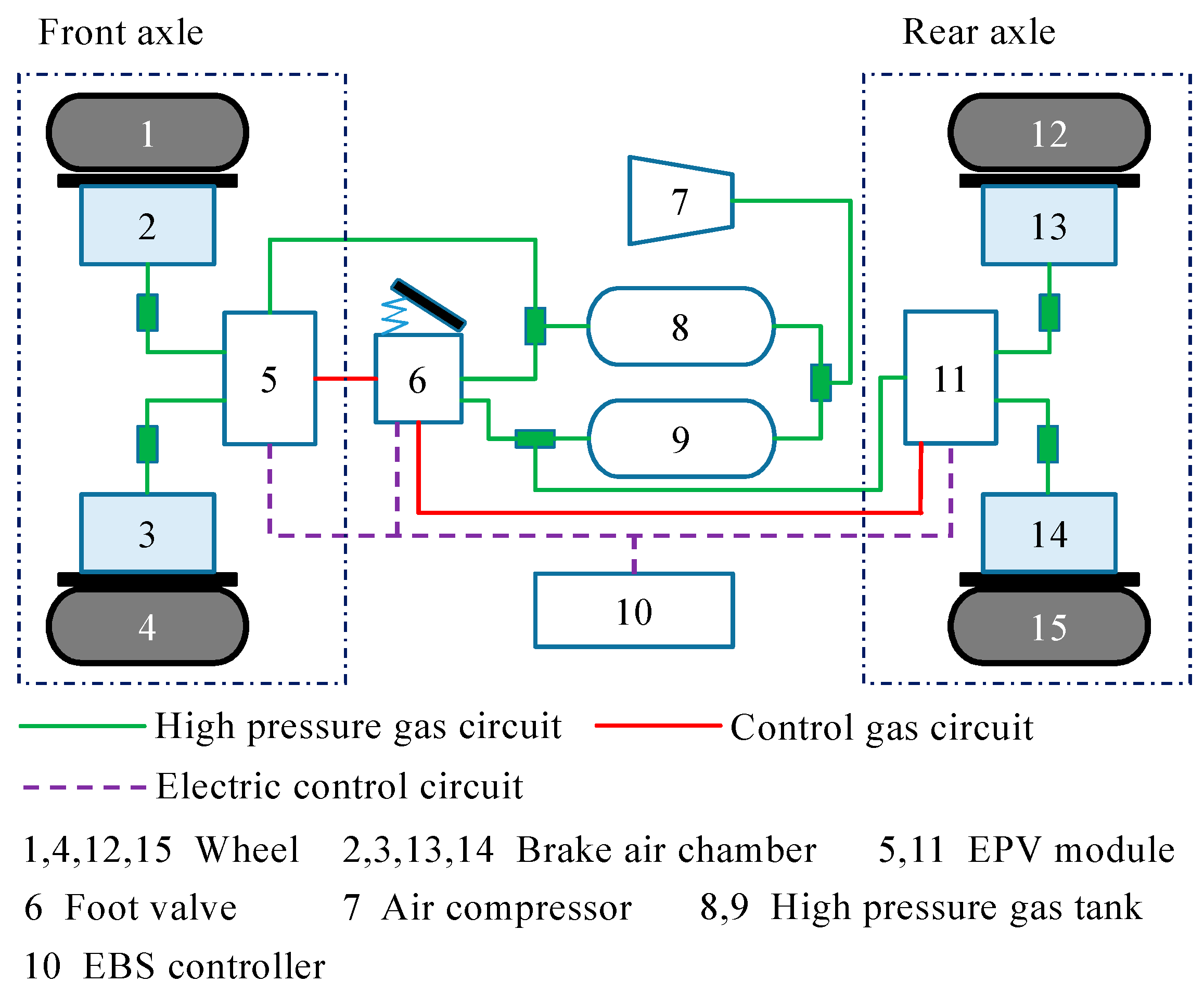
Although the proportional relay valve is an integrated air pressure control valve, it integrates the functions of the active booster valve and the relay valve, which can not only realize the active booster but also ensure the safety redundancy. However, the foot valve and the front and rear brake chambers must be connected by a long pipeline. In addition, the strong compressibility of the gas will inevitably lead to the problems of slow pressure response, serious pressure hysteresis and poor dynamic response of the pneumatic braking system, which will affect the working performance of the pneumatic EBS and the active safety of commercial vehicles. In order to further optimize the dynamic response characteristics of commercial vehicle pneumatic EBS, manuscript integrated the four main pneumatic valves of the pneumatic braking system, including the active booster valve, the standby pressure valve, the relay valve and the ABS valve, which is called the EPV module. In this way, the EBS structural layout and schematic diagram based on the EPV module is shown in Figure 2.
Compared with the EBS system based on ABS, the proportional relay valve is replaced by the relay valve in the EPV module and adds a standby pressure valve. The structural layout of the EPV module is more reasonable. By placing a booster valve and a relief valve in front of the relay valve, the regulation of small flow control air could be realized, and then, through the linear amplification of the relay valve, the control air entered the brake air chamber, so the accuracy of air pressure control would be higher. This mode not only realized the wire control adjustment of the brake air pressure but also ensured that the mechanical brake backup could be retained in case of failure of the electric control system, so as to ensure safety redundancy.
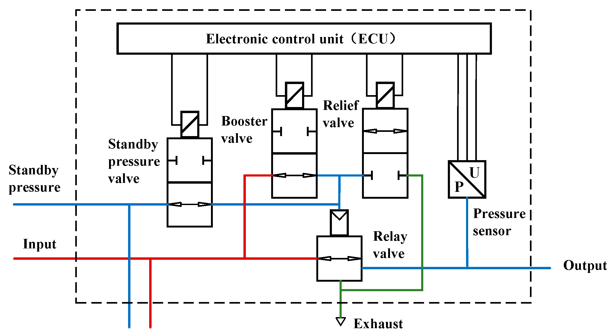
The schematic diagram of the air pressure valve controlled by wire of the EPV module is shown in Figure 3. This module included the electronic control unit (ECU), U/P pressure sensors, standby pressure valve, booster valve, relief valve and relay valve. The wheel speed, brake wear and other signals are collected by ECU, and the braking signal sent by the EBS controller is transmitted to the EPV module through the CAN-bus to generate braking pressure and regulate the braking pressure. At the same time, the pressure sensors transmit the actual pressure generated by the brake chamber back to the EBS controller via CAN-bus.
Each air pressure control channel of the EPV module is equipped with four ports—namely, the standby pressure port, the input port, the output port and the exhaust port. The input port is connected to the high-pressure air tank, the standby pressure port is connected to the foot valve, the output port is connected to the brake air chamber and the exhaust port is connected to the atmosphere. Under normal conditions, the driver applied pressure to the brake pedal to generate a braking signal, close to the standby pressure valve and cut off the control air pressure from the brake pedal. The EBS controller controlled the opening and closing states of the booster valve and the relief valve according to the travel of the foot valve, so that the generated brake air pressure is linear with the travel of the brake pedal. When the electric control fails, the standby pressure valve continued opening, and the output port is connected with the input port. The brake air from the foot valve directly entered the brake air chamber through the foot valve to generate the braking force. Even if the electric control is invalid, there is still mechanical braking backup, which achieved the purpose of safety redundancy.

3. Dynamic Model of the EPV Module

3.1. Characteristics Analysis of the EPV Module

The schematic diagram of the EPV dynamic characteristic analysis is shown in Figure 4. The system can be divided into three parts: pressure source, air pressure control module and brake. The pressure source included the air compressor and high-pressure air tank. It is assumed that the pressure p0 will not change during a braking process. The air pressure control module is composed of booster valve, relief valve and relay valve. The control air from the booster valve or relief valve pushed the piston downward. After cutting off the exhaust port, it contacted the bottom piston and continued to move downward together against the spring preload and then opened the air inlet to fill the brake air chamber with high-pressure air. In this module, A1 is the effective area of the upper piston, p1 and V1 are the pressure and volume of the control air chamber, respectively, ma1 is the gas mass in the control air chamber, m1 and m2 are the upper and bottom piston masses, respectively, k1 is the bottom spring stiffness coefficient and x1 is the downward displacement of the bottom piston. The brake is composed of a brake air chamber and a brake piston. Driven by compressed gas, the brake piston overcame the preload of the return spring and moved forward to generate braking force. In this module, A2 is the effective area of the brake piston, p2 and V2 are the pressure and volume of the brake air chamber, respectively, ma2 is the gas mass in the brake air chamber, m3 is the brake piston mass, k2 is the return spring stiffness coefficient, x2 is the displacement of the brake piston and F is the reaction force of the friction plate to brake piston.

3.2. Dynamics Model of the EPV Module

In order to establish the dynamic models that meet the engineering requirements, the following assumptions are made in this manuscript. (1) The gas is an ideal gas, and the process is an adiabatic process. (2) The air inlet and exhaust ports of the pneumatic valves are well-sealed without gas leakage. (3) Ignoring the gravity of valve body parts. (4) Ignoring the friction between friction pairs.
During braking, the state equation of the gas in the control air chamber can be described as Equation (1), where z is the adiabatic coefficient and C is a constant; for air, z = 1.4.
p 1 V 1 m a 1 z = C
Equation (2) can be obtained by deriving time t from Equation (1).
d p 1 d t = z p 1 m a 1 d V 1 d t + z p 1 V 1 d m a 1 d t
The gas mass is derived from the time t to obtain the gas mass flow, which is related to the pressure of the air source, the pressure of the control air chamber, the pore size of the booster valve and the relief valve, as shown in Equation (3).
q m a 1 = d m a 1 d t = c d p 0 D 2 z + 1 1 z 1 2 z T a R a z + 1 1 2 ,   D 0       a n d       p 1 p 0 0.518 c d p 0 D z p 1 / p 0 2 z p 1 / p 0 z + 1 z T a R a z 1 / 2 1 2 ,   D 0       a n d       p 1 p 0 > 0.518 c d p 1 D 2 z + 1 1 z 1 2 z T a R a z + 1 1 2 ,   D < 0       a n d       p a p 1 0.518 c d p 1 D z p a / p 1 2 z p a / p 1 z + 1 z T a R a z 1 / 2 1 2 ,   D < 0       a n d       p a p 1 > 0.518
In Equation (3), qma1 is the gas mass flow of control air chamber, cd is the pore flow coefficient of gas, pa is the atmospheric pressure, D is the effective diameter when the solenoid valve is open, Ta is the Kelvin temperature of ideal gas and Ra is the ideal gas constant.
Under the driving of the control air pressure the dynamic equation of the downward movement process of the relay valve upper piston against the spring preload can be expressed as Equation (4) before and after contact with the bottom piston.
m 1 d 2 x 1 d t 2 = A 1 p 1 A 2 p 2 F f 1 ,   0 x 1 x m m 1 + m 2 d 2 x 1 d t 2 = A 1 p 1 A 2 p 2 F f 1 k 1 x 1 + x 10 ,   x m x 1 x t 1
In Equation (4), xm is the displacement when the top piston contacts the bottom piston, xt1 is the maximum displacement of top piston, x10 is the precompression stroke of bottom spring and Ff1 is the friction force on piston. Ff1 can be expressed by Equation (5), where μ is the friction coefficient and Fv is the positive pressure of piston on the valve body.
F f 1 = s i g n d x 1 d t μ F v
Similarly, the state equation of the gas in the brake air chamber is shown in Equation (6), and the gas mass flow is shown in Equation (7).
d p 2 d t = z p 2 m a 2 d V 2 d t + z p 2 V 2 d m a 2 d t
Ar is the difference in cross-sectional area between the intake and exhaust ports of relay valve. When x1 < xm, the air inlet is closed and the exhaust is open; at this time, Ar < 0. When x1 >≥ xm, the air inlet is open and the exhaust is closed; at this time, Ar ≥ 0.
q m a 2 = d m a 2 d t = c d p 0 A r 2 z + 1 1 z 1 2 z T a R a z + 1 1 2 ,   A r 0       a n d       p 2 p 0 0.518 c d p 0 A r z p 2 / p 0 2 z p 2 / p 0 z + 1 z T a R a z 1 / 2 1 2 ,   A r 0       a n d       p 2 p 0 > 0.518 c d p 2 A r 2 z + 1 1 z 1 2 z T a R a z + 1 1 2 ,   A r < 0       a n d       p a p 2 0.518 c d p 2 A r z p a / p 2 2 z p a / p 2 z + 1 z T a R a z 1 / 2 1 2 ,   A r < 0       a n d       p a p 2 > 0.518
The dynamic equation of the piston in brake air chamber can be expressed as Equation (8). In Equation (8), x20 is the precompression stroke of the return spring, xt2 is the maximum displacement of the brake piston and Ff2 is the friction force on the brake piston.
m 3 d 2 x 2 d t 2 = A 2 p 2 k 2 x 2 + x 20 F f 2 ,       0 x 2 x t 2
Ff2 can be expressed by (9).
F f 2 = s i g n d x 2 d t μ F v
Consequently, the volume of control air chamber and brake air chamber of the EPV module can be expressed as (10).
V 1 = V 10 + A 1 x 1 ,   0 x 1 x t V 2 = V 20 + A 2 x 2 A 1 x 1 ,   0 x 1 x t 1 ,   0 x 2 x t 2

4. Design of Commercial Vehicle EBS Bottom Controller Based on EPV

4.1. Hardware Architecture of Commercial Vehicle EBS Bottom Controller Based on EPV

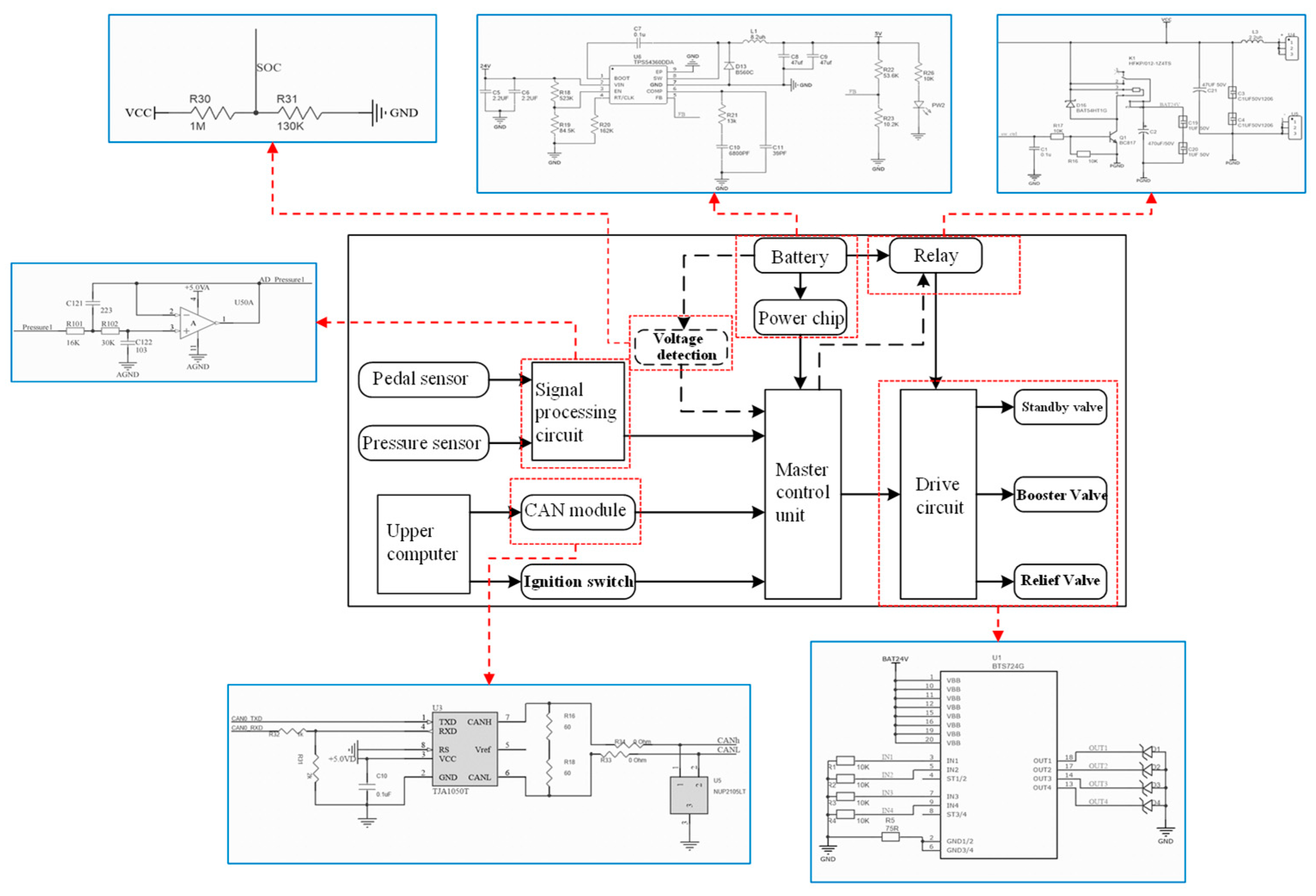
This is example 1 of an equation: According to the operating conditions of commercial vehicles and the dynamic characteristics of EBS, the bottom controller is designed in this manuscript. The logic block diagram of its hardware structure is shown in Figure 5. The controller used control circuits to obtain the pedal status and other signals through the sensors, so as to judge the driver’s demands for braking force. At the same time, it used CAN as the interface to communicate with the upper control signals. In order to ensure the safety of the circuits, the I/O ports of the control circuits are used to control the on-off of the relay, so as to realize the purpose of low-power control circuit controlling high-power drive circuit. The master control unit is MPC5744p, and it has reliable working performance to ensure that it can meet the highest level of safety function requirements (ASIL-D) for commercial vehicles and high main frequency to ensure real-time information communication and high-speed data operation. In the power supply circuit, TPS54360 and LM1117-3.3 are used as voltage-stabilizing chips of 24 V to 5 V and 5 V to 3.3 V circuits, respectively. CAN communication, as an asynchronous communication, is controlled by CAN_ High and CAN_ Low two signal lines to form a group of differential signal lines. The bus communication is carried out in the form of differential, and the TJA1050T chip is selected as the CAN transceiver. Using a high-precision operational amplifier AD8544 to build an operational amplifier circuit, triode to construct relay switch circuits, two series resistors with resistance values of 1M and 130K are connected to the ADC pin of the single chip microcomputer to design the voltage detection circuit of the battery and three Infineon BTS724G chips and freewheeling diodes to build the solenoid valve drive circuits. The external interface and relevant parameters of the controller are shown in Table 1.

4.2. Air Pressure Close-Loop Control Logic of EBS Controller Based on EPV Module

The authors should discuss the results and how they can be interpreted from the perspective of previous studies and of the working hypotheses. The findings and their implications should be discussed in the broadest context possible. Future research directions may also be highlighted. When receiving the target pressure request of the upper layer, the EPV module regulated the small flow control gas through the opening and closing of the booster valve and the relief valve, and then, the control gas entered the brake air chamber through the linear amplification of the relay valve. The working processes of pressure boosting, pressure maintaining and pressure relieving of the EPV module during commercial vehicles braking process (single wheel braking as an example) are shown in Figure 6, and the braking logic process is shown in Table 2.
Since the booster valve is normally open, and the relief valve is normally closed. In the pressurization stage, the booster valve and the relief valve are power off. The control gas entered the control gas chamber on the top of the relay valve through the booster valve to push the upper piston to move downward. When the exhaust port is closed, the input port of the relay valve is connected with the output port to realize the pressurization control, as shown in Figure 6a.
In the pressure maintaining stage, the booster valve is power on, and the relief valve is power off. The control gas continued to enter the control gas chamber on the bottom of the relay valve through the input port to push the upper piston to move upward. When the exhaust port and the input port of the relay valve are closed, the pressure is maintained, as shown in Figure 6b.
In the depressurization, the booster valve and the relief valve are powered on. The control gas released from the control gas chamber on the top of the relay valve through the relief valve, the pressure decreased, and the upper piston moved up to connect with the output port and exhaust port, the pressure is relieving, as shown in Figure 6c.

4.3. Air Pressure Control Method of the EPV Module Based on SPWM

Since the dynamic model of the EPV module had certain inaccuracy and strong nonlinearity, large control errors would occur in the control process, so it is difficult to design the model-based air pressure control method. At the same time, the electromagnetic pneumatic valves are on-off valves, and the switching between the on and off states is extremely fast, which made it difficult to adjust the air pressure according to the opening of the valve core with the traditional PWM control method.
Based on the two reasons, a fixed control cycle SPWM is set in this manuscript to achieve different pressurization speed (or depressurization speed) through the duration of pressurization (or depressurization) and pressure maintaining state of the valve. The control error measured by the pressure sensors formed a pressure control closed loop and then controlled the air pressure in the brake air chamber. The specific implementation form of the SPWM control method is shown in Figure 7.
Take the slow pressurization process as an example, after T1 time, the control state of the EPV module would be changed to the pressure maintaining state; that is, the intake valve (booster valve) would remain be closed when poured on, and the exhaust valve (relief valve) would remain be closed too when poured off. After T2 time, the intake valve and the exhaust valve would remain in the power off state, and the EPV module would be changed to the pressurization state. It can be seen that the pressurization rate could be controlled by adjusting the relationship between T1 and T2, and the depressurization rate of the exhaust process could also be controlled by the same method, so as to control the braking process of the whole vehicle. The characteristics of this control method are similar to the duty cycle characteristics of PWM, so it is called the “SPWM” control method. Within a set relatively long control period, the period occupied by the control amount is adjusted, and then, the pressure increase/decrease rate of the EPV module is controlled.
If the ideal air pressure is pt* and the actual air pressure is pt, the pressure control error can be expressed as (11).
e p = p t * p t
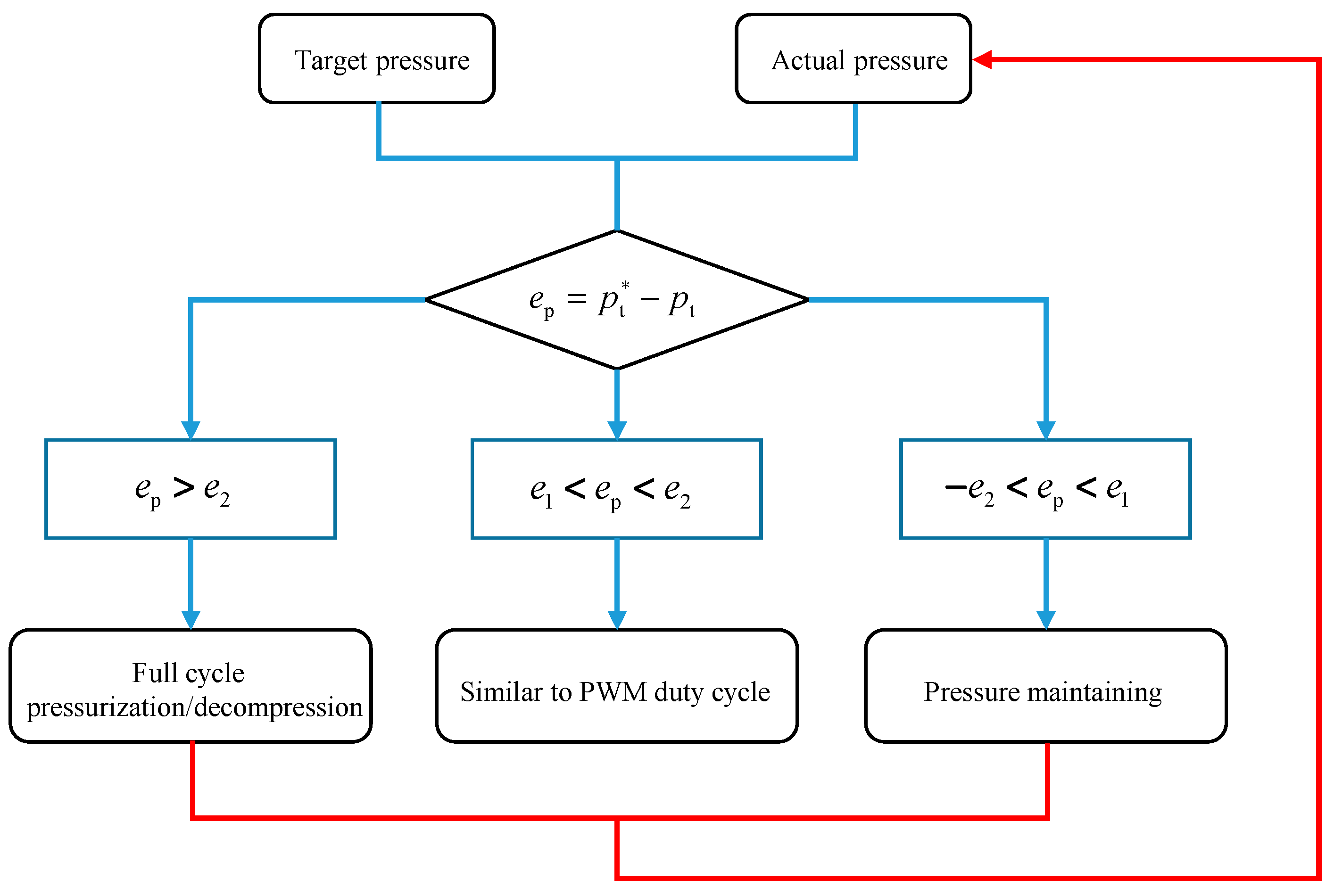
The manuscript designed a segmented controller according to the control error value, and the control logic is shown in Figure 8.
The control rate can be written in the form of a piecewise function, so the control rate u is expressed as (12), where u is the time (i.e., duty ratio) of pressurization or decompression in one control cycle. If u > 0, it is the pressure boosting process, and when u < 0, it is the pressure relieving process. Tc is the duration of the control cycle. α1, α2, β1 and β2 are the setting coefficients of the pressure control errors. Furthermore, e1 and e2 are the threshold values of the pressure control errors.
u = T c ,   e p > e 2 α 1 ( e p e 1 ) + β 1 ,   e 1 < e p < e 2 0 ,   e 1 < e p < e 1 α 2 ( e p + e 1 ) + β 2 ,   e 2 < e p < e 1 T c ,   e p < e 2

4.4. Determination of Air Pressure Control Parameters Based on SPWM

In order to determine the control parameters of the EPV module, the performance simulation experiment of the braking system in the process of slow pressurization and slow depressurization were carried out based on the SPWM pressure control method shown as Figure 9.
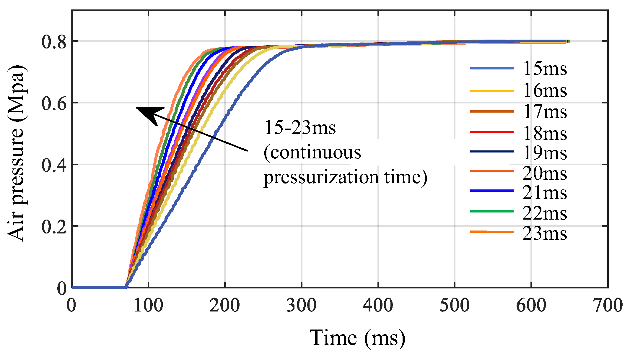
In the process of slow pressurization simulation, the pressure of the air source is maintained at 0.8 Mpa, the control cycle is 30 ms and the step length is 1ms. The pressurization time in each control period is changed from 0ms to 30 ms; that is, there are 31 combinations of {(0, 30), (1, 29), ……, (t1, t2), ……, (30, 0)}, where t1 is the pressurization time and t2 is the pressure maintaining time. From the simulation results, shown as Figure 10, it can be seen that when the pressurization time is 0, 1, 2, ……, or 13 ms, the booster valve is closed and the pressure is maintained at 0 Mpa. This phenomenon is caused by the establishment of the electromagnetic force of the solenoid valve and the hysteresis of the small valve controlling the large valve. When the pressurization time is 14 ms, the booster valve is at the opening/closing critical point. At this time, it is greatly affected by the external conditions. When the pressurization time is 15–23 ms, the pressurization rate of the solenoid valve is positively correlated with the pressurization duration. The longer the pressurization time, the faster the pressurization rate of the solenoid valve. Within this range, the pressurization rate could be adjusted by adjusting the pressurization duration. When the pressurization time is 24 ms, the booster valve is at the opening/closing critical point, and it is greatly affected by the external conditions too. When the pressurization time is more than 24 ms, the booster valve could not be closed and the pressurization rate was the maximum pressurization rate of the pneumatic valve, the pressurization rate was independent of the pressurization time. The results proved that, when the pressurization time was 15–23 ms (duty ratio 50–76.7%), the relationship between the pressurization rate and the pressurization duration of the solenoid valve under the SPWM control met the control requirements well.
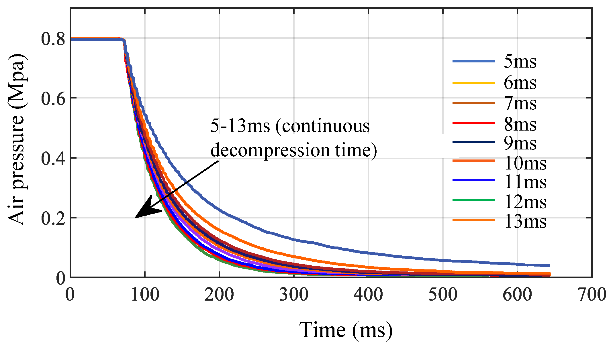
Similarly, in the process of slow depressurization simulation, shown as Figure 11, it is found that the relief valve is closed when the depressurization time is 0, 1, 2 or 3 ms, and the pressure is maintained at 0.8 Mpa without a pressure reduction. When the depressurization time is 4 ms, the relief valve is at the opening/closing critical point. At this time, it is greatly affected by the external conditions. When the depressurization time is 5–13 ms, the depressurization rate of the solenoid valve is positively correlated with the depressurization duration. The longer the depressurization time, the faster the depressurization rate of the solenoid valve. When the depressurization time is 14 ms, the relief valve is at the critical point, and it is greatly affected by the external conditions too. When the depressurization time is more than 14 ms, the relief valve could not be closed, and the depressurization rate is independent of the depressurization time. The results proved that, when the depressurization time is 5–13 ms (duty ratio 16.7–43.3%), the relationship between the depressurization rate and the depressurization duration under the SPWM control met the control requirements well.
When the EPV module changed from the pressure maintaining state to the pressurization state and from the depressurization state to the pressure maintaining state, the time delay of these two periods is about 12 ms. However, the time delay between the pressurization state to the pressure maintaining state and the pressure maintaining state to the depressurization state is about 4 ms. The reason is that the opening of the normally closed solenoid valve is driven by the electromagnetic force, and the closing is driven by the return spring. In conclusion, the pressurization or depressurization rates of the EPV module differed greatly with different duty cycles of the SPWM control. The control parameters of the EPV module based on SPWM are Tc = 30 ms, α1 = α2 = 100, β1 = 15, β2 = -5, e1 = 0.03 and e2 = 0.12. Then, the control rate Equation (12) can be written as (13).
u = 30 ,   e p > 0.12 100 ( e p 0.03 ) + 15 ,   0.03 < e p < 0.12 0 ,   0.03 < e p < 0.03 100 ( e p + 0.03 ) 5 ,   0.12 < e p < 0.03 30 ,   e p < 0.12
If |ep| > 0.12, the whole control cycle is used to increase (or decrease) the pressure; if 0.03 < |ep| < 0.12, the SPWM method is adopted and, if |ep| < 0.03, the process performed pressure maintaining control.

5. Dynamic Response Verification of Air Pressure Closed-Loop Control of EBS Bottom Controller Based on EPV Module

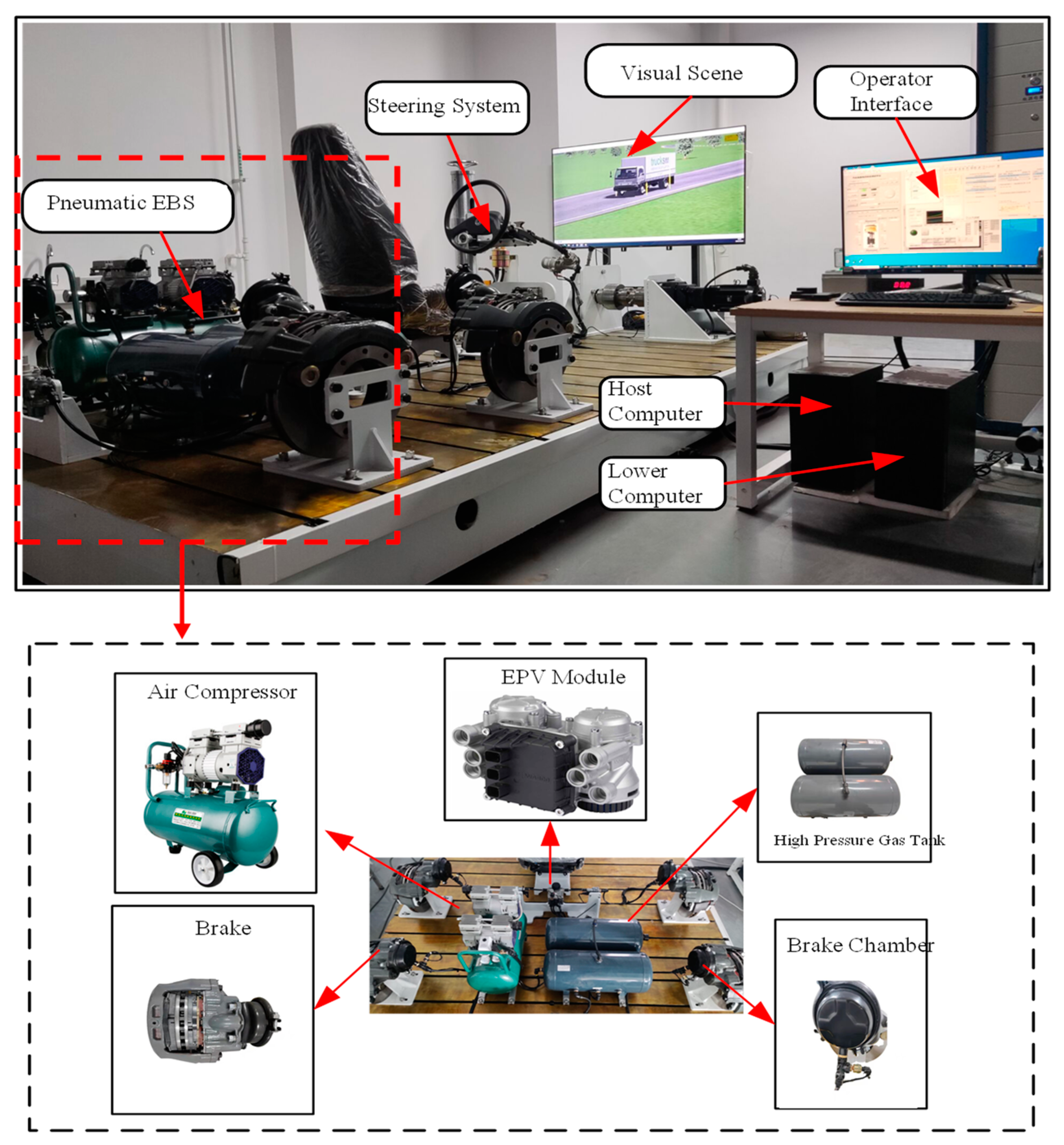
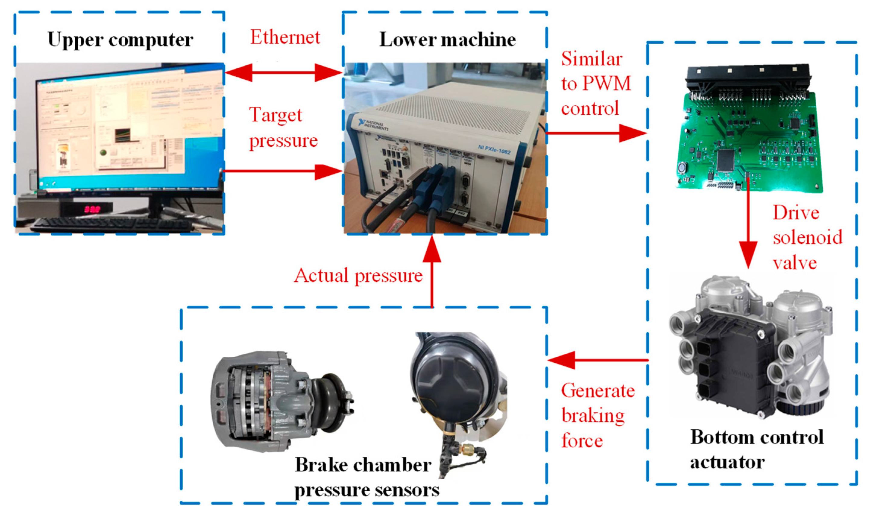
In order to verify the real-time effectiveness of the bottom controller, a commercial vehicle hardware in the loop test platform based on LabVIEW and the NI-PXI system is built, shown as Figure 12, and the dynamic response characteristics of EBS are tested under the SPWM control method.
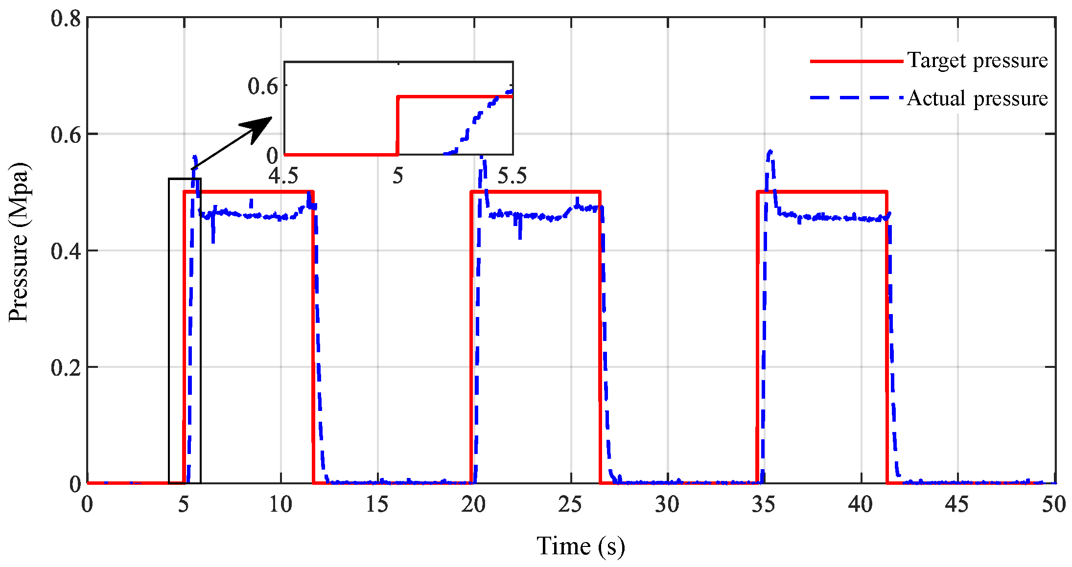
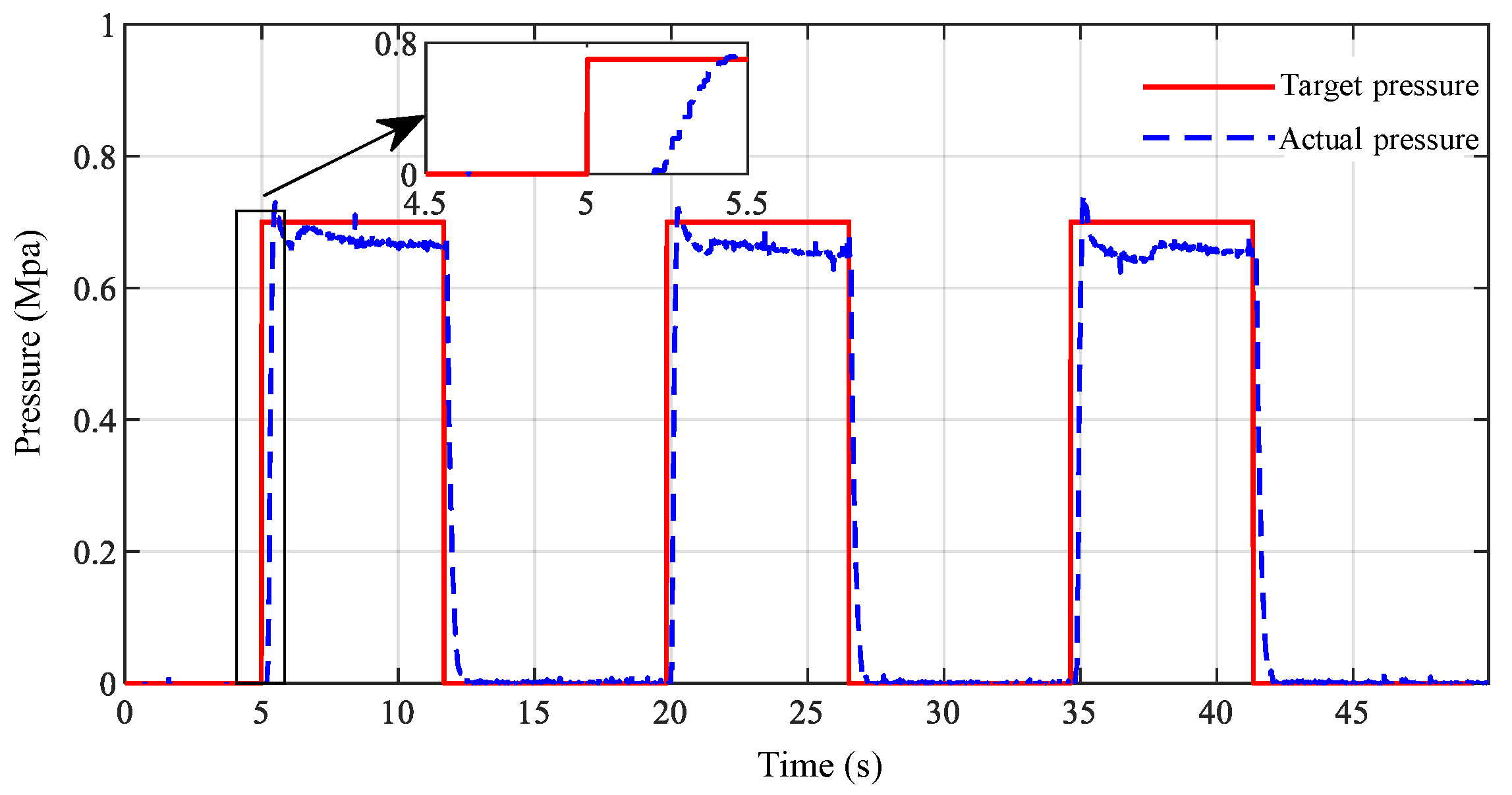
During the experiment, the air pressure control algorithm built based on LabVIEW is embedded in the lower computer. The lower computer sent the SPWM to the lower controller to drive the solenoid valve to realize the pressure control. At the same time, the actual air pressure signals collected by the pressure sensor of the brake air chamber are transmitted to the lower computer for closed-loop pressure control. As a man–machine interactive operation interface, the upper computer interacted with the lower computer PXI through the Ethernet. The pressure value of the high-pressure gas tank is set at 0.8Mpa, and the target pressure is set at 0.5 Mpa and 0.7 Mpa, respectively. Three groups of square wave signals are used for repeated pressurization, pressure-maintaining and pressure-reducing tests. The test results of the dynamic response characteristics and pressure following characteristics of EBS under the two target pressures are shown in Figure 13 and Figure 14.
According to the local enlarged diagram in Figure 13, during pressurization when the target air pressure is 0.5 Mpa, the EBS air pressure response time is about 0.2 s, the pressure build-up time (the time to reach the target value for the first time) is about 0.4 s, the steady-state error is always maintained at about 0.04 Mpa and the overshoot is about 0.06 Mpa. The main reason for overshoot is that the pressure difference between the high-pressure gas tank and the target pressure is large. In order to quickly reach the target pressure, a certain amount of overshoot would occur. In addition, the sudden change of the air pressure around the pressure sensors and the nonlinear response error of the solenoid valve would also lead to a certain amount of overshoot, but the overshoot time is very short and would not affect the braking effect during driving.
According to the local enlarged diagram in Figure 14, during pressurization when the target air pressure is 0.7 Mpa, the EBS air pressure response time is about 0.22 s, the pressure build-up time is about 0.45 s, the steady-state error is always maintained at about 0.03 Mpa and the overshoot is small; it is about 0.03 Mpa. It is thus clear that, when the target pressure is high, the steady-state error and the overshoot are smaller. Since the pressure difference between the target pressure and the high-pressure gas tank is small, the overshoot and the steady-state error are small, and the control accuracy is higher.
Using the commercial vehicle hardware in the loop test platform based on LabVIEW and the NI-PXI system, the continuous control of the discontinuous solenoid valve is realized by using the SPWM control method, which ensured that the air pressure closed-loop control of the EBS bottom controller had good dynamic response characteristics and could meet the requirements of providing the execution basis for the vehicle BBW system.

6. Conclusions

In this research, an integrated electromagnetic pneumatic valve (EPV) combination module is designed to solve the air pressure control problems of a slow response, large dynamic error and poor braking effect in the traditional EBS of the commercial vehicle braking process. By analyzing the dynamic characteristics of the EPV module, the key components dynamic models of the EPV module are established. Based on the dynamic models, the bottom controller and air pressure closed-loop control logic of EBS are designed. A novel SPWM air pressure control method is proposed to realize the precise regulation of the electromagnetic pneumatic valves control air pressure in the EPV module, so that it had good dynamic response characteristics. Finally, the hardware in the loop test platform of commercial vehicle EBS is built based on LabVIEW and the NI-PXI system. The experimental results showed that the response time of the air control method based on the EPV module is about 0.2 s, which is lower than the average value of the current methods (about 0.3 s), and the pressure build-up time is about 0.45 s, which is less than the value specified in the GB12676-2014 (The time from stable output of air pressure to 75% of the maximum test pressure does not exceed 0.6 s). Through the HIL test, the effectiveness of the EBS bottom controller under the control target pressure is verified, which provided the execution basis for the wire controlled pneumatic braking of commercial vehicle EBS.

Author Contributions

Conceptualization, L.Z. and J.W.; methodology, L.Z.; software, Q.Z. and Y.Y.; validation, Y.Y., L.Z. and J.W.; formal analysis, D.F.; investigation, G.Z.; resources, J.W.; data curation, L.Z.; writing—original draft preparation, L.Z.; writing—review and editing, L.Z., J.W. and Y.Y. All authors have read and agreed to the published version of the manuscript.

Funding

This research was funded by Liaocheng University, Grant number 318051824.

Data Availability Statement

No external data were used in this study.

Conflicts of Interest

The authors declare no conflict of interest.

References

  1. Miller, J.I. Advanced Braking Systems for Heavy Vehicles. Ph.D. Thesis, University of Cambridge, Cambridge, UK, 2010. [Google Scholar]
  2. Liu, Q.; Dong, Y.; Zhao, L.; Ma, C. Modeling, Control and Test of a Novel Electronic Pneumatic Brake System. IOP Conf. Ser. Mater. Sci. Eng. 2019, 631, 042030. [Google Scholar] [CrossRef]
  3. Zhang, D.; Zong, C.; Yang, S.; Zhao, W. Development and Verification of Electronic Braking System ECU Software for Commercial Vehicle; SAE Technical Paper 2013-01-2736; Society of Automotive Engineers (SAE): Warrendale, PA, USA, 2013. [Google Scholar] [CrossRef]
  4. Bao, H.; Wang, Z.; Liu, Z.; Li, G. Study on Pressure Change Rate of the Automatic Pressure Regulating Valve in the Electronic-Controlled Pneumatic Braking System of Commercial Vehicle. Processes 2021, 9, 938. [Google Scholar] [CrossRef]
  5. Zhang, D.; Zong, C.; Wan, Y.; Zheng, H.; Zhao, W.Q. Development and Research on Control Strategy of Advanced Electronic Braking Systems for Commercial Vehicle; SAE Technical Paper 2014-01-2285; Society of Automotive Engineers (SAE): Warrendale, PA, USA, 2014. [Google Scholar] [CrossRef]
  6. Miller, J.I.; Henderson, L.M.; Cebon, D. Designing and Testing an Advanced Pneumatic Braking System for Heavy Vehicles. Proc. Inst. Mech. Eng. Part C J. Mech. Eng. Sci. 2013, 227, 1715–1729. [Google Scholar] [CrossRef]
  7. Bao, H.; Wang, Z.; Wei, X.; Li, G. Study on the Structural Configurations and Pressure Regulation Characteristics of the Automatic Pressure Regulating Valve in the Electronically Controlled Pneumatic Brake System of Commercial Vehicles. Appl. Sci. 2021, 11, 10603. [Google Scholar] [CrossRef]
  8. Leontiev, D.; Klimenko, V.; Mykhalevych, M.; Don, Y.; Frolov, A. Simulation of Working Process of the Electronic Brake System of the Heavy Vehicle. In Mathematical Modeling and Simulation of Systems (MODS): Advances in Intelligent Systems and Computing; Springer: Cham, Switzerland, 2019; Volume 1019. [Google Scholar] [CrossRef]
  9. Day, A.J.; Ho, H.P.; Hussain, K.; Johnstone, A. Brake System Simulation to Predict Brake Pedal Feel in a Passenger Car; SAE Technical Papers 2014, Report No. 09BC-0077; SAE International: Warrendale, PA, USA, 2009. [Google Scholar]
  10. Ma, T.; Qian, C. The Modeling and Simulation of Pneumatic ABS Pressure Regulator Based on AMESim. Adv. Mater. Res. 2014, 971–973, 811–815. [Google Scholar] [CrossRef]
  11. David, R.; Neumann, R.; Murrenhoff, H. Simplified Fluid Transmission Line Model for Pneumatic Control Applications. In Proceedings of the 14th Scandinavian International Conference on Fluid Power (SICFP15), Tampere, Finland, 20–22 May 2015; Volume 6. [Google Scholar]
  12. Chen, L.; Wang, H.; Cao, D. High-precision Hydraulic Pressure Control Based on Linear Pressure-Drop Modulation in Valve Critical Equilibrium State. IEEE Trans. Ind. Electron. 2017, 64, 7984–7993. [Google Scholar]
  13. Farid, B.; Helmus, T.; Lumkes, J. The Impact of Peak-and-Hold and Reverse Current Solenoid Driving Strategies on the Dynamic Performance of Commercial Cartridge Valves in a Digital Pump/Motor. Int. J. Fluid Power 2016, 17, 37–47. [Google Scholar]
  14. Edmond, R.; Hurmuzlu, Y. A high performance pneumatic force actuator system: Part I—Nonlinear mathematical model. ASME J. Dyn. Syst. Meas. Control 2000, 122, 416–425. [Google Scholar]
  15. Chol, H.J.; Zhao, W.Q.; Zong, C.F.; Zheng, H.Y. Simulation and HIL Test for Proportional Relay Valve of Commercial Vehicle Pneumatic EBS. Appl. Mech. Mater. 2013, 437, 418–422. [Google Scholar] [CrossRef]
  16. Seung, C.J.; Kim, J.; Jeon, J. New brake by wire concept with mechanical backup. SAE Int. J. Passeng. Cars-Mech. Syst. 2012, 5, 1194–1198. [Google Scholar]
  17. Barlsen, H.; Stender, A.; Tha, I.; Witte, N.; Wolf, M. Electronic Braking System and Method for Drawbar Trailers. U.S. Patent 8,267,485, 18 September 2012. [Google Scholar]
  18. Lei, M. Simulation Research and Detection System Development of ABS Relay Valve. Master’s Thesis, China Institute of Metrology, Hangzhou, China, 2012. [Google Scholar]
  19. Li, Y. Hardware in the Loop Simulation of Pneumatic ABS for Commercial Vehicles. Master’s Thesis, Yanshan University, Qinhuangdao, China, 2018. [Google Scholar]
  20. Shi, Y.; Lu, Y.; Wang, X.; Luo, Z. Analysis of the brake Valve Dynamic Characteristics Based on AMEsim. Instrum. Tech. Sens. 2014, 23–26. [Google Scholar] [CrossRef]
  21. An, Z. Design of Relay Valve Detection System. Master’s Thesis, China Institute of Metrology, Hangzhou, China, 2013. [Google Scholar]
  22. Wan, Y.; Zhang, D.; Weiqiang, Z.; Zong, C.; Han, J. Development of Simulation Platform and Compensation Control Strategy for Pneumatic Electric Control Braking System. J. Jilin Univ. Eng. Ed. 2016, 46, 711–717. [Google Scholar]
  23. Wang, S.; Zhang, B.; Zhong, Q.; Yang, H. Study on Control Performance of Pilot High-Speed Switching Valve. Adv. Mech. Eng. 2017, 9, 1687814017708908. [Google Scholar] [CrossRef] [Green Version]
  24. Liu, X.; Chen, H.; Yuan, J. Research on Control Method of Proportional Relay Valve for EBS of Commercial Vehicle. In Proceedings of the Annual Meeting of China Society of Automotive Engineering, Changchun, China, 15–18 July 2010. [Google Scholar]
  25. You, M.; Zhang, J.; Sun, D.; Gou, J. Characteristics Analysis and Control Study of a Pneumatic Proportional Valve. In Proceedings of the 2015 IEEE Advanced Information Technology, Electronic and Automation Control Conference (IAEAC 2015), Chongqing, China, 19–20 December 2015; pp. 242–247. [Google Scholar] [CrossRef]
  26. Zheng, H.; Ma, S.; Liu, Y. Vehicle Braking Force Distribution with Electronic Pneumatic Braking and Hierarchical Structure for Commercial Vehicle. Proc. Inst. Mech. Eng. Part I J. Syst. Control Eng. 2018, 232, 481–493. [Google Scholar] [CrossRef]
  27. Wan, Y.; Zhang, D.; Weiqiang, Z.; Zong, C.; Han, J. Development of Simulation Platform and Control Strategy of Electronic Braking System for Commercial Vehicles; SAE Technical Paper, 2014-01-2286; Society of Automotive Engineers (SAE): Warrendale, PA, USA, 2014. [Google Scholar] [CrossRef]
  28. Kong, X.; Zhang, J.; Li, T.; Chang, L. Research on Liner Pressure Control of Force Control System of High-speed Switch Solenoid Valve. J. Mech. Eng. 2014, 50, 192–199. [Google Scholar] [CrossRef]
  29. Bali, E.; Erzan Topcu, E. Design of On-Off Type Solenoid Valve for Electro-Pneumatic Brake Systems and Investigation of Its Static Characteristics. Int. J. Adv. Automot. Technol. 2018, 2, 175–184. [Google Scholar]
  30. Wu, J.; Zhang, J.; Nie, B.; Liu, Y.; He, X. Adaptive Control of PMSM Servo System for Steering-by-Wire System with Disturbances Observation. IEEE Trans. Transp. Electrif. 2021, 8, 2015–2028. [Google Scholar] [CrossRef]
  31. Wu, J.; Kong, Q.; Yang, K.; Liu, Y.; Cao, D.; Li, Z. Research on the Steering Torque Control for Intelligent Vehicles Co-Driving With the Penalty Factor of Human-Machine Intervention. IEEE Trans. Syst. Man Cybern. Syst. 2022, 1–12. [Google Scholar] [CrossRef]
  32. Yan, Y.; Wu, J.; Liu, X.; Zhao, Y.; Wang, S. A lateral trajectory tracking control method for intelligent commercial vehicles considering active anti-roll decision based on Stackelberg equilibrium. IET Intell. Transp. Syst. 2022, 16, 1193–1208. [Google Scholar] [CrossRef]
  33. Wu, J.; Tian, Y.; Walker, P.; Li, Y. Attenuation reference model based adaptive speed control tactic for automatic steering system. Mech. Syst. Signal Process. 2021, 156, 107631. [Google Scholar] [CrossRef]
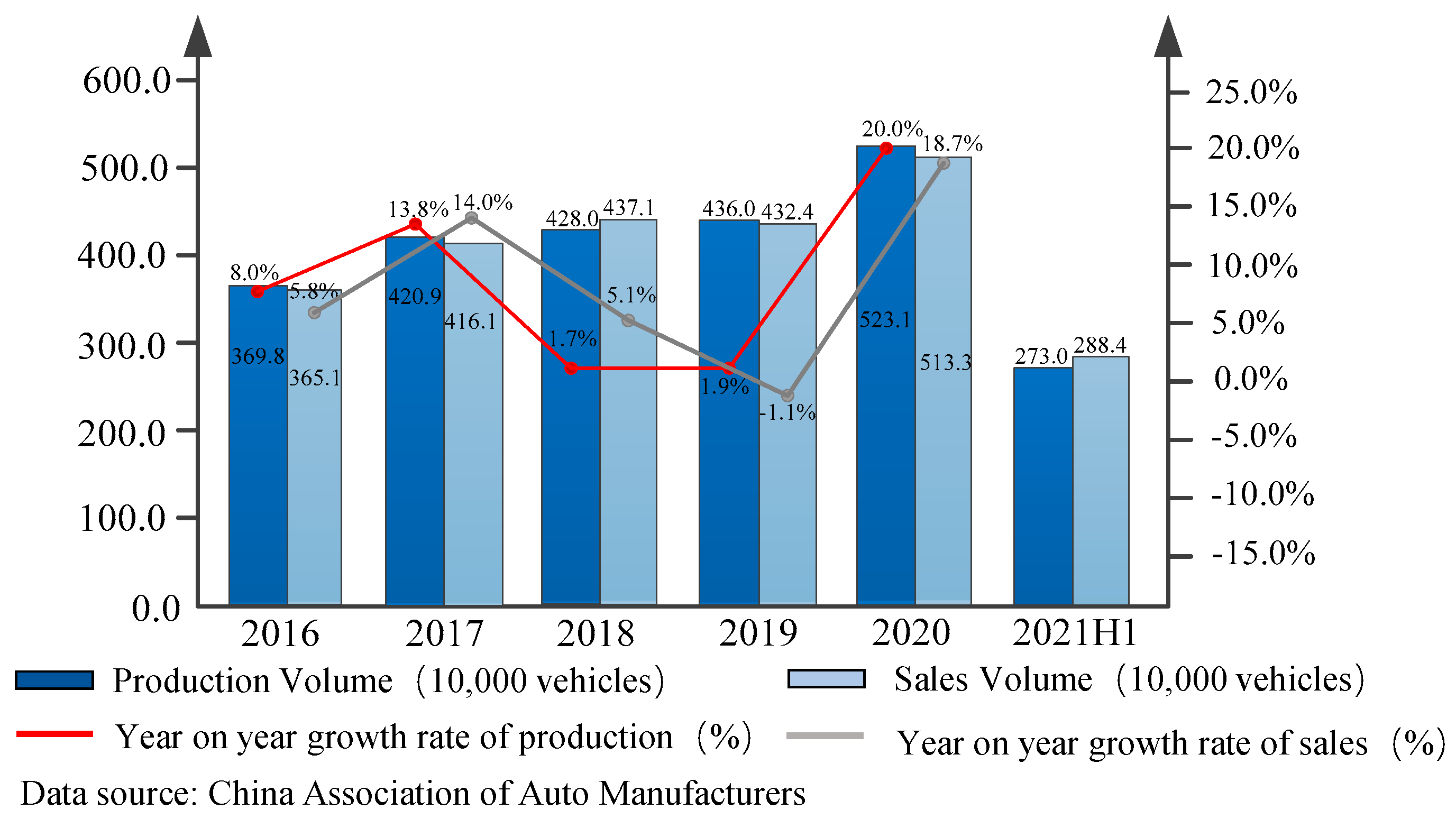
Figure 1. 2016–2021 (H1) development trend of China’s commercial vehicle market.
Actuators 11 00316 g001
Figure 2. EBS structural layout and schematic diagram based on the EPV module.
Actuators 11 00316 g002
Figure 3. Schematic diagram of BBW pneumatic valves based on EPV.
Actuators 11 00316 g003
Figure 4. Schematic diagram of the EPV module dynamic characteristic analysis.
Actuators 11 00316 g004
Figure 5. Hardware logic block diagram of the EBS bottom controller based on the EPV module.
Actuators 11 00316 g005
Figure 6. Schematic diagram of EBS pressurization, pressure maintaining and depressurization cycle.
Actuators 11 00316 g006
Figure 7. Schematic diagram of the SPWM control method.
Actuators 11 00316 g007
Figure 8. Logic block diagram of the segmented air pressure controller.
Actuators 11 00316 g008
Figure 9. The performance simulation experiment platform of the braking system.
Actuators 11 00316 g009
Figure 10. Relationship curve between the pressurization rate and pressurization duration.
Actuators 11 00316 g010
Figure 11. Relationship curve between the depressurization rate and depressurization duration.
Actuators 11 00316 g011
Figure 12. Logic block diagram of air pressure control HIL of the EBS bottom controller.
Actuators 11 00316 g012
Figure 13. Air pressure response curve of 0.5 MPa target pressure during braking.
Actuators 11 00316 g013
Figure 14. Air pressure response curve of 0.7 MPa target pressure during braking.
Actuators 11 00316 g014
Table 1. External interface and relevant parameters of the bottom controller.
Signal NamesParametersNumbers
Displacement sensor of the brake pedalvoltage nominal value: 24 V
current top limit: 1 A
1 channel
Ignition switchvoltage nominal value: 24 V
current top limit: 1 A
1 channel
Booster/Relief valvevoltage nominal value: 24 V
current top limit: 2 A
4 channels
Standby pressure valvevoltage nominal value: 24 V
current top limit: 2 A
2 channels
24 V Power supplyRated output voltage: 24 V
capacity:105 Ah
1 channel
CAN signalsBaud rate: 250 K2 channels
Pressure sensor of the brake air chamberOutput voltage: 0.5–4.5 V4 channels
Table 2. Air pressure control logic of single wheel braking.
ProcessBooster Valve StateRelief Valve State
Pressure boosting Power offOpenPower offClose
Pressure maintainingPower onClosePower offClose
Pressure relievingPower onClosePower onOpen
Publisher’s Note: MDPI stays neutral with regard to jurisdictional claims in published maps and institutional affiliations.