Abstract
In this paper, a claw-pole magnetic levitation torque motor (CPMLTM) utilizing cogging torque is proposed as an electromechanical converter (EMC) for two-dimensional valves (2D valve). Compared to the existing torque motor, CPMLTM utilizes the cogging torque between the stator and the rotor, and has the ability of automatic neutral adjustment, which greatly reduces the difficulty of neutral adjustment of two-dimensional valves and improves the accuracy of neutral adjustment. First, the structure and working principle of CPMLTM are introduced, followed by an analysis of the cogging torque of CPMLTM based on the energy method and Fourier expansion. The effects of the claw pole tooth (CPT) shape and slot opening coefficient on the cogging torque of CPMLTM are investigated. To analyze the sensitivity of the electromagnetic torque to each design parameter, a qualitative expression for the electromagnetic torque containing various design parameters was derived based on the equivalent magnetic circuit method, and a set of orthogonal tests were designed to calculate the electromagnetic torque using the finite element method (FEM). To demonstrate the feasibility of the proposed CPMLTM principle and to verify the correctness of the cogging torque analysis model and FEM, a prototype was fabricated and a test rig was constructed for experimental study. The experiments show that CPMLTM can indeed utilize cogging torque to achieve automatic neutral adjustment, and that the neutral adjustment is more accurate. Moreover, the CPMLTM has good static and dynamic characteristics: a neutral electromagnetic torque of 0.1 Nm at a coil magnetomotive force (MMF) of 100 A, step response time up to 4.575 ms, and amplitude frequency bandwidth and phase frequency bandwidth of 173.7 Hz and 86.5 Hz, respectively.
1. Introduction
Electro-hydraulic systems have been widely used in aerospace, robotics, and construction machinery due to the successful integration of the fast dynamic response, easy signal transmission and processing of electronics with a high work-to-weight ratio, and the infinitely adjustable speed of hydraulic systems [1,2,3,4,5,6]. As the key control element of an electro-hydraulic system, servo valves run through the control of the spool displacement to adjust the gap between the spool and the valve sleeve to achieve the control of flow and pressure [7,8]. Servo valves can generally be divided into direct-acting valves and pilot valves. Direct-acting valves are directly pushed by EMCs. Limited by the thrust of the EMC, direct-acting valves are generally used in low-pressure, low-flow applications. In order to overcome the influence of Bernoulli force and friction, as well as to realize the application in high pressure and high flow rates, it is necessary to convert and amplify the mechanical force of EMC into hydraulic pressure that can easily drive the valve spool through the pilot stage [9]. The nozzle flapper valve and jet pipe valve are the two most common pilot stage servo valves [10,11]. Nozzle flapper valves and jet pipe valves control fast dynamic response and high accuracy and are widely used for various flight attitude control of aircrafts. The gap between the nozzle and the flapper of the nozzle flapper valve is approximately 0.025–0.1 mm, which is less resistant to contamination. The jet pipe valve is more resistant to contamination, but jet characteristics are not easy to predict [12,13].
A 2D valve based on a hydraulic servo-spiral mechanism was proposed by [14]. The 2D valve concentrates the pilot and power stages structurally in the spool and drives the spool rotation through an EMC, and the rotation process changes the unique sensitive cavity of the 2D valve, thus generating hydraulic pressure to push the spool straight and achieve controlled flow and pressure [15,16]. By introducing the servo screw structure, the 2D valve greatly simplifies the structure of the servo valve and further improves the work-to-weight ratio.
As a bridge between the hydraulic part and the electrical part of 2D valve, the EMC is a crucial core driving element. The key of the EMC is the magnetic circuit in it, so the magnetic circuit modeling of the EMC has been a hot topic of interest among scholars. In [17], a novel high-torque density hybrid pole array torque motor was proposed, and a fully parametric high-precision equivalent magnetic circuit model was established by considering the reluctance of the magnetic conductive material and the leakage of the excitation coil and permanent magnet (PM) material. In [18], a high-precision equivalent magnetic circuit model of a non-uniformly slotted permanent magnet finite rotation angle torque motor was proposed. In order to establish an equivalent magnetic circuit model that can fully consider the magnetic saturation problem and armature response, the reluctance of the stator tooth tip section, PM poles and air gap region are divided relatively finely. In [19], a generalized equivalent magnetic circuit model was proposed in the preliminary design of a toroidal winding finite-torque motor. This model takes into account the nonlinear saturation effect of the permeable material and represents the magnetic circuit as a function of the number of magnetic poles and geometry. In [20], it was considered that the working air gap magnetic leakage is not constant, and a mathematical model of a torque motor with two working air gaps was developed in order to consider the air gap leakage flux that varies with the armature rotation angle. The FEM is also used to explain the existence of a linear relationship between the working air gap magnetic leakage and the armature rotation angle in a certain range of rotation angles.
In EMCs, cogging torque has long been a hot topic of interest for scholars because cogging torque can negatively affect machine performance [21,22,23]. The cogging torque is generated because of the physical structure of the machine itself, and cogging torque causes pulsations in the output torque and brings vibration and noise. Scholars generally start from the structure of the machine itself and change the machine structure and structural parameters during the design process to weaken the cogging torque. In [24], a closed-form analysis technique was proposed to analyze a table-mounted PM motor with fractional-slot concentrated windings, through which it was found that a suitable pole-slot fit can effectively weaken the cogging torque. Changing the pole arc coefficient of the motor can significantly affect the phase and amplitude of the cogging torque waveform. Analysis in [25] showed the effect of different pole arc coefficients on the cogging torque waveform by means of Fourier series expansion. Appropriate dummy slots on the stator without inlaid windings can be useful for weakening the cogging torque. In [26], the effect on the cogging torque when an auxiliary slot is added to the stator teeth is studied, and a calculation method to calculate the width of the auxiliary slot is given. A suitable tooth width can contribute to weakening the cogging torque. In [27], the effect of different stator tooth sizes on cogging torque, torque pulsation, and cogging harmonics in a PM synchronous motor were investigated. Rotor eccentricity can lead to a significant increase in tooth slot torque. A novel analytical model combining the equivalent magnetic circuit method and subdomain valves was proposed in [28] to predict the cogging torque of an eccentric surface-mounted PM motor with any combination of pole slots. In [29], the effect of rotor eccentricity on the cogging torque of a PM motor with different pole-slot number combinations was investigated using the analytical model and FEM. It was found that the effect of eccentricity decreases significantly with the increase of the maximum convention of the number of poles and the number of slots. In [30], the effects of dynamic and static rotor eccentricity on the electromagnetic performance of the PM motor, including the tooth slot torque and electromagnetic torque, were investigated.
Since the spool of a 2D valve moves directly while rotating, the EMC fixed to the 2D valve must have axial and circumferential degrees of freedom accordingly. The EMC for the 2D valve mentioned in [31] combines a stepper motor with a fork mechanism to accommodate both axial and circumferential motions in order to adapt to the dual-degree-of-freedom motion characteristics of the spool. In [32,33], a new EMC is formed by combining a proportional solenoid and a non-contact magnetic levitation coupling to achieve torque transfer, linear and rotary motion conversion, and spool position feedback. In order to reduce the manufacturing cost of the spool by replacing the complex spiral groove with a simple rectangular groove, a new EMC was proposed in [34]. This EMC is based on an annular air gap instead of the negative feedback function of the spiral groove, thus reducing the machining difficulty. In [35], a magnetic circuit model of an EMC was developed, which considered the eddy current effect and calculated the eddy current resistance value by considering the skin effect. The structure principle of the EMC in this literature is similar to that of the EMCs in the touch-nozzle baffle valve and the jet pipe valve, where the PMs generate polarized flux, and the control flux generated by the coil interacts in the four air gaps to generate the differential torque that drives the armature rotation.
The 2D valve uses a servo spiral mechanism to convert the angular displacement of the spool into proportional axial movement of the spool. When the spool is in the circumferential neutral position, the spiral-sensitive groove in the servo spiral mechanism overlaps the high-pressure hole and low-pressure hole equally, and the spool is in the axial neutral position under the control of the servo spiral mechanism. When the spool deviates from the circumferential neutral position, the overlapping area of the spiral-sensitive groove and the high-pressure and low-pressure holes are not equal, the axial force of the spool is not balanced, and the spool cannot be kept in the axial neutral position. Therefore, it is necessary to ensure that the spool is in a circumferential neutral position in order to ensure that the spool is in neutral position when it is not in operation. Since the spool is firmly connected to the EMC rotor, it is critical that the EMC be adjusted in a neutral manner and with accuracy. Since the angular displacement and axial movement of the spool are proportional to each other, an EMC with a larger angular displacement can increase the spool stroke and increase the output flow rate, which is of great importance to the performance of 2D valves. In order to simplify the neutral adjustment method of EMC as well as improve its accuracy and increase the output angular displacement, this paper proposes a CPMLTM using the cogging torque.
This paper is organized as follows. In Section 2, the structural principle of the CPMLTM is introduced. In Section 3, the mathematical model of cogging torque of CPMLTM is established by Fourier analysis through the energy method. The effects of CPT shape and the slot opening coefficient on the cogging torque are investigated respectively. In Section 4, the qualitative equation of electromagnetic torque of CPMLTM is derived first by using the equivalent magnetic circuit method under the neglect of magnetic resistance of magnetically conductive materials and various magnetic leakage. Then, the sensitivity of the electromagnetic torque of CPMLTM to each design parameter is analyzed based on orthogonal tests and through FEM. In Section 5, a prototype of CPMLTM is fabricated and assembled, and a special test rig is built to measure the torque-angle characteristics, step response, and torque-current relationship curves of the cogging torque and electromagnetic torque.
2. Structure and Operating Principle
CPMLTM is the EMC applied to the 2D valve, so this paper first introduces the working principle of the 2D valve, whose spool has two degrees of freedom: circumferential rotation and axial reciprocation. These two degrees of freedom are non-interfering with each other. The working principle of the 2D valve is shown in Figure 1. In the figure, P is the oil inlet, T is the oil tank, A and B are the working oil ports, ω is the angular displacement. The spool shoulder has two holes of equal size: a high-pressure hole and a low-pressure hole. There is a spiral-sensitive groove on the valve sleeve; when the spool is in axial and circumferential neutral position, the spiral-sensitive groove overlaps with the high-pressure and low-pressure holes with equal area. There is a high-pressure chamber and a sensitive chamber between the spool and the sleeve. The high-pressure chamber is connected to the oil inlet and always maintains a constant high pressure; the sensitive chamber communicates with the high-pressure and low-pressure holes on the spool shoulder through the spiral-sensitive groove, and the pressure in the sensitive chamber is controlled by the hydraulic resistance half bridge composed of the spiral-sensitive groove, high-pressure hole, and low-pressure hole. Initially, the pressure in the sensitive chamber is equal to half of the pressure in the high-pressure chamber, the spool area at one end of the high-pressure chamber is twice the spool area at one end of the sensitive chamber, and the spool is axially balanced. When the torque motor inputs a counterclockwise angular displacement, the spool rotates and the overlapping area between the high-pressure chamber and the spiral-sensitive chamber increases. The pressure in the sensitive chamber increases, the axial force balance of the spool is broken, and the spool moves straight to the left axially. In the process of direct motion, the overlapping area of the spiral-sensitive groove and the high-pressure chamber gradually decreases, and the overlapping area with the low-pressure chamber gradually increases. Finally, the overlapping area of the spiral-sensitive groove and the high-pressure hole and low-pressure hole are equal again, and the spool reaches a new equilibrium position. Through the working principle of the 2D valve, we can find that the circumferential neutral position of the spool is very significant, and when the spool is in the circumferential neutral position with the torque motor rotor, the spool will be axially balanced.
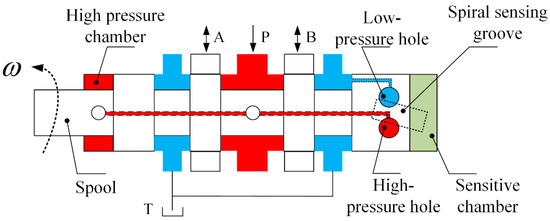
Figure 1.
Working principle diagram of 2D valve.
The CPMLTM has degrees of freedom in both axial and circumferential directions, and its structure is shown in Figure 2. The rotor shaft, PM, and shell are the components of the rotor assembly; the claw pole, the magnetic conductive sleeve, the coil, and its bone are the components of the stator assembly. The claw pole includes the upper claw pole with the same structure and the lower claw pole with the teeth facing downward, and the distance between each CPT is equal when the upper and lower claw poles fit together. The cavity formed between the upper claw pole and the lower claw pole is equipped with a coil skeleton wound with coils, and the coil skeleton and the claw pole are fit together by interference. The inner wall of the ring shell is uniformly provided with a plurality of PMs along the circumference, and the magnetic poles of two adjacent PMs are opposite in the radial direction. The PM of CPMLTM is 1 mm longer than the stator claw pole in the axial direction, and the PM always covers the claw pole during the axial movement of the rotor. Therefore, theoretically, the output electromagnetic torque of CPMLTM does not change when the axial relative position of stator and rotor changes. The air gap between the CPT and the PMs is the working air gap, and the radial spacing of the working air gap is always constant.
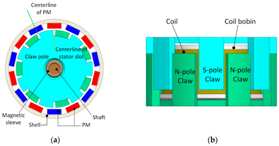
Figure 2.
The structure diagram of CPMLTM. (a) Stator-rotor relative position diagram, (b) Stator structure diagram.
When the coil between the upper and lower claw poles is energized, axial magnetic flux will be generated in the upper and lower claw poles. The upper and lower CPT will be magnetized by the axial magnetic flux into S-pole teeth and N-pole teeth, respectively, as shown in Figure 2b. The axial flux will be converted into radial flux in the CPT, and the converted radial flux will interact with the polarized flux generated by the PM in the working air gap, which results in an increased flux density in one part of the air gap and a decreased flux density in the other part of the air gap, which will cause the rotor to produce angular displacement under the differential action.
In order to explain the working principle of CPMLTM more concisely, the magnetic circuit between the stator and rotor can be simplified to the planar magnetic circuit diagram shown in Figure 3. where N, S represent the magnetic poles of PM respectively. When the coil winding is not energized, only the polarization flux generated by the PM exists in the torque motor, and the polarization flux is shown by the red solid line; when the coil winding is energized, a control flux is generated in the torque motor, and the control flux is shown by the blue dashed line. The control flux and the polarized flux cancel each other in air gap ① and ③, and the flux density in them decreases; in air gap ② and ④, they superimpose each other, and the flux density in them increases. Under the differential action, the rotor produces a counterclockwise angular displacement .
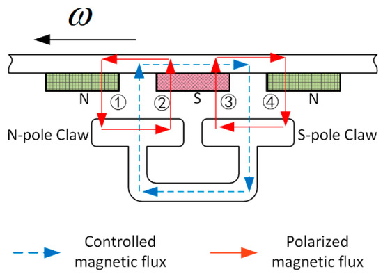
Figure 3.
The planar magnetic circuit of CPMLTM.
As an EMC for hydraulic valves, the accuracy and ease of their neutralization (alignment performance) is important to the performance of hydraulic valves and even hydraulic systems. The structure of a conventional moving-iron torque motor is shown in Figure 4. The kinematic torque motor consists of a zero-adjustment screw, zero-adjustment spring, armature, limit block, PM, magnetic conductor, and coil. Like the CPMLTM, the moving-iron torque motor generates electromagnetic torque by driving the armature through the differential action of the polarization flux and the control flux. In terms of neutral adjustment, the moving-iron torque motor can be adjusted with the aid of four zero-adjustment screws and four zero-adjustment springs. When the coil is not energized, the armature is balanced only when it is in the absolute neutral position so that the magnetic circuits of the PMs cancel each other out. Once the armature deviates slightly from the neutral position, the magnetic force on the armature will be out of balance, thus quickly moving away from the neutral position. Therefore, the neutral position of the moving-iron torque motor is an unstable positioning point that cannot be maintained in practice and needs to be assisted by the zero-adjustment screw and zero-adjustment spring. The zero-adjustment screw and zero-adjustment spring are used to determine the center position manually, which has poor accuracy and difficult adjustment. The relationship between the angular displacement and the applied torque of the moving-iron torque motor with and without a spring is shown in Figure 5.
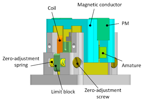
Figure 4.
The structure diagram of moving iron torque motor.
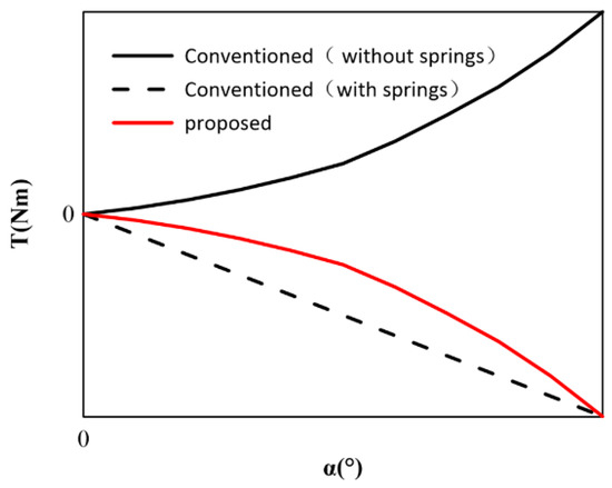
Figure 5.
Angular displacement-torque diagram.
However, the rotor of CPMLTM is automatically suspended in the axial and circumferential neutral positions by magnetic force. In CPMLTM, the height of the PM is greater than the stator, and the stator is automatically suspended in the axial neutral position by the magnetic force of the PM. If the rotor produces an axial displacement away from the axial neutral position, it is subjected to an axial restoration force in the opposite direction of the axial displacement, which brings it back to the axial neutral position. When the coil winding is not energized, the rotor is automatically suspended in the circumferential neutral position under the action of the cogging torque when the centerline of the stator slot overlaps with the centerline of the rotor PM, as shown in Figure 2a. If the rotor produces an angular displacement away from the circumferential neutral position, it will be subjected to a cogging torque in the opposite direction of the angular displacement, which will bring it back to the circumferential neutral position. The relationship between the angular displacement and the torque applied to the CPMLTM is shown in Figure 5.
In this study, the counterclockwise direction is defined as the positive direction. A comparison of the CPMLTM and the moving-iron torque motor in Figure 5 shows that the CPMLTM has the same centering and de-energized reset functions as the moving-iron torque motor without the need for additional zero-adjustment screws and zero-adjustment springs. Since the CPMLTM uses magnetic force for centering, its neutral adjustment is more convenient and accurate. Comparing the structure of the two torque motors, we can see that the CPMLTM has a simpler structure and can bring out the advantages of the high power–density ratio of hydraulic components to achieve the ultimate power–density ratio.
The CPMLTM designed in this study is an EMC applied to a 2D valve, whose structure is off the claw pole motor and completely different from the existing moving iron type torque motor. The three are compared in Table 1 to verify the novelty of CPMLTM.

Table 1.
Function comparison table.
3. Cogging Torque Analysis
3.1. Expression of Cogging Torque
The cogging torque is caused by fluctuations in the tangential component of the force interacting between the PM and the claw pole tooth slot, which always tries to keep the centerline of the PM aligned with the centerline of the CPT or claw pole slot. Figure 6 shows the cogging torque waveform during one cogging torque cycle. This cogging torque waveform plot reveals the existence of three evaluation indicators: peak value, peak-value angle position, and phase. The peak value is the maximum value of the absolute value of the cogging torque that appears in the cogging torque waveform. As the name implies, the peak-value angle position represents the rotor position at the peak of the cogging torque. When the value of the cogging torque is positive in a half cycle, the phase is positive, and vice versa for negative phase.
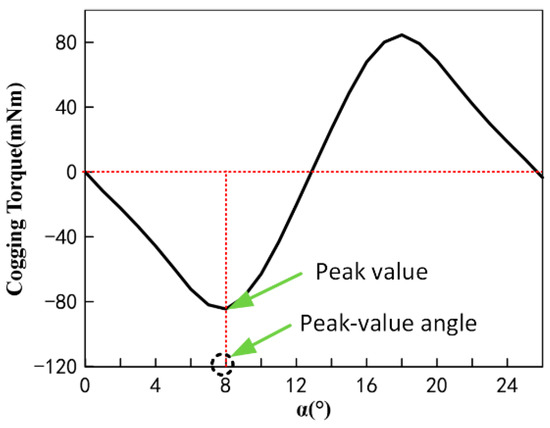
Figure 6.
Typical cogging torque waveform.
The geometry of the CPMLTM discussed in this paper is shown in Figure 2a. This study is predicated on the following assumptions:
(1) The magnetic permeability of the claw-pole teeth is infinite;
(2) The distribution of the magnetic field in the air gap is one-dimensional;
(3) The PM has the same permeability as air.
The cogging torque between the PM and the claw pole tooth slot can be calculated by the energy method. When the stator and rotor are moving relative to each other, the permeability between the CPT and the PM is almost constant, so the magnetic field around the CPT is also almost constant; however, the permeability between the CPT and the PM corresponding to the two sides of the PM varies greatly, which will cause the change of magnetic field energy storage and thus the cogging torque. Therefore, the slot torque can be expressed as
In this study, it is assumed that is the angle between the centerline of the PM and the centerline of the claw-pole slot, and W is the magnetic co-energy. If saturation is not considered and the permeability of the CPT is assumed to be infinite, the sum of the magnetic field energy in the working air gap and the PM is approximately equal to the energy stored in the magnetic field of the entire torque motor. Therefore, the energy stored in the magnetic field of the torque motor can be expressed as
where is the air permeability and the magnetic field energy depends on the structural size of the motor, the performance of the PMs, and the relative position between the stator and rotor.
In this study, the relative positions between the PM and the CPT are shown in Figure 7, which uses to indicate location of the centerline of the PM and to indicate the location of the centerline of the claw pole slot. The distribution of the air gap magnetic density along the surface of the CPT can be approximated as
where is the distribution of the residual flux density of the PM along the perimeter of the air gap, is the thickness of the PM along the magnetization direction, and is the distribution function of the effective air gap length. Therefore, Equation (2) can be expressed as
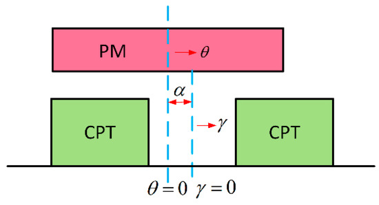
Figure 7.
Relative position of PM and CPT.
The magnetic co-energy can be calculated by expanding and into a Fourier series. The distribution of is shown in Figure 8. The Fourier expression is
where 2p is the number of pole pairs, is the residual flux density of the PM, is the pole arc coefficient, , .
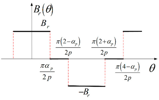
Figure 8.
Distribution of .
It is assumed that the flux generated by the PM passes through the air gap in the radial direction and then enters the claw pole slot along the circular trajectory, as shown in Figure 9. The effective air gap length within half the claw pole slot distance can be thus expressed as
where is the opening of the claw pole slot in meters, is the slot pitch in radians, is the slot opening in radians, is the slot opening coefficient equal to the ratio of slot opening to slot pitch (), and is the angle between the side of the CPT and the bottom of the slot.
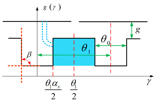
Figure 9.
Distribution of .
Simplify so that it can be expanded into a Fourier series [36].
If , then the approximation error is less than 5%. Thus the Fourier series expansion of can be expressed as
where and are shown in Equations (A1) and (A2) in Appendix B.
Equation (4) can be expanded as
where is the axial length of the CPT, is the outer diameter of the claw pole, and is the inner diameter of the shell.
The CPMLTM designed in this paper is an equipolar slot structure, i.e., . By bringing Equations (5), (8) and (9) into Equation (1), the expression of slot torque is obtained as
3.2. Influencing Factors of Cogging Torque Waveform
According to the expression of cogging torque, it can be seen that, for CPTs with the same pole arc coefficient and cogging opening coefficient, the difference of their shapes also has an effect on the basic index of cogging torque. Figure 10 gives the CPT shape diagrams of CPT and PM after planar expansion. The , , and in Figure 10a–c are acute, right angle, and obtuse angle, respectively.

Figure 10.
Shape of CPT.
In order to clarify the effect of on the cogging torque waveform of CPMLTM, the change of cogging torque waveform during the process of from acute angle to obtuse angle was calculated using FEM. The relationship curve between and the cogging torque peak is shown in Figure 11. The cogging torque waveform of CPMLTM when is acute, right angle, and obtuse angle are shown in Figure 12.
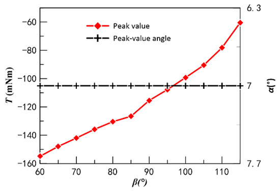
Figure 11.
Curve of β versus peak cogging torque.
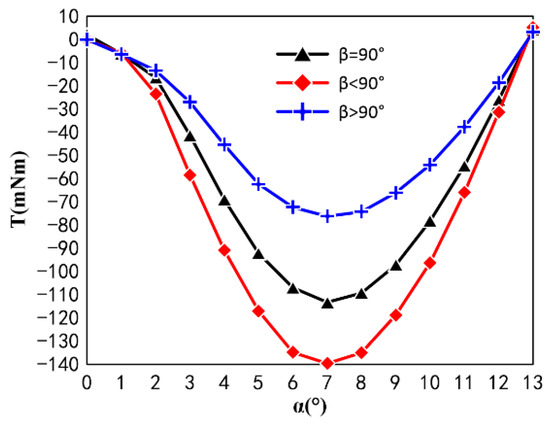
Figure 12.
Cogging torque waveforms of CPT with different shapes.
The FEM shows that is negatively correlated with the cogging torque peak and is in the same phase. Therefore, in the process of designing CPMLTM, the design is to be sharply angled in order to increase the peak slot torque.
In order for the CPMLTM to have positive magnetic stiffness and be able to perform automatic neutral adjustment, the first half-cycle of the cogging torque waveform must be in the negative phase. According to the expression of the cogging torque of CPMLTM, the pole arc coefficient and the slot opening coefficient affect the phase of the cogging torque waveform. In order to ensure that the CPMLTM can perform automatic neutral adjustment, it is necessary to select the suitable pole arc coefficient and slot opening coefficient. In practice, the arc factor is usually set to 0.8 to improve the utilization of PM, so this study only investigates the effect of different slot opening factors on the phase of the cogging torque waveform when the arc factor is 0.8.
Using FEM, the simulation model of CPMLTM with 14 poles and 14 slots was established, and the cogging torque waveforms of CPMLTM with slot opening coefficients of 0.1, 0.2, 0.3, 0.4, and 0.5 were calculated, as shown in Figure 13.
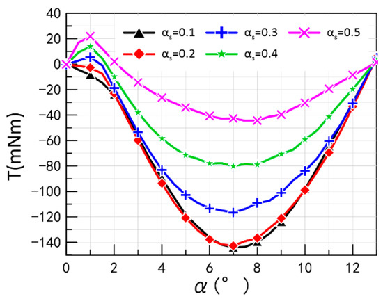
Figure 13.
Cogging torque waveforms with different slot opening coefficients.
It can be found that when the slot opening factor is 0.1 or 0.2, the phase of the cogging torque is negative. When the notch opening factor is greater than 0.3, there is a positive phase of the cogging torque.
4. Sensitivity Analysis of Electromagnetic Torque to Design Parameters
Electromagnetic torque has always been one of the most important performance indicators of torque motors. In engineering applications, the equivalent magnetic circuit method is often used to calculate the electromagnetic torque, but this method often assumes that the permeability of the magnetically conductive material is infinite, and that by default there is no magnetic leakage, so the value of the electromagnetic torque cannot be accurately derived. Moreover, there is a non-negligible magnetic leakage between the PMs and between the teeth of each claw pole.
In order to derive the electromagnetic torque of CPMLTM more accurately and to analyze its sensitivity to each design parameter. This study will first derive the qualitative equations for the electromagnetic torque of CPMLTM to derive the design parameters associated with the electromagnetic torque. Then, an orthogonal test will be designed to calculate the electromagnetic torque using FEM to analyze the sensitivity of the design parameters.
4.1. Electromagnetic Torque Analysis
The equivalent magnetic circuit model proposed in this study ignores each leakage and scattered magnetism, neglects the magnetic voltage drop at the stator claw pole, and considers only the radial main flux. Considering the symmetry of the structure, only the model of torque motor 1/14 is presented in this study. The equivalent magnetic circuit model is shown in Figure 14.
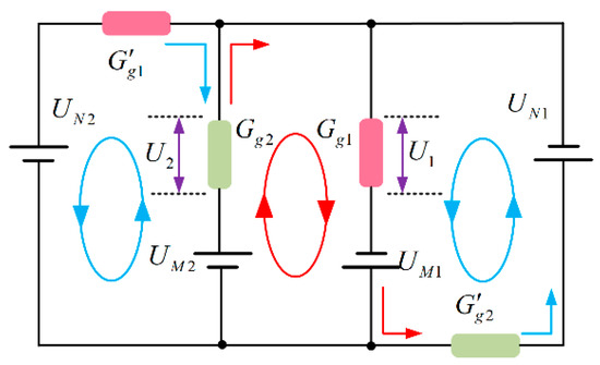
Figure 14.
Equivalent Magnetic Circuit Model of Electromagnetic Torque.
The magnetic circuit is similar to the circuit [37,38]. According to Kirchhoff’s law, the MMF generated by the PM and the control coil alone excitation is as follows
where is the MMF generated by the PM, is the MMF generated by the coil winding, and is the working air gap permeability.
The working air gap is shown in Figure 15, where is the slot opening, is the slot spacing, is the PM spacing, is the slot width between PMs, is the overlap angle at neutral, is the number of slots, is the number of pole pairs, is the CPT length, is the air gap thickness, is the claw pole outer diameter, is the pole arc coefficient, and is the slot opening coefficient.
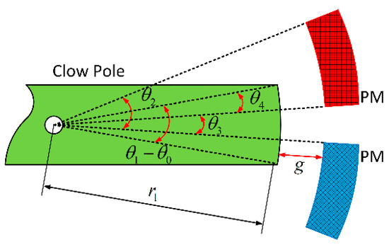
Figure 15.
Structure diagram of working air gap.
The overlap angle at the neutral position can be found from the working air gap structure diagram as .
The expression for the air gap permeability is
where
Under the action of the polarized magnetic field and control magnetic field, the MMF of the working air gap is shown in Equation (15), the sum of the magnetic co-energy of the working air gap is shown in Equation (16), and the expression of static torque is obtained after the derivation of magnetic co-energy is shown in Equation (17).
For , and the torque motor operating range, its rotor is always rotating near the neutral position, so the equation can be further reduced to
where
where is the air gap permeability, is the magnetic potential generated by the magnet, is the number of turns of the coil, and is the current.
It can be seen from the expression that design parameters such as CPT arc, working air gap thickness, magnet arc, magnet thickness, and magnet pitch arc all have an effect on the electromagnetic torque of the claw pole torque motor.
4.2. Sensitivity Analysis of Design Parameters Based on Orthogonal Test
The electromagnetic torque model derived from the equivalent magnetic circuit is an ideal model that ignores the leakage and magnetic saturation, and cannot accurately derive the actual effect of each parameter change on the electromagnetic torque. In contrast, the FEM can accurately calculate the electromagnetic torque of the CPMLTM for various design parameters because there are many design parameters that have an effect on the electromagnetic torque. Therefore, several simulations are required to derive the actual effect of each design parameter on the electromagnetic torque.
Based on the qualitative equations of electromagnetic torque derived in the previous paper, , , , and are all used as adjustable factors in this paper. Each factor is designed with four different levels. If each level of each factor is paired with each other for a full test, 45 = 1024 trials are required. However, each 3D electromagnetic finite element simulation often takes a long time, so conducting too many tests can be computationally consuming and time consuming.
In order to reduce the number of tests as much as possible without affecting the experimental effect, this paper intends to use the orthogonal test method to analyze the sensitivity of the claw-pole torque motor. The orthogonal test design method is an efficient, economical and fast design method for studying multi-factor and multi-level problems.
In this paper, a 5-factor, 4-level orthogonal test was designed with electromagnetic torque as the test index and , , , and as the adjustable factors. The configuration of the levels according to the adjustable factors is shown in Table 2.

Table 2.
Adjustable factor level configuration table.
The number of levels of each factor in the orthogonal table designed in this paper is equal and is called the equal level orthogonal table, denoted by the symbol . is the symbol of the orthogonal table; is the number of rows of the orthogonal table, which is the number of trials required; is the number of factor levels; is the number of columns, which is the number of factors. In this paper, a 5-factor, 4-level orthogonal table was designed for , as shown in Table 2.
The analysis methods often used in orthogonal tests are analysis of variance and analysis of extreme variance. Analysis of extreme variance is a very practical analysis method because of its simplicity and small computational effort. Generally, the sensitivity of the design parameters is reflected by the extreme difference analysis, and the larger the extreme difference value is, the greater the influence of the design parameters on the test results. According to the orthogonal table, the FEM is used to simulate 16 groups of torque motors and perform the analysis of extreme deviation on them, as shown in Table A1.
In the table, denotes the sum of test results corresponding to a level number on any column; is the extreme difference, which can be calculated by Equation (20) on any column
From the table, we can see that the extreme difference value of PM thickness is 0.0036 Nm, the extreme difference value of air gap thickness is 0.1093 Nm, the extreme difference value of slot opening coefficient is 0.0707 Nm, the extreme difference value of arc coefficient is 0.0083 Nm, and the extreme difference value of CPT length is 0.0912 Nm. The order of sensitivity is: air gap thickness > CPT length > slot opening coefficient > arc coefficient > PM thickness.
Figure 16 gives the curves of the variation of the values for each factor at each level. From the curves, it can be seen that the effect of PM thickness and pole arc coefficient on the electromagnetic torque of CPMLTM is extremely small and negligible. However, the expression of electromagnetic torque derived from the equivalent magnetic circuit method shows that the PM thickness and pole arc coefficient are crucial and positively correlated with the electromagnetic torque. The results obtained from the simulation tests are different from those obtained by the equivalent magnetic circuit method because of the large saturation of the polarized flux generated at all levels of the PMs selected for this paper, whereas the equivalent magnetic circuit method assumes that there is no magnetic saturation in the magnetic circuit.
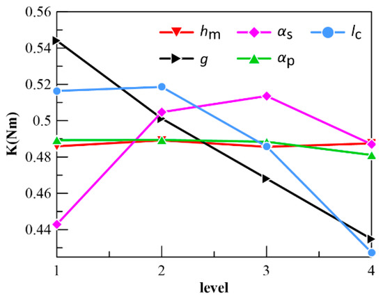
Figure 16.
The curves of the variation of K values for each factor at each level.
The following conclusions can also be drawn from the expression for the electromagnetic torque derived from the equivalent magnetic circuit method: the smaller the air gap thickness, the greater the electromagnetic torque; the slot opening factor is negatively related to the electromagnetic torque; the longer the CPT, the greater the electromagnetic torque. However, the conclusion from the simulation test is different from these conclusions. The curve shows that the value increases and then decreases when the slot opening factor increases, and the value remains the same and then decreases when the length of the CPT increases. This is because when the slot opening factor is too small, there will be a large amount of magnetic leakage between the two CPTs, which will seriously affect the electromagnetic torque and cause it to decrease; when the length of the CPT increases, the magnetic leakage between the end of the CPT and the end of the other claw machine will gradually increase and the electromagnetic torque cannot increase or decrease.
5. Experimental Study
5.1. Prepare for the Experiment
Based on the theoretical analysis of cogging torque and electromagnetic torque, a CPMLTM prototype was fabricated by selecting a suitable claw-pole tooth shape, suitable polar arc coefficient, and slot opening coefficient, as shown in Figure 17. Three test rigs were built to verify the principle of CPMLTM in order to measure the cogging torque, electromagnetic torque, axial recovery force, step characteristics, angular amplitude, amplitude frequency characteristics, and phase frequency characteristics of the prototype. The static test rig is shown in Figure 18, which is used to measure the cogging torque, electromagnetic torque, and axial recovery force of the prototype. The angular test rig, shown in Figure 19, is used to measure the actual rotation angle of the prototype. The dynamic test rig shown in Figure 20 is used to measure the step response, amplitude frequency characteristics, and phase frequency characteristics of the prototype.
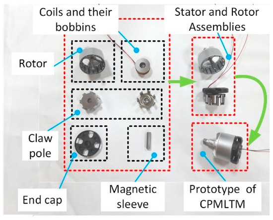
Figure 17.
Prototype of CPMLTM.
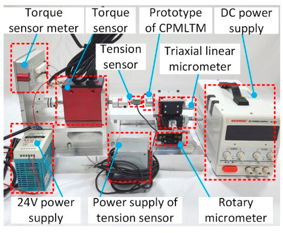
Figure 18.
The static test rig.
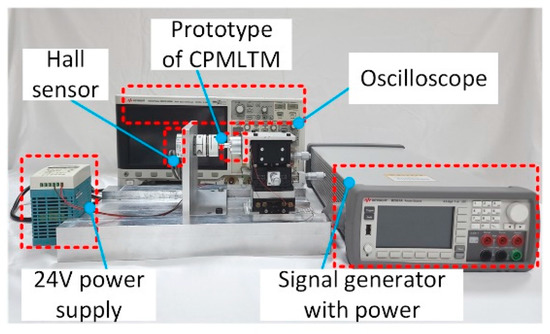
Figure 19.
The angular test rig.
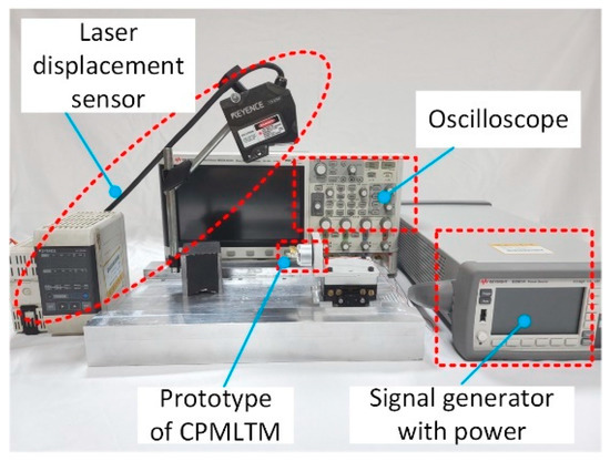
Figure 20.
The dynamic test rig.
The static test rig consists of a signal generator with power, a rotary micrometer, a triaxial linear micrometer, a prototype, a tension sensor and its power supply, a torque sensor and its display, and a 24 V DC power supply. One end of the torque sensor is fixed to the test rig, and the other end is connected to the rotor of the prototype through the tension sensor. The stator of the prototype is connected to the triaxial linear micrometer and rotating micrometer at one end, and the other end is assembled with the rotor shaft gap. The rotary micrometer and triaxial linear micrometer can be adjusted to produce direct motion and rotation of the prototype stator to imitate the actual working conditions of the prototype in the 2D valve.
During the measurement of the electromagnetic torque, a signal generator with power transmits the signal to the stator coil. The electromagnetic torque is generated between the stator and rotor, and the rotor transmits the torque to the torque sensor via the pull-pressure sensor. The torque sensor receives the torque, generates a voltage signal, and transmits it to the display meter, which converts the voltage signal into a torque value and displays it. The measurement process of the cogging torque and axial recovery force is similar to the process mentioned above.
Figure 19 shows the angle measurement test rig. The test rig consists of a prototype, a Hall sensor, a signal generator with power, and an oscilloscope. One end of the Hall sensor is fixed to the rotor of the prototype by a coupling, and the other end is bolted to the rig. The oscilloscope is connected to both the signal generator with power and the Hall sensor to receive, analyze and store the input current signal and the output voltage signal representing the angular displacement. The signal generator outputs a sinusoidal signal when measuring the actual rotation angle.
During the experimental measurement, the coaxiality between the stator, rotor, pull-pressure sensor, and torque sensor can seriously affect the accuracy of the measurement. In this study, the coaxiality of the stator, rotor, tension sensor, and torque sensor is ensured by adjusting the rotary micrometer and the triaxial linear micrometer. Adjusting the triaxial linear micrometer ensures that the axes are flush in the x-axis, y-axis, and z-axis directions. During the experiment, the center of rotation of the rotary micrometer coincides with the axis of the prototype, thus ensuring that the prototype axis is always stationary during the rotation of the prototype.
The dynamic characteristics of the prototype could not be accurately measured using the test rig shown in Figure 19 because of the large rotational inertia of the coupling and Hall sensor as a whole. A laser displacement sensor is needed to measure the dynamic characteristics of the prototype. Therefore, a test rig was built specifically to measure the dynamic characteristics of the prototype, as shown in Figure 20. The test rig consists of a prototype, a copper plate fixed to the rotor of the prototype, a laser displacement sensor, a signal generator with power, and an oscilloscope. The copper piece fixed on the rotor of the prototype is used to reflect the laser signal emitted from the laser displacement sensor. The oscilloscope is connected to both the signal generator with power and the laser displacement sensor to receive, analyze and store the input current signal and the output voltage signal representing the displacement. When measuring the step and frequency response characteristics, the signal generator outputs a step signal and a sinusoidal signal, respectively.
5.2. Static Experiment
Firstly, the cogging torque angle characteristics of CPMLTM are measured to determine whether it has the function of automatic neutral adjustment in the circumferential direction. The experimental results of the prototype are compared with the finite element simulation results, as shown in Figure 21. It can be found that the experimental results are in good agreement with the simulation results. The torque angle characteristics of the cogging torque show that the first half of the waveform near the neutral position is in the negative phase, i.e., the direction of the cogging torque is opposite to the direction of the circumferential motion. Therefore, it can be verified that the CPMLTM proposed in this paper does have the function of automatic circumferential neutral adjustment.
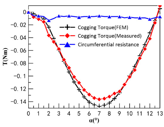
Figure 21.
The cogging torque angle characteristics of CPMLTM, Circumferential angular displacement_Circumferential resistances.
The CPMLTM is capable of automatic neutral adjustment in both circumferential and axial directions. The coil is not energized and the axial recovery force between the stator and rotor of the prototype at different axial displacements is measured by adjusting the triaxial linear micrometer. A comparison of the test data with the simulation data is shown in Figure 22. The comparison of curves shows that the experimental results are in good agreement with the simulated results. When the rotor deviates axially from the neutral position from any direction, the axial force applied to the rotor is in the opposite direction of the axial displacement. Therefore, it can be verified that the torque motor proposed in this study can achieve the function of automatic axial neutral adjustment and reset.
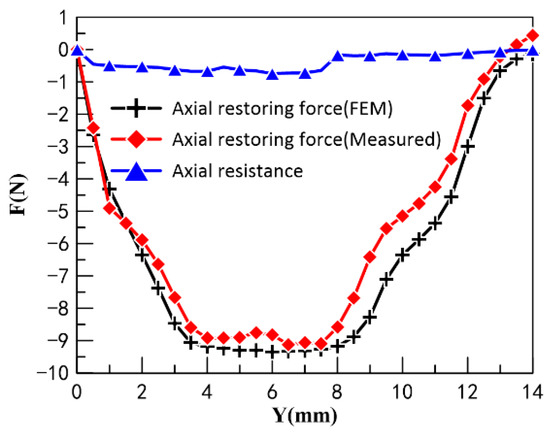
Figure 22.
Axial displacement_axial restoring force, Axial displacement_axial resistances.
In the process of measuring the cogging torque and axial recovery force, there is additional circumferential and axial resistance that affects the measurement accuracy because of factors such as friction between the test stand and the prototype. Therefore, in this study, the circumferential and axial resistances between the prototype and the test rig were measured to analyze whether the resistances would seriously affect the accuracy of the experiment. The resistance was measured by removing the PM from the rotor of the prototype so that there was no cogging torque and axial restoring force between the stator and the rotor. The measured results of the circumferential and axial resistances are shown in Figure 21 and Figure 22, respectively. According to the experimental results, it can be found that the circumferential and axial resistances are much smaller than the cogging torque and axial recovery force, which will not affect the accuracy of the experiment.
The CPMLTM is not only capable of automatic neutral adjustment, but also has a higher accuracy of neutral adjustment than conventional torque motors. In this study, we measured and plotted the no-load angular displacement curves of two torque motors to compare the accuracy of their neutral adjustment. The zeroing screw and zeroing spring were adjusted to ensure that the four working air gaps between the armature and the pole shoe were equal in thickness before the experiments were conducted on the conventional torque motor to achieve manual neutral adjustment. The no-load angular displacement curve is based on the input current for the horizontal coordinate and the output angular displacement for the vertical coordinate. The experimental data are dimensionless, and the angular displacement curves of CPMLTM and the conventional torque motor are shown in Figure 23. The trajectory of the midpoint of the angular displacement curve is called the nominal angular displacement curve, and the ratio between the input current value and the rated current required to keep the torque motor in the neutral position is called its zero bias. The zero bias of the torque motor reflects the accuracy of its neutral adjustment, and the zero bias of the CPMLTM is 0.9%, compared to 32.5% for the conventional torque motor. The zero bias of CPMLTM is smaller than that of conventional torque motors, which can prove that the accuracy of CPMLTM is significantly higher than that of the conventional torque motor.
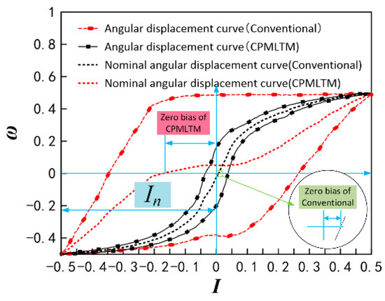
Figure 23.
Angular displacement curve.
The electromagnetic torque is a crucial index of the torque motor. Figure 24 gives the electromagnetic torque angle characteristic curve of CPMLTM. When measuring the electromagnetic torque moment angle characteristic, the magnetic potential generated after the coil is energized is 100 A. It can be found that the difference between the experimental data and the simulation gradually increases with the increase of the turning angle, which is because the coaxiality between the torque sensor, the tension sensor, and the prototype cannot be guaranteed, so the error will be generated during the rotation.
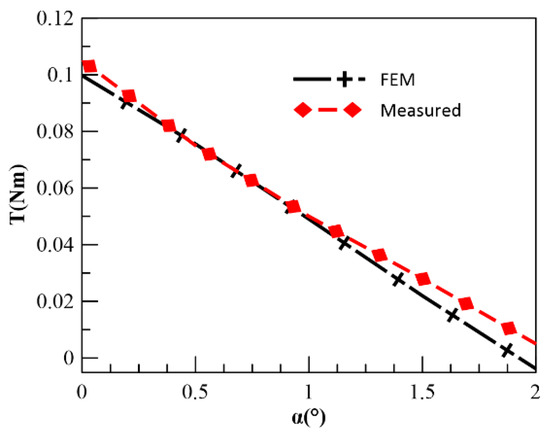
Figure 24.
The electromagnetic torque angle characteristic curve of CPMLTM.
When the rotor is in the neutral position, the relationship between the coil MMF and the electromagnetic torque is shown in Figure 25. It can be seen that the experimental results are in good agreement with the simulation results. When the input MMF exceeds 100 A, the increase of the electromagnetic torque of CPMLTM slows down as the coil MMF increases. Combined with the magnetic field density cloud of the CPMLTM shown in Figure 26, it is known that this result is due to the saturation of the magnetic field in the claw pole.
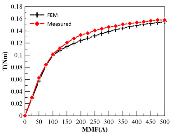
Figure 25.
The relationship between the MMF and the electromagnetic torque.
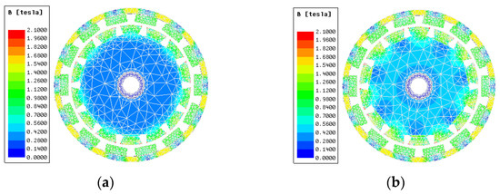
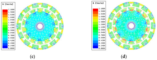
Figure 26.
The magnetic field density cloud of the CPMLTM. (a) 0 A, (b) 50 A, (c) 100 A, (d) 150 A.
The effect of axial displacement on the output angular displacement was investigated experimentally because the CPMLTM produces axial motion simultaneously with the circumferential motion. Figure 27 shows the effect of axial displacement on the output electromagnetic torque for 0°, 0.2°, 0.4°, 0.6°, 0.8°, and 1° of circumferential angular displacement. The experiments show that the axial and circumferential motions of CPMLTM do not interfere with each other.
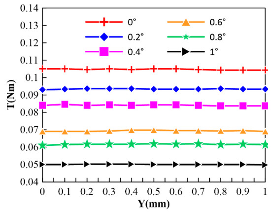
Figure 27.
Diagram of the effect of axial displacement on the output electromagnetic torque.
During the measurement of the actual rotation angle, a sinusoidal signal is fed to the prototype coil through a signal generator. The Hall sensor measures the angular displacement in real time during the rotor rotation of the prototype. The input and output signals from the oscilloscope are analyzed to obtain the relationship between the actual rotation angle of the prototype and the MMF of the coil, as shown in Figure 28.
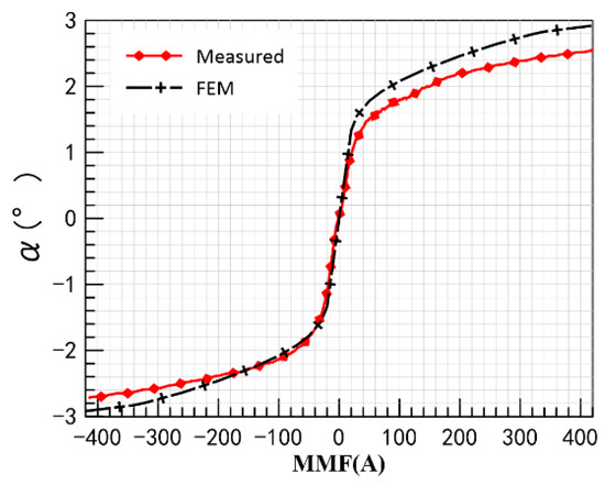
Figure 28.
MMF_actual rotation angle.
By comparing the simulated data with the experimental results, it can be found that the simulated data and the experimental results are in high agreement when the MMF is small; as the MMF grows, the error between the experimental results and the simulated data gradually increases. This is because the permeability of the actual material is lower than that of the ideal material in the simulation. From Figure 28, it can be seen that when MMF is in the range of −40 A to 40 A, there is good linearity between the actual rotation angle of the prototype and MMF. The actual rotation angle of the rotor is 1.405° when MMF is 40 A and 1.589° when MMF is −40 A. The asymmetry of the actual rotation angle is due to the error in the prototype machining and assembly process, which leads to the unequal spacing between the jaw pole teeth.
5.3. Dynamic Experiment
The dynamic characteristics experiments of CPMLTM mainly include step response characteristics experiments and frequency response characteristics experiments, both of which can be tested using the experimental rig shown in Figure 20. The step currents of 0.156 A, 0.312 A, and 0.624 A are input to CPMLTM, and the effects of different input currents on the step characteristics of CPMLTM are obtained, as shown in Figure 29. It can be found that for all the step signals, the overshoot amount exists in both simulation and experiment. The reason for the overshoot may be that the CPMLTM is experimented with no load and less damping. The magnitude of the step current affects the step response of the CPMLTM. The response times corresponding to the step currents of 0.156 A, 0.312 A, and 0.624 A input are 5.4 ms, 4.875 ms, and 4.575 ms, respectively.
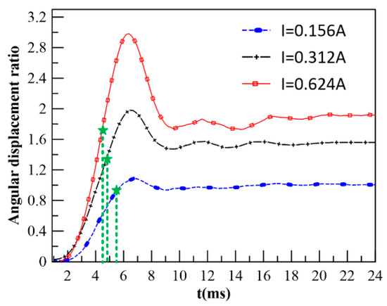
Figure 29.
Step response characteristics.
The experimental results of the frequency characteristics of CPMLTM are shown in Figure 30. In the experimental results, 1 Hz and 10 Hz maintain good following characteristics with a small phase lag and no attenuation of amplitude. At 40 Hz, the experimental curve shows small phase lag and obvious attenuation of amplitude. At 80 Hz, the experimental curve shows large phase and amplitude lag and attenuation, but the phase does not lag more than 90° and the amplitude does not attenuate more than −3 dB. The amplitude and frequency characteristic curves of CPMLTM are plotted according to the dynamic experimental results, as shown in Figure 31. When the amplitude ratio is −3 dB, the experimental amplitude frequency width is 173.7 Hz, and when the phase lag is 90°, the experimental phase frequency width is 86.5 Hz, which shows that CPMLTM has good dynamic characteristics.
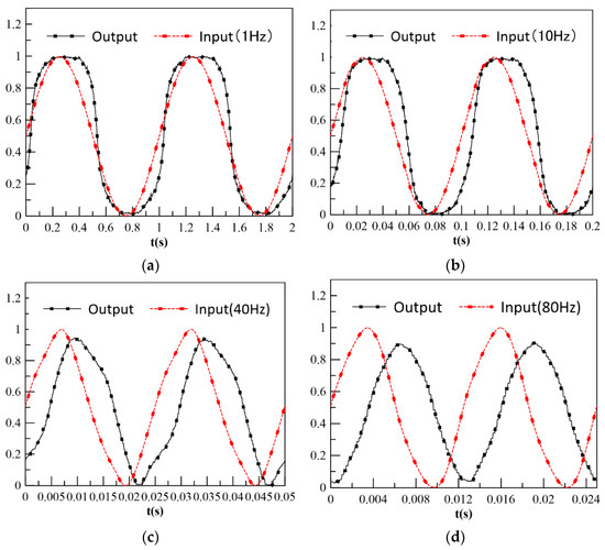
Figure 30.
Sine wave following characteristics of CPMLTM. (a) 1 Hz, (b) 10 Hz, (c) 40 Hz, (d) 80 Hz.
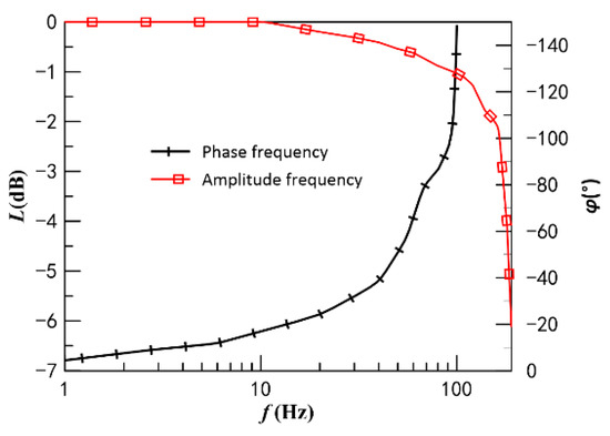
Figure 31.
Frequency response characteristics.
6. Conclusions
(1) A new type of CPMLTM for 2D valves using cogging torque is proposed. CPMLTM is capable of automatically levitating in the circumferential and axial neutral positions using the cogging torque and magnetic force between the stator and rotor.
(2) The cogging torque of CPMLTM was analyzed. The effects of CPT shape and slot opening coefficient on the cogging torque waveform of CPMLTM were investigated.
(3) The sensitivity of the electromagnetic torque to the design parameters is investigated. The qualitative expression of electromagnetic torque is derived from the equivalent magnetic circuit method to obtain the design parameters related to electromagnetic torque; a set of orthogonal tests was designed and the FEM was used to calculate the electromagnetic torque. The sensitivity ranking of electromagnetic torque to design parameters is obtained by polar difference analysis: air gap thickness > CPT length > slot opening coefficient > arc coefficient > PM thickness.
(4) A prototype was fabricated and three test rigs were built to measure the cogging torque, electromagnetic torque, axial recovery force, step characteristics, angular amplitude, amplitude frequency characteristics, and phase frequency characteristics. The experimental results show that the CPMLTM has good static and dynamic characteristics. The neutral electromagnetic torque is 0.1 Nm when the coil MMF is 100 A; the step response time can reach 4.575 ms, and the amplitude frequency bandwidth and phase frequency bandwidth are 173.7 Hz and 86.5 Hz, respectively.
Author Contributions
Conceptualization, J.R.; methodology, J.H.; formal analysis, J.H.; investigation, Z.S.; resources, J.R.; software, J.H. and S.X.; validation, J.H.; data curation, Z.S.; writing—original draft preparation, J.H. and S.X.; writing—review and editing, J.R. and S.L.; supervision, J.R.; project administration, S.L. and J.R.; funding acquisition, S.L. and J.R. All authors have read and agreed to the published version of the manuscript.
Funding
This research was funded by the National Key Research and Development Program, China, grant number: 2019YFB2005201.
Institutional Review Board Statement
Not applicable.
Informed Consent Statement
Not applicable.
Data Availability Statement
Not applicable.
Conflicts of Interest
The authors declare no conflict of interest.
Abbreviations
The following abbreviations are used in this manuscript:
| 2D | Two-dimensional |
| EMC | Electro-mechanical converter |
| FEM | Finite element Method |
| CPMLTM | Claw-pole magnetic levitation torque motor |
| MMF | Magnetomotive force |
| PM | Permanent magnet |
| CPT | Claw pole tooth |
Nomenclature
| angular displacement | |
| magnetic co-energy | |
| the angle between the centerline of the PM and the centerline of the claw-pole slot | |
| current | |
| current factor | |
| magnetic spring stiffness factor | |
| the angle between the side of the claw pole tooth and the bottom of the slot (i = 1,2,3) | |
| the air permeability | |
| Distance from PM centerline in radians | |
| Distance in radians from the centerline of the claw pole slot | |
| the distribution of the residual flux density of the PM along the perimeter of the air gap | |
| the thickness of the PM along the magnetization direction | |
| the distribution function of the effective air gap length | |
| the number of pole pairs | |
| the slot number | |
| the residual flux density of the PM | |
| the pole arc coefficient | |
| the slot opening coefficient | |
| the opening of the claw pole slot in meters | |
| the slot opening in radians | |
| the slot pitch in radians | |
| the PM spacing | |
| the slot width between PMs | |
| the overlap angle at neutral | |
| the effective air gap length within half the claw pole slot distance | |
| the axial length of the CPT | |
| the outer diameter of the claw pole | |
| the inner diameter of the shell | |
| the MMF generated by the PM | |
| the MMF generated by the coil winding | |
| the working air gap permeability | |
| the number of slots | |
| the CPT length | |
| the air gap thickness | |
| equal level orthogonal table | |
| the symbol of the orthogonal table | |
| the number of rows of the orthogonal table | |
| the number of factor levels | |
| the number of columns | |
| the sum of test results corresponding to a level number i on any column | |
| the extreme difference |
Appendix A

Table A1.
Orthogonal test results table.
Table A1.
Orthogonal test results table.
| Factor | Test Index | ||||||
|---|---|---|---|---|---|---|---|
| Test Number | |||||||
| 1 | 1.3 | 0.3 | 0.1 | 0.9 | 7.7 | 0.1326 | |
| 2 | 1.3 | 0.4 | 0.2 | 0.8 | 8.7 | 0.1379 | |
| 3 | 1.3 | 0.5 | 0.3 | 0.7 | 9.7 | 0.1234 | |
| 4 | 1.3 | 0.6 | 0.4 | 0.6 | 10.7 | 0.092 | |
| 5 | 1.4 | 0.3 | 0.2 | 0.7 | 10.7 | 0.1264 | |
| 6 | 1.4 | 0.4 | 0.1 | 0.6 | 9.7 | 0.113 | |
| 7 | 1.4 | 0.5 | 0.4 | 0.9 | 8.7 | 0.126 | |
| 8 | 1.4 | 0.6 | 0.3 | 0.8 | 7.7 | 0.1238 | |
| 9 | 1.5 | 0.3 | 0.3 | 0.6 | 8.7 | 0.1487 | |
| 10 | 1.5 | 0.4 | 0.4 | 0.7 | 7.7 | 0.1326 | |
| 11 | 1.5 | 0.5 | 0.1 | 0.8 | 10.7 | 0.0913 | |
| 12 | 1.5 | 0.6 | 0.2 | 0.9 | 9.7 | 0.113 | |
| 13 | 1.6 | 0.3 | 0.4 | 0.8 | 9.7 | 0.1364 | |
| 14 | 1.6 | 0.4 | 0.3 | 0.9 | 10.7 | 0.1177 | |
| 15 | 1.6 | 0.5 | 0.2 | 0.6 | 7.7 | 0.1274 | |
| 16 | 1.6 | 0.6 | 0.1 | 0.7 | 8.7 | 0.106 | |
| K1 | 0.4859 | 0.5441 | 0.4429 | 0.4893 | 0.5164 | ||
| K2 | 0.4892 | 0.5012 | 0.5047 | 0.4894 | 0.5186 | ||
| K3 | 0.4856 | 0.4681 | 0.5136 | 0.4884 | 0.4858 | ||
| K4 | 0.4875 | 0.4348 | 0.487 | 0.4811 | 0.4274 | ||
| R | 0.0036 | 0.1093 | 0.0707 | 0.0083 | 0.0912 | ||
Appendix B
References
- Chao, Q.; Zhang, J.H.; Xu, B.; Huang, H.P.; Pan, M. A Review of High-Speed Electro-Hydrostatic Actuator Pumps in Aerospace Applications: Challenges and Solutions. J. Mech. Des. 2019, 141, 050801. [Google Scholar] [CrossRef]
- Liu, Y.; Wang, T.; Gong, G.F.; Gao, R.J. Present Status and Prospect of High-Frequency Electro-hydraulic Vibration Control Technology. Chin. J. Mech. Eng. 2019, 32, 93. [Google Scholar] [CrossRef]
- Xu, B.; Shen, J.; Liu, S.; Su, Q.; Zhang, J. Research and Development of Electro-hydraulic Control Valves Oriented to Industry 4.0: A Review. Chin. J. Mech. Eng. 2020, 33, 13–32. [Google Scholar] [CrossRef]
- Zhao, J.A.; Fu, Y.; Ma, J.; Fu, J.; Chao, Q.; Wang, Y. Review of cylinder block/valve plate interface in axial piston pumps: Theoretical models, experimental investigations, and optimal design. Chin. J. Aeronaut. 2021, 34, 111–134. [Google Scholar] [CrossRef]
- Mao, Z.B.; Asai, Y.; Yamanoi, A.; Seki, Y.; Wiranata, A.; Minaminosono, A. Fluidic rolling robot using voltage-driven oscillating liquid. Smart Mater. Struct. 2022, 31, 105006. [Google Scholar] [CrossRef]
- Fang, Y.; Zhang, J.H.; Xu, B.; Mao, Z.B.; Li, C.M.; Huang, C.S.; Lyu, F.; Guo, Z.M. Raising the Speed Limit of Axial Piston Pumps by Optimizing the Suction Duct. Chin. J. Mech. Eng. 2021, 34, 105. [Google Scholar] [CrossRef]
- Elbayomy, K.M.; Jiao, Z.X.; Zhang, H.Q. PID controller optimization by GA and its performances on the electro-hydraulic servo control system. Chin. J. Aeronaut. 2008, 21, 378–384. [Google Scholar] [CrossRef]
- Zhang, C.C.; Zhu, C.H.; Meng, B.; Li, S. Challenges and Solutions for High-Speed Aviation Piston Pumps: A Review. Aerospace 2021, 8, 392. [Google Scholar] [CrossRef]
- Amirante, R.; Distaso, E.; Tamburrano, P. Sliding spool design for reducing the actuation forces in direct operated proportional directional valves: Experimental validation. Energy Convers. Manag. 2016, 119, 399–410. [Google Scholar] [CrossRef]
- Yan, H.; Wang, F.J.; Li, C.C.; Huang, J. Research on the jet characteristics of the deflector-jet mechanism of the servo valve. Chin. Phys. B 2017, 26, 044701. [Google Scholar] [CrossRef]
- Lu, L.; Long, S.R.; Zhu, K.W. A Numerical Research on Vortex Street Flow Oscillation in the Double Flapper Nozzle Servo Valve. Processes 2019, 7, 721. [Google Scholar] [CrossRef]
- Li, S.J.; Peng, J.H.; Zhang, S.Z.; McHenya, J.M. Depression of Self-Excited Pressure Oscillations and Noise in the Pilot Stage of a Hydraulic Jet-pipe Servo-Valve using Magnetic Fluids. In Proceedings of the International Conference on Applied Materials and Electronics Engineering (AMEE 2012), Hong Kong, China, 18–19 January 2012. [Google Scholar]
- Wang, B.; Du, Y.H.; Ye, Z.F. Excitation of Piezoelectrically Actuated Nozzle-Flapper Valve and Its Potential for Fuel Flowmeter Dynamic Calibration. IEEE/ASME Trans. Mechatron. 2020, 25, 848–858. [Google Scholar] [CrossRef]
- Ruan, J.; Burton, R.; Ukrainetz, P.; Xu, Y.M. Two-dimensional pressure control valve. Proc. Inst. Mech. Eng. Part C J. Mech. Eng. Sci. 2001, 215, 1031–1039. [Google Scholar] [CrossRef]
- Ruan, J.; Burton, R.; Ukrainetz, P. An investigation into the characteristics of a two dimensional “2D” flow control valve. J. Dyn. Syst. Meas. Control 2002, 124, 214–220. [Google Scholar] [CrossRef]
- Ruan, J.; Burton, R.T. An electrohydraulic vibration exciter using a two-dimensional valve. Proc. Inst. Mech. Eng. Part I J. Syst. Control Eng. 2009, 223, 135–147. [Google Scholar] [CrossRef]
- Zhang, Q.; Yan, L.; Duan, Z.; Jiao, Z.; Gerada, C.; Chen, I.M. High Torque Density Torque Motor with Hybrid Magnetization Pole Arrays for Jet Pipe Servo Valve. IEEE Trans. Ind. Electron. 2020, 67, 2133–2142. [Google Scholar] [CrossRef]
- Yu, G.D.; Xu, Y.X.; Lin, T.Y.; Xiao, L.J.; Zou, J.B.; Tan, J.B. Nonlinear EMC Modeling and Analysis of Permanent-Magnet Slotted Limited-Angle Torque Motor. IEEE Trans. Ind. Electron. 2021, 68, 8507–8518. [Google Scholar] [CrossRef]
- Wu, S.; Zhao, X.Y.; Li, X.; Luk, P.C.K.; Jiao, Z.X. Preliminary Design and Optimization of Toroidally Wound Limited Angle Servo Motor Based on a Generalized Magnetic Circuit Model. IEEE Trans. Magn. 2016, 52, 8205209. [Google Scholar] [CrossRef]
- Meng, L.K.; Zhu, Y.C.; Ling, J.; Ding, J.J.; Chen, Z.C.; Chen, X.M. Research on mathematical modeling of the servo valve torque motor considering the variation of working air-gaps leakage flux. Proc. Inst. Mech. Eng. Part C J. Mech. Eng. Sci. 2022, 236, 6347–6362. [Google Scholar] [CrossRef]
- Xu, D.; Jiang, X.F.; Tu, Y.X.; Li, N.; Li, Q. Investigation of cogging torque reduction for a 6/10 hybrid axial field flux-switching permanent magnet machine by harmonic field current injection. IET Electr. Power Appl. 2020, 14, 2499–2506. [Google Scholar] [CrossRef]
- Li, Z.; Yu, X.Z.; Wang, X.T.; Xing, X.X. Optimization and Analysis of Cogging Torque of Permanent Magnet Spherical Motor. IEEE Trans. Appl. Supercond. 2021, 31, 5204705. [Google Scholar] [CrossRef]
- Simon-Sempere, V.; Simon-Gomez, A.; Burgos-Payan, M.; Cerquides-Bueno, J.R. Optimisation of Magnet Shape for Cogging Torque Reduction in Axial-Flux Permanent-Magnet Motors. IEEE Trans. Energy Convers. 2021, 36, 2825–2838. [Google Scholar] [CrossRef]
- El-Refaie, A.M.; Jahns, T.M.; Novotny, D.W. Analysis of surface permanent magnet machines with fractional-slot concentrated windings. IEEE Trans. Energy Convers. 2006, 21, 34–43. [Google Scholar] [CrossRef]
- Xiao, L.Y.; Li, J.; Qu, R.H.; Lu, Y.; Zhang, R.; Li, D.W. Cogging Torque Analysis and Minimization of Axial Flux PM Machines with Combined Rectangle-Shaped Magnet. IEEE Trans. Ind. Appl. 2017, 53, 1018–1027. [Google Scholar] [CrossRef]
- Koh, C.S.; Seol, J.S. New cogging-torque reduction method for brushless permanent-magnet motors. IEEE Trans. Magn. 2003, 39, 3503–3506. [Google Scholar]
- Wang, D.H.; Peng, C.; Wang, B.D.; Feng, Z.K.; Li, J.C. Permanent Magnet Synchronous Machines with Nonuniformly Distributed Teeth. IEEE Trans. Ind. Electron. 2022, 69, 8705–8715. [Google Scholar] [CrossRef]
- Tong, W.M.; Li, S.Q.; Pan, X.L.; Wu, S.N.; Tang, R.Y. Analytical Model for Cogging Torque Calculation in Surface-Mounted Permanent Magnet Motors with Rotor Eccentricity and Magnet Defects. IEEE Trans. Energy Convers. 2020, 35, 2191–2200. [Google Scholar] [CrossRef]
- Zhu, Z.Q.; Wu, L.J.; Jamil, M.L.M. Influence of Pole and Slot Number Combinations on Cogging Torque in Permanent-Magnet Machines with Static and Rotating Eccentricities. IEEE Trans. Ind. Appl. 2014, 50, 3265–3277. [Google Scholar] [CrossRef]
- He, T.R.; Zhu, Z.Q.; Xu, F.; Wang, Y.; Hong, B.; Gong, L.M. Influence of Rotor Eccentricity On Electromagnetic Performance of 2-pole/3-slot PM Motors. IEEE Trans. Energy Convers. 2022, 37, 696–706. [Google Scholar] [CrossRef]
- Li, S.; Ruan, J.; Meng, B. Study on Frequency Response for a 2D Digital Servo Valve. China Mech. Eng. 2011, 22, 215–219. [Google Scholar]
- Meng, B.; Xu, H.; Ruan, J.; Li, S. Theoretical and experimental investigation on novel 2D maglev servo proportional valve. Chin. J. Aeronaut. 2021, 34, 416–431. [Google Scholar] [CrossRef]
- Meng, B.; Zhu, C.H.; Xu, H.; Dai, M.Z.; Li, S. Analytical and Experimental Investigations of Novel Maglev Coupling Based on Opposed Halbach Array for a 2D Valve. Actuators 2021, 10, 61. [Google Scholar] [CrossRef]
- Meng, B.; Dai, M.Z.; Zhu, C.H.; Xu, H.; Jia, W.A.; Li, S. Investigation of Characteristics of a Novel Torque Motor Based on an Annulus Air Gap. Machines 2021, 9, 131. [Google Scholar] [CrossRef]
- Li, Z.W.; Cao, J.; Chang, L.; Li, S.; Ruan, J. Eddy current loss modelling for torque-motors. IET Power Electron. 2022, 15, 368–380. [Google Scholar] [CrossRef]
- Wang, X.H.; Yang, Y.B.; Fu, D.J. Study of cogging torque in surface-mounted permanent magnet motors with energy method. J. Magn. Magn. Mater. 2003, 267, 80–85. [Google Scholar] [CrossRef]
- Meng, B.; Lai, Y.J.; Qiu, X.G. Regulation Method for Torque-Angle Characteristics of Rotary Electric-Mechanical Converter Based on Hybrid Air Gap. Chin. J. Mech. Eng. 2020, 33, 35. [Google Scholar] [CrossRef]
- Meng, B.; Xu, H.; Liu, B.; Dai, M.Z.; Zhu, C.H.; Li, S. Novel Magnetic Circuit Topology of Linear Force Motor for High Energy Utilization of Permanent Magnet: Analytical Modelling and Experiment. Actuators 2021, 10, 32. [Google Scholar] [CrossRef]
Publisher’s Note: MDPI stays neutral with regard to jurisdictional claims in published maps and institutional affiliations. |
© 2022 by the authors. Licensee MDPI, Basel, Switzerland. This article is an open access article distributed under the terms and conditions of the Creative Commons Attribution (CC BY) license (https://creativecommons.org/licenses/by/4.0/).