1. Introduction
Flexure hinge-based planar XY nanopositioning stages in parallel are widely employed in the fields of micro-machining, micro-manipulation, and scanning-based surface metrology, to mention a few of the applications [
1,
2,
3]. For state-of-the-art designs, dual-axial compliant mechanisms are symmetrically constructed by combining several flexure hinges having a single degree-of-freedom (DOF) of planar bending [
4]. For example, four sets of “T”-shape mechanisms were employed in [
4], for a total of 12 leaf-spring flexure hinges, and a combination of the bending motions of all the hinges jointly contributed to the decoupled dual-axial motions for the end-effector. Taking advantage of the right circular flexure hinges, a compound mechanism combining a separated prismatic joint and a parallelogram was developed to construct a decoupled XY nanopositioning stage in [
5].
Although a structural configuration combining flexure hinges with the bending DOF dominates the current design of dual-axial nanopositioning stages, this increases structural complexity and the equivalent moving inertia caused by the employment of multiple flexure hinges [
4,
5]. To reduce structural complexity, simplified non-symmetric mechanisms having only two orthogonal parallelogram mechanisms were developed to guide the dual-axial motions, as reported in [
6,
7]. However, this simplified structure may lead to an unconstrained parasitic motion for the end-effector, which may greatly deteriorate the positioning accuracy of the planar stages. To overcome this defect, an alternative solution might be the adoption of flexure hinges to directly connect the end-effector and the base in a symmetric manner, which may simultaneously simplify the structure and guarantee accurate motion. In this condition, concurrent transition of planar bending and axial stretching deformations is essentially required for the flexure hinges to enable planar motions. As a candidate, “L”-shape flexure linkages are promising, and four sets of “L”-shape linkages may provide symmetric guidance for the motion along the two directions [
8,
9,
10]. However, considering the corner structure of the linkage, it is difficult to arrange a parallel configuration for the multiple linkages to improve the resistance capability.
Recently, the concept of corrugated flexure hinges was developed and applied to construct dual-axial XY nanopositioning stages [
11,
12,
13]. Along with a circular curve segment [
14], a cone-shaped [
15] segment was also developed to enrich the grouping of the corrugated flexural hinges. Following the conventional “T”-shape structure, corrugated hinges have also been applied to construct dual-axial XY nanopositioning stages [
11,
12,
13]. As for those designs, the corrugated hinges were adopted to reduce the stress and extend the deformation range of conventional flexure hinges within a limited space [
14], and the unique stretchable feature has not been explored for motion delivery. Since the “T”-shape structure was adopted for those designs, the resulting corrugated hinge-based planar stages may inevitably have similar defects as aforementioned.
To gain high-performance dual-axial guidance, we develop a dual-axial corrugated flexure mechanism with a simple structure and low moving mass. The main contributions of this study are: (a) A sinusoidal corrugated flexure hinge with a simple mathematical description is developed and comprehensively characterized by both analytical and finite element simulation methods. (b) The unique stretchable property is explored to realize concurrent stretching and bending of the corrugated flexure hinge for dual-axial motion guidance. (c) A corrugated dual-axial flexure mechanism is developed and demonstrated by applying it to a dual-axial electromagnetic stage.
The remainder of this paper is organized as follows:
Section 2 introduces the sinusoidal corrugated hinge and derives its static compliance,
Section 3 presents the developed corrugated dual-axial mechanism, and
Section 4 demonstrates the parameter selection for constructing the dual-axial nanopositioning stage. The experimental testing of mechanism stiffness and the basic performance of the constructed dual-axial stage is detailed in
Section 5, and the main conclusions are drawn in
Section 6.
2. The Sinusoidal Corrugated Flexure Linkage
Although a sinusoidal corrugated beam was developed in [
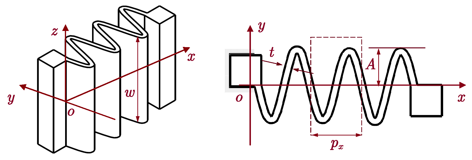
12] to clamp the movers to eliminate under-constraining, the complex stretching and bending property was not investigated for the corrugated beam. Herein, we introduce a monolithic sinusoidal corrugated flexure linkage, and the three-dimensional (3D) structure is illustrated in
Figure 1. Along with the bending property, the linkage is intrinsically stretchable due to the structure corrugation, and multiple cycles may further enhance the flexibility for tuning the stretching stiffness.
Mathematically, the sinusoidal corrugated flexure linkage can be described by a simple and continuous equation as
where
A,
, and
n denote the amplitude, spatial periodicity, and cycle number of the linkage, respectively.
2.1. Stiffness Modeling of the Sinusoidal Corrugated Flexure Linkage
The sinusoidal corrugated linkage shown in
Figure 1 can be decomposed into several (
n) serially connected flexure units (
). Assuming the load and corresponding deformation at the free end of the unit are, respectively,
and
, the bending torques at position
x can be expressed as
and the planar normal and shear force are
with
Therefore, following Castigliano’s second theorem, the elastic strain energy can be expressed as [
16]
where
I is the second moment of the rectangular section of the corrugated beam, and
is the cross-sectional area. In addition,
E represents the Young’s modulus of the material,
is the shear modulus, with
denoting the Passion’s ratio, and
is the shear coefficient.
Accordingly, the spatial six-DOF compliance for the sinusoidal corrugated flexure unit can be obtained as [
16,
17]
By substituting Equations (
1)–(
5) into Equation (
6), the compliance items can be derived, which are presented in detail in
Appendix A. Accordingly, the relationship between the deformations and loads for the flexure unit yields
where the compliance matrix
is defined as
Considering the serially connected flexure units (
n) as shown in
Figure 1, the complete compliance of the sinusoidal corrugated linkage can be derived following matrix-based compliance modeling (MCM) [
18,
19] as
where
is the compliance transformation matrix (CTM) to transfer the local coordinate system of the
i-th flexure unit to the coordinate system of the linkage [
18,
19]. Accordingly, the stiffness matrix of the corrugated linkage can be derived as
.
2.2. FEA-Based Stiffness Verification
FEA is conducted via commercial software ANSYS/Workbench to characterize the performance and to verify the stiffness model of the corrugated flexure linkage. Aluminum alloy (AL7075-T651) is selected as the material for the mechanism, with Young’s modulus of GPa and Poisson’s ratio of . In addition, the adaptive meshing method provided by ANSYS/Workbench modulus is employed for element meshing. To guarantee simulation accuracy, the simulation was conducted using different scales of the element size, with the final scale chosen when further refinement did not lead to variation of the simulated results.
By setting the overall height
mm, there are four main parameters (
A,
t,
, and
n) that can flexibly determine the deformation behavior of the flexure linkage. By fixing three of them, the stretchable (
x-axis) and bending (
y-axis) stiffness related to the one other parameter are obtained through both the analytical and FEA model, which are then comparatively illustrated in
Figure 2 and
Figure 3, respectively. In general, the stretching stiffness is much higher than the bending stiffness, which may be attributed to the much larger equivalent bending length.
Although the stiffness values for the two directions are different for the linkage, their variation in relation to structural parameter changes are similar. As shown in
Figure 2 and
Figure 3, an increase in amplitude
A, unit length
, and cycle number
n may decrease both the stretching and bending stiffness. By contrast, an exponential increase in stiffness may occur in terms of a linear increase in the thickness
t. Overall, good agreement is observed between the analytical and FEA result, and all deviations between the analytical and FEA results for all cases are within 20%, verifying the effectiveness of the developed stiffness model for sinusoidal corrugated flexure hinges.
3. The Sinusoidal Corrugated Dual-Axial Mechanism
Taking advantage of the linkage, a sinusoidal corrugated dual-axial mechanism is constructed, as shown in
Figure 4a. It mainly consists of four pairs of parallelograms arranged symmetrically, and each parallelogram has two parallel sinusoidal corrugated flexure linkages. For force balancing during axial elongation/compression, the two parallel linkages for each parallelogram are specially designed to have mirror-symmetry.
As illustrated in
Figure 4b, when an actuation force (
for example) is applied, the double parallelograms along the actuation direction (
x-axis) will stretch, and the other two double parallelograms (
y-axis) will mainly bend to generate the
x-axial motion with suppressed parasitic motions. Accordingly, dual-axial actuation forces on the end-effector may simultaneously generate axial stretching and planar bending for planar dual-axial motions.
3.1. Modeling of the Dual-Axial Mechanism
3.1.1. Stiffness Modeling
With respect to the
k-th corrugated linkage, its compliance in the global coordinate system
as shown in
Figure 4 can be derived through MCM as
where
is the CTM transferring the coordinate system of the
k-th linkage to the global coordinate system of the mechanism.
Since the dual-axial mechanism is constructed by eight linkages in parallel, the stiffness for the mechanism can be derived as
Accordingly,
x- and
y-directional stiffness for the mechanism at point
o is
3.1.2. Dynamics Modeling
Assume the generalized coordinate for the end-effector is
. Following Lagrange’s equation, by ignoring the damping effect, the dynamics equation for the mechanism can be expressed as
where
represents the equivalent mass matrix, and
is the generalized force. In addition, the stiffness matrix for the mechanism is
.
Considering the structural symmetry, the kinetic energy for the mechanism is
where
m is the equivalent moving mass, and
J and
are the rotational inertia and length of the corrugated hinge, respectively.
Accordingly, the mass matrix
yields
and the resonant frequencies can be obtained through solving
3.2. FEA Verification of the Mechanism
Similarly, FEA-based simulation is further conducted using the same material and software for stiffness verification of the corrugated dual-axial flexure mechanism. As performed in
Section 2.2, by fixing three of the four parameters, the directional stiffness
or
related to the selected parameter is presented in
Figure 5. An increase in the amplitude
A, unit length
, and cycle number
n may lead to a decrease in the stiffness, whereas increasing the thickness
t results in an increase in the stiffness. In addition, the maximum deviation between the analytical and FEA results is also smaller than 20% for all cases.
4. Structure Parameter Determination for a Planar Nanopositioning Stage
Since the mechanical structure is simple, the structure of the corrugated hinge may have a very limited influence on the equivalent moving mass. The working performance, including both the stroke and natural frequency, may highly depend on the stiffness of the mechanism. Therefore, only the axial stiffness is adopted as the design target for the construction of the planar nanopositioning stage, and it is set as N/m, taking into full consideration the actuation force.
Through trial-and-error, the dimensional parameters for the flexure linkages are determined as
mm,
0.44 mm,
w = 9.4 mm,
= 3.33 mm, and
, which lead to an analytical stiffness of 0.408 N/
m. By adopting the same FEA model as in
Section 3.2, the directional deformation when subjected to an
x-axial force of 100 N on the platform is illustrated in
Figure 6a. Through dividing the driving force (100 N) by the deformation (199.76
m), the stiffness is derived to be about 0.496 N/
m. Taking the FEA result as the benchmark, the analytical stiffness has an acceptable deviation around 20%. In addition, in-plane rotation is subjected to a torque (1 N·m) around the
z-axis of the platform, which is illustrated in
Figure 6b. The rotation angle of the platform is estimated to be about 0.0227 rad, which suggests an in-plane rotational stiffness of about 4.405
N
m/rad. The analytical result is then found to have a deviation of about 19.4%.
As this paper mainly studies the flexible mechanism, only the moving part of the stage, including the flexible mechanism and the part directly connected to it, is considered in the dynamic simulation. By assembling all the necessary accessories for the planar stage demonstrated in
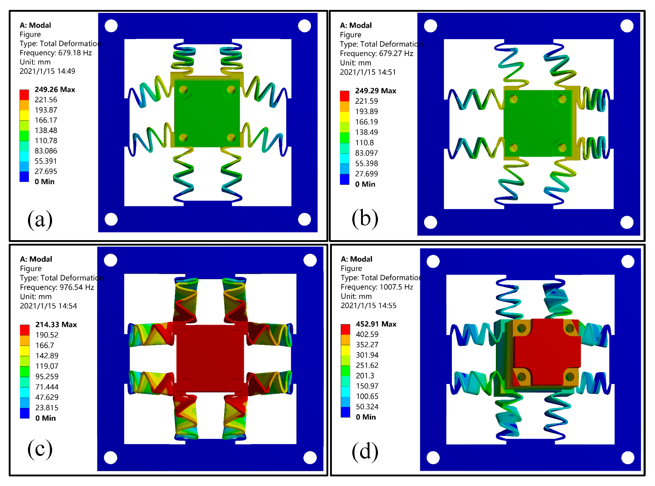
Section 5.2, FEA simulation is employed to characterize the first four resonant modes of the dual-axial flexure mechanism, which are illustrated in
Figure 7. As expected, the first two resonances have a nearly identical resonant frequency around 679 Hz, and the mode shapes are consistent with the desired dual-axial motions. Considering the structural symmetry, the analytical resonant frequencies for the first two resonant frequencies are calculated to be identical as 599.341 Hz, which deviates about 11.7% compared with the FEA result. In addition, out-of-plane translation and rotation are observed for the third and fourth mode, and the corresponding resonant frequencies are about 976.54 Hz and 1007.5 Hz, as shown in
Figure 7c,d.
Note 1 The compliance and stiffness matrices of the designed stage are presented in
Appendix A.3. From the calculated stiffness matrix
, the
z-axial stiffness (10.8 N/
m) is about two orders of magnitude larger than the
x- and
y-axial stiffness (0.408 N/
m), suggesting that the out-of-plane DOF is well-constrained.
Note 2 Compared with the in-plane rotation, the much larger tilting stiffness around the x- and y-axes suggests that the two tilting DOFs are also constrained. Although the induced rotation is relatively small (1 N disturbance on the sidewall of the platform may only lead to a slight rotation of 0.17 mrad), undesired overly large in-plane torques must be carefully avoided to eliminate in-plane rotation errors for practical applications.
6. Conclusions
A sinusoidal corrugated flexure linkage is proposed to concurrently stretch and bend, which is crucial to directly deliver dual-axial motions. Taking into full consideration this unique property, a corrugated flexure mechanism using four pairs of corrugated linkage-based parallelograms is developed for the planar nanopositioning stages to support and guide the dual-axial motions. The stiffness is analytically modeled for both the sinusoidal corrugated flexure linkage and dual-axial mechanism, and their deformation behavior related to the structural parameters are further investigated with finite element simulation-based verification. The deviation between the analytical and finite element result is less than 20% for all cases.
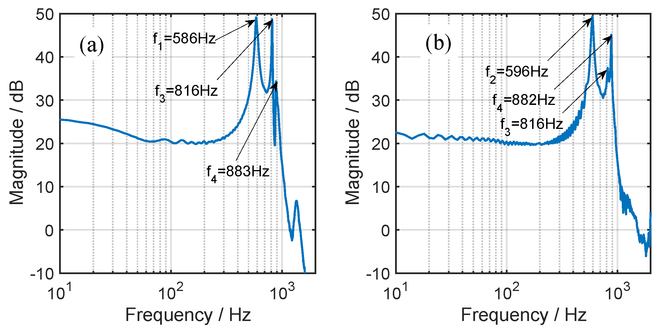
As for the dual-axial mechanism, the stiffness of the produced prototype is practically tested, and the deviation between the practical and analytical stiffness is around 7.4%. By applying the mechanism for the construction of a planar magnetic nanopositioning stage, a nearly identical stroke and resonant frequency are observed for the two axes, which are, respectively, around 130 m and 590 Hz, and the maximum cross-talk is observed to be less than 2.5%. Finally, by adopting a PID-based main controller with the disturbance observer, the closed-loop performance of the dual-axis stage is also demonstrated.


