Article

Modeling and Experimental Research of One Kind of New Planar Vortex Actuator Based on Shape Memory Alloy

1
State Key Laboratory of Mechanics and Control of Mechanical Structures, Nanjing University of Aeronautics and Astronautics, Nanjing 210016, China
2
Shanghai Institute of Satellite Engineering, China Aerospace Science and Technology Corporation, Shanghai 200109, China
3
AECC Shanghai Commercial Aircraft Engine Manufacturing Co., Ltd., Shanghai 201306, China
*
Authors to whom correspondence should be addressed.
Actuators 2022, 11(1), 8; https://doi.org/10.3390/act11010008
Submission received: 27 October 2021 / Revised: 13 December 2021 / Accepted: 23 December 2021 / Published: 31 December 2021
(This article belongs to the Special Issue Shape Memory Alloy Actuators)

Abstract

:
In order to alleviate the problems of complex structure and low reliability of traditional Shape Memory Alloy (SMA) rotary actuator, a planar vortex actuator (PVA) based on SMA material was proposed to directly output torque and angular displacement. Based on the calculation method of PVA and the constitutive model of the phase transition equation of SMA, the mechanical model is established, and the pre-tightening torque, temperature, output torque, and rotation angle are obtained. The relationship expression between the tests has verified the mechanical model. The results show that the relationship between the excitation temperature and the output torque, the coefficient of determination between the calculated value and the tested value, is 0.938, the minimum error is 0.46%, and the maximum error is 49.8%. In the relationship between angular displacement and torque, the coefficient of determination between the calculated value and the test value is 0.939, the maximum error is 58.5%, and the minimum error is 28.0%. The test results show that the calculated values of mechanical model and experimental data have similar representation form.

1. Introduction

SMA is a new kind of functional material with Shape Memory Effect (SME). SMA has excellent shape memory, superelastic properties, good mechanical properties, as well as high damping characteristics. Due to its excellent actuator characteristics, it has received widespread attention from material science and engineering circles [1,2,3,4,5]. After several decades of development, its mechanical constitutive model gradually mature. Among the constitutive models of SMA, the Brinson equation, based on phase change equation, is the most typical [6]. The Brinson model is based on Tanaka’s exponential phase transition equation [7] and the cosine phase transition equation established by Ling et al. [8]. The main feature is that the martensite volume fraction of SMA is decomposed into temperature-induced and stress-induced. The two parts overcome the limitation that other equations cannot describe: the transformation from twin martensite to non-twin martensite. On the basis of Brinson’s work, Zhou Bo et al. established the concept of shape memory factor [9,10], unified the superelasticity and shape memory phenomena of SMA material, and made the constitutive equation more concise.
SMA driver has the characteristics of being a lightweight, simple structure with simple control. In addition, the SMA driver works quietly and dust-free [11]. The application of SMA in the aerospace field is mainly in two aspects: one is to compress the antenna and other equipment into a small volume when in the launch state, as well as to restore the original shape after entering the space [12,13]. The other is to be used as the actuating element to drive the spatial mechanism [14,15,16]. In other applications, Yu Dong et al. realized the conversion of the linear deformation of the SMA into a rotary motion by the sprocket and the chain [17]. Kai Yang made a new type of embedded SMA bending drive with two SMA wires inside the elastic rod body [18]. Kotb Y et al. presented a shape memory alloy (SMA) driven micro pump optimized for drug delivery applications [19]. Barbarino et al. used SMA to drive the continuous elastic body to control the shape of the trailing edge of the wing [20]. Zhang Wei et al. designed a variable swept-back winglet structure based on SMA wire established on the changes of winglet sweep angle in different flight states [21]. Xu Lizhong et al. proposed a harmonic gear drive system with shape memory alloy. The system combines shape memory alloy drive principle with harmonic gear drive principle to achieve small size and large output torque [22].
For the SMA drive element that outputs linear displacement, the researchers made it into the form of a vortex spring to convert torsional deformation into linear displacement, increasing the linear deformation stroke [23]. For the SMA device with rotating displacement, the actuator proposed above has the disadvantages of complex motion conversion mechanism and small stroke. As a typical torsion storage and release device, scroll springs are widely used, such as brushes in micro-electromechanics, energy storage mechanisms in vacuum short-circuiters, brake buffers in jacks, etc. In the aerospace field, the unfolding action of the solar windsurfing board is powered by the flat spiral spring in the hinge [24]. The PVA proposed in this paper is pre-tightened and the torque output in the form of scroll spring is a retractable, simple structure that can directly output torque.
Conventional SMA rotary actuators must convert linear motion to rotary motion through mechanisms. Due to the addition of conversion mechanism, the driver system structure becomes complicated; weight increases and reliability decreases. In this paper, based on the traditional structure of planar vortex spring, the planar vortex actuator is designed and studied to directly output torque and angular displacement. The structure of the actuator is simplified and the reliability of the actuator is improved. In addition, compared with a planar vortex spring made of traditional metal materials, SMA planar vortex spring has the advantages of simple structure and smooth drive, and has the prospect of application in the aerospace field.
In this paper, non-contact SMA planar vortex spring is taken as an example to introduce the operating principle of this kind of device. The relationship between the output performance and the main parameters is studied, and the constitutive model is established to provide a simple calculation method for further research.

2. Mechanical Model of SMA Vortex Spring

A nitinol SMA strip with a thickness of h and a width of b is made into PVA, the radius of the vortex line is R. In the initial free state, the pitch of the spring is p and the number of turns is n.
For scroll springs of ordinary elastic materials:
ψ = T l E I
I = b h 3 12
l = 2 π n R + 4 π n p
where ψ is the strain angle, T is the torsion force, E is the elastic modulus, I is the section moment of inertia, and l is the length of deformation segment.
SMA material performance is obviously affected by stress and temperature. Therefore, when establishing the mechanical model, an appropriate constitutive model should be selected.

2.1. The Constitutive Model of SMA Material

The constitutive model of SMA used in this paper is based on the shape memory factor model proposed by Zhou Bo et al. [6], and the one-dimensional phase transition constitutive model proposed by Brinson [9,10]. The expression is:
ε = σ E ( φ ) + ε L φ s + η ( t t 0 )
where ε is the strain, σ is the stress, φ is the volume fraction of martensite, εL is the maximum recoverable strain, η is the shape memory factor, t is the temperature, and the subscript 0 is the initial state. E(φ) means that for SMA, the E is related to the φ, and its calculation method can be expressed in Equation (5):
E ( φ ) = E A ( E A E M ) φ
where EM is the modulus of elasticity of martensite, and EA is the modulus of elasticity of austenite.
Brinson gave the calculation method of the martensite volume fraction in the literature [6]. Zhou Bo gave the calculation method of the shape memory factor in the literature [9,10].
When transforming from twinned martensite to non-twinned martensite, when the temperature is lower than the initial phase transformation temperature of martensite:
η = η 0 + ( 1 η 0 ) σ σ s c r σ f c r σ s c r
φ = 1
When transforming to austenite, and the temperature is higher than the initial transformation temperature of austenite:
η = η 0 σ σ A f σ A f σ A s
φ = φ 0 2 cos π ( t A s σ / C A ) A f A s + φ 0 2
where σ is for stress, σscr is the critical stress of martensite initial transformation, σfcr is the critical stress of martensite termination transformation, σAs is the initial transformation stress of austenite, σAf is the austenite final transformation stress, and As is austenite The initial transformation temperature of austenite, Af is the termination temperature of austenite transformation, CA is the coefficient of austenite transformation temperature-critical stress.
The calculation method of the austenite initial transformation stress σAs and austenite final transformation stress σAf is:
σ A s =   C A ( t A s )             t > A s                 0                                 t A s
σ A f =   C A ( t A f )         t > A f                 0                           t A f

2.2. The Mechanical Model of PVA

The mechanical model of SMA vortex spring is established by referring to Formula (4) as follows:
Δ ψ = Δ ψ E + Δ ψ η + Δ ψ t
where Δψ is regarded as the elastic deformation caused by torsion, ΔψE and Δψη are the plastic deformation caused by the transformation of material under stress, and Δψt is the thermal expansion deformation caused by temperature change.
The following assumptions are made to the SMA vortex spring mechanics model to reduce the amount of calculation and simplify the expression.
  • Based on the assumption of one-dimensional deformation, describe the deformation process of the SMA vortex spring, and set the material to have the same elastic modulus and maximum recoverable strain during tension and compression.
  • All physical parameters of the material are the same in the deformation process.
  • The material is pure bending strain and the cross-sectional shape remains unchanged.
  • The strain caused by thermal expansion is much smaller than the elastic strain caused by torsion and the material phase change strain, so the third term in the equation is ignored.
  • The length of the deformed section of the PVA remains unchanged.
Based on the above assumptions, Equation (12) is rewritten as:
Δ ψ = Δ ψ E + Δ ψ η + Δ ψ t
In the constitutive equation proposed by Brinson, the φ is a key calculation parameter. Brinson defines it as a function of stress and temperature. Therefore, it is necessary to obtain the stress state during the deformation process when constructing the approximate mechanical model of PVA.
The deformation of the PVA is regarded as the pure bending deformation under the action of the bending moment, and the σ is the average sum of the absolute values of the stresses in the section. Assuming that the neutral layer of the structure does not change, and the stress increases linearly from the neutral layer along the thickness Y direction, then:
T   =   2 b 0 h 0 / 2 σ ( y ) y d y
σ ¯ b h = 2 b 0 h 0 / 2 σ ( y ) d y
Substituting Equation (15) into Equation (14), the average bending stress of the section is obtained as:
σ ¯ =   3 T b h 2
Substituting Equation (16) into Equations (6), (8) and (9), the martensite volume fraction of the shape memory factor under different conditions can be obtained.

3. Calculation of Driving Performance

For the PVA, the input is the pre-tightening torque and the excited temperature, and the output is the load torque and the rotation angle position.
The working process is divided into four stages: the initial state, the preloaded state, the standby state, and the excited output state.
  • Each parameter in the initial state is represented by subscript 0. Temperature is lower than martensitic initial phase transition temperature, namely t0 < Ms torque T0 = 0. The volume fraction of martensite is φ0 = 1, the memory factor is η0 = 0, the strain angle is ψ0 = 0.
  • Parameters in the pre-tightening stage are set as 1. Temperature t1 = t0 < Ms. The deformation angle of PVA under the pretightening torque T1 is ψ1:
φ 1 = φ 1 = 1
η 1 = 3 T 1 6 h 2 σ s c r σ f c r σ s c r b h 2
  ψ = T 1 l E M I + 2 ε L l η 1 h
In order to ensure that the PVA produces recoverable deformation and does not fail, the pre-tightening torque should meet the Equation (20):
1 3 b h 2 σ s c r T 1 1 3 b h 2 σ f c r
3.
The parameter in the in-use stage is set as subscript 2. Keep the temperature t2 = t0 < Ms, T2 = 0 after the preload torque is removed. After PVA recovered the elastic deformation, the residual deformation angle was ψ2:
φ 2 = φ 0 = 1
η 2 = η 1 = 3 T 1 b h 2 σ s c r σ f c r σ s c r b h 2
  ψ = 2 ε L l 3 T 1 b h 2 σ s c r σ f c r σ s c r b h 3
4.
The parameters of the excited output state are indicated by the subscript 3. When the temperature is increased to t3 > As, the PVA generates shape recovery and outputs torque and angular displacement, which are T3 and ψ3, respectively. Since the stress change is caused by the difference between the elastic modulus during the transformation from martensite to austenite, there are constraints:
T 3 1 3 b h 2 σ A s
In the recovery process, there should be no reverse transformation of austenite into martensite, so there are constraints:
T 3 1 3 b h 2 σ M s
When satisfying Equations (24) and (25), and T 3 1 3 b h 2 σ A f :
φ = φ 2 2 cos π ( t 3 A s 3 T 3 / C A b h 2 ) A f A s + φ 2 2
η 3 = η 2 = 3 T 3 / b h 2 σ A f σ A s σ A f
  ψ 3 = T 3 l E ( φ 3 ) I + 2 ε L l η 3 h
When T 3 < 1 3 b h 2 σ A f , the material phase turns into austenite:
φ 3 = 0
η 3 = 0
  ψ 3 = T 3 l E A I
The difference between the output strain angle and the strain angle to be used is regarded as the output angular displacement λ of the vortex spring element:
λ = ψ 2 ψ 3
When Equations (24) and (25) are satisfied, and when T 3 1 3 b h 2 σ A f , Equations (21)–(23) and (26)–(28) are substituted into Equation (32):
  λ = F ( T 1 ) G ( T 1 , T 3 ) 6 T 3 l b h 3 E A + ( E M E A ) H ( t 3 , T 3 ) + 1
The function in Formula (33) has the following meanings:
F 1 = 6 ε L T 1 l 2 ε L b h 2 σ s c r σ f c r σ s c r b h 3
G ( T 1 , T 3 ) = 2 ε L / ( 3 T 1 b h 2 σ s c r ) ( 3 T 3 b h 2 σ A f ) σ f c r σ s c r σ A s σ A f b 2 h 5
H ( t 3 T 3 ) = c o s π A f A s ( t 3 A s 3 T 3 C A b h 2 )
When T 3 < 1 3 b h 2 σ A f , substitute Equations (21)–(23) and (26)–(28) into Equation (32):
  λ = ε L l 3 T 1 b h 2 σ s c r σ f c r σ s c r b h 3 12 T 3 l E A b h 2
Equations (33) and (34) are the relation expressions of λ with T3, t3 and T1.
Defects are common in engineering models [25]. The model can only describe the basic characteristics of PVA driving elements before and after phase transformation due to many assumptions made to simplify the expression.

4. Validations and Discussions

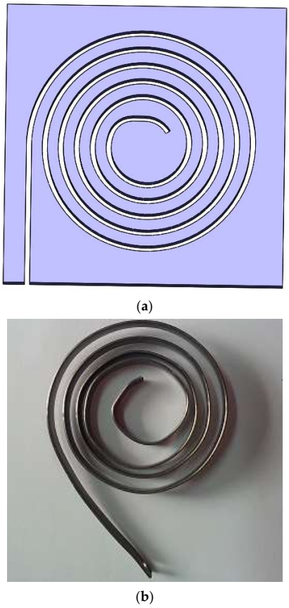
4.1. Design and Manufacture of PVA Sample

The PVA is divided into working section and installation section. The projection of the effective working section is Archimedes spiral, and the expression can be expressed as Equation (35):
r = r 1 + θ 2 π t r θ [ 0 , 2 π n ]
where r1 is the polar diameter of the starting point of the spiral, r is the polar diameter of any point of the spiral, θ is the polar angle of any point, tr is the pitch of the spiral, and n is the winding number. The length of the working section can be calculated according to Equation (35):
l = 0 2 π n r d θ = 2 π r 1 n + π t r N 2
Table 1 is the geometric parameters of PVA.
As shown in Figure 1, the mold is wire cut steel plate. In order to facilitate material embedding and demolding after heat treatment, the width of groove is 0.3 mm~0.5 mm more than the thickness of the strip. The strip was embedded into the shaping mold to obtain PVA sample.

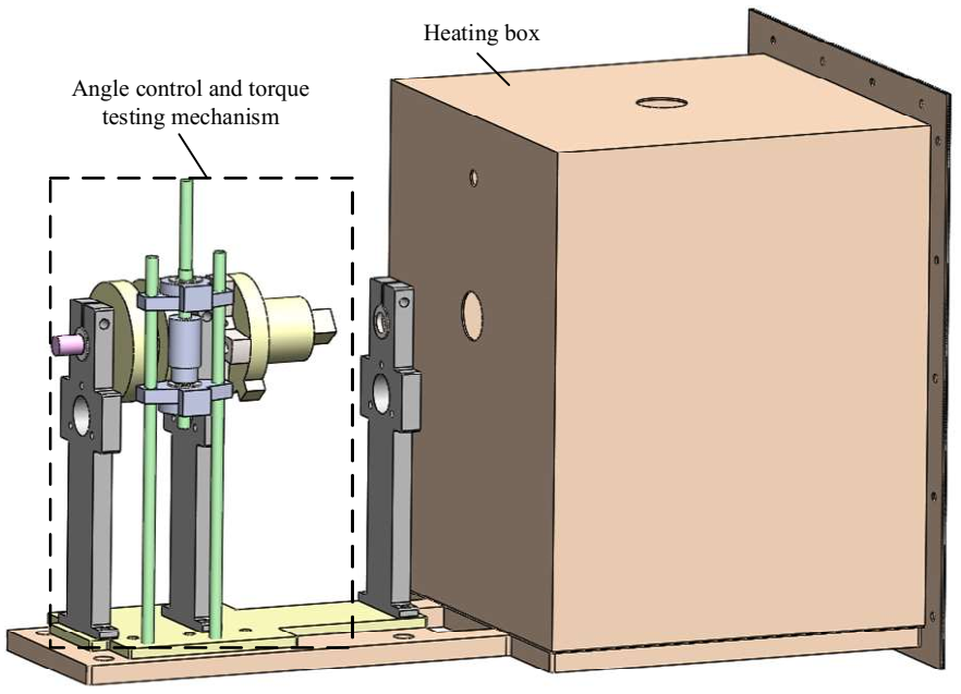
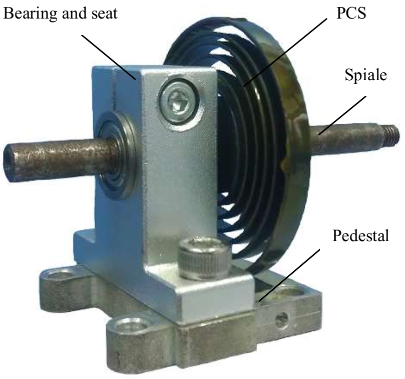
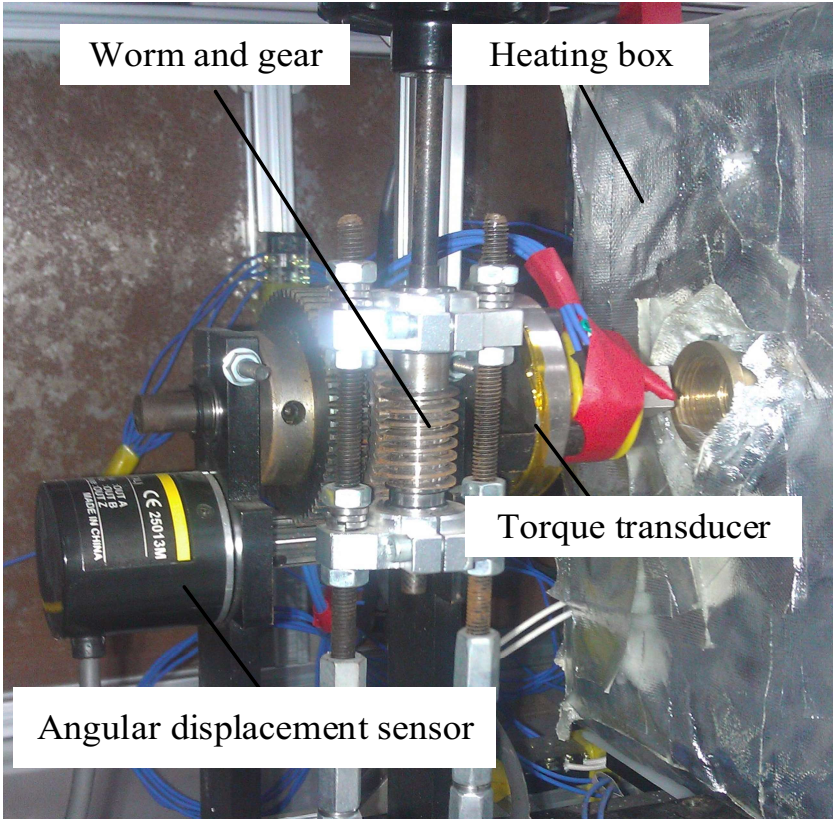
4.2. Test System Design and Construction

As shown in Figure 2, the test system includes angle control, torque testing device, and heating box. As shown in Figure 3, PVA includes a rotating shaft, bearing support and mounting base. The test system is shown in Figure 4. Utilizing the self-locking characteristics of worm gear, the system can control the angular deformation at any position. Using the WAN-5 torque sensor to record the output torque. E6B2 encoder was used as an angular displacement sensor to record angular deformation. The temperature was controlled by heating box.
Nitinol alloy was selected as the preparation material of PVA, and the performance parameters and geometric structure parameters of the material are shown in Table 2 and Table 3.

4.3. Experimental Validations

In order to study the relationship between the angular displacement and the excitation temperature, the angular displacement of PVA was tested under different excitation temperatures. The initial martensite state of PVA can be obtained by twin martensite loading or austenite cooling. The above two different acquisition methods were studied experimentally. The torques were set as 25 × 10−3 N·m, 50 × 10−3 N·m and 75 × 10−3 N·m, respectively. The test results are shown in Figure 5. Curve A indicates that the initial state of martensite is obtained after loading twin martensite, and curve B indicates that the initial state of martensite is obtained by lowering the temperature from austenite state.
In Figure 5a, the angular displacement of curve A decreases from 142° to 49°, and that of curve B decreases from 147° to 51°. The significant change stage of angular displacement is from 47 °C to 64 °C. In Figure 5b, the angular displacement of curve A decreases from 245° to 93°, and that of curve B decreases from 275° to 91°. The significant change stage of angular displacement is from 48 °C to 69 °C. In Figure 5c, the angular displacement of curve A decreases from 433° to 150°, and that of curve B decreases from 469° to 152°. The significant change stage of angular displacement is from 46 °C to 75 °C.
The temperature range where the angular deformation changed significantly was the transformation process of PVA from martensite to austenite. Under different torques, the phase transition temperature sections of curves A and B are basically the same, which proves that the way of obtaining the initial state of martensite has trivial influence on the phase transition process. After the heating process is completed, the amount of PVA angular deformation is only related to the loading torque since the material is completely reversed phase into austenite.
By comparing the initial states of curves A and B, it can be found that the values of the two are almost identical in Figure 5a, which indicates that the initial states of the two martensite are almost the same under the condition that PVA does not produce non-twin martensite under the action of low load. However, in Figure 5b,c, the initial value of curve B is greater than that of curve A, indicating that more non-twin martensite can be generated in the material from the state reached by cooling from austenite under constant load compared with loading from twin martensite to set load.
The excitation temperature is expressed in ten, the pre-tightening torque is expressed in Tpre, and the output torque is expressed in Tex. The process of the experiment is as follows:
  • Heat the PVA to 80 °C (above Af) in a free state, and slowly decrease the temperature to 20 °C (below Mf). Repeat more than three times to make sure the material is in full twin martensite state.
  • Set the ambient temperature to 20 °C (lower than As), and preload the PVA to 270° according to the constraints of Equation (20), and the Tpre is 0.069 N·m. After the restraint is released, the residual strain is 214°. Connect the test device to the test system.
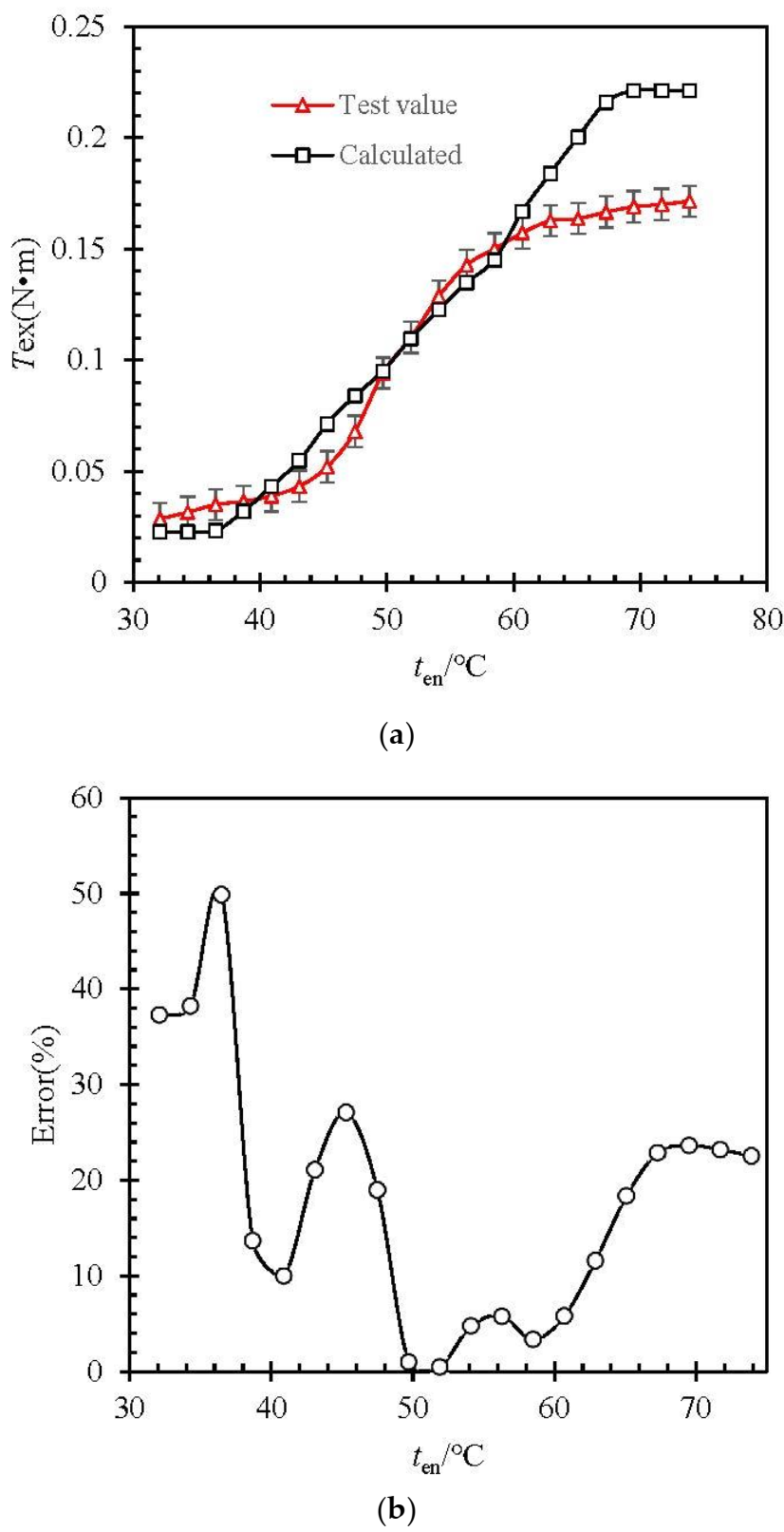
  • The initial temperature of the water bath was set at 30 °C (lower than As), and the temperature is raised at 2 °C/min. The values of ten and Tex of the water bath are recorded. The values recorded in the test are compared with those calculated by Equations (33) and (34), and the results are shown in Figure 6.
4.
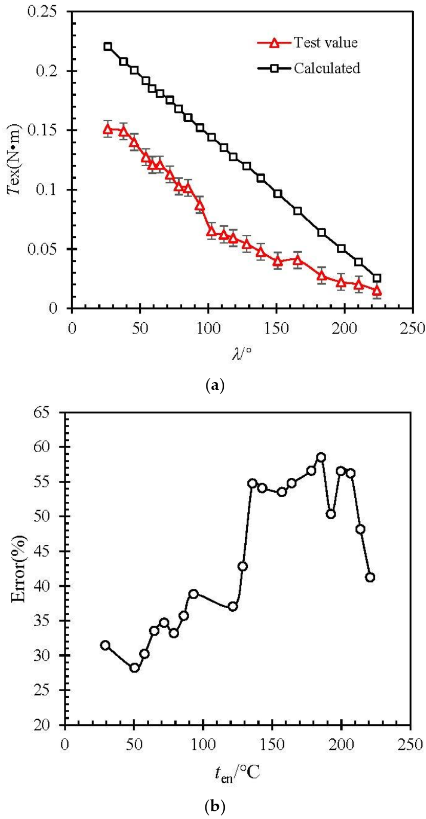
When the torque output value Tex is stable, keep the excitation temperature ten unchanged (70 °C). Through the limit device, the angular displacement of the SMA vortex spring is increased by 3 (°)/s, and the value of the angular displacement λ and the torque output Tex are recorded. Compare the value of the test record with the value calculated according to Equations (33) and (34). The result is shown in Figure 7.

4.4. Error Discussions

In the pre-tightening stage, the elastic deformation is less than the calculated amount, about 122°, but the residual strain error is small, about 10°. The error rate curve between the calculated value of excitation temperature and output torque and the test value is shown in Figure 6. The calculation of the error is as follows:
e = ( α β ) α × 100 %
where e is the error rate, and α is the test value, and β is the calculated value. The maximum error rate is 49.8%, at 37 °C and the minimum error rate is 0.46% at 52 °C. On the whole, the determination coefficient R-square of the theoretical calculation value to the test value is 0.938.
The error rate curves of calculated and tested values of angular displacement and torsion are shown in Figure 7. The maximum error rate is 58.5% at 151°, and the minimum error rate is 28% at 37°. The R-square of the theoretical calculation value to the test value is 0.939. Since the material has transformed into full austenite and the elastic modulus is constant EA, the angular displacement and torque output should be linear. In Figure 7a, the slope of the calculated value of the model is −9.9 × 10⁻⁴ N·m/(°). The slope of the fitting straight line of the test data points is −7.7 × 10⁻⁴ N·m/(°).
The main reasons for the error between the calculated value and the test value of the model are as follows:
(1) The basic mechanical model of vortex springs in the standard uses the assumption of multi-vortex springs. There will be some error when calculating the vortex spring with a less winding number.
(2) The existing constitutive models of SMA materials have errors compared with the actual situation.
(3) The mechanical model uses the assumption that the deformation mode of all materials is pure bending and small deformation, while ignoring the thermal expansion caused by temperature change. These assumptions can simplify the calculation process, but they are different from the actual situation.
In view of the above causes of errors, the following points can be used as improvements to reduce errors:
  • More experiments were conducted to increase the correction coefficient of the effect of spring vortex number on the mechanical model.
  • The deformation model of large deformation and non-pure bending is established.
  • It is no longer assumed that the stress and strain of each part of the strip are the same, but the distribution law of stress and strain is emphatically discussed.
  • The influence of thermal expansion caused by temperature on the mechanical model is considered, especially when the number of vortex springs is large and the material length is long.
  • The one-dimensional constitutive equation in the mechanical model is replaced by three-dimensional constitutive equation.
  • The finite element method is used as the numerical calculation method to provide a verification means for the establishment of the theoretical model.

5. Conclusions

In this paper, the SMA strip was prepared in the form of vortex spring, which was excited by temperature after pre-tightening, without the need of motion conversion mechanism, and directly output torque. The maximum torque in this paper exceeds 0.16 N·m and the maximum angular displacement exceeds 200°. A mechanical model of PVA is established based on the calculation method of ordinary vortex springs in the standard and the SMA phase change constitutive model proposed by Brinson and Zhou Bo. The mechanical model is verified by testing. The error analysis of calculation and test shows that the maximum error rate between excitation temperature and output torque is 49.8%. The maximum error rate between the angular displacement and the output torque is 58.5%. The main reason is that the mechanical model uses the assumption of springs with many turns, and errors will be generated for springs with fewer turns. Secondly, the influence of thermal expansion on the model has not been considered. In the further study, the coil number of spring and thermal expansion factor on the mechanical model should be considered. At the same time, finite element numerical calculation is added as a means to verify the theoretical model.

Author Contributions

Writing—original draft: X.K.; Writing—review and editing: Y.G.; formal analysis: J.W.; validation: Y.Y.; supervision: X.S.; All authors have read and agreed to the published version of the manuscript.

Funding

This study was supported by the National Natural Science Foundation of China (No. 11872207), Foundation of State Key Laboratory of Mechanics and Control of Mechanical Structures (No. MCMS-I-0520G01), Aeronautical Science Foundation of China (No. 20180952007) and Foundation of National Key Laboratory on Ship Vibration and Noise (No. 614220400307). The National Key Research and Development Program of China (NO.2019YFA708904).

Institutional Review Board Statement

Not applicable.

Informed Consent Statement

Not applicable.

Data Availability Statement

Data can be available from [email protected].

Conflicts of Interest

The authors declare no conflict of interest.

References

  1. Lambert, T.R.; Gurley, A.; Beale, D. SMA actuator material model with self-sensing and sliding-mode control; experiment and multibody dynamics model. Smart Mater. Struct. 2017, 26, 035004. [Google Scholar] [CrossRef]
  2. Park, S.; Hwang, D. An experimental study on precision positioning characteristics of shape memory alloy actuator. Microsyst. Technol. 2020, 26, 2801–2807. [Google Scholar] [CrossRef]
  3. Nizamani, A.M.; Daudpoto, J.; Nizamani, M.A. Development of faster SMA actuators. Shape Mem. Alloys Fundam. Appl. 2017, 105–126. [Google Scholar] [CrossRef] [Green Version]
  4. Mehrabi, H.; Aminzahed, I. Design and testing of a microgripper with SMA actuator for manipulation of micro components. Microsyst. Technol. 2020, 26, 531–536. [Google Scholar] [CrossRef]
  5. Khan, A.M.; Mansour, N.A.; Kim, Y.; Shin, B.; Ryu, B. Modeling of Novel Arc Shaped SMA Actuator. In Information Storage and Processing Systems; American Society of Mechanical Engineers: New York, NY, USA, 2021; Volume 84799, p. V001T09A004. [Google Scholar]
  6. Brinson, L. One-Dimensional Constitutive Behavior of Shape Memory Alloys: Thermomechanical Derivation with Non-Constant Material Functions and Redefined Martensite Internal Variable. J. Intell. Mater. Syst. Struct. 1993, 4, 229–242. [Google Scholar] [CrossRef]
  7. Tanaka, K. A thermomechanical sketch of shape memory effect: One-dimensional tensile behavior. Res. Mech. 1986, 18, 251–263. [Google Scholar]
  8. Liang, C.; Rogers, C.A. One-Dimensional Thermomechanical Constitutive Relations for Shape Memory Materials. J. Intell. Mater. Syst. Struct. 2013, 1, 207–234. [Google Scholar] [CrossRef]
  9. Zhou, B.; Wang, Z.Q.; Liang, W.Y. A micromechanical constitutive model of shape memory alloys. Acta Metall. Sin. 2006, 42, 919–924. (In Chinese). [Google Scholar]
  10. Zhou, B.; Liu, Y.J.; Leng, J.S. A macro-mechanical constitutive model of shape memory alloys. China Ser. G 2009, 7, 998–1006. [Google Scholar] [CrossRef]
  11. Wang, W.; Liu, Y. Structure Design and Research of Dexterous Finger based on the SMA Driver. In IOP Conference Series: Materials Science and Engineering; IOP Publication: Bristol, UK, 2018; Volume 439, p. 032078. [Google Scholar]
  12. Zhang, Q.; Tang, B.; Cai, J.; Yang, R.; Feng, J. Development and experimental verification of an adaptive structure for phased antenna array using SMA bunch. Eng. Struct. 2020, 225, 111293. [Google Scholar] [CrossRef]
  13. Kalra, S.; Bhattacharya, B.; Munjal, B.S. Design of shape memory alloy actuated intelligent parabolic antenna for space applications. Smart Mater. Struct. 2017, 26, 095015. [Google Scholar] [CrossRef]
  14. Pan, X.; Zhang, Y.; Lu, Y.; Yang, F.; Yue, H. A reusable SMA actuated non-explosive lock-release mechanism for space application. Int. J. Smart Nano Mater. 2020, 11, 65–77. [Google Scholar] [CrossRef]
  15. Wang, Y. Future Prospects of Space Robots. In Space Robotics; Springer: Singapore, 2021; pp. 353–363. [Google Scholar]
  16. Bian, K.; Zhou, C.; Zhao, F.; Wu, Y.; Xiong, K. Investigation of a shape memory alloy releasable mechanism applied in space environment. Int. J. Appl. Electromagn. Mech. 2020, 64, 393–401. [Google Scholar] [CrossRef]
  17. Yu, D.; Zhang, B.M.; Jinl, X. Structural Design Method of Rotation Gear Actuated by Shape Memory Alloys. J. Mech. Eng. 2010, 14, 91–94. (In Chinese). [Google Scholar] [CrossRef]
  18. Yang, K. Research and Application of New Inserted Shape Memory Alloy Actuators. IEEE Trans. Ind. Electron. 2010, 57, 2845–2850. [Google Scholar] [CrossRef]
  19. Kotb, Y.; Elgamal, I.; Serry, M. Shape Memory Alloy Capsule Micropump for Drug Delivery Applications. Micromachines 2021, 12, 520. [Google Scholar] [CrossRef] [PubMed]
  20. Barbarino, S.; Ameduri, S.; Pecora, R. Wing chamber control architectures based on SMA: Numerical investigations. In International Conference on Smart Materials and Nanotechnology in Engineering; International Society for Optics and Photonics: San Diego, CA, USA, 2007; Volume 6423, p. 64231E. [Google Scholar]
  21. Zhang, W.; Zhang, C.; Liu, B.; Zhang, B.; Wang, L. Research on Variable Sweepback Angle of Winglet Driven by Shape Memory Alloy. In IOP Conference Series: Materials Science and Engineering; IOP Publication: Bristol, UK, 2020; Volume 926, p. 012014. [Google Scholar]
  22. Xu, L.; Fu, Z. Multifield coupled analysis for a harmonic movable tooth drive system integrated with shape memory alloys. Appl. Math. Model. 2019, 69, 493–505. [Google Scholar] [CrossRef]
  23. Borboni, A.; Aggogeri, F.; Pellegrini, N.; Faglia, R. Innovative modular SMA actuator. In Advanced Materials Research; Trans. Tech. Publications Ltd.: Zurich, Switzerland, 2012; Volume 590, pp. 405–410. [Google Scholar]
  24. Sun, J. Parameters design of spiral spring in solar panel. Spacecr. Eng. 2000, 9, 37–43. (In Chinese). [Google Scholar]
  25. Bucolo, M.; Buscarino, A.; Famoso, C. Control of imperfect dynamical systems. Nonlinear Dyn. 2019, 98, 2989–2999. [Google Scholar] [CrossRef]
Figure 1. Mold and sample of PVA. (a) Mold and (b) sample.
Actuators 11 00008 g001
Figure 2. The design of test system.
Actuators 11 00008 g002
Figure 3. PVA test device.
Actuators 11 00008 g003
Figure 4. Physical test system.
Actuators 11 00008 g004
Figure 5. Relationship between temperature and angular deformation under different torques. (a) 25 × 10−3 N·m; (b) 50 × 10−3 N·m; (c) 75 × 10−3 N·m; (Curve A represents martensite after loading twin martensite, and curve B represents martensite after austenite state is lowered temperature.)
Actuators 11 00008 g005aActuators 11 00008 g005b
Figure 6. Relationship between torque and excitation temperature. (a) Test value and calculated, (b) error between test value and calculated.
Actuators 11 00008 g006
Figure 7. Relationship between torsion force and angular displacement. (a) Test value and calculated; (b) error between test value and calculated.
Actuators 11 00008 g007
Table 1. Geometric parameters of PVA.
r1 (mm)Ntr (mm)l (mm)h/(mm)b (mm)
64.53.53900.84.5
Table 2. Material parameters of PVA.
Ms/°CMf/°CAs/°CAf/°CEM/GPaEA/GPa
2722.535552250
CM/MPa·(°C)−1CA/MPa·(°C)−1 σ s c r /MPa σ f c r /MPa ε L /%
817351505.5
Table 3. Structural parameters of PVA.
b/mmh/mmRs/mmp/mmn0
6.50.83353.5
Publisher’s Note: MDPI stays neutral with regard to jurisdictional claims in published maps and institutional affiliations.

