
Design and Analysis of a Novel Composited Electromagnetic Linear Actuator


Abstract
:1. Introduction
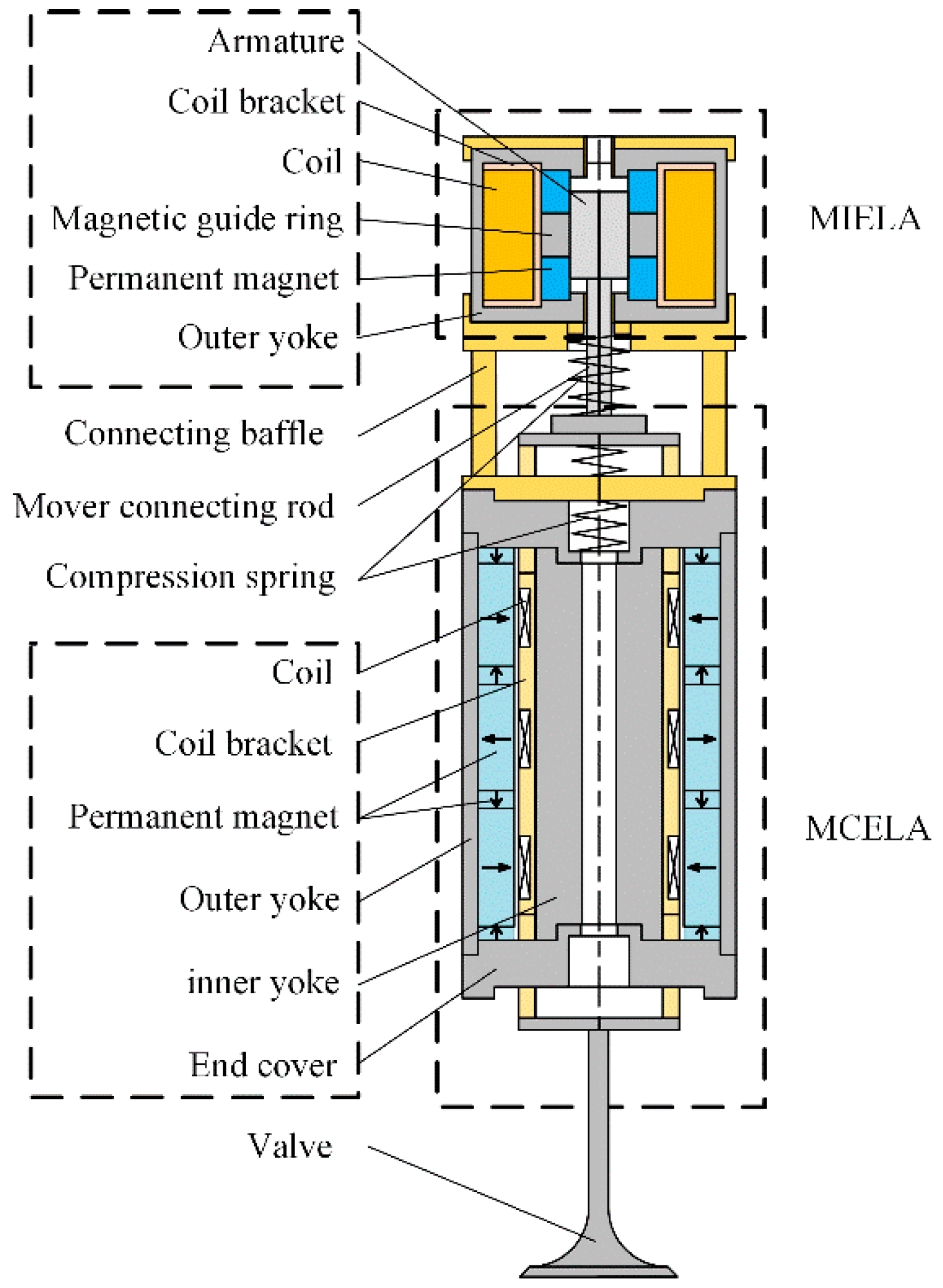
2. System Structure Design
- (1)
- High efficiency and energy-saving capacity: the actuator has a large driving force to meet the needs of various occasions, and it also has end-passive self-holding capacity and saves the electric energy that is needed to overcome the gas pressure at the end of the stroke.
- (2)
- High precision: through the integrated design and collaborative control of MCELA and MIELA, the control accuracy of CELA is improved.
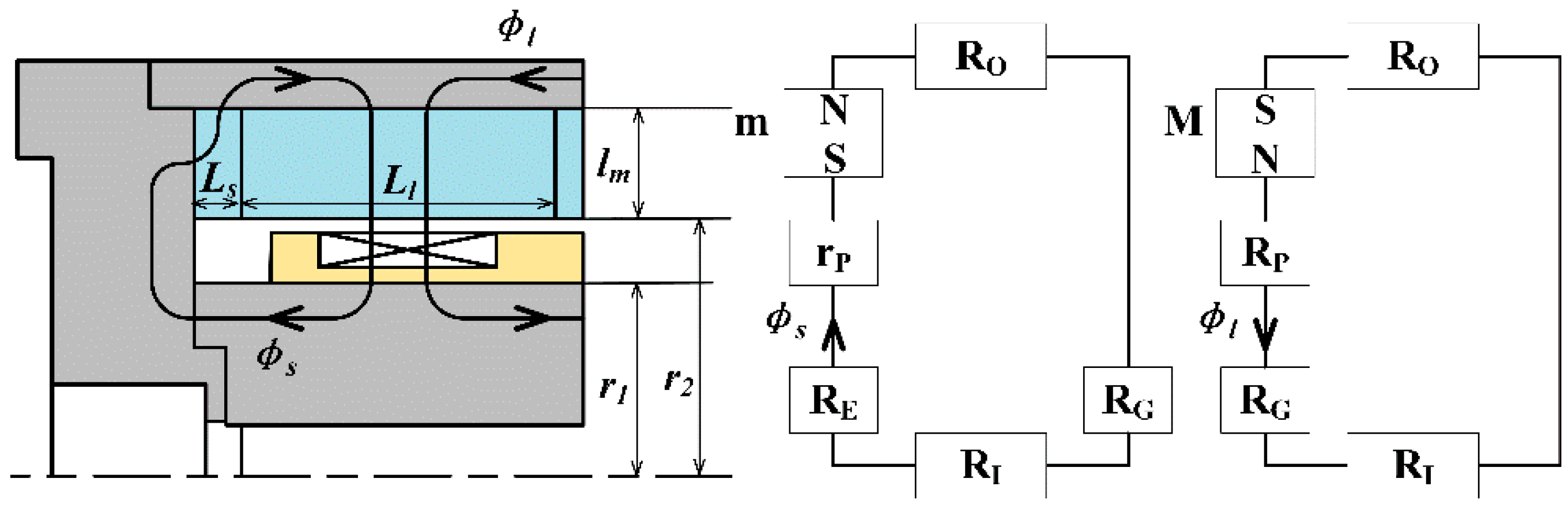
2.1. The MCELA
2.2. The MIELA
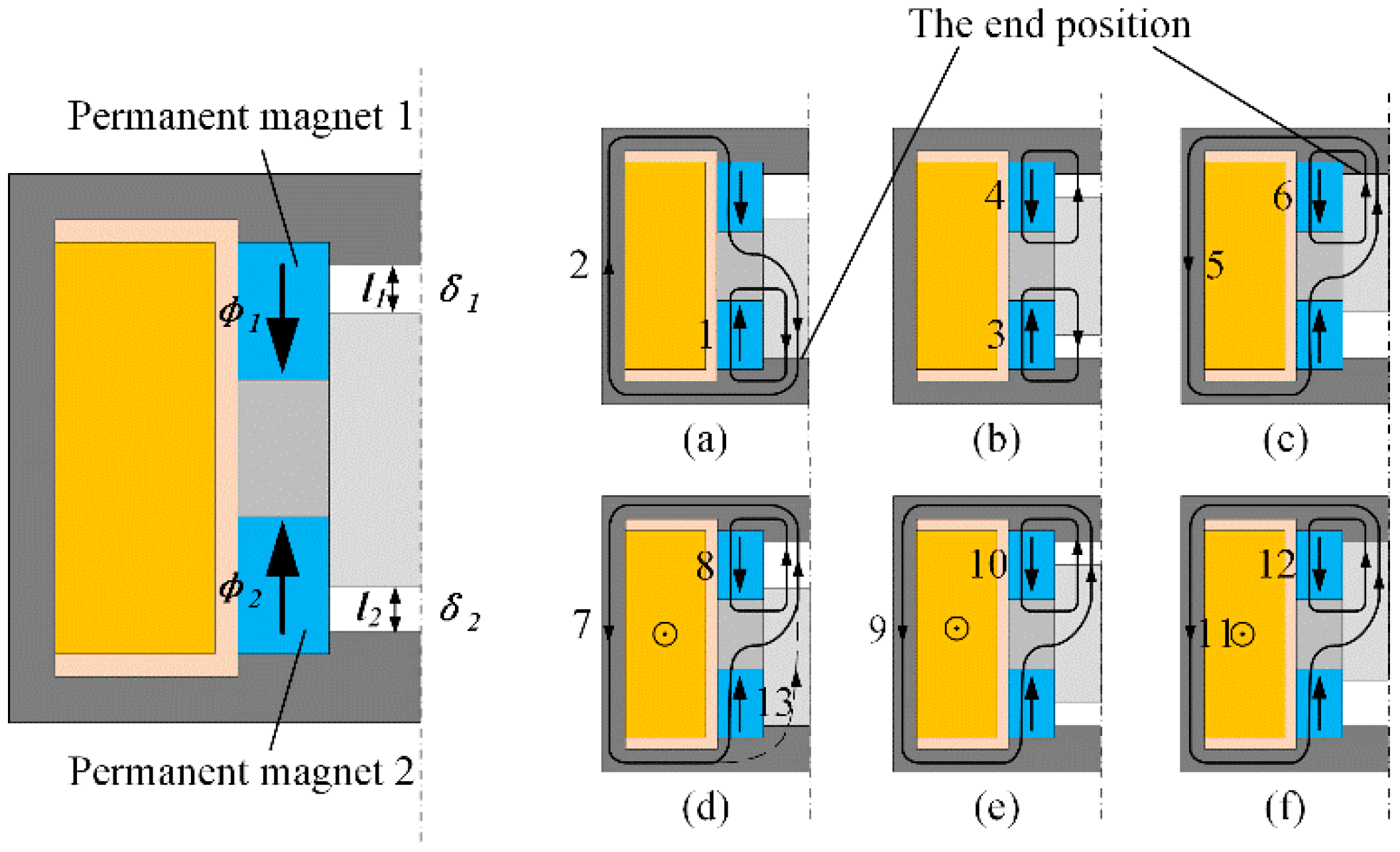
2.2.1. In the Passive State, the Magnetic Flux of MIELA Is Composed of Permanent Magnets
- Lower-end steady state (Figure 3a):
- Middle steady state (Figure 3b):
- Upper-end steady state (Figure 3c):
2.2.2. In the Active State, the Magnetic Flux of MIELA Is Composed of Permanent Magnet and Energized Coil
3. Three-Dimensional Finite Element Simulation
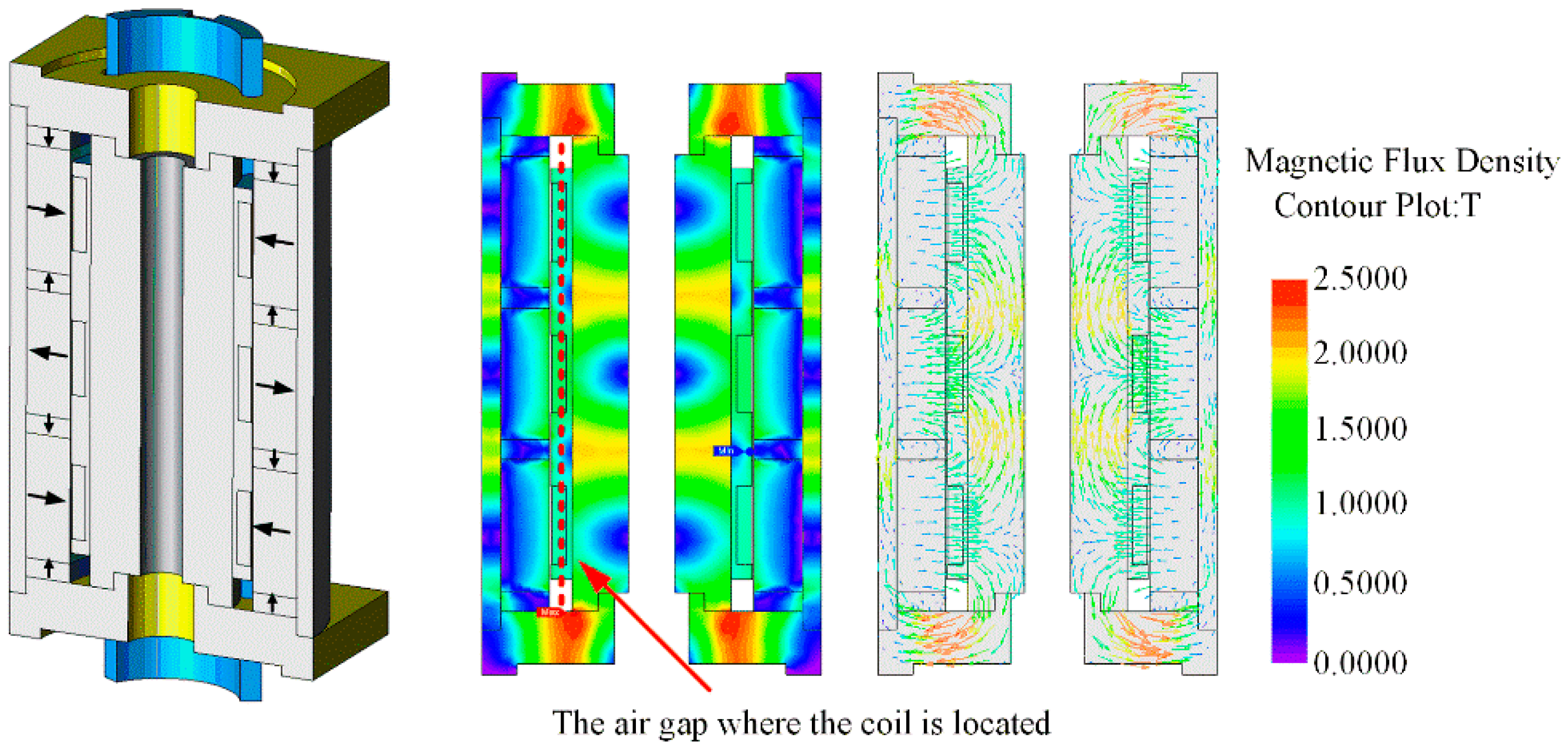
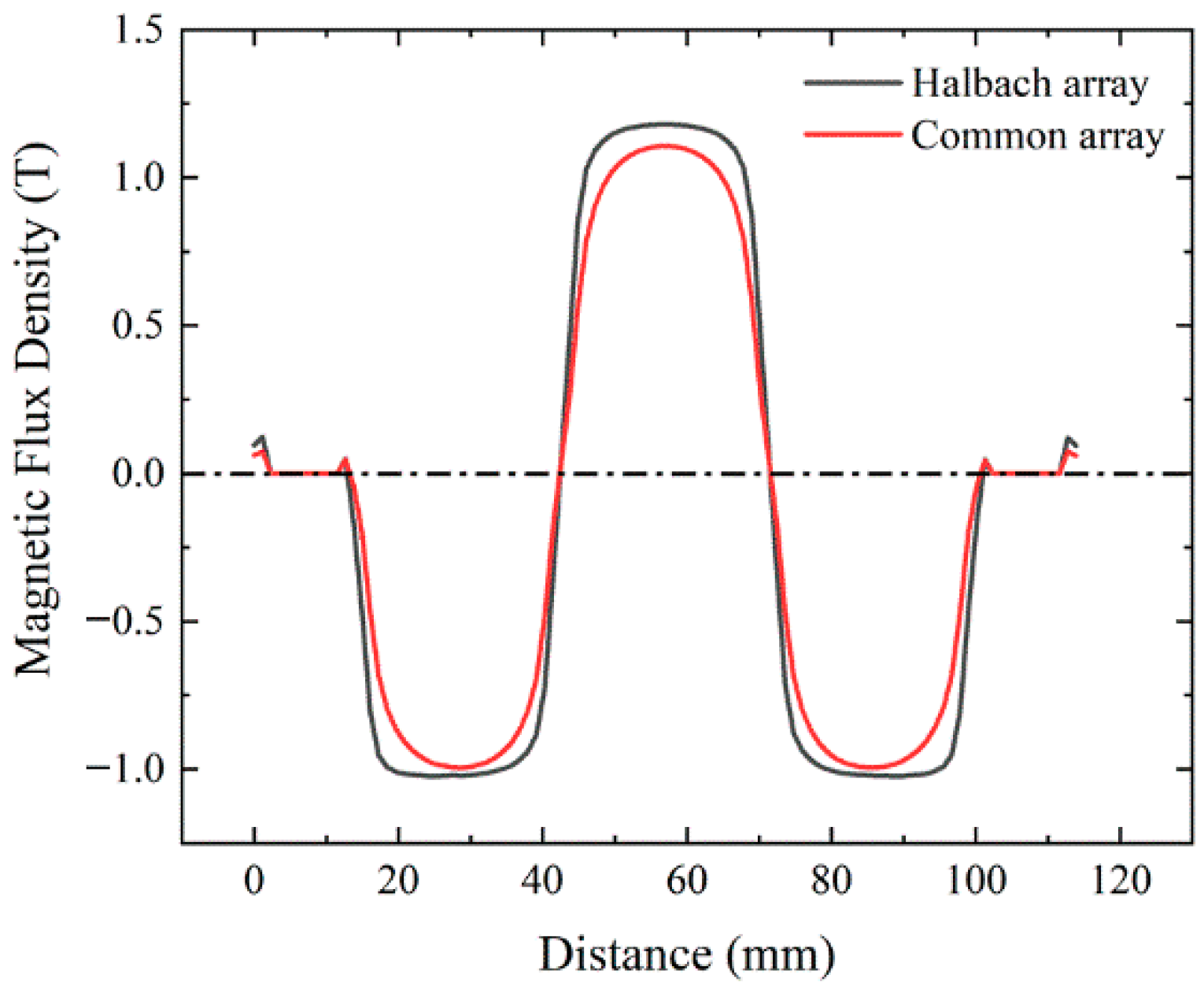
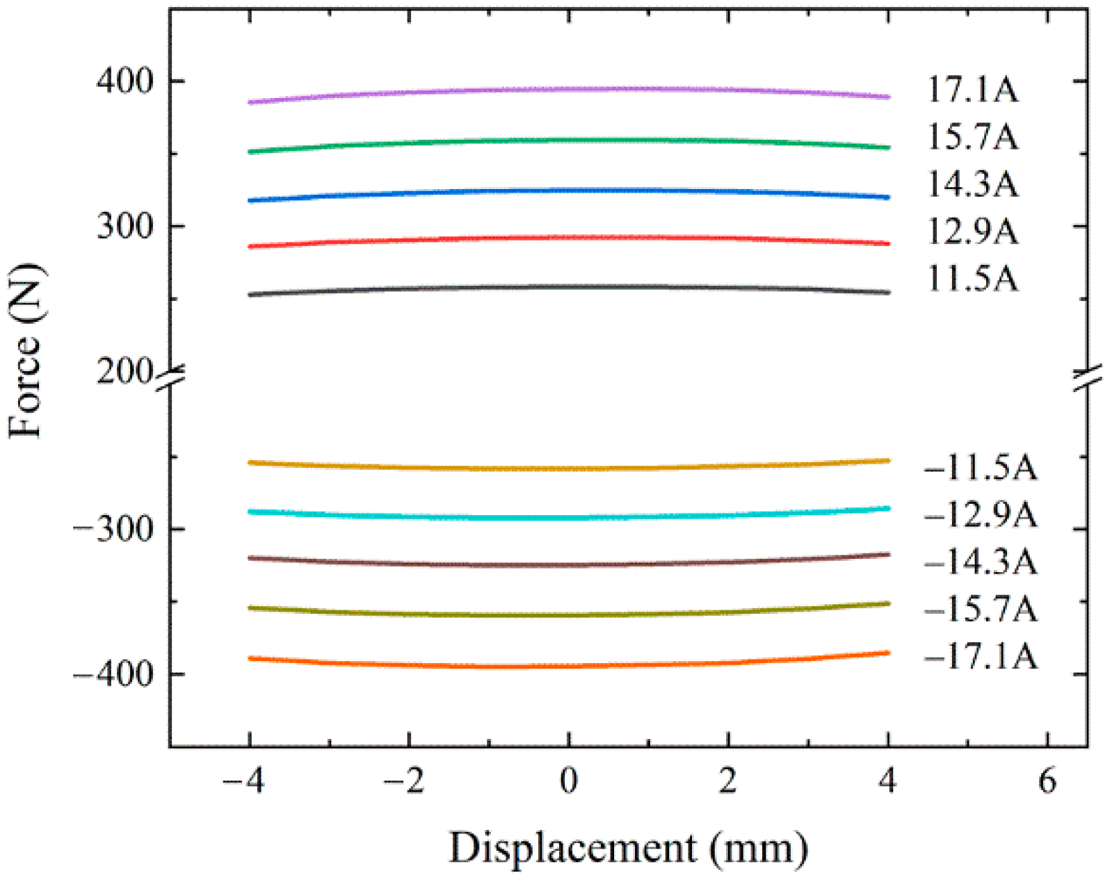
3.1. MCELA
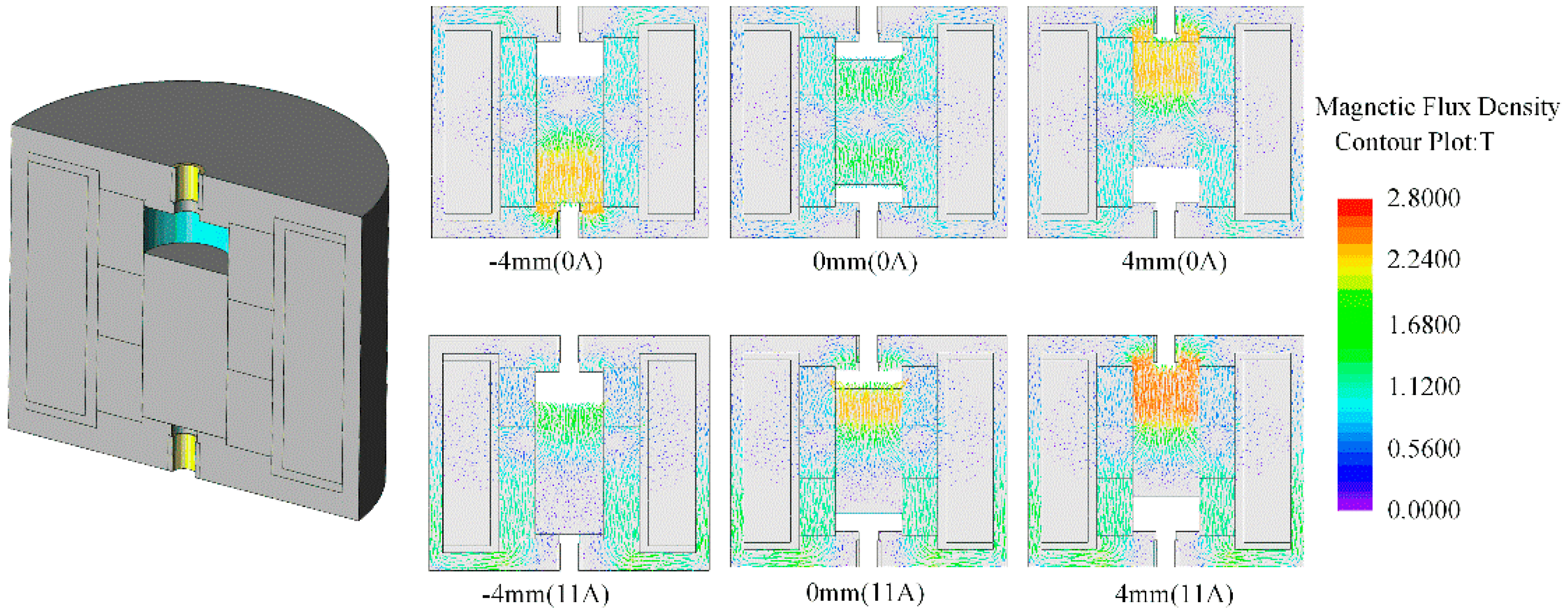
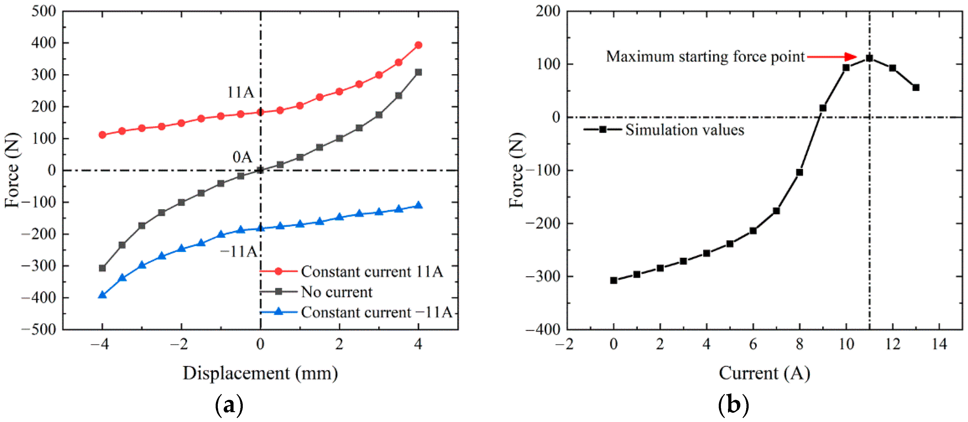
3.2. MIELA
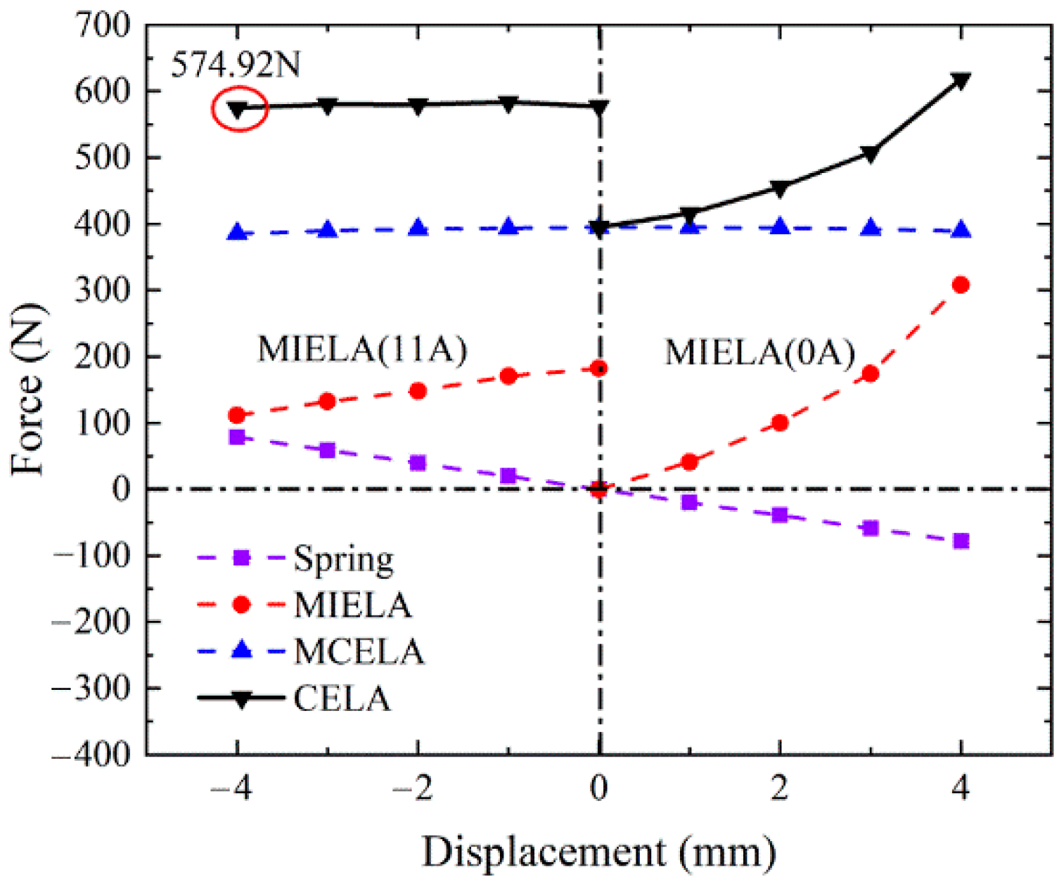
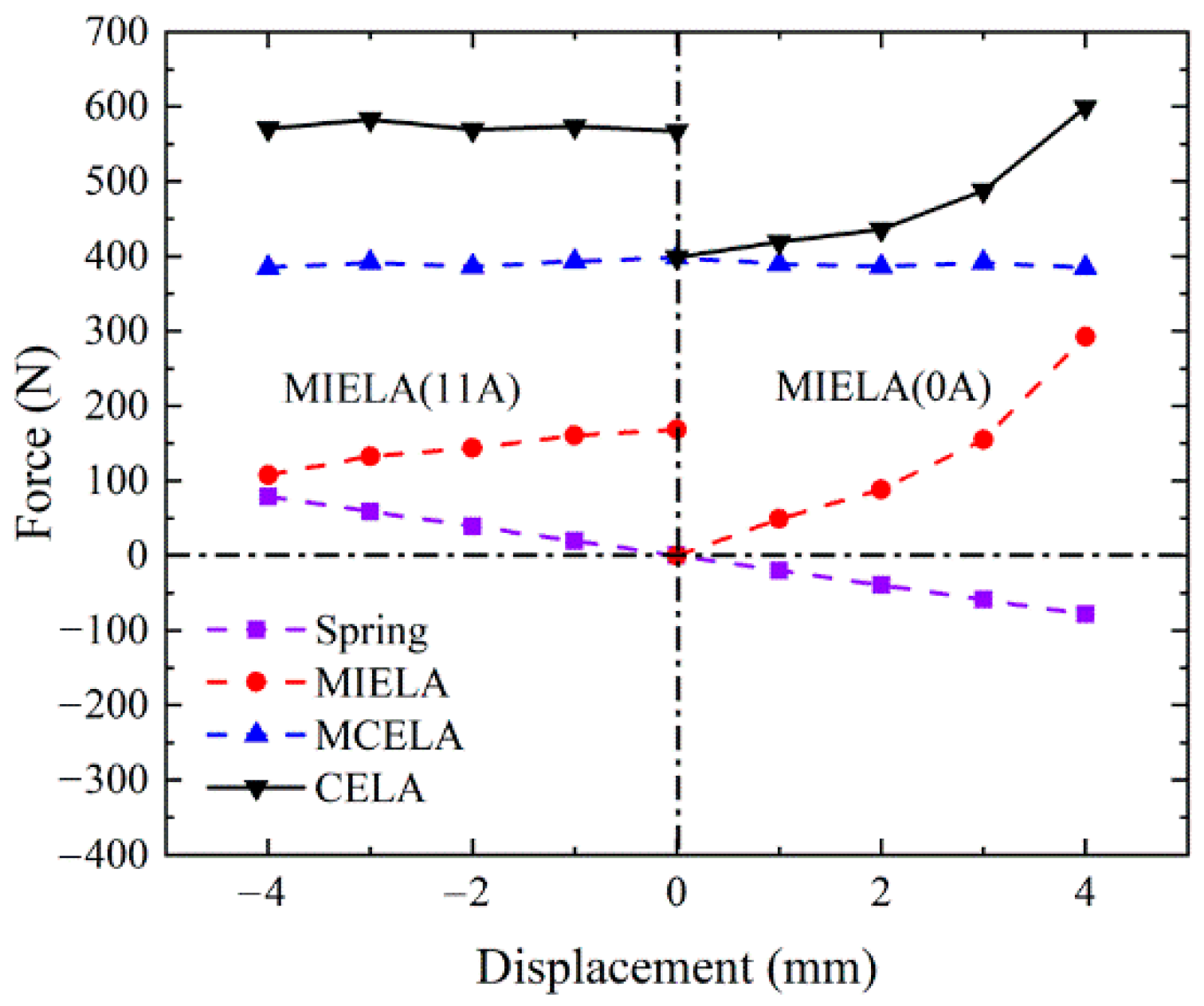
3.3. CELA
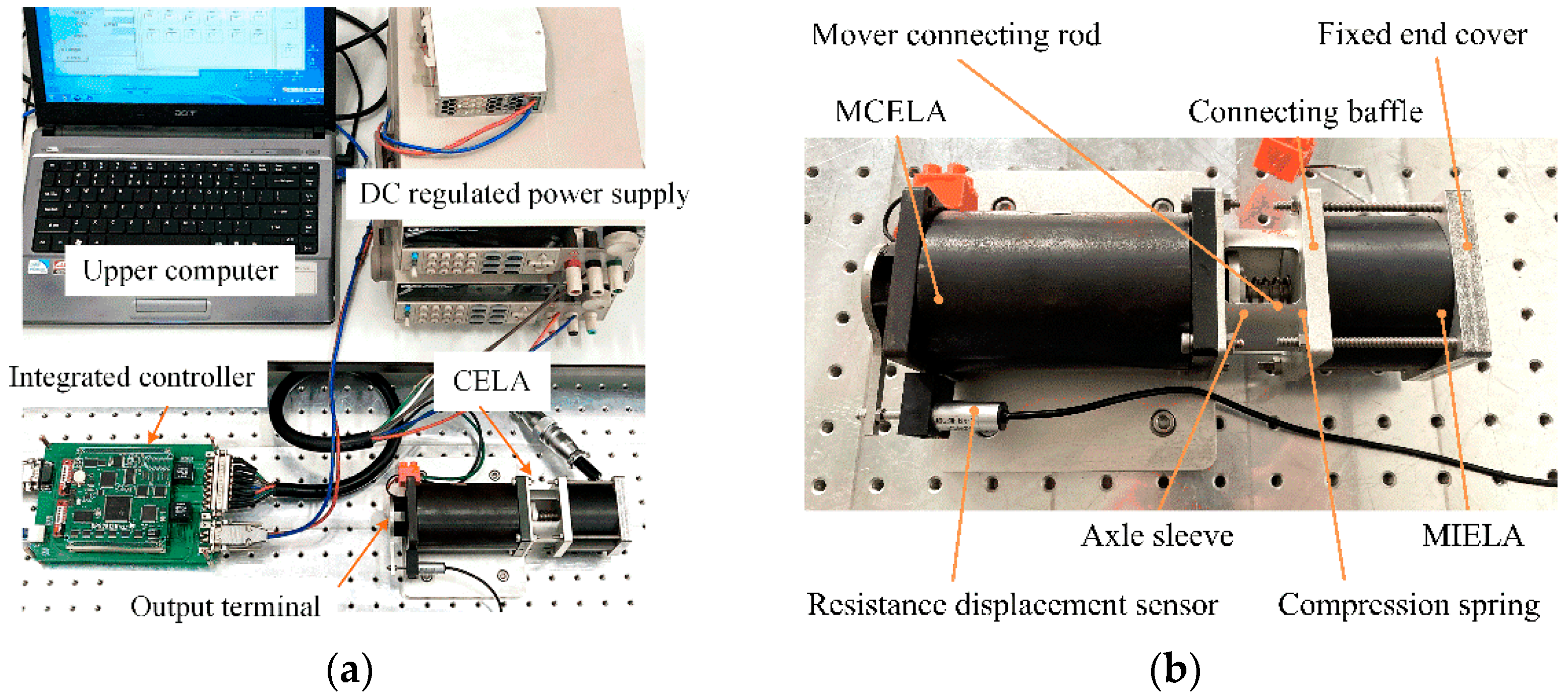
4. Verification of Experimental Results
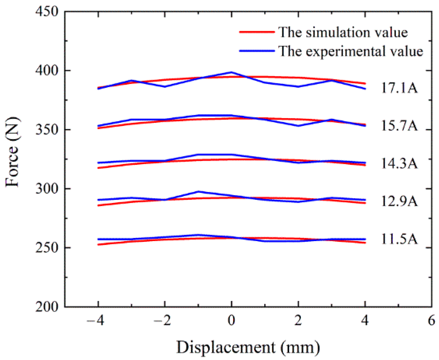
4.1. The Steady State Experiment
4.2. The Dynamic Experiment
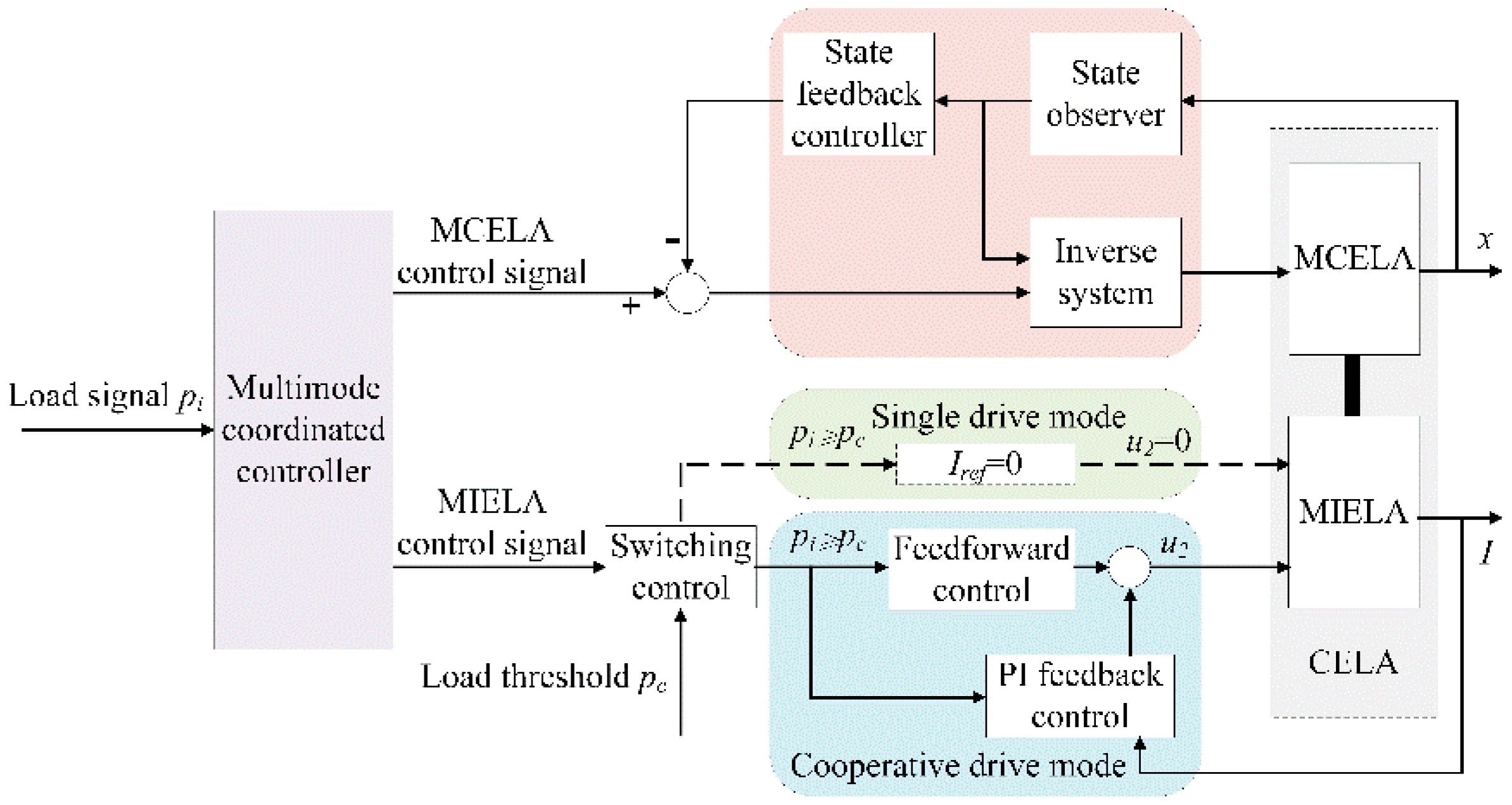
- The cooperative drive mode is adopted when the load force is large and both actuator coils are energized to generate high driving force to overcome the load;
- When the load force is small, the coil of MCELA is energized separately, and MIELA moves with it to reduce the energy consumption of the system.
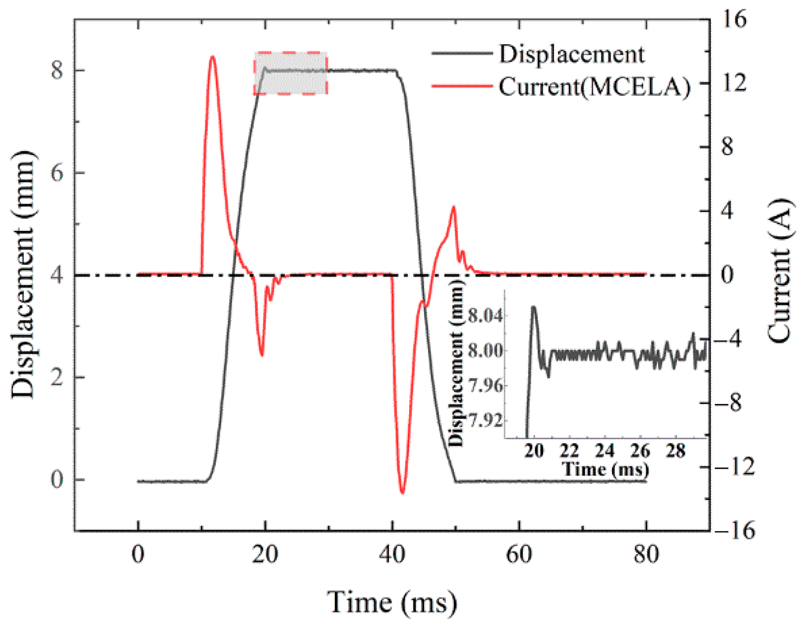
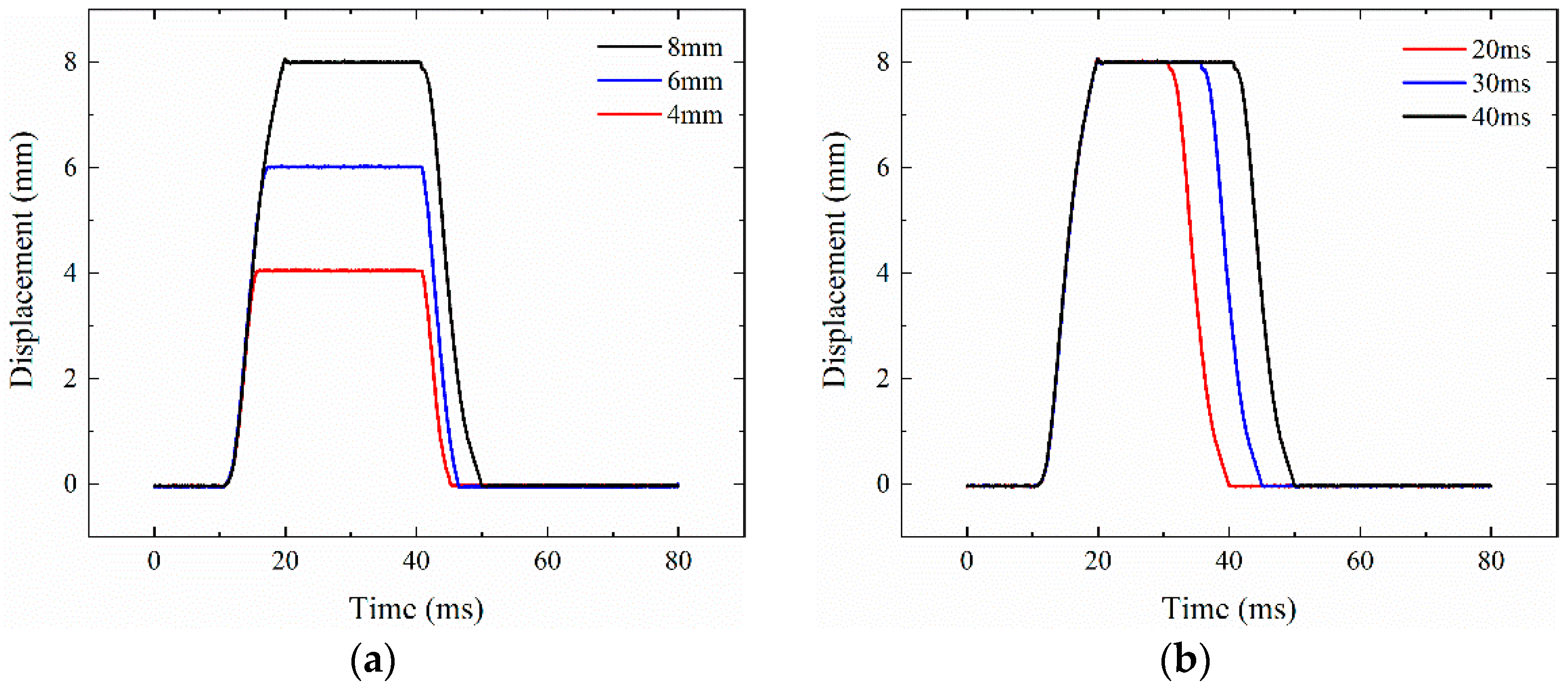
4.2.1. Single Drive Mode
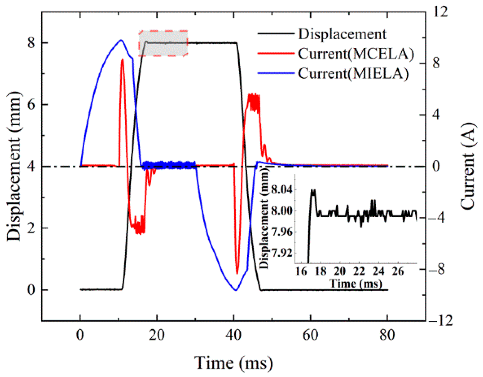
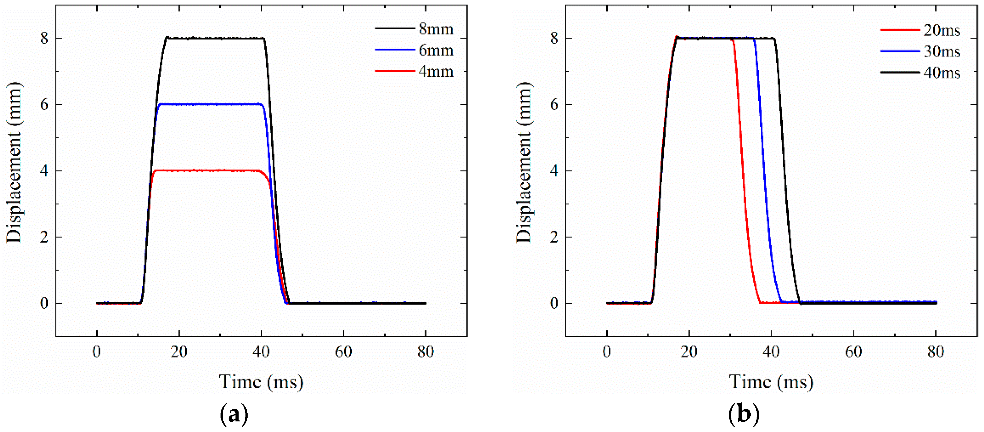
4.2.2. Cooperative Drive Mode
5. Conclusions
- In CELA, MCELA (which has linear output force and good control performance) is the main driving part. As the auxiliary driving component, MIELA provides end-holding force and selective driving power.
- A multi-mode motion coordination control strategy is established. When the load is large, the two driving parts are energized, and the starting force can be as high as 574.92 N. When the load is small, MCELA is energized alone, and MIELA moves with it to reduce the power consumption of the system.
- At the end of the stroke, CELA has a passive holding force of 229.25 N, which means that additional current is no longer required to counter the disturbance of the gas load during the on/off phase of holding. Thus, it can effectively reduce energy consumption.
- Under different motion modes, CELA can achieve continuous adjustable duration and maximum lift, and has good dynamic characteristics. At the same time, the steady-state error can be kept within ±0.02 mm, with high control accuracy.
Author Contributions
Funding
Institutional Review Board Statement
Informed Consent Statement
Data Availability Statement
Conflicts of Interest
References
- Su, W.; Zhang, Z.; Liu, R.; Qiao, Y. Development Trend for Technology of Vehicle Internal Combustion Engine. Chin. J. Eng. Sci. 2018, 20, 97. [Google Scholar] [CrossRef]
- Su, W. Advanced high density-low temperature combustion theory and technology. Trans. CSICE 2008, 26, 1–8. [Google Scholar]
- Moon, S. Strategies to realize 45% thermal efficiency of gasoline engines. J. Korean Soc. Automot. Eng. 2016, 38, 16–20. [Google Scholar]
- Xiao, M.; Chen, H. A study on reducing the NOx emission of the L21/31 medium-speed marine diesel engine for IMO tier emission legislation. Appl. Mech. Mater. 2013, 291, 1920–1924. [Google Scholar] [CrossRef]
- Lou, Z.; Zhu, G. Review of Advancement in Variable Valve Actuation of Internal Combustion Engines. Appl. Sci. 2020, 10, 1216. [Google Scholar] [CrossRef] [Green Version]
- Lu, Y.; Li, J.; Xiong, L.; Li, B. Simulation and Experimental Study of a Diesel Engine Based on an Electro-Hydraulic FVVA System Optimization. J. Energy Resour. Technol. 2020, 142, 1–10. [Google Scholar] [CrossRef]
- Lu, Y.; Tan, C.; Ge, W.; Li, B.; Lu, J. Improved Sliding Mode-Active Disturbance Rejection Control of Electromagnetic Linear Actuator for Direct-Drive System. Actuators 2021, 10, 138. [Google Scholar] [CrossRef]
- Pavlenko, A.; Gil’Miyarov, K.R.; Bol’Shenko, I.A. Electromagnetic drive valve control of the gas-distribution gear of an internal-combustion engine. Russ. Electr. Eng. 2014, 85, 298–304. [Google Scholar] [CrossRef]
- You, J.; Zhang, K.; Zhu, Z.; Liang, H. Novel Design and Research for a High-retaining-force, Bi-directional, Electromagnetic Valve Actuator with Double-layer Permanent Magnets. J. Magn. 2016, 21, 65–71. [Google Scholar] [CrossRef]
- Liu, L.; Chang, S.; Dai, J. Optimization analysis of electromagnetic linear actuator’s radial array permanent magnets. Int. J. Appl. Electromagn. Mech. 2015, 47, 441–451. [Google Scholar]
- Mercorelli, P. Robust Adaptive Soft Landing Control of an Electromagnetic Valve Actuator for Camless Engines. Asian J. Control. 2016, 18, 1299–1312. [Google Scholar] [CrossRef]
- Karunanidhi, S.; Singaperumal, M. Design, analysis and simulation of magnetostrictive actuator and its application to high dynamic servo valve. Sens. Actuators A Phys. 2010, 157, 185–197. [Google Scholar] [CrossRef]
- Pancharoen, K.; Zhu, D.; Beeby, S. Temperature dependence of a magnetically levitated electromagnetic vibration energy harvester. Sens. Actuators A: Phys. 2017, 256, 1–11. [Google Scholar] [CrossRef] [Green Version]
- Fan, X.; Dai, J.; Lu, J.; Xu, H.; Tan, C. Kinetic behavior evaluation of electromagnetic valve train subject to exhaust gas force. Appl. Therm. Eng. 2020, 171, 115097. [Google Scholar] [CrossRef]
- Tan, C.; Ge, W.; Fan, X.; Lu, J.; Li, B.; Sun, B. Bi-stable actuator measurement method based on voice coil motor. Sens. Actuators A Phys. 2019, 285, 59–66. [Google Scholar] [CrossRef]
- Cope, D.; Wright, A.; Corcoran, C.J.; Pasch, K.; Fischer, D. Fully Flexible Electromagnetic Valve Actuator: Design, Modeling, and Measurements; SAE Intenational: Pittsburgh, PA, USA, 2008. [Google Scholar] [CrossRef] [Green Version]
- Waindok, A.; Tomczuk, B.; Koteras, D. Modeling of Magnetic Field and Transients in a Novel Permanent Magnet Valve Actuator. Sensors 2020, 20, 2709. [Google Scholar] [CrossRef]
- Yang, Y.-P.; Liu, J.-J.; Ye, D.-H.; Chen, Y.-R.; Lu, P.-H. Multiobjective Optimal Design and Soft Landing Control of an Electromagnetic Valve Actuator for a Camless Engine. IEEE/ASME Trans. Mechatron. 2012, 18, 963–972. [Google Scholar] [CrossRef]
- Aslam, J.; Li, X.-H.; Janjua, F.K. Design of a hybrid magnetomotive force electromechanical valve actuator. Front. Inf. Technol. Electron. Eng. 2017, 18, 1635–1643. [Google Scholar] [CrossRef]
- Tan, C.; Li, B.; Ge, W. Thermal quantitative analysis and design method of bi-stable permanent magnet actuators based on multiphysics methodology. IEEE Trans. Ind. Electron. 2019, 67, 7727–7735. [Google Scholar] [CrossRef]
- Shao, D.; Sichuan, X.; Du, A. Research on a New Electromagnetic Valve Actuator Based on Voice Coil Motor for Automobile Engines; SAE MOBILUS: Pittsburgh, PA, USA, 2017. [Google Scholar] [CrossRef]
- Hoffman, B. Fully Variable Valve actuation with electromagnetic Linear Motor. SIA Conf. Var. Valve Actuation 2006, 30, 1–8. [Google Scholar]
- Mercorelli, P. A Two-Stage Sliding-Mode High-Gain Observer to Reduce Uncertainties and Disturbances Effects for Sensorless Control in Automotive Applications. IEEE Trans. Ind. Electron. 2015, 62, 5929–5940. [Google Scholar] [CrossRef]
- Schernus, C.; Van Der Staay, F.; Janssen, H.; Neumeister, J.; Vogt, B.; Donce, L.; Estlimbaum, I.; Nicole, E.; Maerky, C. Modeling of Exhaust Valve Opening in a Camless Engine; SAE International: Pittsburgh, PA, USA, 2002. [Google Scholar] [CrossRef]
- Fan, X.; Yin, J.; Su, S.; Pang, H.; Song, Y. Loss analysis of electromagnetic valve train under different service conditions. Int. J. Appl. Electromagn. Mech. 2021, 66, 461–473. [Google Scholar] [CrossRef]
- Li, Z.; Wu, Q.; Liu, B.; Gong, Z. Optimal Design of Magneto-Force-Thermal Parameters for Electromagnetic Actuators with Halbach Array. Actuators 2021, 10, 231. [Google Scholar] [CrossRef]
- Liu, L.; Chang, S. Improvement of valve seating performance of engine’s electromagnetic valvetrain. Mechatronics 2011, 21, 1234–1238. [Google Scholar] [CrossRef]
- Kim, J.; Joo, S.; Hahn, S.; Hong, J.; Kang, D.; Koo, D. Static Characteristics of Linear BLDC Motor Using Equivalent Magnetic Circuit and Finite Element Method. IEEE Trans. Magn. 2004, 40, 742–745. [Google Scholar] [CrossRef]
- Fan, X.; Chang, S.; Lu, J.; Liu, L.; Yao, S.; Xiao, M. Energy consumption investigation of electromagnetic valve train at gas pressure conditions. Appl. Therm. Eng. 2018, 146, 768–774. [Google Scholar] [CrossRef]


| Item | Value | Unit | |
|---|---|---|---|
| MCELA | Height | 113.9 | mm |
| Conductor diameter | 0.67 | mm | |
| Coil turn | 240 | — | |
| Resistance | 1.27 | Ω | |
| Inductance | 6.02 × 10⁻⁴ | H | |
| MIELA | Height | 52 | mm |
| Conductor diameter | 0.85 | mm | |
| Coil turn | 534 | — | |
| Resistance | 2.25 | Ω | |
| Inductance | 7.69 × 10⁻³ | H | |
| CELA | Total height | 209.4 | mm |
| Mover mass | 188.6 | g | |
| Stroke | 8 | mm |
Publisher’s Note: MDPI stays neutral with regard to jurisdictional claims in published maps and institutional affiliations. |
© 2021 by the authors. Licensee MDPI, Basel, Switzerland. This article is an open access article distributed under the terms and conditions of the Creative Commons Attribution (CC BY) license (https://creativecommons.org/licenses/by/4.0/).
Share and Cite
Fan, X.; Yin, J.; Lu, Q. Design and Analysis of a Novel Composited Electromagnetic Linear Actuator. Actuators 2022, 11, 6. https://doi.org/10.3390/act11010006
Fan X, Yin J, Lu Q. Design and Analysis of a Novel Composited Electromagnetic Linear Actuator. Actuators. 2022; 11(1):6. https://doi.org/10.3390/act11010006
Chicago/Turabian StyleFan, Xinyu, Jie Yin, and Qinfen Lu. 2022. "Design and Analysis of a Novel Composited Electromagnetic Linear Actuator" Actuators 11, no. 1: 6. https://doi.org/10.3390/act11010006
APA StyleFan, X., Yin, J., & Lu, Q. (2022). Design and Analysis of a Novel Composited Electromagnetic Linear Actuator. Actuators, 11(1), 6. https://doi.org/10.3390/act11010006