Article

Design and Analysis of a Novel Composited Electromagnetic Linear Actuator

1
College of Electrical Engineering, Zhejiang University, Hangzhou 310027, China
2
School of Energy and Power, Jiangsu University of Science and Technology, Zhenjiang 212100, China
*
Author to whom correspondence should be addressed.
Actuators 2022, 11(1), 6; https://doi.org/10.3390/act11010006
Submission received: 15 November 2021 / Revised: 27 December 2021 / Accepted: 27 December 2021 / Published: 29 December 2021
(This article belongs to the Section Actuators for Land Transport)

Abstract

:
Electromagnetic linear actuators, as key executive components, have a vital impact on the performance of fully flexible variable valve trains. Considering that the conventional moving coil electromagnetic linear actuator (MCELA) has the disadvantages of low force density and a lack of end-passive self-holding ability, a novel composited electromagnetic linear actuator (CELA) is proposed by combining the performance advantages of MCELA and moving iron electromagnetic linear actuator (MIELA) in this work. Firstly, the structure and magnetic circuit design scheme of the proposed actuator are introduced and the finite element simulation model is established. The magnetic field distribution and force characteristics of the actuators are assessed by finite element simulation. Secondly, the construction of the prototype of the actuator is outlined, based on which the feasibility of the design scheme and the steady-state performance of the actuator are verified. Finally, the coordinated control strategy is proposed to realize the multi motion coordination control of the actuator. The research results show that the maximum starting force of the CELA with the end-passive self-holding ability is 574.92 N while the holding force can approach 229.25 N. Moreover, the CELA is proven to have excellent dynamic characteristics and control precision under different motion modes and to have an improved adaptability to the complex working conditions of internal combustion engines.

1. Introduction

After more than 100 years of development, internal combustion engines are widely used in various fields such as the automobile, ship, energy and national defense sectors, and play an important role in national economic development and national defense construction owing to its incomparable advantages in energy density, thermal efficiency, fuel flexibility and reliability [1,2,3,4]. The large-scale application of internal combustion engines entails massive consumption of fossil energy and causes environmental pollution to a certain extent. Therefore, the development of new, efficient, green and clean technologies has become the focus of the internal combustion engine industry all over the world. In particular, the fully flexible variable valve technology can replace the traditional camshaft mechanism and realize the independent, real-time and continuous movement regulation of inlet and exhaust valves in the whole range of working conditions through motion servo control, which has a great potential to improve the efficiency of internal combustion engines and reduce emissions [5,6].
The electromagnetic valve train is a typical representative of fully flexible variable valve technology, and the electromagnetic linear actuator is the core of the electromagnetic valve train [7,8,9,10]. In recent years, the electromagnetic linear actuator has played an increasingly important role in many industrial applications [11,12], such as service valves [13], and aeronautical and fluid control systems [11]. With the rapid development of high-magnetic-energy rare-earth permanent-magnet materials, manufacturing technology and motion control theory in recent years, the response, accuracy and other motion servo performance and structural compactness of electromagnetic linear actuators have been continuously improved. However, many challenges are still faced under the complex and changeable working conditions of internal combustion engines. In particular, when the exhaust valve is opened, the high pressure gas load in the cylinder will seriously affect the dynamic characteristics of the actuator, resulting in the decline of the thermal cycle quality of the internal combustion engine [14].
As the mainstream driving unit of valve trains, MIELA has the advantages of compact structure and high force density [15], but its single electric excitation type will lead to high energy consumption. The American company Engineering Matters, and Waindok, Yang and Professor Li Xinghu’s team proposed hybrid excitation schemes with better driving efficiency and considerable, end-passive self-holding capability [16,17,18,19,20]. However, the inherent nonlinear output driving force of MIELA limited the dynamic performance and control accuracy of the mechanism [21]. As with MIELA, the moving magnetic type was also based on the principle of minimum reluctance in the magnetic circuit. The German company Compact Dynamic [22] and Professor Mercorelli’s team [23] proposed a variable valve train scheme based on moving magnetic actuator. However, for the reason that its mover was a permanent magnet, the magnetic field changed obviously in the working process, which increased the difficulty of control.
In recent years, MCELA has attracted extensive attention. The working magnetic field of MCELA is generated by the permanent magnet, and the distribution does not change significantly. This kind of actuator has linear output force, fast response and good control performance. However, MCELA has a low force density, and its dynamic performance needs to be improved when facing high-pressure exhaust gas in the cylinder of internal combustion engines [24,25], and it also lacks end-passive self-holding capacity, which will lead to increased energy consumption.
To this end, a composited electromagnetic linear actuator with fast response, high efficiency and energy saving features (CELA) is proposed in this paper. In the following, the theoretical analysis and finite element simulation analysis will be carried out on the main structures (MCELA and MIELA) of CELA. Meanwhile, the coordinated control strategy is proposed, and the dynamic performance test is carried out to verify the feasibility of the composited structure.

2. System Structure Design

Figure 1 shows the structure of the composited augmentation-type electromagnetic linear actuator, which is mainly composed of two parts: MCELA and MIELA. They are connected in series, and are fixed with each other through the connecting baffle. Their movers are rigidly connected by mover connecting rod. Two compression springs are fixed in a constant compression state.
MCELA is the main driving component whose coil bracket is directly connected with the valve and the valve motion control is realized by controlling the coil current. By adopting the Halbach array [26,27] in the internal magnetic field to strengthen the air gap magnetic field strength, MCELA has the characteristics of linear output force and good control performance.
MIElA is an auxiliary driving component based on the principle of minimum reluctance, and it is connected with the coil bracket of MCELA to follow its movement. In addition, MIELA has end-passive self-holding capacity.
The working principle of CELA can be divided into two modes according to the magnitude of gas load under different working conditions: The cooperative drive control is carried out when the load is large. The coils of MCELA and MIELA are both powered on, and the electromagnetic force they output in the same direction drives the valve. At this point, MIELA acts as the power assistance and the driving capacity of the system is improved. When the load is small, only MCELA is powered on, which outputs electromagnetic force to drive the air valve. At this point, MIELA follows passively, and the system energy consumption is reduced.
The CELA combines the performance advantages of MCELA and MIELA, and has the following characteristics:
(1)
High efficiency and energy-saving capacity: the actuator has a large driving force to meet the needs of various occasions, and it also has end-passive self-holding capacity and saves the electric energy that is needed to overcome the gas pressure at the end of the stroke.
(2)
High precision: through the integrated design and collaborative control of MCELA and MIELA, the control accuracy of CELA is improved.
In order to decouple MCELA and MIELA electromagnetically, it is necessary to simplify the complexity of the model and design scheme. In the integrated design of the composite structure, they have no contact with each other. The preliminary simulation analysis shows that the magnetic field interference between them can be ignored. Therefore, the two are first analyzed independently, then the force characteristics of the composited structure are studied and verified by means of experiments.

2.1. The MCELA

The MCELA is composed of an inner and outer yoke, a coil, a coil bracket, an end cover and a permanent magnet, as shown in Figure 1.
The working magnetic field of the MCELA is generated by the permanent magnet, which is divided into a long permanent magnet (radial magnetization) and a short permanent magnet (axial magnetization), and the magnetic flux is the superposition of the magnetic flux generated by the long permanent magnet and the short permanent magnet. The working air gap is a cylinder with an inner diameter of r 1 and an outer diameter of r 2 . The coil moves up and down in the working air gap, which will produce an axial Lorentz force F through the magnetic field when the current I is applied.
By neglecting the leakage flux [28], the corresponding equivalent magnetic circuit can be simplified as shown in Figure 2. The figure illustrates the location of the magnetic flux ϕ l of the long permanent magnet and the magnetic flux ϕ s of the short permanent magnet in the air gap, where the arrow indicates the direction of the magnetic flux.
In Figure 2, R P represents the equivalent reluctance of the long permanent magnet. r P stands for the equivalent reluctance of the short permanent magnet. R O is the reluctance of the outer yoke. R E is the end cover’s reluctance. R G is the air gap’s reluctance. R I is the inner yoke’s reluctance. R O is the outer yoke’s reluctance. M and m represent the magnetomotive force of the long permanent magnet and the short permanent magnet, respectively.
According to the formula of the reluctance, the reluctance R G can be calculated as follow:
R G = r 1 r 2 d r 2 π r μ 0 l = l n r 2 l n r 1 2 π μ 0 l  
μ 0 is the air permeability and r is the radius of the cylinder in the working air gap, which ranges from r 1 to r 2 .
The magnetomotive forces of the long and short permanent magnets are as follows:
M = H c h m  
m = H c L s  
Compared with the air gap reluctance, the reluctance of the inner and outer yoke, end cover and permanent magnet is small and can be neglected. The magnetic flux in the air gap can be expressed as follows:
ϕ = H c h m R G + H c L s R G = 2 π μ 0 L l ( H c h m + H c L s ) l n r 2 l n r 1  
B = ϕ L l L 0 = 2 π μ 0 ( H c h m + H c L s ) L 0 ( l n r 2 l n r 1 )  
where H c is the magnetic coercive force of the PM and L 0 is the circumference of a single winding, which is equal to 2 π ( r 2 r 1 ) when taking the middle of the air gap as the winding radius.
The magnitude of electromagnetic force can be calculated by the Lorentz force formula.
F = B I L  
L is the length of coil wire and I is the current through the coil.

2.2. The MIELA

MIELA is mainly composed of an armature, an outer yoke, a magnetic guide ring, a coil bracket and a coil, as shown in Figure 3.
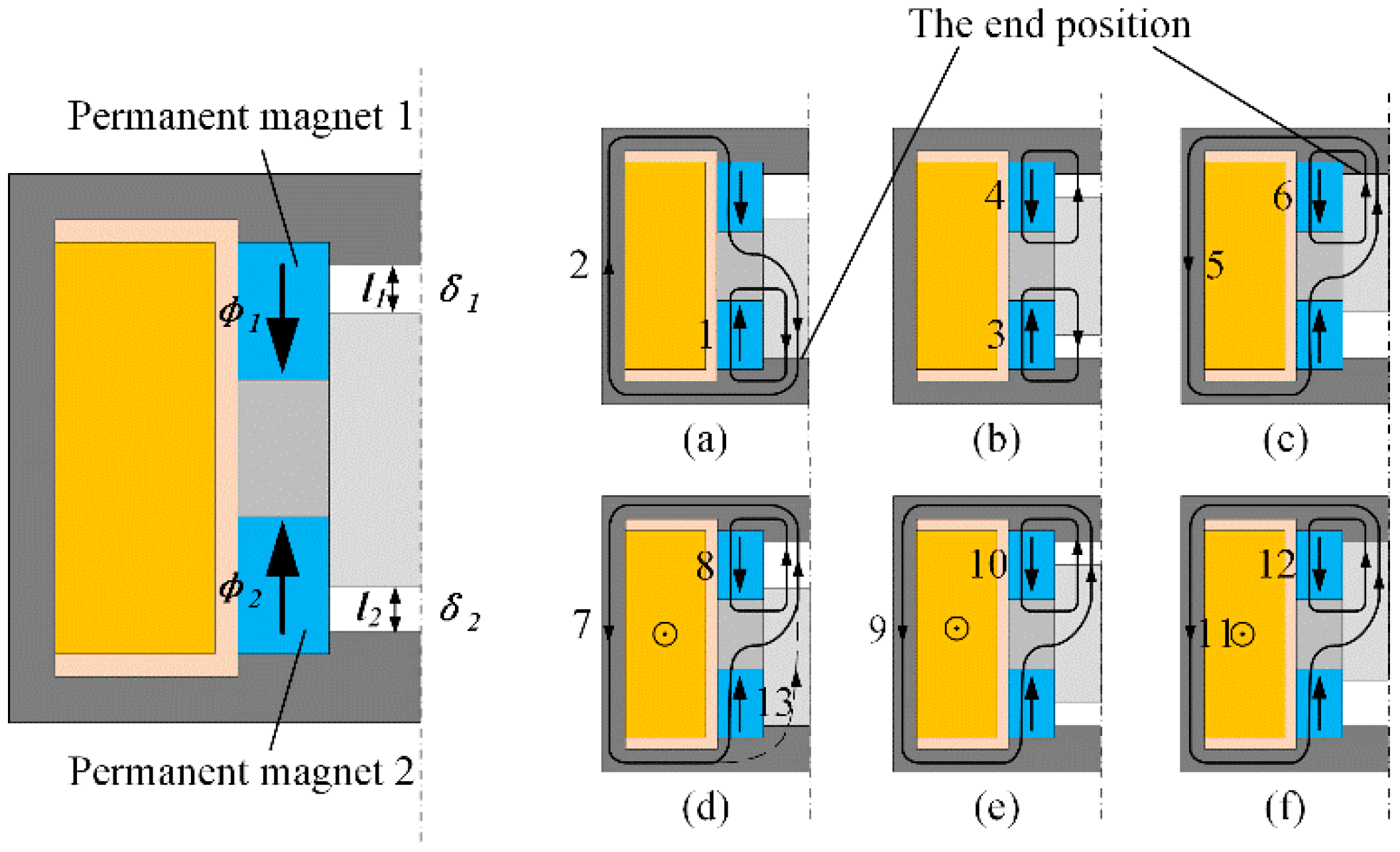
The representative stroke position, two ends and the middle are given as examples in Figure 3. For the convenience of description and distinction, the lower permanent magnet is called permanent magnet 1, and the upper permanent magnet is called permanent magnet 2. The magnetization direction of the permanent magnet is also marked in Figure 3. When the mover armature is at the beginning and end of the stroke, it is close to the outer yoke, which is called the end position.

2.2.1. In the Passive State, the Magnetic Flux of MIELA Is Composed of Permanent Magnets

Permanent magnet 1 generates one magnetic flux and permanent magnet 2 generates another magnetic flux. Magnetic flux 2 starts from permanent magnet 2 and enters the armature through the magnetic guide ring. Since the air reluctance is much greater than the armature reluctance, magnetic flux 2 goes down and merges with magnetic flux 1, passes through the armature and enters the lower outer yoke. The overall magnetic field at the lower end is strong, and the resultant force on the armature is downward.
When the armature is in the middle of the stroke, the magnetic flux generated by the two permanent magnets is completely symmetrical. The magnetic fields counteract each other and the armature is not stressed.
When the armature is at the upper end, it is completely symmetrical with the magnetic field at the lower end, and the armature is forced upward.
When the armature is in the stroke, the closer to the end, the greater the force exerted on the armature.

2.2.2. In the Active State, the Magnetic Flux of MIELA Is Composed of Permanent Magnet and Energized Coil

The armature moves from the lower end to the upper end, magnetic flux 7 (generated by the coil) is superimposed with magnetic flux 8 (generated by permanent magnet 2), and the armature is forced upward. As the armature moves closer to the upper end, the air gap decreases, the reluctance of the magnetic flux decreases, and the electromagnetic force becomes larger.
In particular, when the armature is located at the lower end, as shown in Figure 3d, with the increase in the excitation current, the saturation of the magnetic guide ring and the permanent magnet is significant, and an additional magnetic flux 13 appears. Moreover, magnetic flux 13 is strengthened with the increase in the current, which will weaken the output electromagnetic force.
When the MIELA is not electrified, the force on the moving armature is generated by the permanent magnets. According to Maxwell’s electromagnetic suction formula, the suction F 1 generated by the magnetic flux ϕ 1 of the permanent magnet through the working air gap δ 1 at one end can be expressed as follows:
F 1 = B 1 2 A 1 2 μ 0 = ϕ 1 2 2 μ 0 A 1
where F 1 is the suction generated by the permanent magnet at one end of the air gap δ 1 . B 1 is the magnetic induction of the permanent magnet in the working air gap δ 1 . A 1 is the end area of the armature in the working air gap δ 1 . μ 0 is the vacuum permeability, which has a clearly defined value of 4 π × 10 7   H / m , and ϕ 1 is the flux of the permanent magnet through working air gap δ 1 .
The suction at the other end can be expressed as follows:
F 2 = B 2 2 A 2 2 μ 0 = ϕ 2 2 2 μ 0 A 2  
where F 2 is the suction generated by the permanent magnet at one end of the air gap δ 2 , B 2 is the magnetic induction of the permanent magnet in the working air gap δ 2 , and A 2 is the end area of the armature in the working air gap δ 2 .
The resultant force acting on the armature can be calculated as follows:
F R = F 1 F 2 = B 1 2 A 1 2 μ 0 B 2 2 A 2 2 μ 0 = ϕ 1 2 2 μ 0 A 1 ϕ 2 2 2 μ 0 A 2
The reluctance of working air gaps δ 1 and δ 2 are expressed as follows:
R 1 = l 1 μ A 1 = l 1 μ 0 A 1  
R 2 = l 2 μ A 2 = l 2 μ 0 A 2
where R 1 is the reluctance of air gap δ 1 , R 2 is the reluctance of air gap δ 2 and μ is the air permeability. Since the air in the air gap is non-ferromagnetic material, it is generally considered that the permeability is equal to the vacuum permeability μ 0 .
Since the areas of both ends of the armature are equal ( A 1 = A 2 = A ), the following relationship can be obtained according to the principle of magnetic circuits:
B 1 B 2 = ϕ 1 ϕ 2 = R 2 R 1 = l 2 l 1
Formula (9) can also be simplified:
F R = F 1 F 2 = A ( B 1 2 B 2 2 ) 2 μ 0 = ϕ 1 2 ϕ 2 2 2 μ 0 A  
Substituting Formula (12) into Formula (13):
F R = ( 1 l 1 l 2 ) A B 1 2 2 μ 0 = ( l 2 l 1 1 ) A B 1 2 2 μ 0  
When l 1 = l 2 , F R = 0 , that is, when the armature is in the middle position, the length l 1 and l 2 of the air gap δ 1 and δ 2 at both ends are equal, and the resultant force of the armature is 0. When l 1 < l 2 , the suction is upward. The greater the difference between l 1 and l 2 , the greater the suction, and there is a maximum value A B 1 2 2 μ 0 . When l 1 > l 2 , the suction is downward. Similarly, the greater the difference between l 1 and l 2 , the greater the suction, and there is a maximum value A B 1 2 2 μ 0 in the opposite direction.
When the coil is energized, the control magnetic field generated by the coil and the polarized magnetic field generated by the permanent magnet are superimposed on each other. The resultant force of the armature is expressed as follows:
F R = A [ ( B 1 + B C ) 2 ( B 2 + B C ) 2 ] 2 μ 0
B C represents the magnetic induction intensity generated by the energized coil.
The above theoretical analysis has qualitative guiding significance. Through preliminary design, the main structural parameters of CELA are shown in Table 1.

3. Three-Dimensional Finite Element Simulation

Three-dimensional finite element (FE) models of MIELA and MCELA were established in the electromagnetic analysis software JMAG to calculate the magnetic field distribution of the actuator.

3.1. MCELA

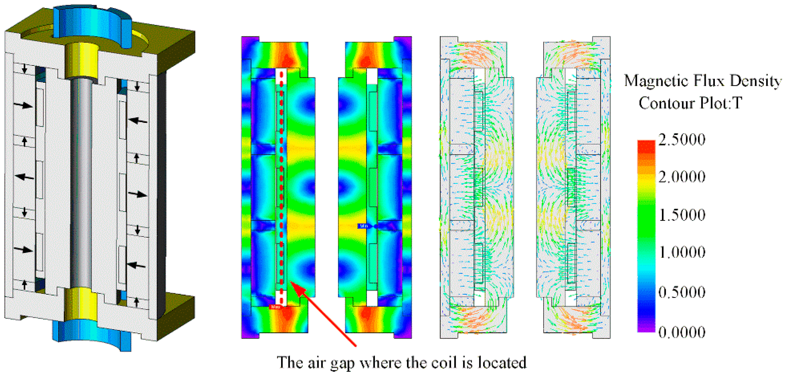
The finite element model of MCELA is shown in Figure 4. In this figure, the coil is in the middle of the stroke, and the arrow indicates the magnetization direction of the permanent magnet. A Halbach array is adopted in the permanent magnet arrangement, which effectively enhances the magnetic flux density on the side of the working air gap. The permanent magnet is made of NdFeB with good performance, and the end cover and inner and outer yoke are made of 1008 steel with strong magnetic conductivity. The coil bracket adopts light-weight, high-strength engineering plastics, which reduces the mass of the movers and reduces the impact on response speed, thus ensuring the strength and life of the actuator.
The magnetic field distribution of MCELA is shown in Figure 4. It can be seen that the magnetic flux distribution is denser and more uniform in the coil, the magnetic flux density is larger in the upper and lower end covers, and the inner and outer yokes are parallel to the axial magnetized permanent magnet.
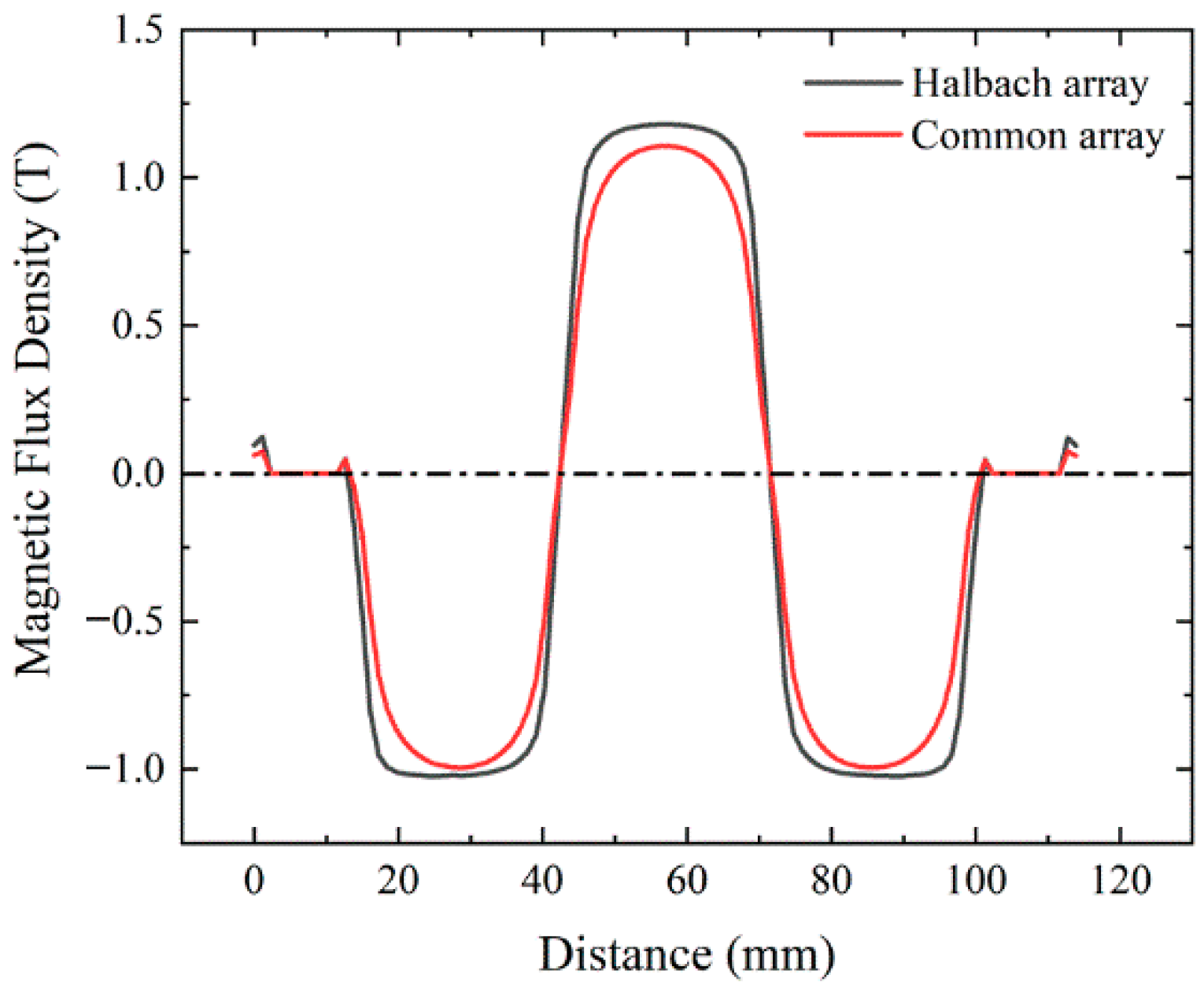
The magnetic flux density distribution curve at the air gap is shown in Figure 5. Compared with the common array, Halbach array has higher magnetic flux density, and the air gap magnetic flux density curve shows a flat peak within the coil motion range. Within this range, the magnetic flux density is relatively uniform, with smooth force characteristics and good control performance.
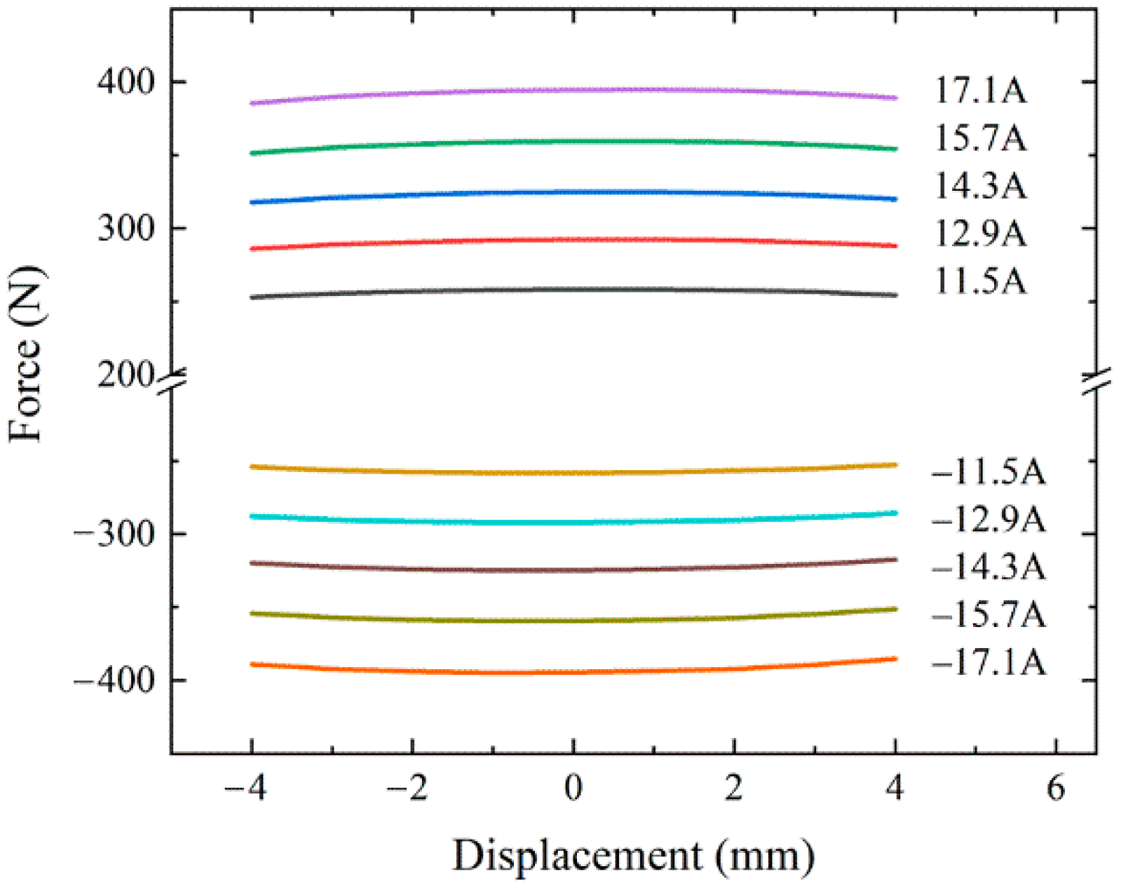
After the current is applied to MCELA, the magnetic field generated by the permanent magnet interacts with the current carrying coil to generate electromagnetic force, which drives MCELA to move in a straight line. Figure 6 shows the steady state force–displacement characteristic simulation curve of MCELA, which shows the relationship among the electromagnetic force, the coil position and the current. It can be seen from Figure 6 that under one current, the electromagnetic force basically tends to be stable, reaching the maximum at the middle position, and becomes slightly smaller at both ends, which is due to the end effect of MCELA. When the coil position changes, the fluctuation range of the electromagnetic force is about 16 N. Its characteristic curve has good linearity, which is conducive to obtaining good control performance. Therefore, MCELA can be used as the main driving component. The current is proportional to the electromagnetic force and its ratio is called the force constant, which is determined by the magnetic induction intensity and the effective length of the coil in the magnetic field. After simulation, the force constant is about 24.

3.2. MIELA

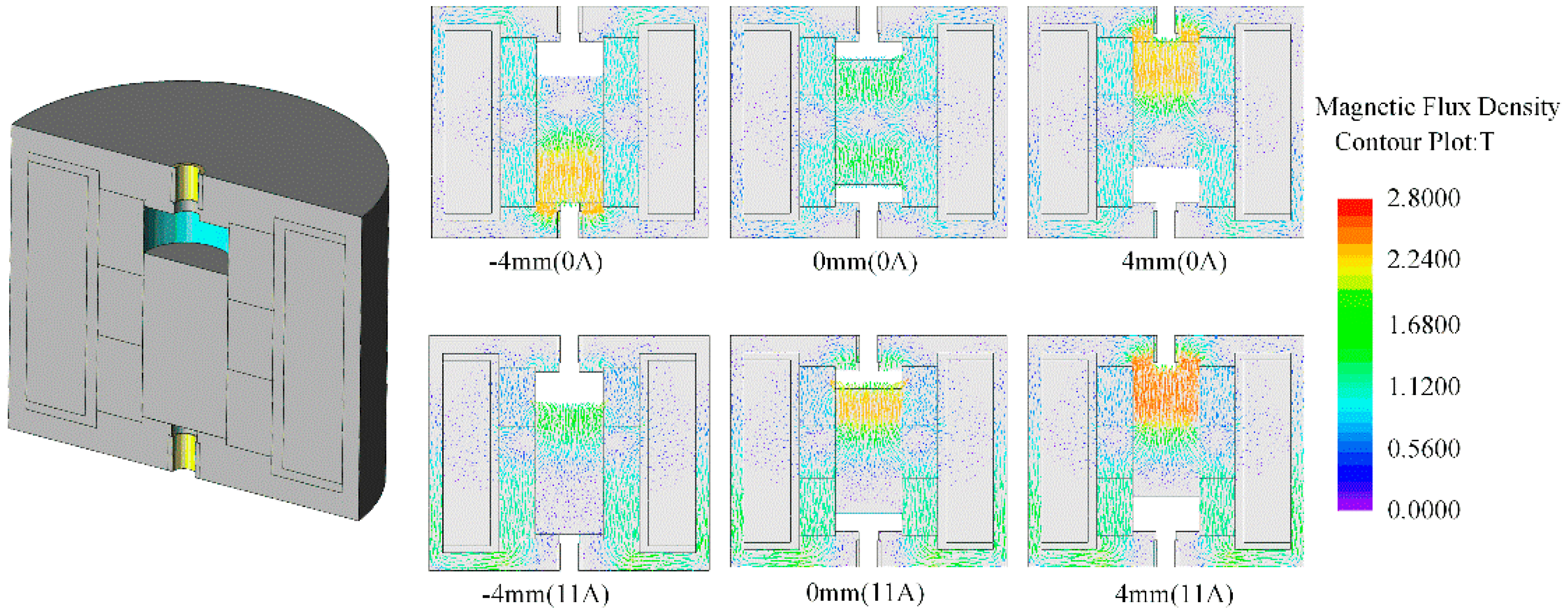
The finite element model of MIELA, with a stroke of 8mm, is shown in Figure 7. The armature, outer yoke and magnetic guide ring in the model are made of 1008 steel with strong magnetic conductivity and low cost, and the permanent magnet is made of NdFeB. The coil framework is made of lightweight and high-strength engineering plastics. Encryption was carried out on the meshes of the parts with dramatic magnetic field changes.
Figure 7 also shows the electromagnetic field distribution of the armature in different positions under the passive and active states obtained by simulation of the finite element model. It can be seen that the simulation results are consistent with the results of the previous theoretical analysis. The magnetic field changes sharply at the armature, the outer yoke seating position and the magnetic guide ring. The variation law of the magnetic field is the same as that obtained in the theoretical analysis and will not be repeated here.
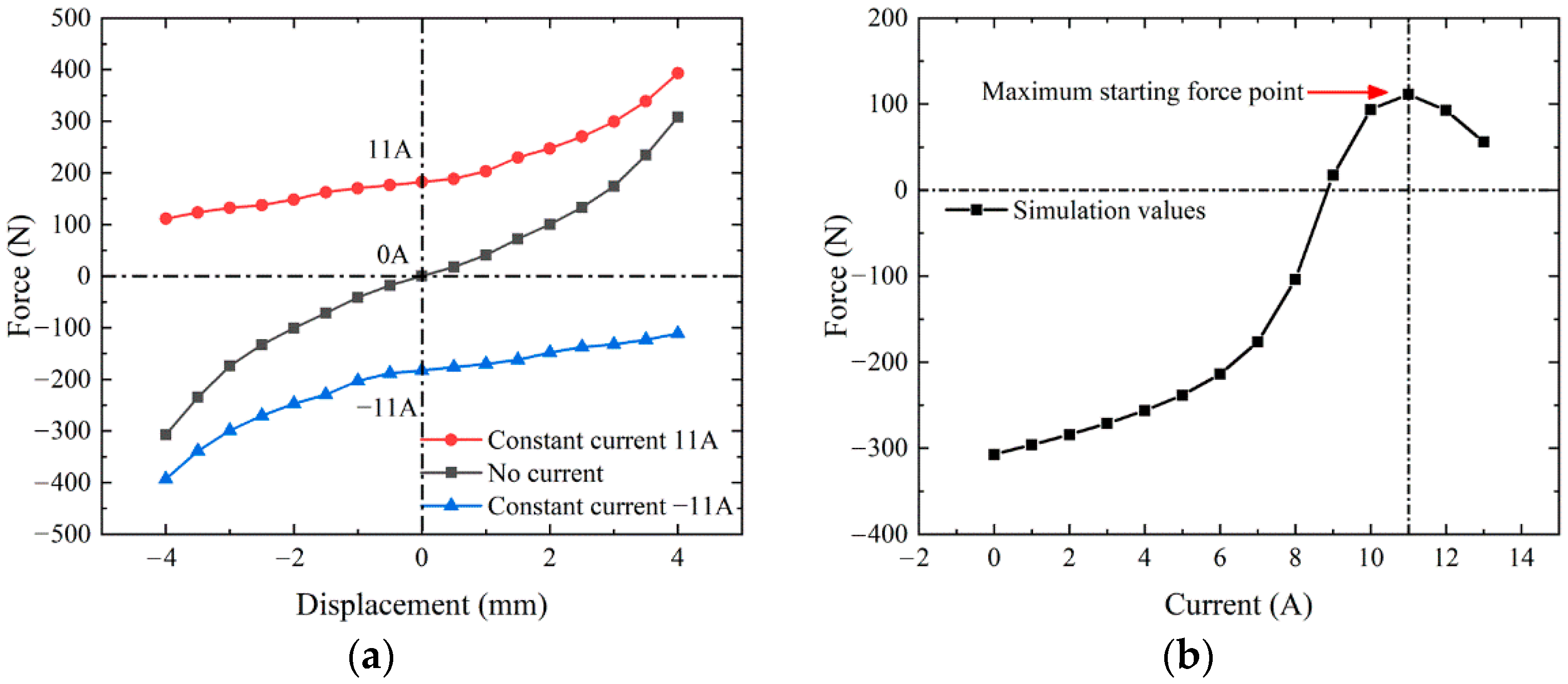
Figure 8 shows the steady-state force characteristic simulation curve of MIELA. The positive and negative values in the graph only represent the direction, regardless of the size.
Compared with MCELA, the force–displacement characteristic curve of MIELA is significantly nonlinear. The advantage of MIELA is that it can provide a certain passive holding force (the force on the armature when it is at the end in the passive state) at the end of the stroke, which is beneficial to reduce the energy consumption when remaining open or closed. MIELA can also provide a certain starting force (the force on the armature in the direction of the target when it is at the end in the active state).
Based on the above characteristics, it is feasible to use MIELA as an auxiliary driving component to provide passive self-holding ability and auxiliary force.

3.3. CELA

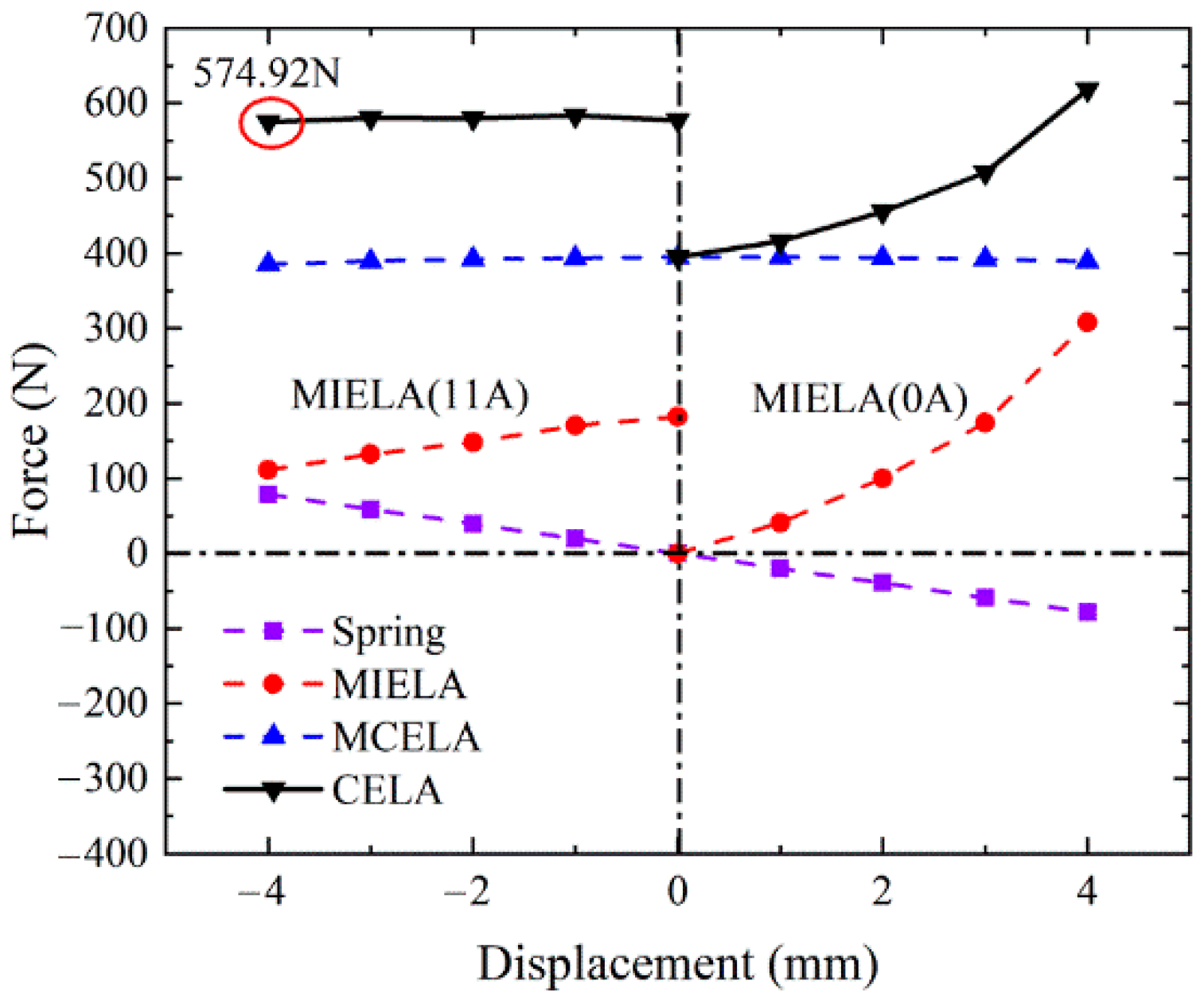
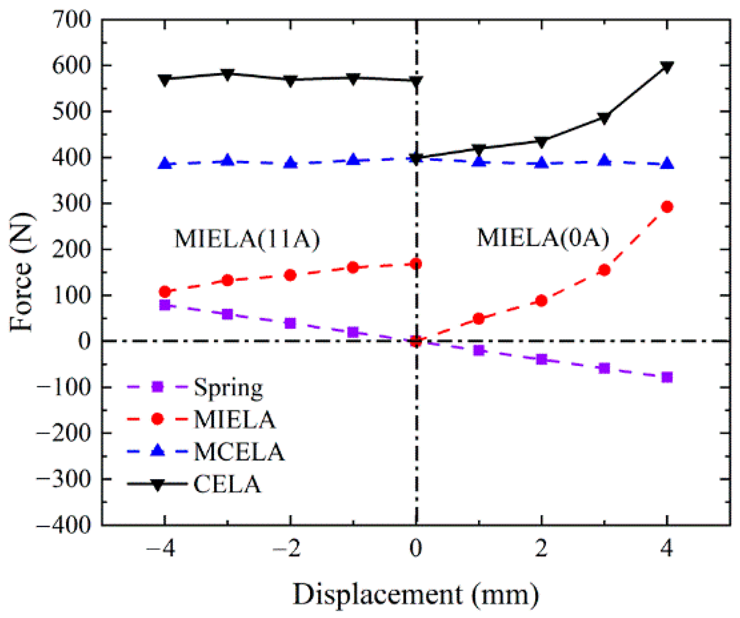
CELA is composed of the above two main components MCELA (the main driving component) and MIELA (the auxiliary driving component). The movers between MCELA and MIELA are rigidly connected, so their forces can be coupled directly. There are two symmetrical springs whose stiffness coefficient is 9.8 N/mm between them, and the precompression is 0.4 mm. The steady-state force characteristics of CELA can be obtained directly by combining them. The composite structure of CELA can take into account the performance advantages of MCELA and MIELA, with high starting force and end-passive self-holding force. The specific force characteristics are shown in Figure 9.
The starting force of CELA can reach 574.92 N. During the first half of CELA’s stroke, MIELA applies a constant current of 11A to achieve the maximum starting force and assist the start of the actuator, which is used to overcome the interference of the gas pressure in the cylinder. According to the previous research, the gas load force will decrease significantly in the second half stroke [29], and additional assistance will no longer be needed. Therefore, MIELA does not need to be powered on in the second half stroke, which can further reduce the energy consumption and the seating impact force. At the end of the stroke, the passive holding force of CELA is 229.25 N due to the effect of the spring force.

4. Verification of Experimental Results

4.1. The Steady State Experiment

The steady state force characteristic experimental bench of MCELA is shown in Figure 10. A digital signal processor with a clock frequency of 150 MHz is used as the digital controller. An S-type force sensor is adopted to measure the force signals and current sensor (ACS712) is employed to collect the current signals.
The actuator is fixed with bench pedestal, and connected with the S-type force sensor through the customized MCELA connector, and the other end of the force sensor is connected with the side plate through the threaded rod. The threaded rod can change the position of the mover by adjusting the nut, and the fixed position can be achieved by screwing the clamp nut. The laser displacement sensor is fixed at the other end of the bench pedestal and the laser directly strikes on the end face of the mover to observe the position of the mover. By cooperating with the threaded rod and nut, the position of the mover can be accurately adjusted.
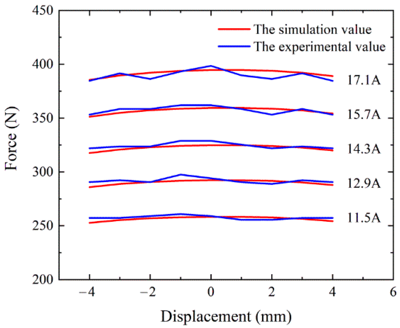
In this experiment, different currents are applied to MCELA to measure its electromagnetic force characteristics. Figure 11 shows the measured and simulated values of electromagnetic force characteristics at different positions under different currents. It can be seen that the curves obtained by experiment and simulation are in good agreement. At the same time, the electromagnetic force changes little with the position of the mover, which shows that the electromagnetic force is only slightly affected by the position of the mover. According to the results of simulation and experiment, the force constant is 24.
Through the same test method, the steady-state force displacement characteristic curve of MIELA can be obtained. As shown in Figure 12, the experimental data are in good agreement with the simulation results.
Finally, the steady-state force characteristic curve of CELA can be obtained, as shown in Figure 13.

4.2. The Dynamic Experiment

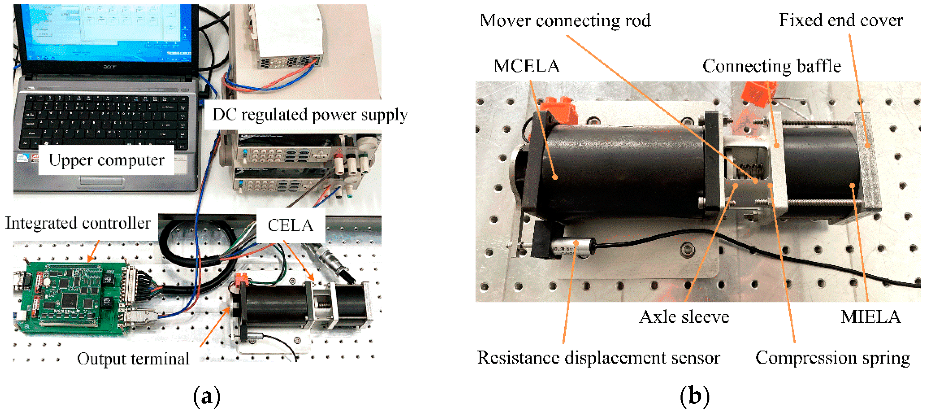
The dynamic experimental system is shown in Figure 14. A resistance displacement sensor is adopted to measure the motion of the actuator. Two pairs of PWM signals are generated from one event manager in the digital signal processor, and these are used to switch the IGBT H-bridge and offer MCELA and MIELA, respectively, with voltages.
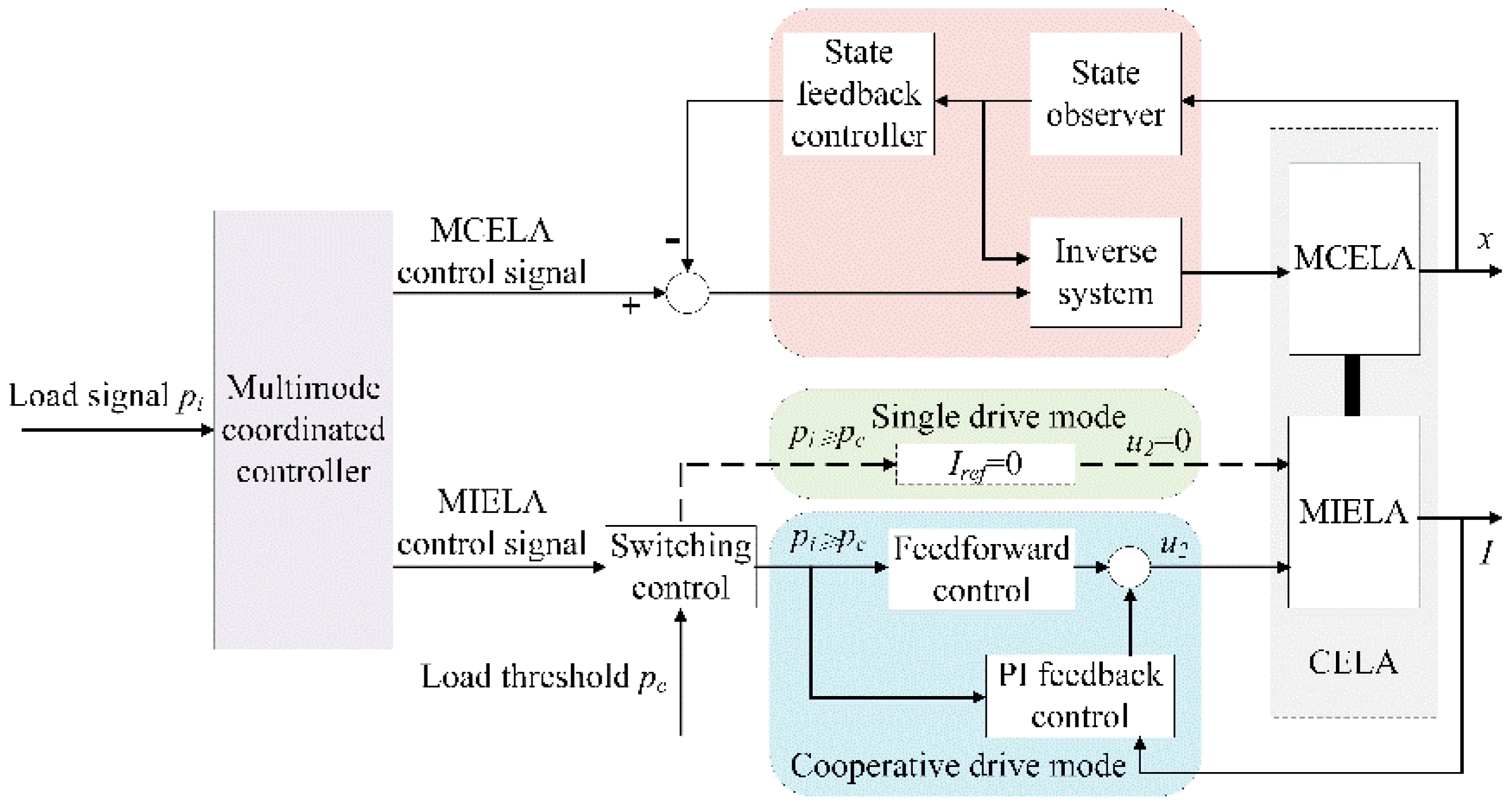
A multi-mode coordinated control strategy is designed for the motion control of CELA:
  • The cooperative drive mode is adopted when the load force is large and both actuator coils are energized to generate high driving force to overcome the load;
  • When the load force is small, the coil of MCELA is energized separately, and MIELA moves with it to reduce the energy consumption of the system.
The inverse system control method is adopted to realize the accurate control of the stroke position. Taking the MIELA model as the controlled object, the current control method of feedforward + PI feedback is adopted to realize the accurate control of the output force. The block diagram of the control system is shown in Figure 15. The design and implementation of the algorithm will be presented in another article, and will not be described here.
In order to facilitate the analysis of dynamic characteristics, it is necessary to set the right end point as the starting point (0 mm) and the left end point as the end point (8 mm).

4.2.1. Single Drive Mode

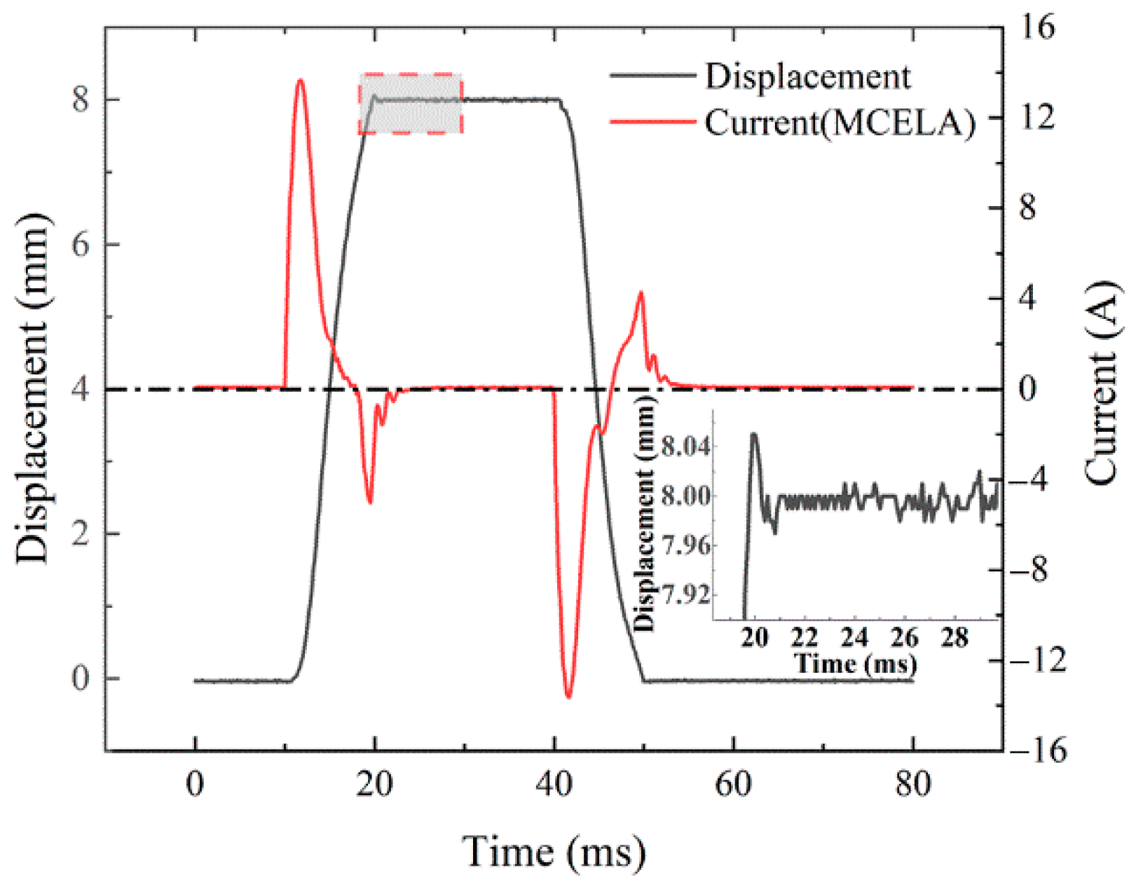
This working mode is implemented when MIELA is not powered on. Figure 16 shows the variation law of the mover displacement and MCELA current in the single drive mode. In the first half of the stroke, the current is positive, and the mover accelerates. In the second half of the stroke, the current is reversed, and the mover begins to decelerate, so that the effect of the seating buffer is achieved, and the maximum current reaches 13.66 A. The current is 0 A when the mover reaches the end position, which means that there is no power consumption due to the constant end-holding force. The transition time (the time required for the mover to move from 5% stroke to 95% stroke) is 6.9 ms. It can be seen from the local enlarged drawing that the actuator can accurately reach the specified stroke of 8 mm, and the steady-state error (the fluctuation range when it is stabilized at 8 mm) is within ±0.02 mm.
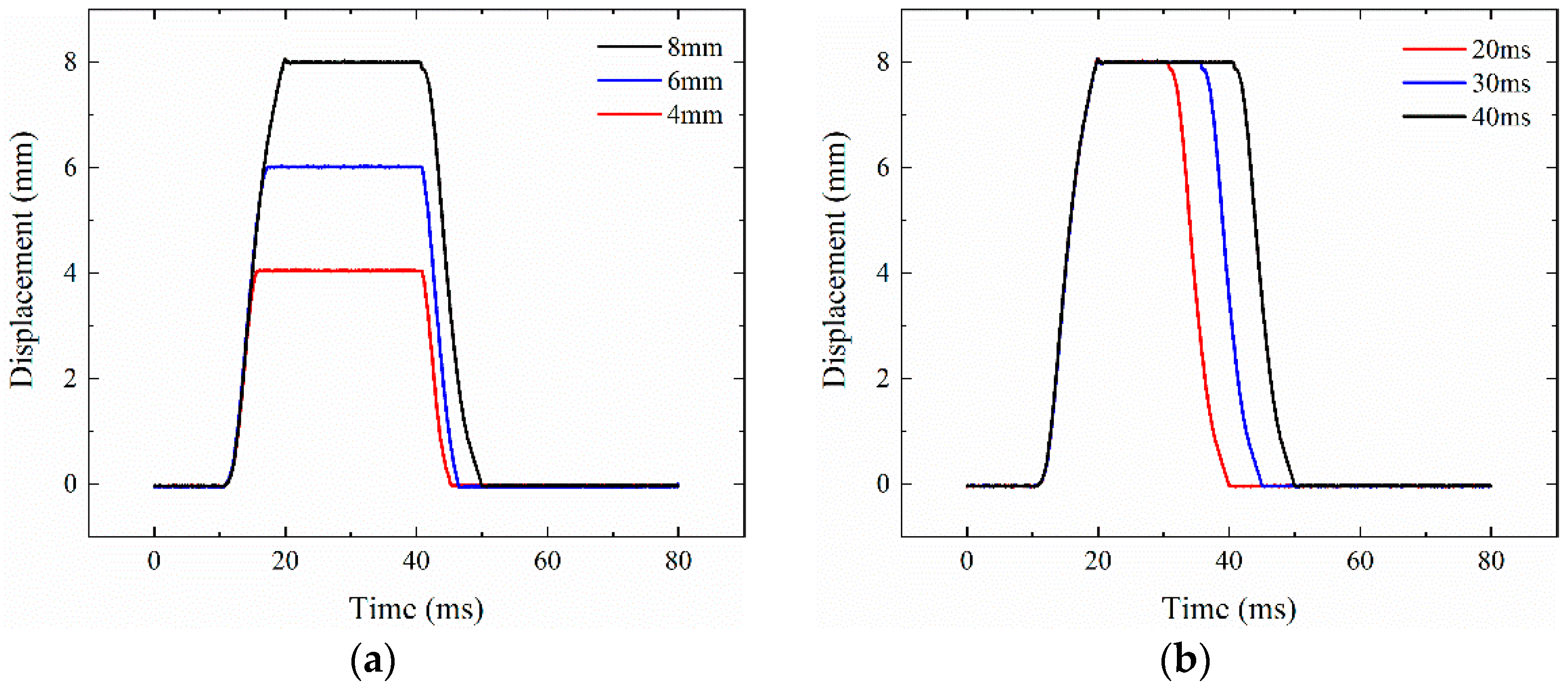
Unlike the traditional cam-driven valve mechanism, the variable valve’s electromagnetic drive can achieve full flexibility and adjustability. Through signal adjustment, the valve opening can be adjusted by adjusting the lift, as shown in Figure 17a.
The CELA duration (the period from start to the end of end retention) can also be flexibly adjusted. Figure 17b shows the experimental curve of the adjustable end-holding time of CELA in the single drive mode. The end-holding times of the mover are 10 ms, 15 ms and 20 ms, respectively.

4.2.2. Cooperative Drive Mode

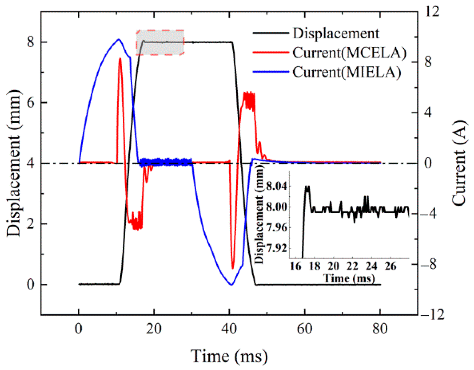
In the cooperative drive mode, both MCELA and MIELA are powered on at the same time. Figure 18 shows the current of MCELA and MIELA as well as the mover displacement curves. The current of MIELA is loaded in advance to achieve the ideal driving state, and the peak current is 9.80 A. The peak current of MCELA will decrease, by up to 8.30 A, due to the presence of no additional load force under the experimental condition. Meanwhile, the transition time of the actuator is reduced to 4.8 ms, which is shorter than that in the single drive mode. The actuator can accurately reach the specified stroke of 8 mm too, and the steady-state error is also within ±0.02 mm.
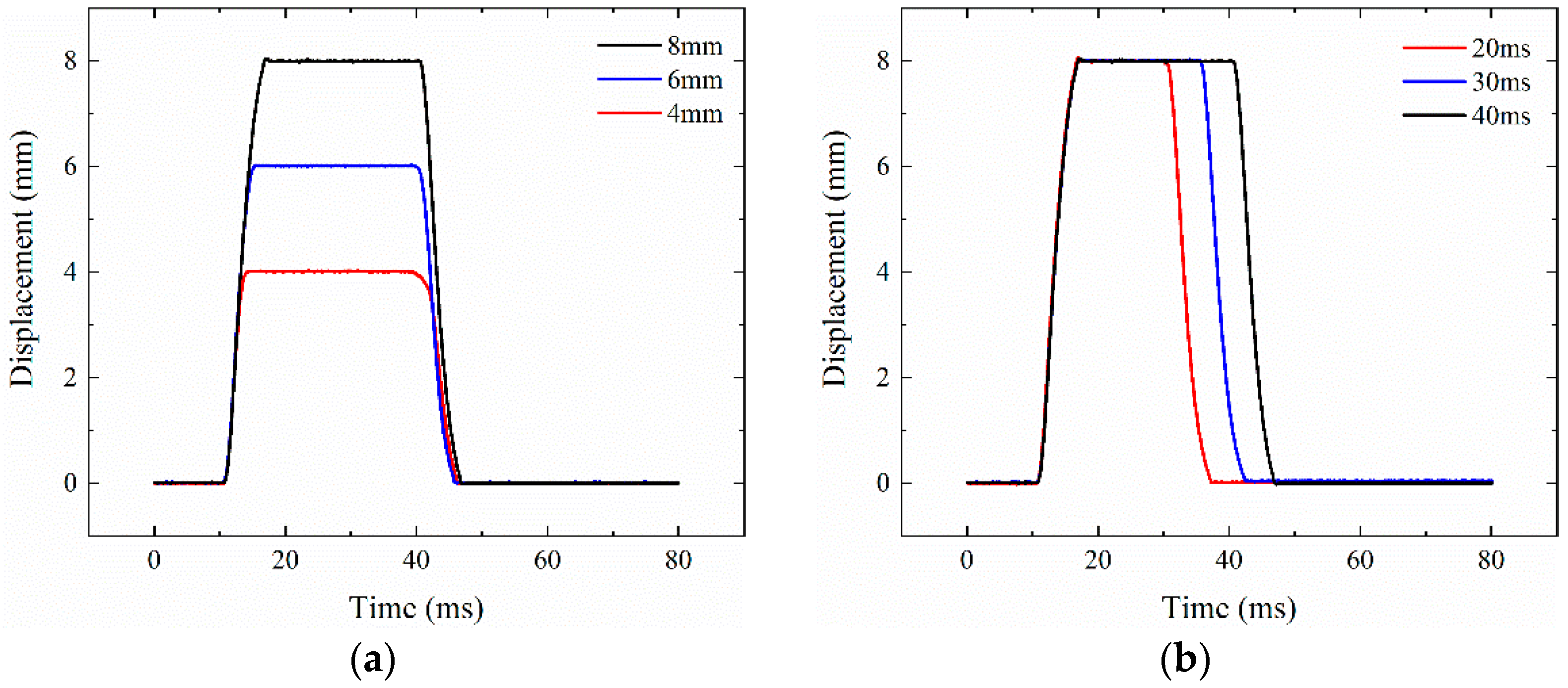
The cooperative drive mode can also be fully flexible and adjustable, and can still maintain a good motion law under the conditions of different displacements and different end-holding times, as shown in Figure 19.

5. Conclusions

A new structural scheme of a composited electromagnetic linear actuator (CELA), which combines the performance advantages of MCELA and MIELA, is proposed. The magnetic field distribution and force characteristics are analyzed through theoretical analysis and simulation analysis, and the multi-mode coordinated motion control strategy is established. An experimental platform was built to verify the steady and dynamic characteristics of CELA, indicating that the design scheme is feasible.
  • In CELA, MCELA (which has linear output force and good control performance) is the main driving part. As the auxiliary driving component, MIELA provides end-holding force and selective driving power.
  • A multi-mode motion coordination control strategy is established. When the load is large, the two driving parts are energized, and the starting force can be as high as 574.92 N. When the load is small, MCELA is energized alone, and MIELA moves with it to reduce the power consumption of the system.
  • At the end of the stroke, CELA has a passive holding force of 229.25 N, which means that additional current is no longer required to counter the disturbance of the gas load during the on/off phase of holding. Thus, it can effectively reduce energy consumption.
  • Under different motion modes, CELA can achieve continuous adjustable duration and maximum lift, and has good dynamic characteristics. At the same time, the steady-state error can be kept within ±0.02 mm, with high control accuracy.
Through the above work, the feasibility of the composited electromagnetic linear actuator is verified. In future works, multi-objective optimization and improvements in the coordinated control method will be carried out for the actuator.

Author Contributions

Conceptualization, X.F. and J.Y.; methodology, X.F., J.Y. and Q.L.; data curation, formal analysis, and simulation, X.F., J.Y. and Q.L.; writing—original draft preparation, X.F., J.Y. and Q.L.; writing—review and editing, X.F. and Q.L. All authors have read and agreed to the published version of the manuscript.

Funding

This work was funded by the China Postdoctoral Science Foundation, grant number 2020M681845; the Natural Science Foundation of Jiangsu Province, China, grant number BK20190972; and the Foundation of Key Laboratory Equipment Pre-Research, grant number 6142212190410.

Institutional Review Board Statement

Not applicable.

Informed Consent Statement

Not applicable.

Data Availability Statement

The data presented in this study are available on request from the corresponding author.

Conflicts of Interest

The authors declare no conflict of interest.

References

  1. Su, W.; Zhang, Z.; Liu, R.; Qiao, Y. Development Trend for Technology of Vehicle Internal Combustion Engine. Chin. J. Eng. Sci. 2018, 20, 97. [Google Scholar] [CrossRef]
  2. Su, W. Advanced high density-low temperature combustion theory and technology. Trans. CSICE 2008, 26, 1–8. [Google Scholar]
  3. Moon, S. Strategies to realize 45% thermal efficiency of gasoline engines. J. Korean Soc. Automot. Eng. 2016, 38, 16–20. [Google Scholar]
  4. Xiao, M.; Chen, H. A study on reducing the NOx emission of the L21/31 medium-speed marine diesel engine for IMO tier emission legislation. Appl. Mech. Mater. 2013, 291, 1920–1924. [Google Scholar] [CrossRef]
  5. Lou, Z.; Zhu, G. Review of Advancement in Variable Valve Actuation of Internal Combustion Engines. Appl. Sci. 2020, 10, 1216. [Google Scholar] [CrossRef] [Green Version]
  6. Lu, Y.; Li, J.; Xiong, L.; Li, B. Simulation and Experimental Study of a Diesel Engine Based on an Electro-Hydraulic FVVA System Optimization. J. Energy Resour. Technol. 2020, 142, 1–10. [Google Scholar] [CrossRef]
  7. Lu, Y.; Tan, C.; Ge, W.; Li, B.; Lu, J. Improved Sliding Mode-Active Disturbance Rejection Control of Electromagnetic Linear Actuator for Direct-Drive System. Actuators 2021, 10, 138. [Google Scholar] [CrossRef]
  8. Pavlenko, A.; Gil’Miyarov, K.R.; Bol’Shenko, I.A. Electromagnetic drive valve control of the gas-distribution gear of an internal-combustion engine. Russ. Electr. Eng. 2014, 85, 298–304. [Google Scholar] [CrossRef]
  9. You, J.; Zhang, K.; Zhu, Z.; Liang, H. Novel Design and Research for a High-retaining-force, Bi-directional, Electromagnetic Valve Actuator with Double-layer Permanent Magnets. J. Magn. 2016, 21, 65–71. [Google Scholar] [CrossRef]
  10. Liu, L.; Chang, S.; Dai, J. Optimization analysis of electromagnetic linear actuator’s radial array permanent magnets. Int. J. Appl. Electromagn. Mech. 2015, 47, 441–451. [Google Scholar]
  11. Mercorelli, P. Robust Adaptive Soft Landing Control of an Electromagnetic Valve Actuator for Camless Engines. Asian J. Control. 2016, 18, 1299–1312. [Google Scholar] [CrossRef]
  12. Karunanidhi, S.; Singaperumal, M. Design, analysis and simulation of magnetostrictive actuator and its application to high dynamic servo valve. Sens. Actuators A Phys. 2010, 157, 185–197. [Google Scholar] [CrossRef]
  13. Pancharoen, K.; Zhu, D.; Beeby, S. Temperature dependence of a magnetically levitated electromagnetic vibration energy harvester. Sens. Actuators A: Phys. 2017, 256, 1–11. [Google Scholar] [CrossRef] [Green Version]
  14. Fan, X.; Dai, J.; Lu, J.; Xu, H.; Tan, C. Kinetic behavior evaluation of electromagnetic valve train subject to exhaust gas force. Appl. Therm. Eng. 2020, 171, 115097. [Google Scholar] [CrossRef]
  15. Tan, C.; Ge, W.; Fan, X.; Lu, J.; Li, B.; Sun, B. Bi-stable actuator measurement method based on voice coil motor. Sens. Actuators A Phys. 2019, 285, 59–66. [Google Scholar] [CrossRef]
  16. Cope, D.; Wright, A.; Corcoran, C.J.; Pasch, K.; Fischer, D. Fully Flexible Electromagnetic Valve Actuator: Design, Modeling, and Measurements; SAE Intenational: Pittsburgh, PA, USA, 2008. [Google Scholar] [CrossRef] [Green Version]
  17. Waindok, A.; Tomczuk, B.; Koteras, D. Modeling of Magnetic Field and Transients in a Novel Permanent Magnet Valve Actuator. Sensors 2020, 20, 2709. [Google Scholar] [CrossRef]
  18. Yang, Y.-P.; Liu, J.-J.; Ye, D.-H.; Chen, Y.-R.; Lu, P.-H. Multiobjective Optimal Design and Soft Landing Control of an Electromagnetic Valve Actuator for a Camless Engine. IEEE/ASME Trans. Mechatron. 2012, 18, 963–972. [Google Scholar] [CrossRef]
  19. Aslam, J.; Li, X.-H.; Janjua, F.K. Design of a hybrid magnetomotive force electromechanical valve actuator. Front. Inf. Technol. Electron. Eng. 2017, 18, 1635–1643. [Google Scholar] [CrossRef]
  20. Tan, C.; Li, B.; Ge, W. Thermal quantitative analysis and design method of bi-stable permanent magnet actuators based on multiphysics methodology. IEEE Trans. Ind. Electron. 2019, 67, 7727–7735. [Google Scholar] [CrossRef]
  21. Shao, D.; Sichuan, X.; Du, A. Research on a New Electromagnetic Valve Actuator Based on Voice Coil Motor for Automobile Engines; SAE MOBILUS: Pittsburgh, PA, USA, 2017. [Google Scholar] [CrossRef]
  22. Hoffman, B. Fully Variable Valve actuation with electromagnetic Linear Motor. SIA Conf. Var. Valve Actuation 2006, 30, 1–8. [Google Scholar]
  23. Mercorelli, P. A Two-Stage Sliding-Mode High-Gain Observer to Reduce Uncertainties and Disturbances Effects for Sensorless Control in Automotive Applications. IEEE Trans. Ind. Electron. 2015, 62, 5929–5940. [Google Scholar] [CrossRef]
  24. Schernus, C.; Van Der Staay, F.; Janssen, H.; Neumeister, J.; Vogt, B.; Donce, L.; Estlimbaum, I.; Nicole, E.; Maerky, C. Modeling of Exhaust Valve Opening in a Camless Engine; SAE International: Pittsburgh, PA, USA, 2002. [Google Scholar] [CrossRef]
  25. Fan, X.; Yin, J.; Su, S.; Pang, H.; Song, Y. Loss analysis of electromagnetic valve train under different service conditions. Int. J. Appl. Electromagn. Mech. 2021, 66, 461–473. [Google Scholar] [CrossRef]
  26. Li, Z.; Wu, Q.; Liu, B.; Gong, Z. Optimal Design of Magneto-Force-Thermal Parameters for Electromagnetic Actuators with Halbach Array. Actuators 2021, 10, 231. [Google Scholar] [CrossRef]
  27. Liu, L.; Chang, S. Improvement of valve seating performance of engine’s electromagnetic valvetrain. Mechatronics 2011, 21, 1234–1238. [Google Scholar] [CrossRef]
  28. Kim, J.; Joo, S.; Hahn, S.; Hong, J.; Kang, D.; Koo, D. Static Characteristics of Linear BLDC Motor Using Equivalent Magnetic Circuit and Finite Element Method. IEEE Trans. Magn. 2004, 40, 742–745. [Google Scholar] [CrossRef]
  29. Fan, X.; Chang, S.; Lu, J.; Liu, L.; Yao, S.; Xiao, M. Energy consumption investigation of electromagnetic valve train at gas pressure conditions. Appl. Therm. Eng. 2018, 146, 768–774. [Google Scholar] [CrossRef]
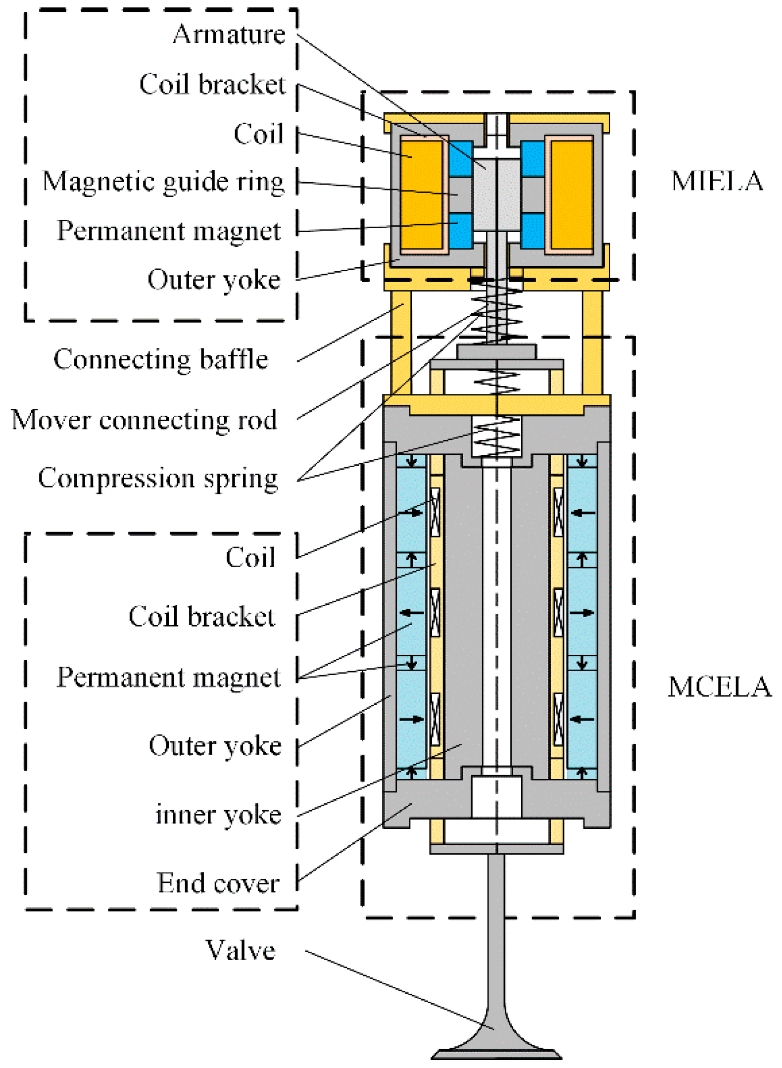
Figure 1. Structure of CELA.
Actuators 11 00006 g001
Figure 2. Magnetic Circuit of MCELA.
Actuators 11 00006 g002
Figure 3. Structure and magnetic circuit analysis diagram of MIELA.
Actuators 11 00006 g003
Figure 4. Magnetic flux density cloud and magnetic flux density vector plots of MCELA.
Actuators 11 00006 g004
Figure 5. Magnetic flux density distribution curve.
Actuators 11 00006 g005
Figure 6. Steady-state force–displacement characteristic simulation curve of MCELA.
Actuators 11 00006 g006
Figure 7. Structure and magnetic flux density vector plots of MIELA.
Actuators 11 00006 g007
Figure 8. Steady-state force characteristic simulation curve of MIELA: (a) force–displacement characteristic curve; (b) force–current characteristic curve.
Actuators 11 00006 g008
Figure 9. Steady state force–displacement characteristic simulation curve of CELA.
Actuators 11 00006 g009
Figure 10. Composition of the steady-state force characteristic experimental bench of MCELA.
Actuators 11 00006 g010
Figure 11. Steady-state force–displacement characteristic experimental curve of MCELA.
Actuators 11 00006 g011
Figure 12. Steady-state force characteristic experimental curve of MIELA: (a) force–displacement characteristic curve; (b) force–current characteristic curve.
Actuators 11 00006 g012
Figure 13. Steady-state force–displacement characteristic experimental curve of MIELA.
Actuators 11 00006 g013
Figure 14. Dynamic experimental system: (a) composition of the dynamic experimental system; (b) composition of the dynamic experimental bench of CELA.
Actuators 11 00006 g014
Figure 15. Block diagram of the experimental system.
Actuators 11 00006 g015
Figure 16. Variation curve of mover displacement and current in single drive mode.
Actuators 11 00006 g016
Figure 17. CELA can achieve full flexibility and adjustability in the single drive mode: (a) CELA lift is adjustable; (b) CELA duration is adjustable.
Actuators 11 00006 g017
Figure 18. Mover displacement and current variation curve in cooperative drive mode.
Actuators 11 00006 g018
Figure 19. CELA can achieve full flexibility and adjustability in cooperative drive mode: (a) CELA lift is adjustable; (b) CELA duration is adjustable.
Actuators 11 00006 g019
Table 1. The preliminary parameters of CELA.
ItemValueUnit
MCELAHeight113.9mm
Conductor diameter0.67mm
Coil turn240
Resistance1.27Ω
Inductance6.02 × 10−4H
MIELAHeight52mm
Conductor diameter0.85mm
Coil turn534
Resistance2.25Ω
Inductance7.69 × 10−3H
CELATotal height209.4mm
Mover mass188.6g
Stroke8mm
Publisher’s Note: MDPI stays neutral with regard to jurisdictional claims in published maps and institutional affiliations.