Article

Path Tracking Control of an Autonomous Tractor Using Improved Stanley Controller Optimized with Multiple-Population Genetic Algorithm

College of Engineering, China Agricultural University, Beijing 100083, China
*
Author to whom correspondence should be addressed.
Actuators 2022, 11(1), 22; https://doi.org/10.3390/act11010022
Submission received: 26 November 2021 / Revised: 7 January 2022 / Accepted: 10 January 2022 / Published: 11 January 2022

Abstract

:
To improve the path tracking accuracy of autonomous tractors in operation, an improved Stanley controller (IMP-ST) is proposed in this paper. The controller was applied to a two-wheel tractor dynamics model. The parameters of the IMP-ST were optimized by multiple-population genetic algorithm (MPGA) to obtain better tracking performance. The main purpose of this paper is to implement path tracking control on an autonomous tractor. Thus, it is significant to study this field because of smart agricultural development. According to the turning strategy of tractors in field operations, five working routes for tractors were designed, including straight, U, Ω, acute-angle and obtuse-angle routes. Simulation tests were conducted to verify the effectiveness of the proposed IMP-ST in tractor path tracking for all routes. The lateral root-mean-square (RMS) error of the IMP-ST was reduced by up to 36.84% and 48.61% compared to the extended Stanley controller and the original Stanley controller, respectively. The simulation results indicate that the IMP-ST performed well in guiding the tractor to follow all planned working routes. In particular, for the U and Ω routes, the two most common turning methods in tractor field operations, the path tracking performance of the IMP-ST was improved by 41.72% and 48.61% compared to the ST, respectively. Comparing and analyzing the e-Ψ and β-γ phase plane of the three controllers, the results indicate that the IMP-ST has the best control stability.

1. Introduction

The automatic navigation technology of agricultural vehicles is an important part of an intelligent agricultural system, which can effectively address labor shortages and inefficient production in agriculture. In the study of autonomous tractor navigation technology, path tracking is one of the key and difficult points that directly affects the operating accuracy of autonomous tractors. Therefore, research on navigation path tracking control algorithms of tractors is of great significance in improving the operation quality and achieving the autonomous operation of tractors.
In recent years, navigation path tracking control of tractor navigation has been studied by many scholars, and several control algorithms have been proposed, mainly including geometric/kinematic control [1,2], PID control [3,4], fuzzy control [5,6,7], sliding mode control [8], model predictive control [9,10] and optimal control [11,12]. Pure pursuit is an algorithm based on geometric/kinematic control and is the most widely used agricultural machine path tracking algorithm because of its simplicity and efficiency [13,14]. However, the path tracking effect is directly affected by the value of the forward-looking distance. To solve this problem, Li et al. proposed a path tracking method for tractors based on the fuzzy adaptive pure tracking model. It was combined with the kinematics model of tractors, and the forward-looking distance was adjusted online using the fuzzy adaptive algorithm [15]. Although the forward-looking distance studied by many scholars is tuned through various algorithms, it is often difficult to obtain both the stability and the tracking effect of the tractor [16].
Stanley is another efficient geometric control algorithm. It was proposed by the Stanford University team and applied in the DARPA Grand Challenge 2005. The team won the championship with an RMS of less than 0.1 m [17]. In contrast to the pure tracking algorithm, the Stanley controller does not need to find the optimal forward-looking distance. Moreover, the simple structure of this controller makes it easier to implement than other intelligent controllers. In a previous paper, Hoffmann et al. [17] proposed an extended Stanley controller considering the yaw rate to compensate for the lack of look-ahead distance. The extended version was considered and improved for application to the autonomous tractor in this paper.
The genetic algorithm (GA) is a highly parallel, random, and adaptive global optimization probabilistic search algorithm that was developed by referring to natural selection and evolution mechanisms in the biological world. The convergence criteria of this algorithm are met through selection, crossover, mutation, and iteration. Because of its simple structure, global search, and convenient implementation, the GA is widely used in controller parameter optimization [18], parameter identification [19], path optimization [20], and neural network optimization [21]. Feng et al. used a genetic algorithm to search for the PID controller parameters of robotic excavators to obtain improved tracking performance [22]. Meng et al. designed a new controller based on combining the linear quadratic regulator (LQR) and GA algorithm, and the path tracking performance of articulated dump trucks was improved [23]. However, the GA faces the problem of immature convergence. When the optimal solution is not found, the diversity of the individual structures in the population of the GA is decreased sharply. This problem is effectively solved with the multiple-population genetic algorithm (MPGA) by introducing a migration operator and multi-population coevolution. Lu et al. proposed an MPGA-based convolutional neural network for object visual detection, and the computational complexity and performance of the deep convolutional neural network were effectively balanced [24]. Reina et al. addressed the multitarget coverage difficulty using an MPGA on an unmanned aerial vehicle (UAV) network [25]. Compared with the classical GA, mountain climbing algorithm and particle swarm optimization (PSO) algorithm, the MPGA algorithm could achieve better global optimal results of multiple parameters. However, the topic of this study, an MPGA to tune the improved Stanley controller (IMP-ST) parameters for accurate path tracking of autonomous tractors, has seldom been researched to date.
The main purpose of this study is to develop an automatic steering controller for an autonomous tractor. To achieve better path tracking performance, the IMP-ST was proposed and developed. Firstly, the two-wheel dynamic model and five tractor working route models are established. Then, the path tracking strategies, including the Stanley controller (ST), extended Stanley controller (EXT-ST), and IMP-ST, are introduced carefully. The three controllers are optimized by MPGA to obtain the best parameters. Thirdly, the results of the simulation tests are analyzed and discussed. The conclusion of this study is presented finally.

2. Materials and Methods

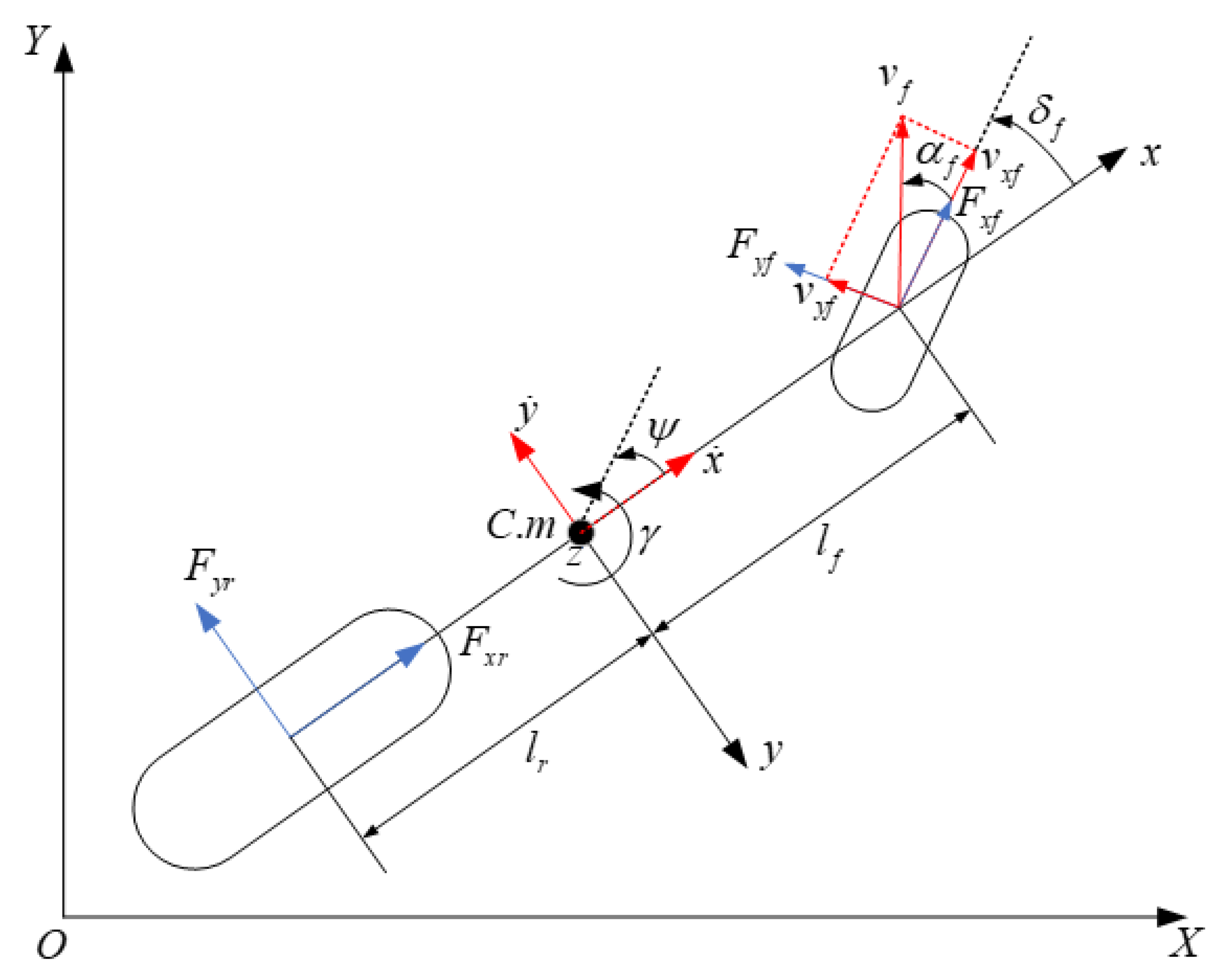
2.1. Tractor and Path Modelling

2.1.1. Two-Wheel Tractor Dynamic Model

A tractor usually runs at low speed in the course of path tracking operation, so it can be simplified as a two-wheel dynamic model in this paper. The vertical, roll, and pitch motion of the tractor are ignored, and the longitudinal, lateral, and yaw motion are considered. The 2-wheel dynamics model of the tractor is shown in Figure 1, where X-O-Y is the inertial coordinate system, which is fixed on the ground surface, and x-z-y is the tractor coordinate system. The origin of x-z-y is located at the center of the tractor mass, with the x axis along the direction the tractor is working, and the y axis pointed to the driver’s right and perpendicular to the x axis. The nomenclature of the 2-wheel tractor dynamic model is shown in Table 1.
According to Newton’s second law, the dynamic differential equations of longitudinal motion, lateral motion and yaw motion can be obtained [26].
m x ¨ = m y ˙ γ + F x f cos δ f F y f sin δ f + F x r
m y ¨ = m x ˙ γ + F x f sin δ f + F y f cos δ f + F y r
I z γ ˙ = l f ( F x f sin δ f + F y f cos δ f ) l r F y r
where m is the tractor mass and Iz is the tractor moment of inertia around the z axis.
Slip rate control is a complex problem and is not considered in this paper. According to the geometric relation of tractor motion and supposing the tires act on a linear region and the value of the slip rate is small, the longitudinal and lateral forces of each tire are written as follows [27]:
F x f = k x f s f
F x r = k x r s r
F y f = k y f ( δ f y ˙ + l f γ x ˙ )
F y r = k y r l r γ y ˙ x ˙
where kxf and kxr are the longitudinal stiffnesses of the front and rear tires, respectively. kyf and kyr are the cornering stiffnesses of the front and rear tires, respectively. sf and sr are the slip rates of the front and rear tires, respectively.
The slip rate of the tire is obtained using the following equations:
s = { r t w t / v 1 ( v > r t w t , v 0 ) 1 v / r t w t ( v < r t w t , w t 0 )
where rt is the tire effective radius. wt is the angular speed of the tire rotation.
By combining Equations (1)~(8), the simplified two-wheel tractor dynamics equation can be obtained as follows:
{ m x ¨ = m y ˙ γ + k x f s f + k x r s r + k y f ( δ f y ˙ + l f γ x ˙ ) δ f m y ¨ = m x ˙ γ + k y f ( δ f y ˙ + l f γ x ˙ ) + k y r l r γ y ˙ x ˙ I z γ ˙ = l f k y f ( δ f y ˙ + l f γ x ˙ ) l r k y r l r γ y ˙ x ˙ Y ˙ = x ˙ sin ψ + y ˙ cos ψ X ˙ = x ˙ cos ψ y ˙ sin ψ

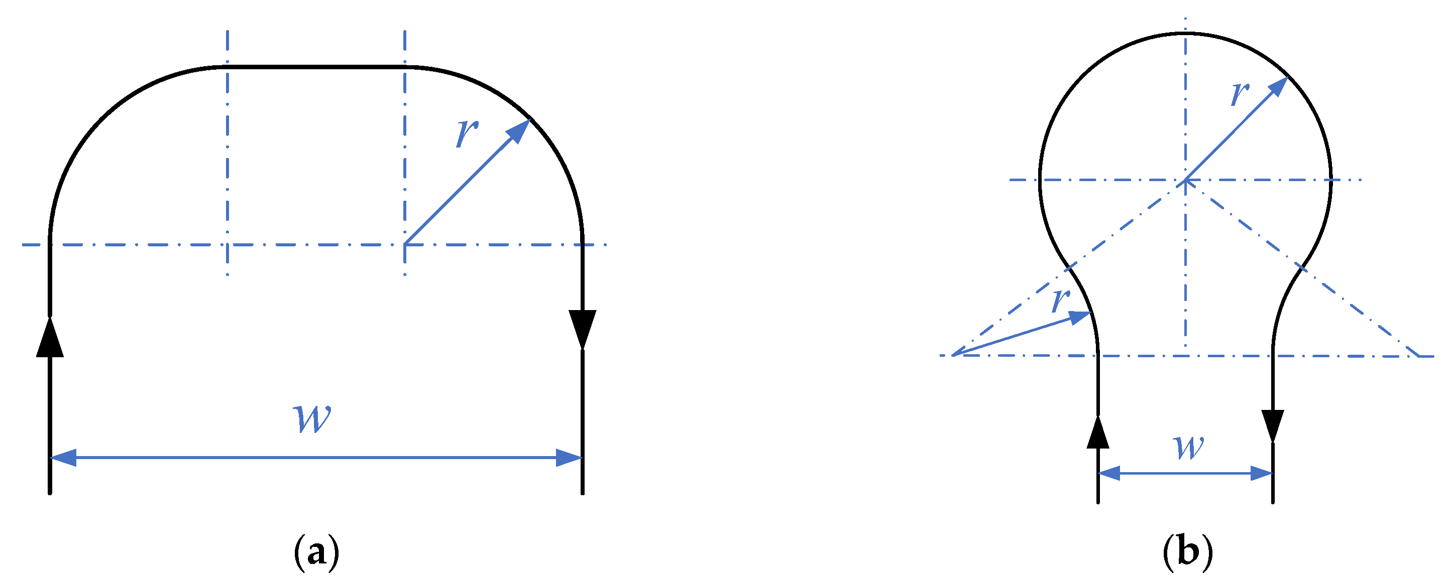
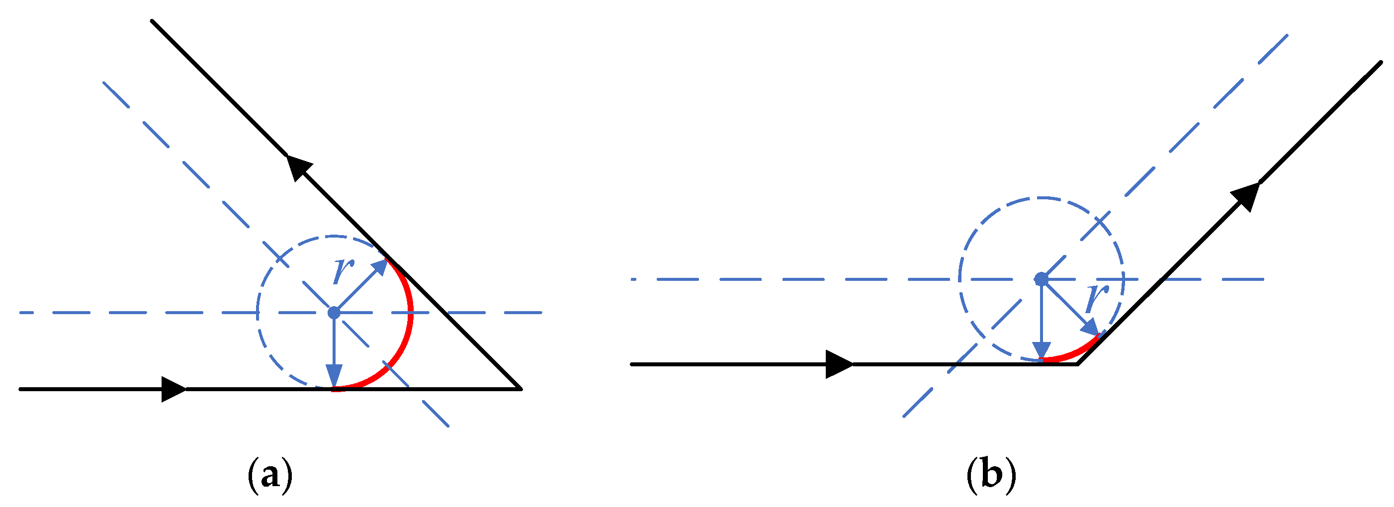
2.1.2. Tractor Turning Strategy

The working path of tractors is unique compared with the working path of passenger vehicles. In particular, the turning condition of tractors needs to be considered during the process of agricultural production. The turning path is used to connect two linear working paths. There are two kinds of linear working paths: one is the working path in the working area, in which the paths are parallel, and the other is the operation path in the head of the field, which has an intersecting relationship. If there are two straight working paths connected by a turning path and located in different plot areas, the two working paths intersect each other.
According to the connection relationship between working paths, two groups of different turning strategies are adopted in this paper. When the directions of the working paths are parallel, the tractor carries out a 180° steering motion at the head of the field. According to the relationship between the minimum turning radius r and the operating width w of the tractor, different steering modes at the head of the field are selected. As shown in Figure 2a, a U-turn is performed when w ≥ 2r. A Ω-turn is performed when w < 2r in Figure 2b.
When two working paths intersect, the tractor is steered less than 180° at the intersection near the two working paths at the head of the field. According to the angle of the two intersecting working paths, there are two types of turning shown in Figure 3: the acute angle and the obtuse angle. The algorithm for generating the two turning paths is the same, which translates the distance r from the intersection of the two working paths to the inside of the angle. The intersection point of the translated working paths is taken as the center of the circle, and the distance r is taken as the radius to make an arc, which is the desired turning path tangent to the two working paths.

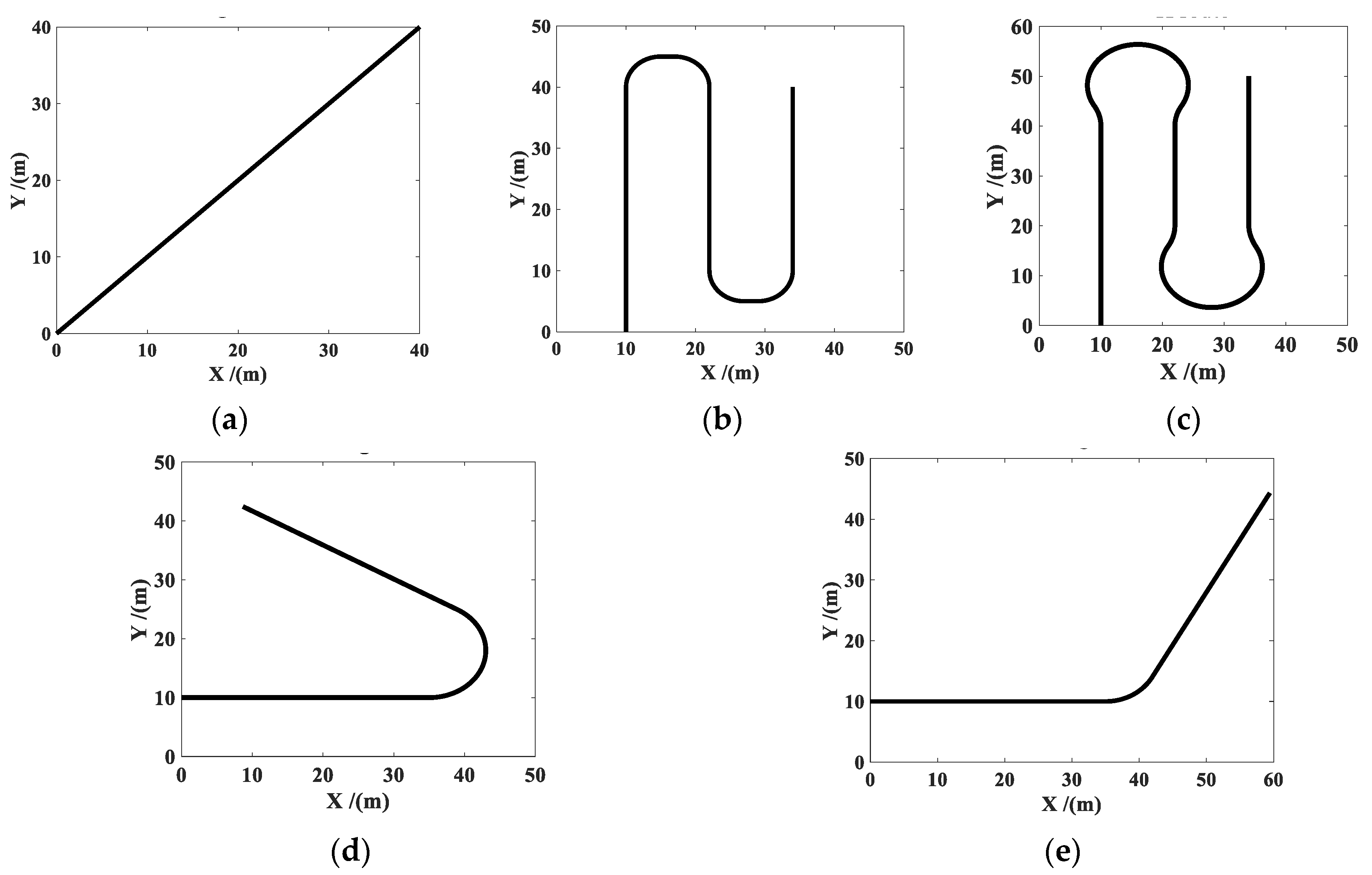
2.1.3. Tractor Working Route Development

According to the turning strategy above, several tractor working routes were used to test the path tracking controller designed in this study. Unlike previous studies that focused on how to plan the path to make tractors more efficient or complete specific tasks, this paper focuses on the development of path tracking control with predefined trajectories rather than relying on an advanced path planner. Every tractor working path consists of a series of points on a geodetic coordinate system. The coordinates (X, Y) of each point represent the actual field position. During the path tracking operation, the real-time position of the tractor on the geodetic coordinate system will be compared with these points. Then, the lateral error and trajectory states will be obtained.
Figure 4 shows the five routes used to test the path tracking controllers in this study. These routes were defined in MATLAB. They were straight, U, Ω, acute angle, and obtuse angle routes. It should be noted that the turning radius required for different turning methods was different. The values of the working width w and minimum turning radius r were determined by the size of the mounted agricultural implements. In this paper, w and r were set to 12 m and 5 m for U-turns, respectively. Additionally, w and r were set to 12 m and 8.2 m for Ω-turns, respectively.

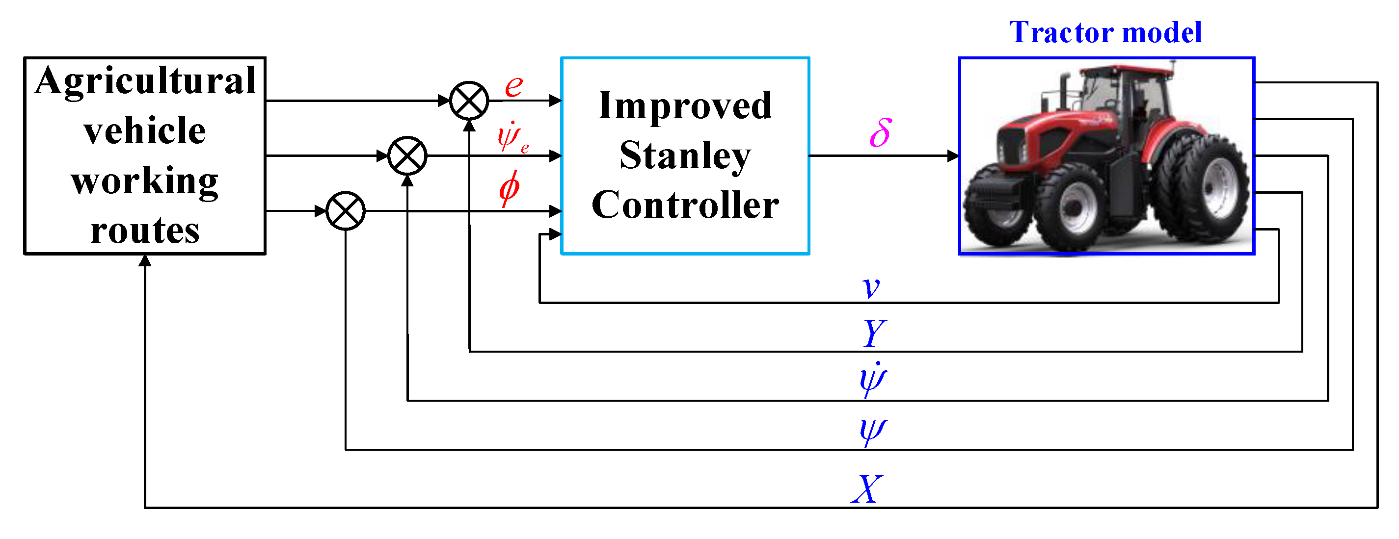
2.2. Path Tracking Control Strategies

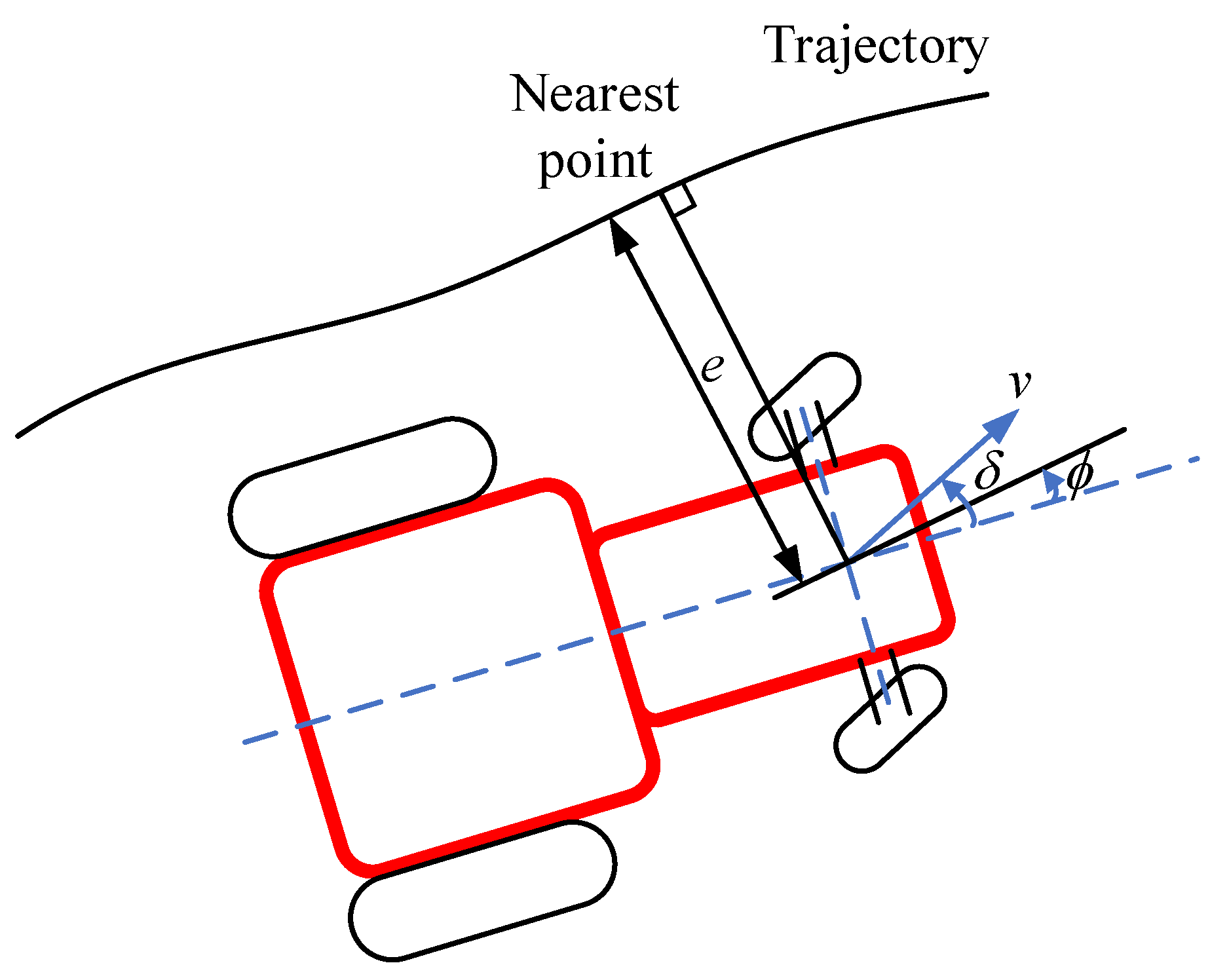
2.2.1. Stanley Controller (ST)

The original Stanley controller was used by the Stanford University team for the first time in the DARPA Grand Challenge 2005. It is a kind of nonlinear feedback control for lateral error, which makes the tractor follow the desired path by inputting the steering command of the front wheel. The relationship between the parameters of the Stanley controller is shown in Figure 5. The original steering command is shown in Equation (10) [17].
δ ( t ) = ϕ ( t ) + arctan ( k e ( t ) v ( t ) )
where ϕ ( t ) is the heading error between the tractor and path and ϕ ( t ) = ψ ( t ) ψ r o u t e ( t ) . e(t) is the lateral error between the center of the front axle and the nearest point on the trajectory. v(t) is the tractor speed, and k is an adjustable gain.

2.2.2. Extended Stanley Controller (EXT-ST)

An extended version of the Stanley controller was proposed by Hoffmann. The error between the instantaneous path and tractor yaw rate was added to the ST. The term ( ψ ˙ ( t ) ψ ˙ r o u t e ( t ) ) was associated with an adjustable gain k ψ to improve the motion stability of the tractor. Amer et al. added an adjustable gain k ϕ to the first part. The steering command is now composed of three parts, which are shown in Equation (11) [28] with the parameters defined in Figure 5.
δ ( t ) = k ϕ ϕ ( t ) + arctan ( k e ( t ) 1 + v ( t ) ) + k ψ ( ψ ˙ ( t ) ψ ˙ r o u t e ( t ) )

2.2.3. Improved Stanley Controller (IMP-ST)

This is the proposed controller for the tractor. The EXT-ST is improved by adding one additional part, the integral of the heading error, 0 t ϕ d t , which is associated with an adjusted gain, k2. The purpose of this improvement is to reduce the steady-state error of the steering system. At the same time, another gain k1 is added to the second part to increase the sensitivity of tuning the controller. Therefore, the complete steering command for the study now includes five adjustable parameters for its four parts, as presented in Equation (12). The control model is shown in Figure 6.
δ ( t ) = k ϕ ϕ ( t ) + k 1 arctan ( k e ( t ) 1 + v ( t ) ) + k 2 0 t ϕ d t + k ψ ( ψ ˙ ( t ) ψ ˙ r o u t e ( t ) )
Each part in Equation (12) plays an important role in agricultural automated tractor path tracking. The first part, with the heading error, is a proportional term, which observes the direction of the tractor. The second part, with the lateral error, represents the relative position between the tractor and desired path. The third part, with the heading error integral, will reduce the cumulative error in the steering process. The fourth part, with the yaw rate error, is a differential term, which will stabilize the yaw dynamics, especially for a low-speed off-road tractor.

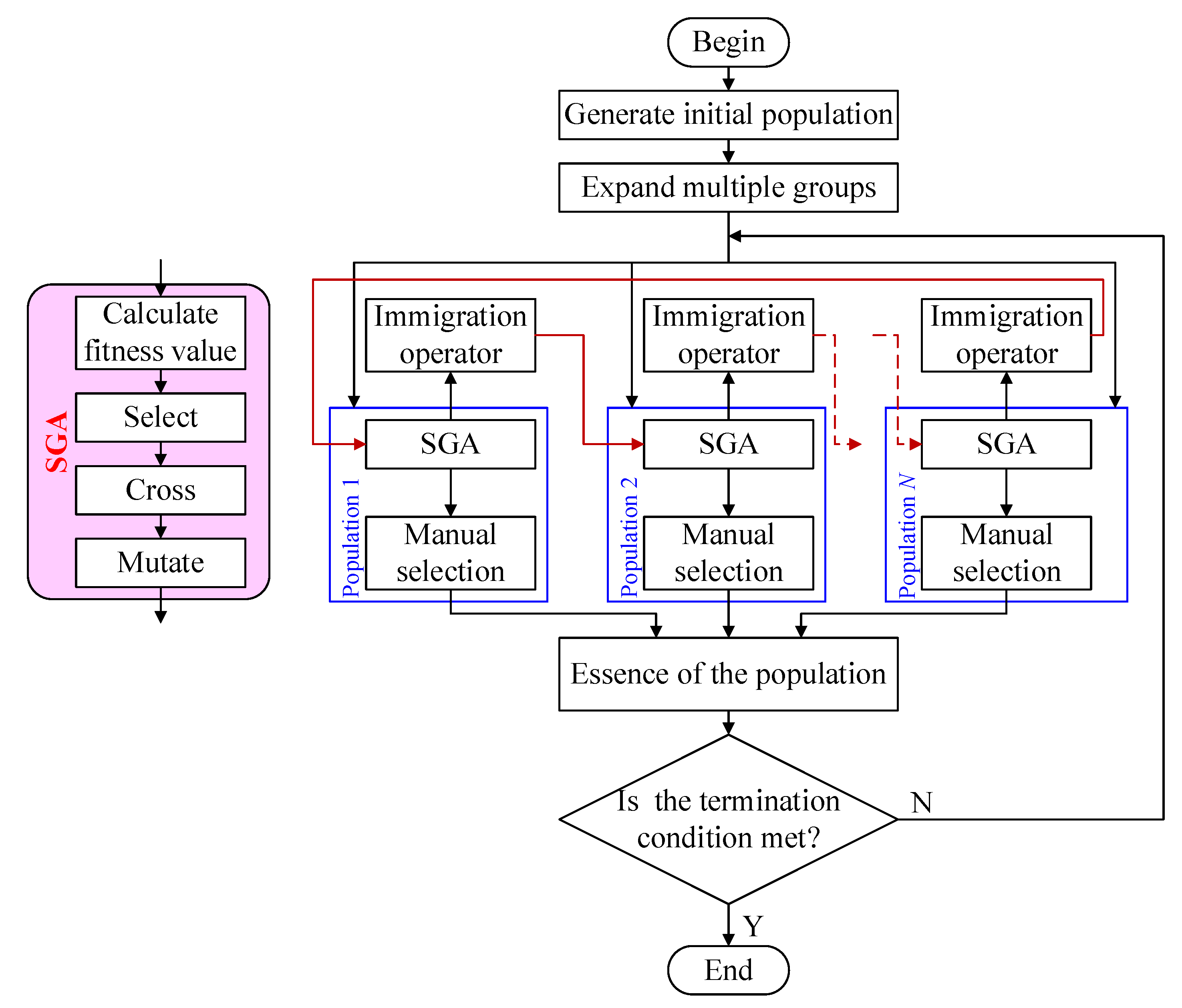
2.3. IMP-ST Parameter Tuning Using the MPGA

In this study, a series of controller parameters will be optimized to obtain better path tracking performance for methods, such as ST (k), EXT-ST ( k ϕ , k1, k and k ψ ), and IMP-ST ( k ϕ , k1, k, k2 and k ψ ). The multiple-population genetic algorithm will be used to look for the optimal parameters of each controller. In the field of control, the integral of time and absolute error (ITAE) is often used as an index to evaluate the performance of the control system. The system designed with ITAE index can consider the control speed and accuracy simultaneously, with small overshoot, good dynamic performance, and other advantages. The lateral error e is the best index for the tractor path tracking performance. Therefore, ITAE is chosen as the objective function F, as shown in Equation (13) [29]. When F reaches the minimum value, the tractor can achieve the best tracking performance.
F = 0 t t ( | e ( t ) | ) d t
The optimization procedure of the MPGA is shown in Figure 7. The MPGA introduces multiple populations and assigns different control parameters to optimize the search at the same time. The various populations are connected through the immigration operator to perform coevolution of multiple populations. The optimal individuals in each evolutionary generation of various groups are saved by manual selection operators and used as the basis for judging the convergence of the algorithm. When the optimization reaches the maximum number of iterations or the value of objective function F is less than the termination threshold, the optimization procedure is finished and optimal value of multiple parameters is output.
According to the MPGA optimization process, the values of k ϕ , k1, k, k2, and k ψ for the IMP-ST are determined for each tractor working route. The well-tuned parameters are shown in Table 2. Then, simulations are carried out for each tractor working route.

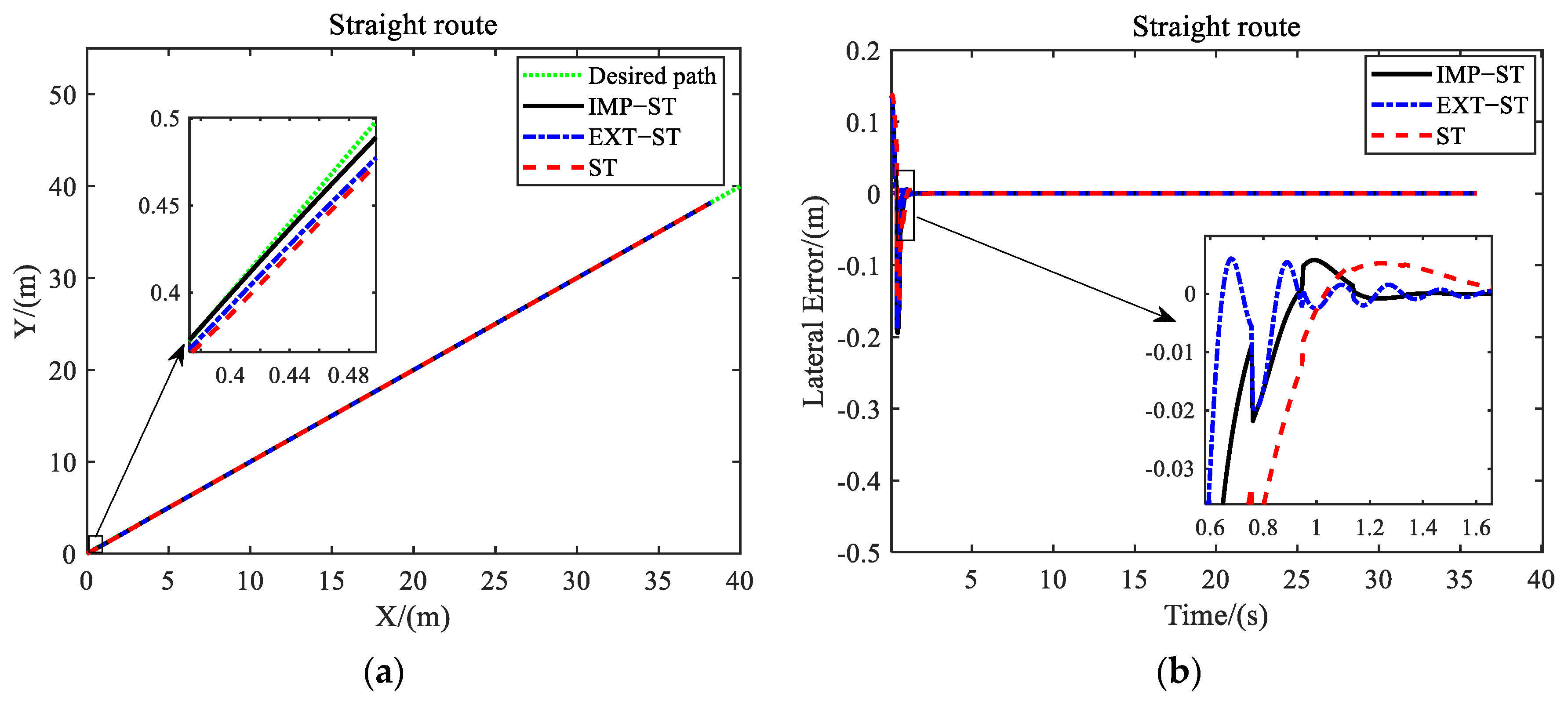
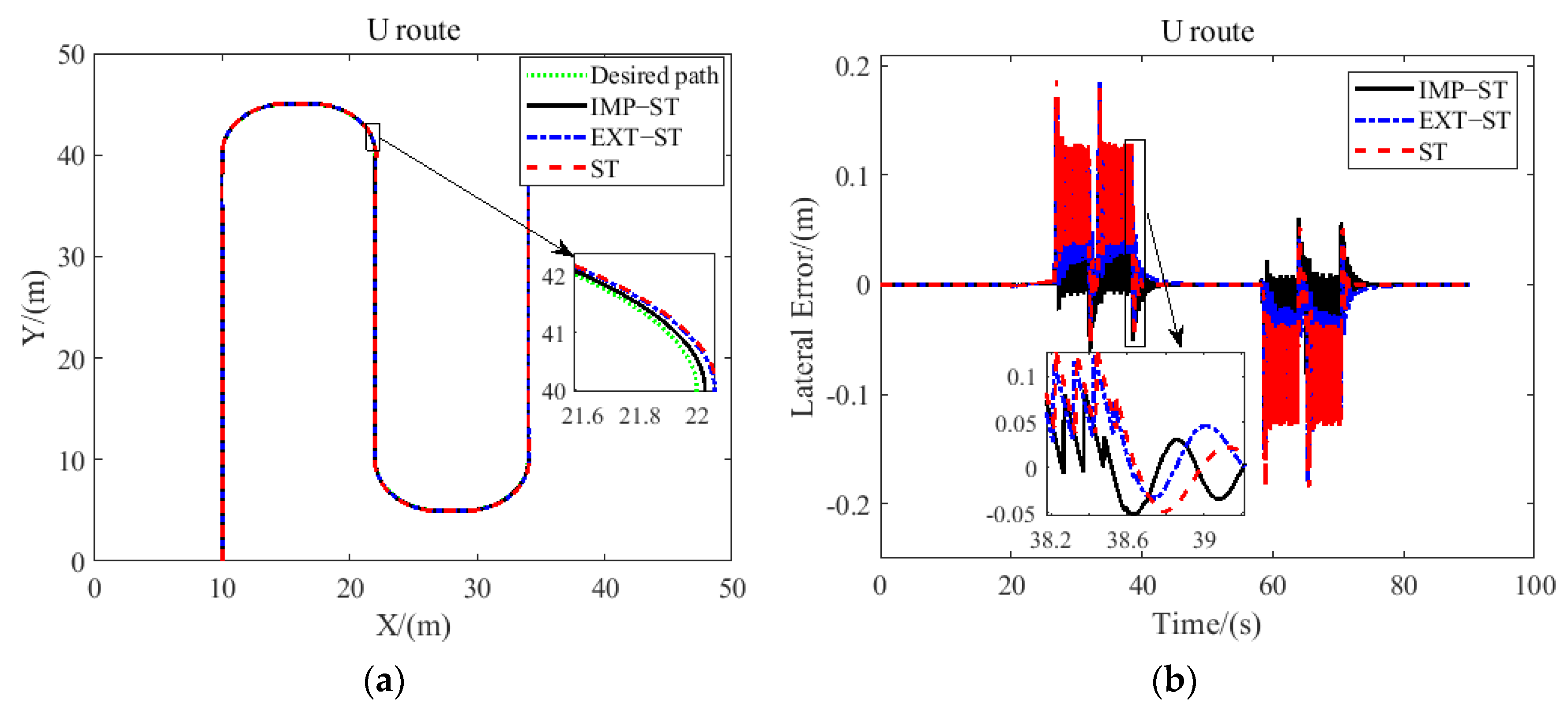
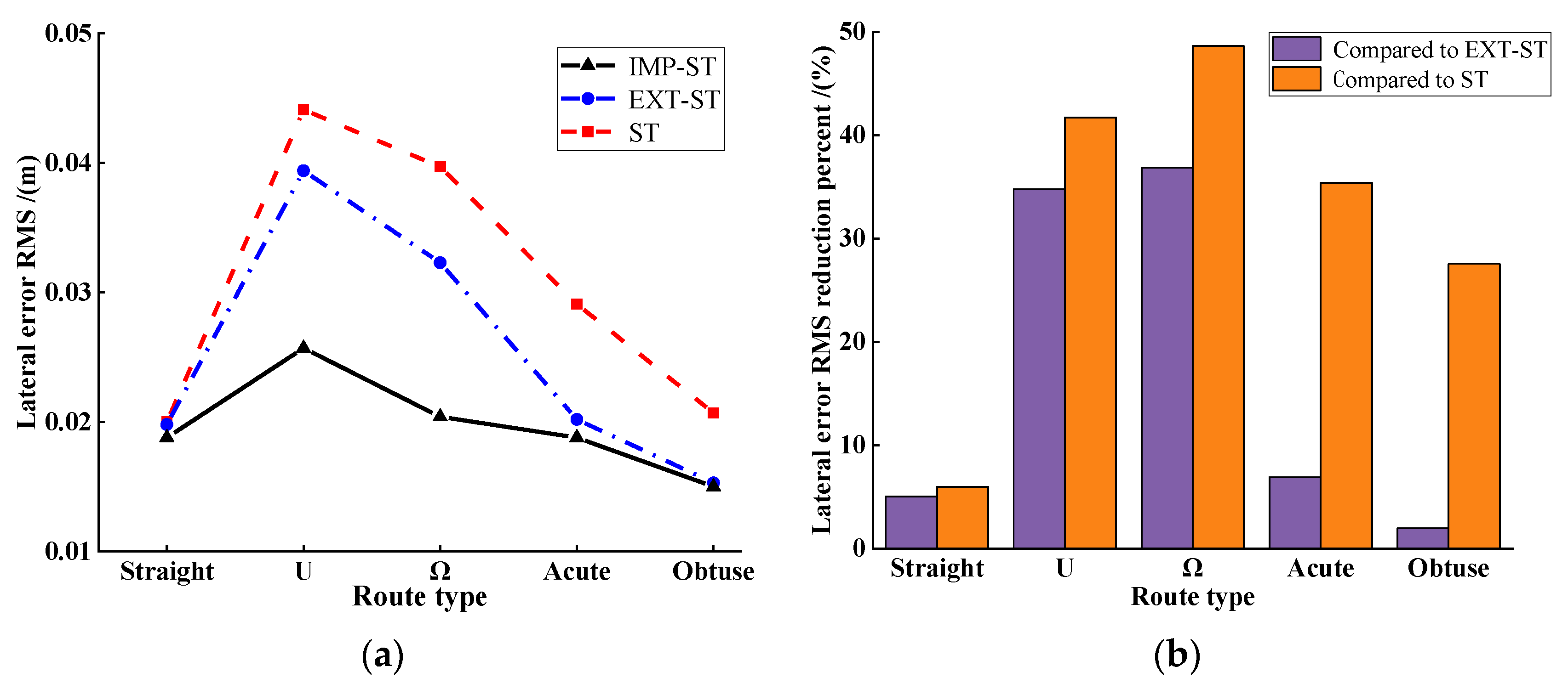
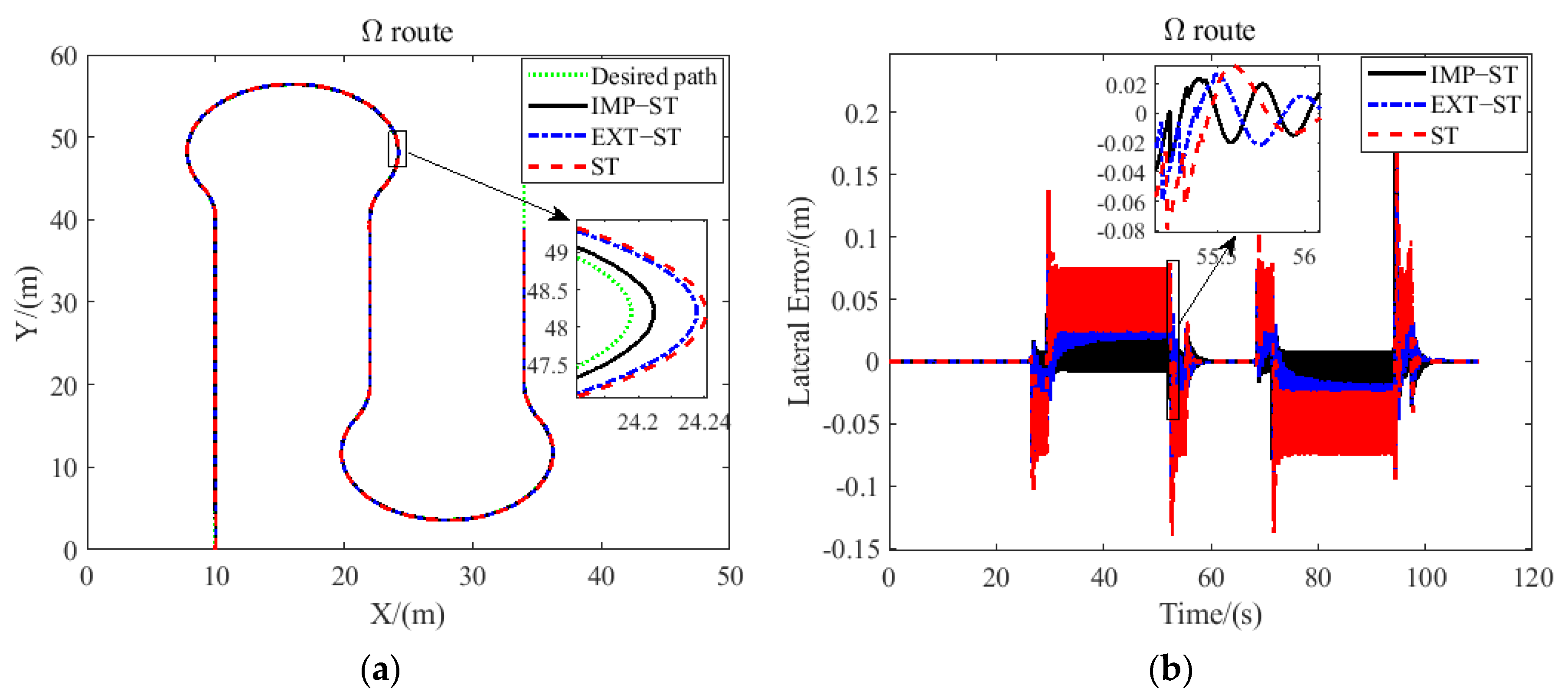
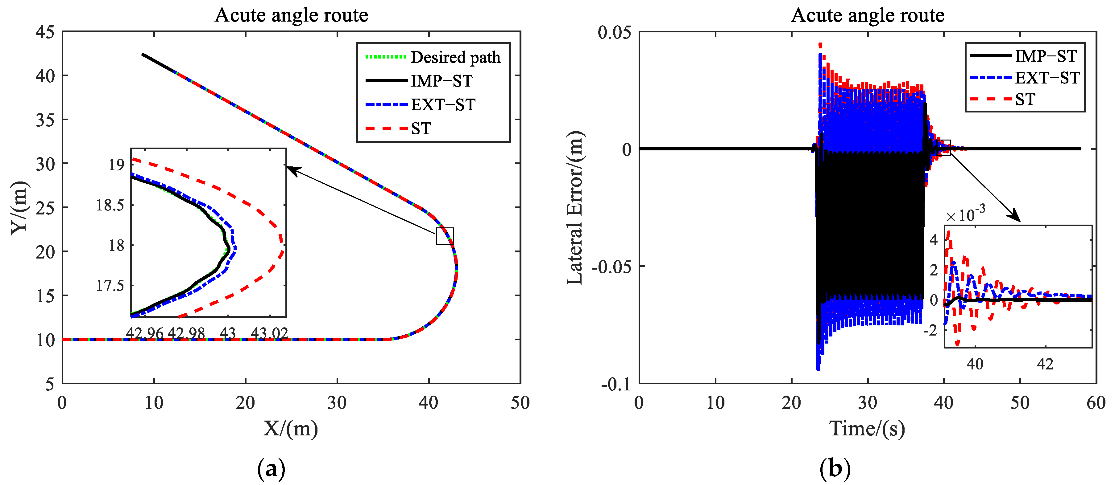
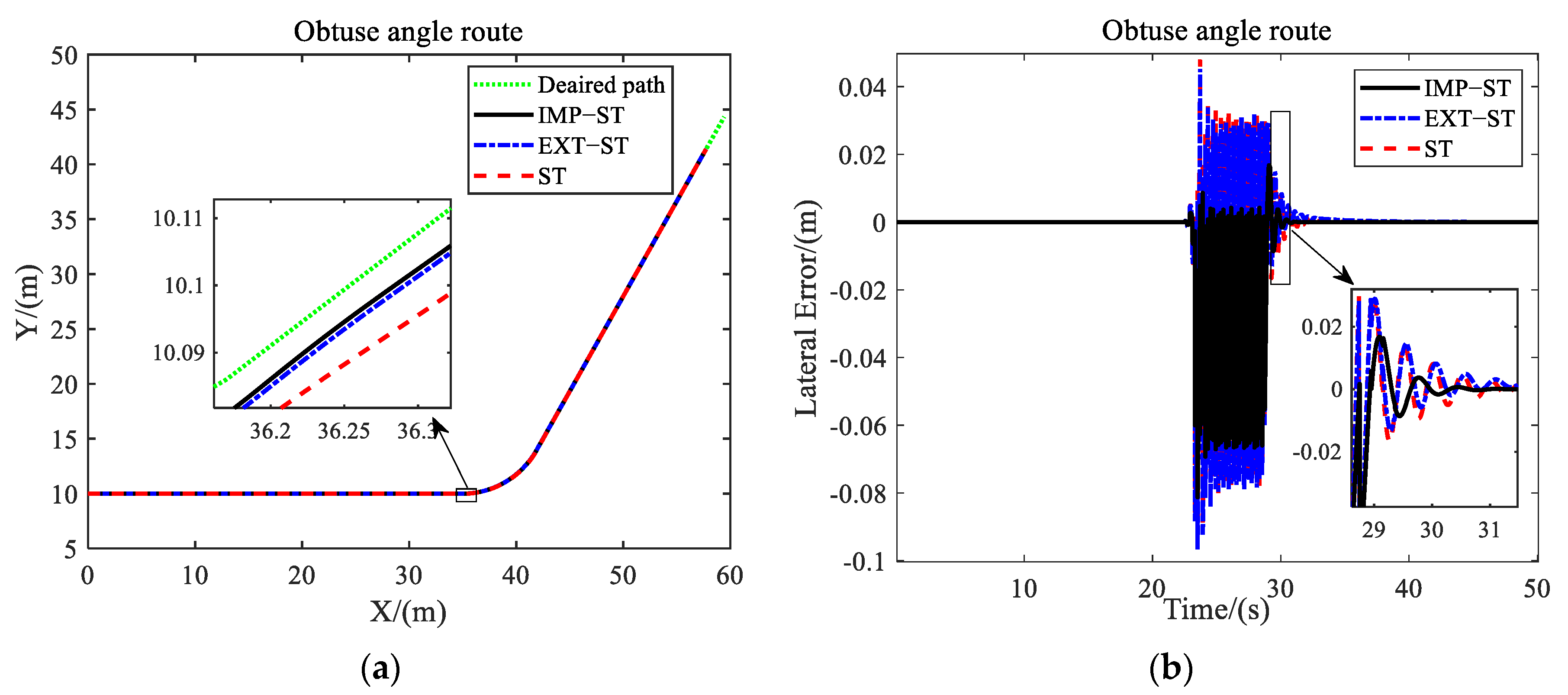
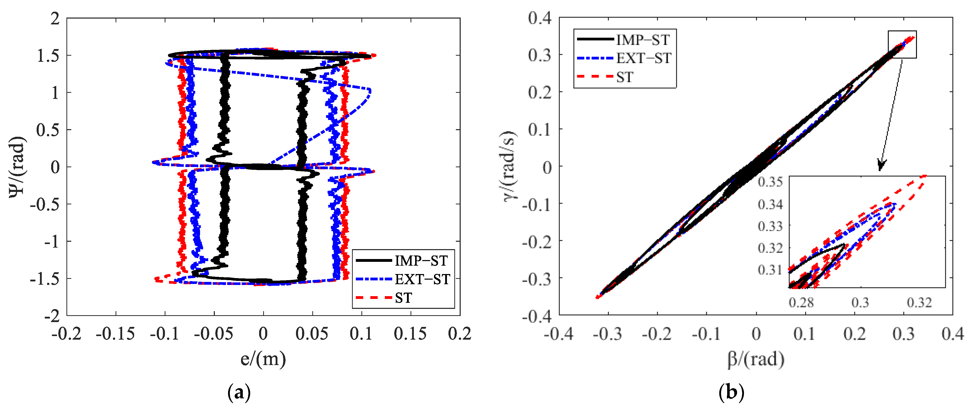
3. Results and Discussion

To verify the effectiveness of the proposed IMP-ST in tractor path tracking, simulations were carried out in MATLAB/SIMULINK. The path tracking performance of the IMP-ST was evaluated on the Dongfanghong LA3004 tractor model with a constant working speed of 1.5 m/s. The LA3004 tractor parameters are shown in Table 3. The controller performance was compared with ST, as shown in Equation (10), and EXT-ST, as shown in Equation (11). All the gains of the three controllers were optimized with the MPGA.
To evaluate the effectiveness of the IMP-ST, several responses were chosen. A comparison of the actual trajectory of the tractor and the expected path shows the tracking performance. At the same time, the lateral error of the path tracking is a specific numerical indicator for evaluating the tracking performance. The real-time dynamic responses of each route for each controller are shown in Figure 8, Figure 9, Figure 10, Figure 11 and Figure 12.
Figure 8 shows the tracking effect of the Stanley controller, extended Stanley controller, and improved Stanley controller on a straight route. Figure 8a shows that all controllers could make the tractor better track the straight working route, and the actual trajectory obtained by the improved Stanley controller was closer to the desired path. This can also be proven by the lateral deviation data in Figure 8b. The lateral error RMS value of the improved Stanley controller was 0.0188 m, which was 5.05% less than that of the extended Stanley controller and 6% less than that of the original Stanley controller. From Figure 8b, it can be seen that the lateral deviation of the tractor was large at the beginning. This was caused by the inconsistency between the direction of the straight route and the starting heading angle. However, it can be seen from the partially enlarged view that the IMP-ST could make the tractor track the working route faster and more stably.
Figure 9 shows the simulation results for the U route. In Figure 9a, compared with the other two controllers in the article, the IMP-ST proposed in this paper could steer the tractor to better track the operation route, especially when the tractor was turning at the edge of the field. As shown in Figure 9b, the lateral errors of the three controllers increased and fluctuated, but the fluctuation of the IMP-ST, ranging from −0.0792 m to 0.0861 m, was smaller. On average, the RMS value of the lateral error for the IMP-ST was 0.0257 m, which was 34.77% less than that of the EXT-ST and 41.72% less than that of the ST. The path tracking performance was significantly improved.
As shown in Figure 10, the results for the Ω route are similar to those for the U route. Figure 10a indicates that all three controllers could guide the tractor to follow the working route with no visible error. The effect of the improved Stanley controller was closer to the desired Ω route. This can be proven by the lateral error curves in Figure 10b. Due to the characteristics of the Ω route, the tractor needed to turn continuously when it was at the edge of a field, which caused the lateral deviation of the three controllers to increase. However, the IMP-ST obtained better lateral error than the EXT-ST and ST most of the time. The lateral error RMS value of the IMP-ST was 0.0204 m, 36.84% less than the 0.0323 recorded by the EXT-ST, and 48.61% less than the 0.0397 m recorded by the ST.
Figure 11 and Figure 12 show the simulation results for the acute and obtuse angle routes with the same layout as the previous results, respectively. Figure 11a and Figure 12a show that the path tracking performance of all controllers was good, and the proposed controller could guide the tractor closer to the two routes. This is also proven by the lateral error data shown in Figure 11b and Figure 12b. For the acute angle route, the lateral error RMS of the IMP-ST is 0.0188 m, which is 6.93% less than that of the EXT-ST and 35.40% less than that of the ST. For the obtuse angle route, the proposed controller recorded a lateral error RMS of 0.0150 m, which is 1.96% and 27.54% less than that of the extended Stanley controller and original Stanley controller.
From the overall path tracking performance of all three controllers for all working routes, one can conclude that all controllers could achieve good results in following the five predefined desired operation routes. However, the lateral error of the ST sometimes reached 0.2 m, especially when tracking the U and Ω routes. As shown in Figure 13a, the tracking performance of the EXT-ST and IMP-ST was obviously better than that of the ST. This is because their multiple parameters were tuned by the MPGA. The IMP-ST could achieve the smallest lateral error RMS compared to the other two controllers. Figure 13b indicates that the lateral error RMS of the IMP-ST ranged from 6% to 48.61% less than that of the ST. Moreover, for the two most common turning methods of tractor field work, i.e., the U and Ω routes, the improved Stanley controller had significant improvements of 34.77% and 36.84% less error than the EXT-ST.
The stability of tractor path tracking control is very important to normal field operations. The global asymptotic convergence of the Stanley controller has been proven in detail by Hoffmann et al. [17]. This paper takes the most commonly used U route for tractors as an example, and analyzes the stability of the improved Stanley controller through the phase plane of e-Ψ and β-γ, where β = y ˙ / x ˙ .
As shown in Figure 14a, the coordinate origin is the globally asymptotically stable equilibrium point of the three controllers. The phase plane convergence region of e-Ψ is bounded. If the e-Ψ phase plane area of the controller is large, it is easy to cross the phase plane saturation area, causing the control system to not converge. Comparing the three controllers, IMP-ST has the smallest e-Ψ phase plane area. The lateral error generated under the same heading angle is the smallest, and the phase plane is closer to the stable point, indicating that IMP-ST has the best control effect. As shown in Figure 14b, the β-γ phase plane of the three controllers can all converge. The coordinate origin is its stable point, and the motion state of the tractor is always kept in a stable area during the process of tracking the path. If the area of the β-γ phase plane is large, the possibility of tractor operation instability increases. It can be seen from the comparison that the maximum values of the sideslip angle of tractor’s mass center and the yaw rate are smaller than those of the other two controllers, and the β-γ phase plane area is closer to the stable point, so IMP-ST has the best control stability.

4. Conclusions

In this paper, a path tracking controller for tractors called the IMP-ST is proposed by improving the original Stanley controller. The ST, EXT-ST, and IMP-ST were optimized by the MPGA and evaluated on a two-wheel tractor dynamic model. Then, the three controllers were tested on five routes considering different working turning strategies of the tractor.
The simulation test results of all working routes showed that the lateral error RMS of the proposed controller (IMP-ST) had significant improvements of up to 36.84% and 48.61% compared to the EXT-ST and the original ST, respectively. The simulation verification indicated that the IMP-ST performed better in guiding the tractor to follow the planned working routes. The results of e-Ψ and β-γ phase plane of the three controllers indicate that the IMP-ST has the best control stability.
The proposed controller could satisfy the requirements of tractor working path tracking. In the future research, real tractor tests will be carried out to further verify the practical application effect of the method.

Author Contributions

Conceptualization, L.W.; methodology, L.W.; validation, L.W. and Z.Z. (Zhiqiang Zhai); investigation, L.W. and Z.Z. (Zhiqiang Zhai); resources, Z.Z. (Zhongxiang Zhu) and E.M.; writing—original draft preparation, L.W.; writing—review and editing, L.W. and Z.Z. (Zhiqiang Zhai); supervision, Z.Z. (Zhongxiang Zhu) and E.M.; project administration, Z.Z. (Zhongxiang Zhu) and E.M.; funding acquisition, Z.Z. (Zhongxiang Zhu) and E.M. All authors have read and agreed to the published version of the manuscript.

Funding

This work was supported by the National Natural Science Fund, grant number 52072407.

Institutional Review Board Statement

Not applicable.

Informed Consent Statement

Not applicable.

Data Availability Statement

All research data supporting this study are included in the manuscript.

Conflicts of Interest

The authors declare no conflict of interest.

References

  1. Zhu, Z.; Chen, J.; Yoshida, T.; Torisu, R.; Song, Z.; Mao, E. Path tracking control of autonomous agricultural mobile robots. J. Zhejiang Univ. Sci. A 2007, 8, 1596–1603. [Google Scholar] [CrossRef]
  2. Bell, T. Automatic tractor guidance using carrier-phase differential GPS. Comput. Electron. Agric. 2000, 25, 53–66. [Google Scholar] [CrossRef]
  3. Yin, X.; Du, J.; Noguchi, N.; Yang, T.; Jin, C. Development of autonomous navigation system for rice transplanter. Int. J. Agric. Biol. Eng. 2018, 11, 89–94. [Google Scholar] [CrossRef] [Green Version]
  4. Yin, X.; Noguchi, N.; Choi, J. Development of a target recognition and following system for a field robot. Comput. Electron. Agric. 2013, 98, 17–24. [Google Scholar] [CrossRef]
  5. Cho, S.I.; Chang, S.J.; Kim, Y.Y.; An, K.J. Development of a three-degrees-of-freedom robot for harvesting lettuce using machine vision and fuzzy logic control. Biosyst. Eng. 2002, 82, 143–149. [Google Scholar] [CrossRef]
  6. Meng, Q.; Qiu, R.; Zhang, M.; Liu, G.; Xiang, M. Navigation system of agricultural vehicle based on fuzzy logic controller with improved particle swarm optimization algorithm. Trans. Chin. Soc. Agric. Mach. 2015, 46, 29–36. [Google Scholar]
  7. Mercorelli, P. Using fuzzy PD controllers for soft motions in a car-like robot. Adv. Sci. Technol. Eng. Syst. J. 2018, 3, 380–390. [Google Scholar] [CrossRef] [Green Version]
  8. Jiao, J.; Chen, J.; Qiao, Y.; Wang, W.; Li, Z. Adaptive sliding mode control of trajectory tracking based on DC motor drive for agricultural tracked robot. Trans. Chin. Soc. Agric. Eng. 2018, 34, 64–70. [Google Scholar]
  9. Liu, Z.; Zheng, W.; Wang, N.; Lyu, Z.; Zhang, W. Trajectory tracking control of tractors based on disturbance test. Int. J. Agric. Biol. Eng. 2020, 13, 138–145. [Google Scholar]
  10. Liu, Z.; Lv, Z.; Zheng, W.; Zhang, W.; Cheng, X. Design of obstacle avoidance controller for agricultural tractor based on ROS. Int. J. Agric. Biol. Eng. 2019, 12, 58–65. [Google Scholar] [CrossRef]
  11. Vougioukas, S.; Blackmore, S.; Nielsen, J.; Fountas, S. A two-stage optimal motion planner for autonomous agricultural vehicles. Precis. Agric. 2006, 7, 361–377. [Google Scholar] [CrossRef]
  12. Chen, J.; Zhu, Z.; Torisu, R.; Taketa, J. On-tracking control of tractor running along curved paths. Trans. Chin. Soc. Agric. Eng. 2006, 22, 108–111. [Google Scholar]
  13. Li, G.; Wang, Y.; Guo, L.; Tong, J.; He, Y. Improved pure pursuit algorithm for rice transplanter path tracking. Trans. Chin. Soc. Agric. Mach. 2018, 49, 21–26. [Google Scholar]
  14. Tang, X.; Tao, J.; Li, Z.; Li, Y.; Liu, C. Fuzzy control optimization method for stability of path tracking system of automatic transplanter. Trans. Chin. Soc. Agric. Mach. 2018, 49, 29–34. [Google Scholar]
  15. Li, T.; Hu, J.; Gao, L.; Liu, X.; Bai, X. Agricultural machine path tracking method based on fuzzy adaptive pure pursuit model. Trans. Chin. Soc. Agric. Mach. 2013, 44, 205–210. [Google Scholar]
  16. Zakaria, M.; Zakaria, A.; Zamzuri, H.; Mazlan, S.A. Dynamic curvature steering control for autonomous vehicle: Performance analysis. IOP Conf. Ser. 2016, 114, 012149. [Google Scholar] [CrossRef] [Green Version]
  17. Hoffmann, G.M.; Tomlin, C.J.; Montemerlo, M.; Thrun, S. Autonomous automobile trajectory tracking for off-road driving: Controller design, experimental validation and racing. In Proceedings of the 2007 American Control Conference, New York, NY, USA, 11–13 July 2007. [Google Scholar]
  18. Viloria, A.; Zelaya, N.; Varela, N. Design and simulation of vehicle controllers through genetic algorithms. Procedia Comput. Sci. 2020, 175, 453–458. [Google Scholar] [CrossRef]
  19. Qian, Y.; Ou, G.; Maghareh, A.; Dyke, S.J. Parametric identification of a servo-hydraulic actuator for real-time hybrid simulation. Mech. Syst. Signal Process. 2014, 48, 260–273. [Google Scholar] [CrossRef]
  20. Receveur, J.; Victor, S.; Melchior, P. Robust longitudinal motion planning using vehicle model inversion. IFAC-PapersOnLine 2019, 52, 103–108. [Google Scholar] [CrossRef]
  21. Shen, C.; Song, R.; Li, J.; Zhang, X.; Tang, J.; Shi, Y.; Liu, J.; Cao, H. Temperature drift modeling of MEMS gyroscope based on genetic-Elman neural network. Mech. Syst. Signal Proc. 2016, 72–73, 897–905. [Google Scholar]
  22. Feng, H.; Yin, C.; Weng, W.; Ma, W.; Zhou, J. Robotic excavator trajectory control using an improved GA based PID controller. Mech. Syst. Signal Proc. 2018, 105, 153–168. [Google Scholar] [CrossRef]
  23. Meng, Y.; Gan, X.; Wang, Y.; Gu, Q. LQR-GA controller for articulated dump truck path tracking system. J. Shanghai Jiaotong Univ. 2019, 24, 78–85. [Google Scholar] [CrossRef]
  24. Lu, K.; An, X.; Li, J.; He, H. Efficient deep network for vision-based object detection in robotic applications. Neurocomputing 2017, 245, 31–45. [Google Scholar] [CrossRef]
  25. Reina, D.G.; Tawfik, H.M.; Toral, S.L. Multi-subpopulation evolutionary algorithms for coverage deployment of UAV-networks. Ad Hoc Netw. 2018, 68, 16–32. [Google Scholar] [CrossRef]
  26. Yu, Z. Vehicle Theory, 5th ed.; China Machine Press: Beijing, China, 1990; pp. 144–146. [Google Scholar]
  27. Joop, P.P. Essentials of Vehicle Dynamics, 5th ed.; Elsevier: Amsterdam, The Netherlands, 2015; pp. 131–138. [Google Scholar]
  28. Amer, N.H.; Zamzuri, H.; Hudha, K.; Aparow, V.R.; Kadir, Z.A. Path tracking controller of an autonomous armoured vehicle using modified Stanley controller optimized with particle swarm optimization. J. Braz. Soc. Mech. Sci. Eng. 2018, 40, 104. [Google Scholar] [CrossRef]
  29. Rao, C.S.; Santosh, S.; Ram, D. Tuning optimal PID controllers for open loop unstable first order plus time delay systems by minimizing ITAE criterion. IFAC-PapersOnLine 2020, 53, 123–128. [Google Scholar] [CrossRef]
Figure 1. The 2-wheel tractor dynamic model.
Actuators 11 00022 g001
Figure 2. Turning strategy with parallel working paths. (a) U-turn; (b) Ω-turn.
Actuators 11 00022 g002
Figure 3. Turning strategy with intersecting working paths. (a) Acute angle; (b) obtuse angle.
Actuators 11 00022 g003
Figure 4. Turning strategy with intersecting working paths. (a) straight route; (b) U route; (c) Ω route; (d) acute angle route; (e) obtuse angle route.
Actuators 11 00022 g004
Figure 5. Parameters of the Stanley controller.
Actuators 11 00022 g005
Figure 6. Control model of the IMP-ST.
Actuators 11 00022 g006
Figure 7. The optimization procedure of the MPGA.
Actuators 11 00022 g007
Figure 8. Path tracking performance comparison of three controllers for a straight route. (a) trajectory; (b) lateral error.
Actuators 11 00022 g008
Figure 9. Path tracking performance comparison of three controllers for the U route. (a) trajectory; (b) lateral error.
Actuators 11 00022 g009
Figure 10. Path tracking performance comparison of three controllers for the Ω route. (a) trajectory; (b) lateral error.
Actuators 11 00022 g010
Figure 11. Path tracking performance comparison of three controllers for the acute angle route. (a) trajectory; (b) lateral error.
Actuators 11 00022 g011
Figure 12. Path tracking performance comparison of three controllers for the obtuse angle route. (a) trajectory; (b) lateral error.
Actuators 11 00022 g012
Figure 13. Path tracking performance comparison and analysis. (a) lateral error RMS; (b) lateral error RMS reduction percent.
Actuators 11 00022 g013
Figure 14. Path tracking stability comparison and analysis. (a) e-Ψ phase plane; (b) β-γ phase plane.
Actuators 11 00022 g014
Table 1. Nomenclature of the 2-wheel tractor dynamic model.
SymbolSymbol Name
δffront wheel angle
vfmidpoint speed of front axle
vxflongitudinal speed of front wheel
vyflateral speed of front wheel
αffront tire sideslip angle
Fxffront wheel longitudinal force
Fyffront wheel lateral force
Fxrrear wheel longitudinal force
Fyrrear wheel lateral force
lfdistance between front axle and center of tractor mass
lrdistance between rear axle and center of tractor mass
ψ tractor yaw angle
x ˙ tractor longitudinal speed
y ˙ tractor lateral speed
γ tractor yaw rate
Table 2. The well-tuned parameters.
STEXT-STIMP-ST
kkϕkkψkϕk1kk2kψ
Straight6.09571.869819.99981.63294.618515.76786.18120.07627.3743
U2010.653219.9999−0.1335−19.0676−3.8958−16.57420.01470.3219
2020200.063−19.999317.28295.0357−0.0121.075
Acute angle202020−0.10698.6726−5.9782−5.8169−0.0225−0.0891
Obtuse angle2016.843519.9999−0.10065.8624−3.0214−10.64470.0196−0.0687
Table 3. The tractor (LA3004) parameters.
SymbolUnitValue
masskg10,017
Izkg·m215,000
lengthm6.28
widthm2.49
heightm3.4
wheelbasem3
lfm1.84
lrm1.44
Publisher’s Note: MDPI stays neutral with regard to jurisdictional claims in published maps and institutional affiliations.

