Article

Development of a Mechatronic System for the Mirror Therapy

Department of Mechanical, Chemical and Materials Engineering, University of Cagliari, Via Marengo, 2, 09123 Cagliari, Italy
*
Author to whom correspondence should be addressed.
These authors contributed equally to this work.
Actuators 2022, 11(1), 14; https://doi.org/10.3390/act11010014
Submission received: 1 December 2021 / Revised: 31 December 2021 / Accepted: 3 January 2022 / Published: 5 January 2022
(This article belongs to the Special Issue Dynamics and Control of Robot Manipulators)

Abstract

:
This paper fits into the field of research concerning robotic systems for rehabilitation. Robotic systems are going to be increasingly used to assist fragile persons and to perform rehabilitation tasks for persons affected by motion injuries. Among the recovery therapies, the mirror therapy was shown to be effective for the functional recovery of an arm after stroke. In this paper we present a master/slave robotic device based on the mirror therapy paradigm for wrist rehabilitation. The device is designed to orient the affected wrist in real time according to the imposed motion of the healthy wrist. The paper shows the kinematic analysis of the system, the numerical simulations, an experimental mechatronic set-up, and a built 3D-printed prototype.

1. Introduction

Limb rehabilitation using robotic devices is an innovative form of rehabilitation based on interactions between the patient and the device. These systems augment the rehabilitation outcomes in neurologic disorders, such as stroke and multiple sclerosis. Robotic therapy provides high-intensity and repeated training and it can be used as an effective complement to standard rehabilitation from the beginning of a therapy [1,2]. The results show in all cases that patients who received the robotic therapy in addition to conventional therapy have greater reductions in motor impairment [3,4,5,6]. The robotic rehabilitation systems can be classified according to the design, depending on whether it operates as end-effector or as an exoskeleton. Another classification is between proximal and distal robots. Proximal robots are used to move the shoulder joint and the elbow joint; distal robots are rehabilitation robots for fine motor skills. They are used to train the hand and the fingers. Finally, rehabilitation robots can be classified as unilateral and bilateral. Unilateral devices use only the paralyzed limb for rehabilitation tasks, whereas bilateral robots use both limbs, the paralyzed and the healthy one [7].
There are numerous successful implementations of robotic rehabilitation devices. One of the first examples was the MIT-MANUS, which had a major impact on neuro-rehabilitation. The MIT-MANUS can move and guide the upper limb and record the trajectory, the velocity and the force of movement [8], indeed, this application can be classified as proximal and unilateral. A similar concept was described in [9]. An approach for robotic rehabilitation was used with MIME (Mirror Image Movement Enabler) [10], using an industrial robot to train the arm. A pneumatic system is the RUPERT (Robotic Upper Extremity Repetitive Therapy), which is an exoskeletal type. It consists of four pneumatic muscles, [11]. MACARM (Multi-Axis Cartesian-based Arm Rehabilitation Machine) is a planar cable-driven system designed for the rehabilitation of the upper limb [12]. The use of this kind of technology was further used in [13,14], although for correct operations, several issues for the design and modeling should be considered [15,16,17]. NeReBot and then MariBot are cable-driven systems with proximal, unilateral end-effector devices [18,19]. A cable-driven robot was proposed for mirror therapy in [20] and a real-time two-axis mirror robot system was developed for functional recovery of hemiplegic arms in [21].
In this paper, we present the design, analysis and experimental set-up of a system based on the mirror therapy concept suited to wrist rehabilitation. Mirror therapy is an effective occupational therapy for functional recovery of a hemiplegic arm after stroke [22,23,24]. It can facilitate brain neuroplasticity through activation of the sensorimotor cortex. The standard approach uses a simple mirror and the individual sits orthogonal to the mirror. The affected limb is positioned behind the mirror, so that it blocks the view and shows the non-paralyzed limb. Watching the mirror, the motion of the master limb is ideally projected to the paralyzed limb (the slave). The mirroring creates the illusion where it looks like the paralyzed limb would do the same movement as the non-paralyzed one. With this visual illusion, damaged nerve connections in the brain should be stimulated to make reconnections [25]. Moreover, mirror therapy has been used for chronic pain [26,27], and, as it was introduced by Vilayanur S. Ramachandran [28], as a therapy against phantom pain.
In our implementation, the system is designed to orient the affected wrist (slave) in real time according to the imposed motion of the healthy wrist (master).
The rest of the paper is organized as follows: In Section 2 a description of the system is provided, Section 3 presents the kinematic analysis of the mechanisms, Section 4 shows the numerical results obtained from the simulations whilst in Section 5 we describe the experimental set-up. Finally, in Section 6 the conclusions are drawn.

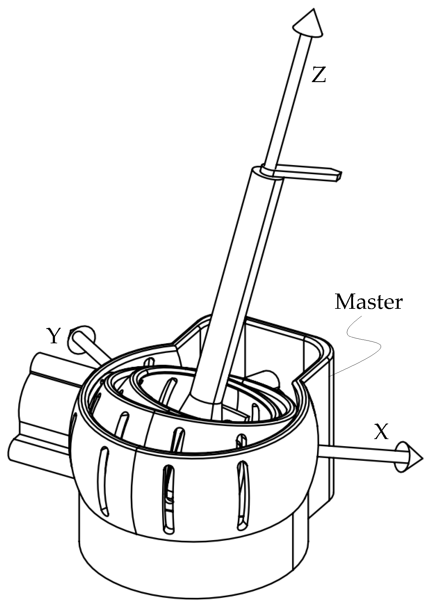
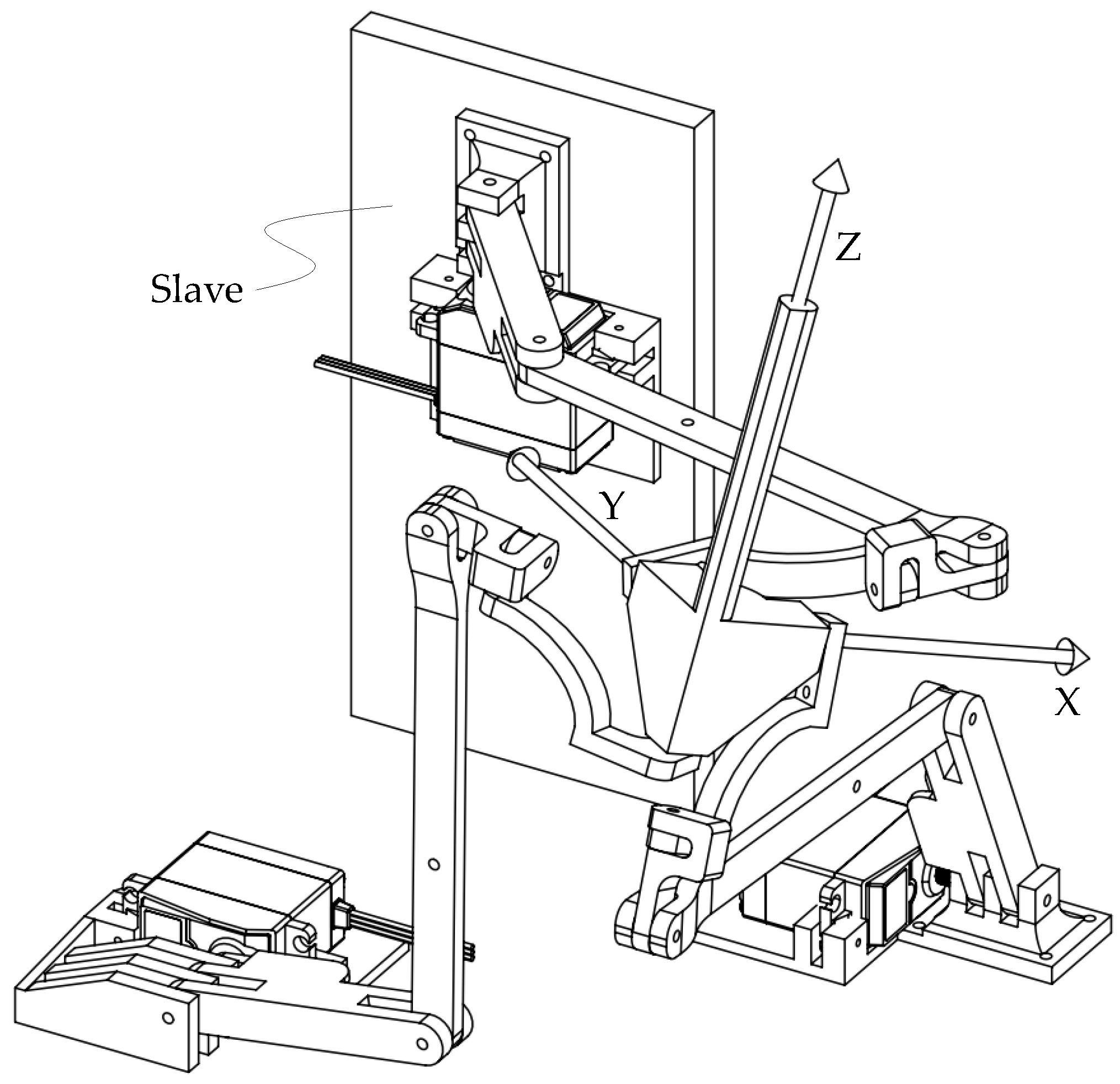
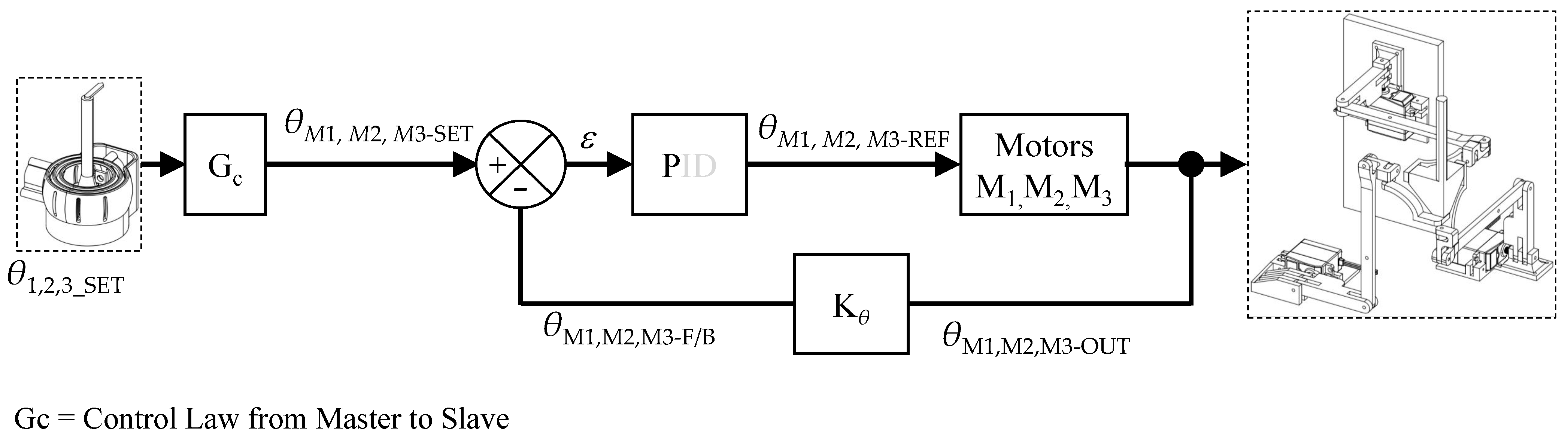
2. Description of the System
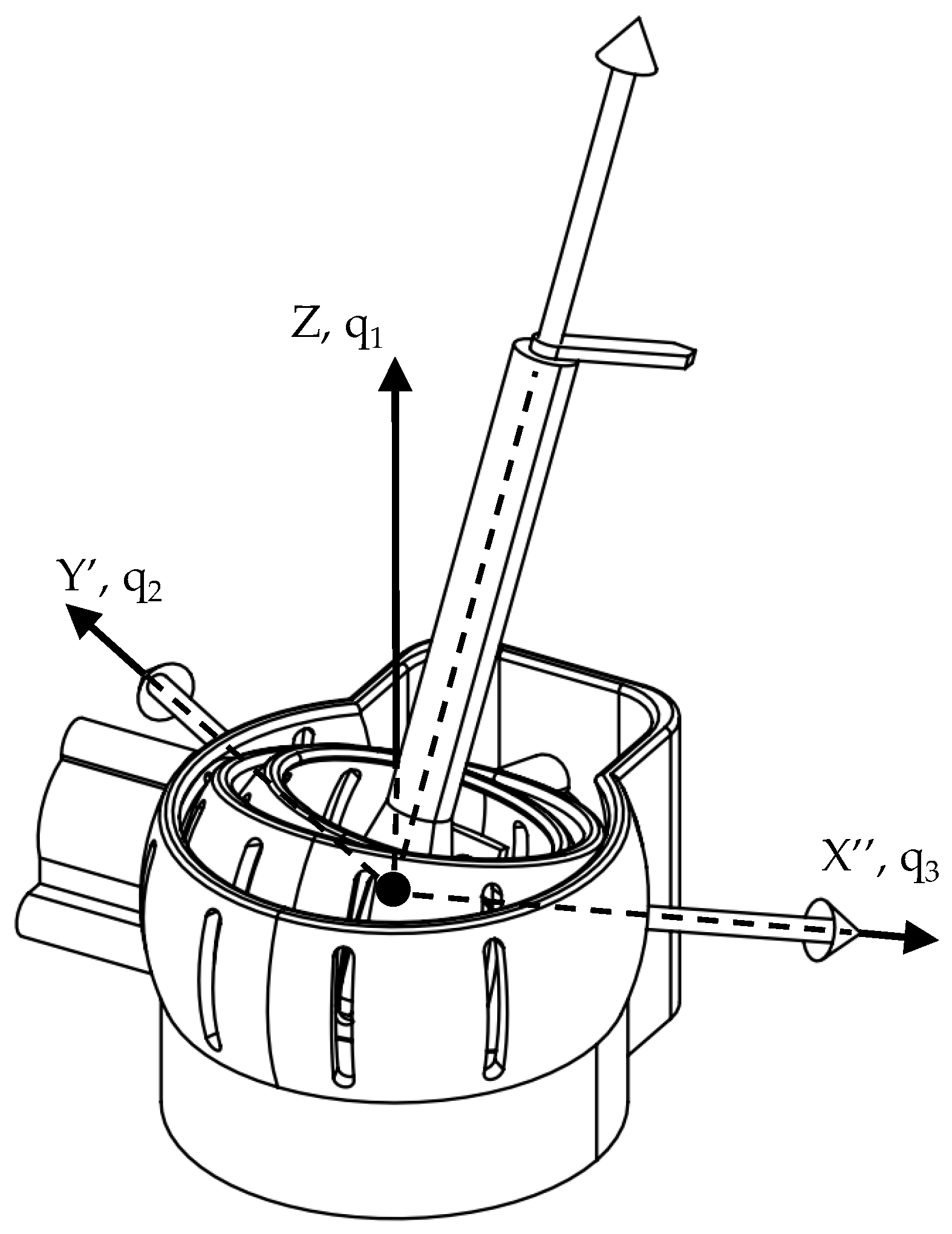
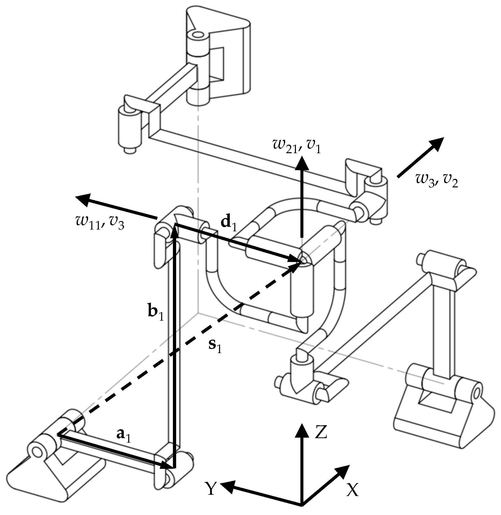
The system is basically composed of two units, which are called master and slave, the master is interacting with the full functional upper limb, while the slave is devoted to the affected upper limb. The two mechanisms are different because they must have different functions. The master is designed and built as a three-axis gimbal. Figure 1 illustrates a view of the master. In a typical gimbal, there are two or three motors on the system with the aim to prevent or eliminate vibration or locate an end-effector in space [29,30]. The basic aim of a gimbal is to minimize the vibration in video recording devices, and creating a reverse motion in the opposite direction of the vibration. The reverse motion can be provided by using an inertial measuring unit (IMU) sensor, which is placed on the camera and detects the camera movements and reports the motion to three servomotors positioned in line with the camera lens. The IMU detects the relative pose of the camera according to the ground, and based on the predetermined optimum position, the deviation between the two is evaluated. Then, an electronic board receives and processes data from the IMU and then transmits the information to the servomotors of the gimbal, which provides smooth motion. Thus, the servomotors that produce the opposite movement of the camera allows obtaining a smooth image. We have used the same concept to design a gimbal for tracking the orientation of the full-functional upper limb. Instead of using the IMU, we have chosen encoders. The motivation is that the orientation of the hand must be tracked and measured, instead of its angular velocity and acceleration. Nevertheless, in future applications, we may consider the use of an IMU.
The slave is a spherical parallel mechanism [31,32]. Figure 2 illustrates a view of the slave. It consists of a fixed base and an end-effector, hereafter referred to as the joystick, connected to each other by three identical limbs, each with an RRUR kinematic chain (R stands for revolving joint, U stands for universal joint formed by two concurrent R joints, P stands for prismatic joint and S stands for spherical joint) [33]. In each limb the first three R joints have parallel axes forming a planar chain whilst the last two R joints are perpendicular to each other, intersecting in the center of rotation of the joystick. Only the R pairs connected to the frame are actuated. The motors torques allow the joystick to fully rotate about the center of rotation. The mechanism is decoupled and not-overconstrained.
In literature, there are numerous applications of the parallel mechanisms for rehabilitation tasks. Some ankle rehabilitation devices proposed have the 3-RRR [34], 2-RRR/UPRR [35], 2-UPS/RRR [36], 3-RRS [37] geometries and to fit more closely the ankle motion Zhang et al. exploited a more complex parallel geometry [38]. There are, also, parallel geometries exploited for upper limb, wrist rehabilitation devices as those proposed in [39,40].
In summary, the choice of the three-axis gimbal geometry is motivated by its simplicity. In fact, the simple kinematics allows us to obtain the joystick orientation straight from the encoders measurements. Additionally, there are no strict requirements in terms of dynamics as the motion is imposed by the healthy hand. Conversely, the slave mechanism must reduce the inertial effects as the affected hand follows the driven motion and it has to be accurate and repeatable in posing the joystick. For these reasons, the parallel architecture appeared to be appropriate as it presents light moving links with the motors fixed at the base. Furthermore, the closed chain geometry may allow us to have high accuracy and repeatability.

3. Kinematics

The master mechanism is moved by the patient healthy arm with the rotations measured by encoders. A forward position kinematics allows us to obtain the orientation of the joystick. Because of the numerical efficiency, a quaternion parametrization was used such that the rotation of the joystick can be expressed as the compositional rotation of the intrinsic Tait–Bryan angles, ψ , θ , ϕ :
q = q 3 q 2 q 1 ,
with
q 1 = cos ( ψ 2 ) + sin ( ψ 2 ) k , yaw q 2 = cos ( θ 2 ) + sin ( θ 2 ) j , pitch q 3 = cos ( ϕ 2 ) + sin ( ϕ 2 ) i . roll
Equation (1) indicates a rotation q 1 followed by rotation q 2 and followed by rotation q 3 as shown in Figure 3.
The slave mechanism drives the patient affected arm by three servo-motors. An inverse kinematics is needed to obtain the motors rotations from the orientation of the joystick q.
With reference to the Figure 4, the equations required to solve the inverse position kinematics are obtained considering the ith. of the 3-RRUR mechanism:
a i + b i + d i = s i ,
v i T w i = 0 .
The solving procedure is: (a) to obtain the orientation λ i of d i = d w i by solving Equation (3), (b) to obtain the motors rotations by solving Equation (2).
Under the rotation q = q 0 + q 1 i + q 2 j + q 3 k from the joystick of the master mechanism, w i are obtained as (Figure 5):
w 1 = e 1 j e 1 * , w 2 = e 2 k e 2 * , w 3 = e 3 i e 3 * ,
where e i * is the ith. conjugate quaternion and
e 1 = e 01 + e 11 i , e 2 = e 02 + e 22 j , e 3 = e 03 + e 33 k .
e 1 , e 2 , e 3 are the Euler parameter quaternions that represent the unknown rotations λ i of w i around the first three axes of each limb. On the other hand the axes v i connected to the joystick are rotated by q.
v 1 = q k q * , v 2 = q i q * , v 3 = q j q * .
Equation (3) leads to:
( 2 e 11 2 1 ) ( 2 q 0 q 1 2 q 2 q 3 ) 2 e 01 e 11 ( 2 q 1 2 + 2 q 2 2 1 ) = 0 , ( 2 e 22 2 1 ) ( 2 q 0 q 2 2 q 1 q 3 ) 2 e 02 e 22 ( 2 q 2 2 + 2 q 3 2 1 ) = 0 , ( 2 e 33 2 1 ) ( 2 q 0 q 3 2 q 1 q 2 ) 2 e 03 e 33 ( 2 q 1 2 + 2 q 3 2 1 ) = 0 .
Equation (4) with the Euler parameters normalized equations, namely e 0 i 2 + e i i 2 = 1 , form two equations with two unknowns for each limb that can be easily solved. The sought angles λ i are then obtained as: λ i = 2 a t a n ( e i i / e 0 i ) . It is worth noting that geometrically the solutions are obtained as intersection points of a conics and a circle in the Euler parameters plane { e 0 i , e i i } . An example is shown in Figure 6. It may be noted that, because of the symmetry of the solutions, a couple of points provides the same angle leading to only two distinct solutions.
The rest of the solution procedure consists of solving the inverse kinematics of a three-link planar manipulator, namely Equation (2), with λ i = i = 1 3 θ 1 i as known values:
a c θ 1 i + b c ( θ 1 i + θ 2 i ) = p y i d c λ i , a s θ 1 i + b s ( θ 1 i + θ 2 i ) = p z i d s λ i ,
with ( p y i , p z i ) coordinates of the center of rotation expressed in the reference system of the limb. The procedure is well-known [41] and for this reason it is not reported here in the detail. First, θ 2 i is obtained by squaring and summing up Equation (5) to have the multiple solutions corresponding to the elbow-up or the elbow-down, then s θ 1 i and c θ 1 i can be obtained as the solution of a linear system.

Range of Motion

In the light of the application under study, it is required to know the range of motion of each input link of the slave mechanism.
In doing that the planar three-link model of the ith. limb is considered. According to Figure 7, the maximum Euler angle β and the limiting values of the input angle θ 1 i can be obtained geometrically. Firstly, the limit of the counterclockwise input rotation θ 1 i u is considered. θ 1 i u is reached when the first two links of the limb are aligned. This configuration represents an inverse singular configuration for the mechanism (serial singularity) that is avoided in practice:
( a + b ) c θ 1 i u d s β = p y i , ( a + b ) c θ 1 i u + d c β = p z i ,
Solution of Equation (6) is straightforward. By squaring and summing up the equations an equation of the form A s β + B c β + C = 0 is obtained and solved by the half-tan method. Eventually, we obtain θ 1 i u = a t a n 2 ( p z i + d s β , p y i d c β ) . Once β is known, the limit of the clockwise input rotation θ 1 i d is obtained by solving the Equation (7):
a c θ 1 i d + b c ϵ + d c β = p y i , a s θ 1 i d + b s ϵ + d s β = p z i .
A dimensional graphical synthesis was performed in order to avoid singularity configuration during the system’s operations. In addition, the Jacobian matrix, which refers to check the inverse singularity is a diagonal matrix whose condition number has been verified [33]. In particular, it is worth noting that the maximum value of the Euler angle attained by the joystick in the simulation of the system was β ˜ = 35°. For this value the condition number of the Jacobian matrix is about 1.7, which is still far away from singular configurations.

4. Simulation of the System

The main goal of the numerical simulations was to produce the motion mapping from the master to the slave mechanism in accordance with the results from the kinematic analysis. Further, the model allowed us to choose the motors to be used in the prototype.
The geometrical dimensions of the slave in the model are: a i = 72 mm, b i = 150 mm, d i = 78 mm.
The simulation was carried out in order to have the same behavior (rotational motion) of the two joysticks. In particular, the motion laws of the three motors of the slave must be related to the angular configuration of the master. It is worth noting that, since the two mechanisms are different, the laws of motion will be different. The outcome of the simulation of the system has to be reproducing the same motion of the joysticks. Figure 8 shows the rotation about z-axis for the first 10 s and an arbitrary spherical motion for the last 10 s. Figure 9 shows the mechanisms configuration at t = 7.5 s when the maximum discrepancy was found between the input and the output curves while performing the basic rotation. The mapping mismatch is shown in the plot, too. For the sake of clarity, the curve is shifted by an opportune offset.
Similarly, Figure 10 and Figure 11 show the rotation about x-axis in the time interval 10–20 s and the rotation about y-axis in the time interval 20–30 s. The corresponding mapping mismatch curves are shown as well. The mechanisms configurations at t = 17.5 s and t = 27.5 s are shown in Figure 12 and Figure 13.
It may be noted from the simulation plots that, because of the decoupled nature of the slave, the map is close to an identity while doing the basic rotations. A slight mismatch, i.e., 4.5°, was found when the motor rotation approaches its maximum θ M i θ ˜ 1 i u . On the other hand, because of the complex geometry and kinematics of the slave, the motor rotation laws are different from the master counterparts while performing a spherical motion. The limiting values of the motor rotations obtained from the simulation are θ ˜ 1 i u = θ ˜ 1 i d = 42 and the maximum value of the joystick Euler angle of β ˜ = 35 . As expected, all values are lower than the theoretical counterparts calculated according to Equations (6) and (7), namely θ 1 i u = 65 . 7 , θ 1 i d = 41 and β = 42 . Figure 14 shows the mechanisms configuration at t = 38.5 s when a spherical rotation is performed.

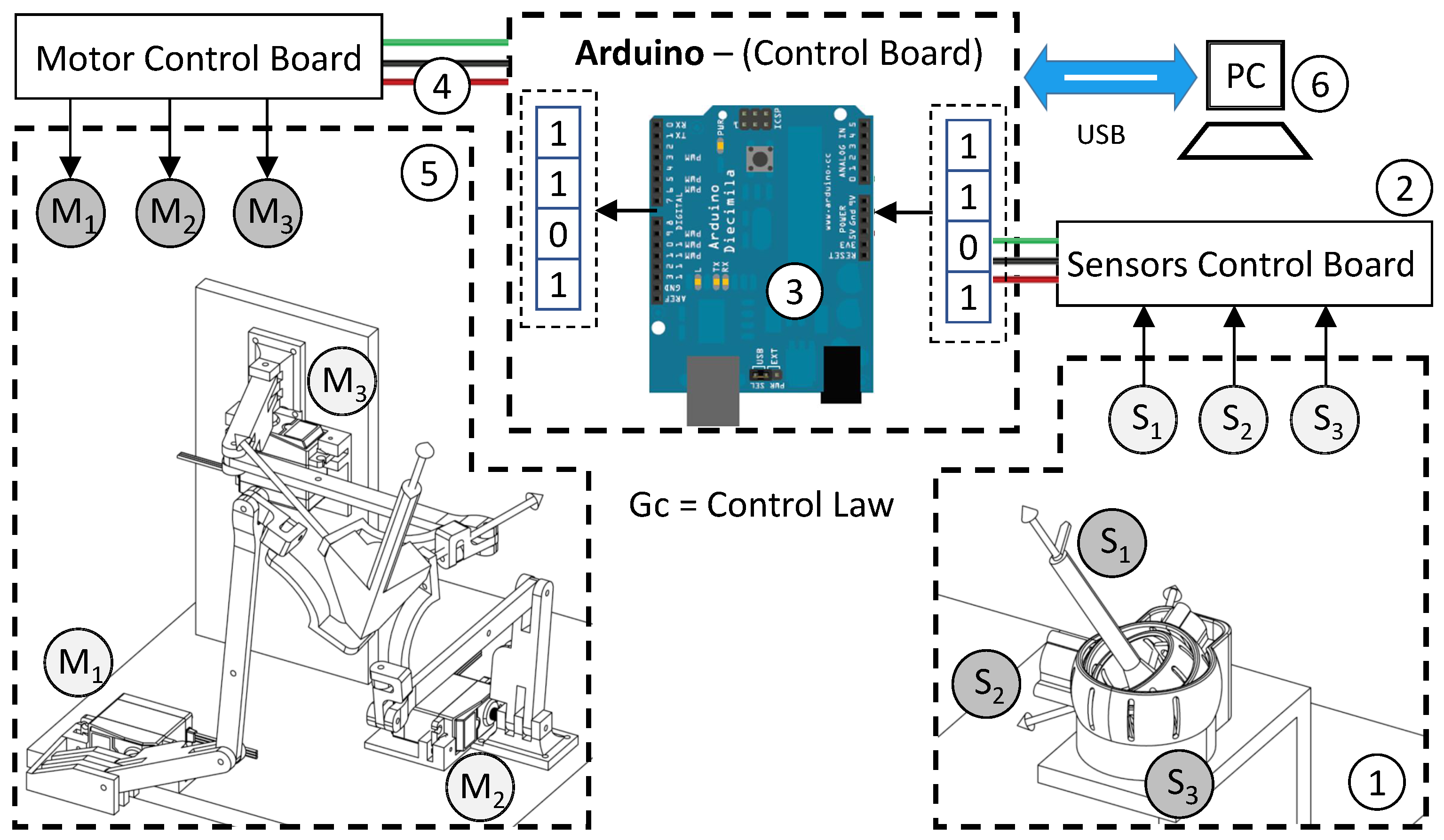
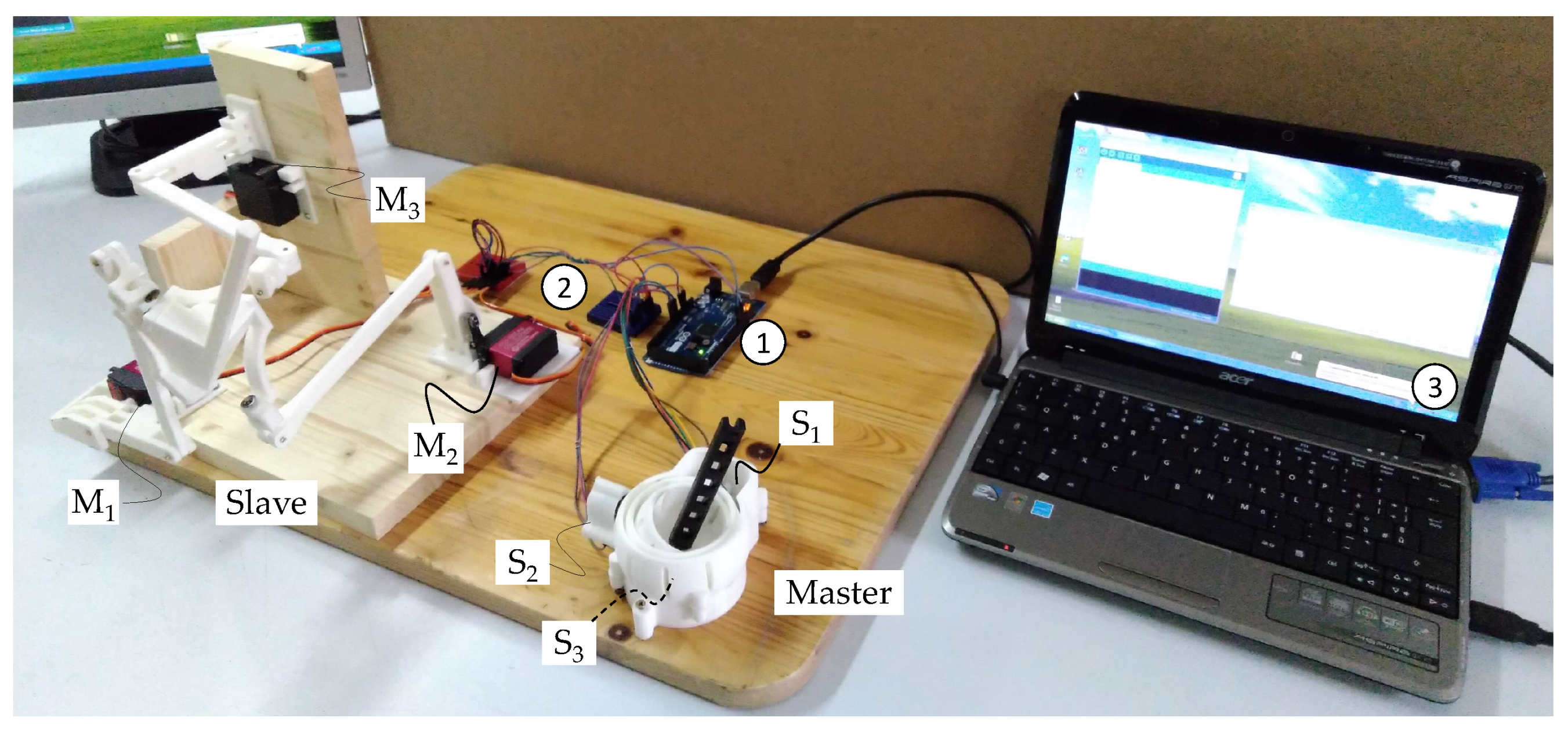
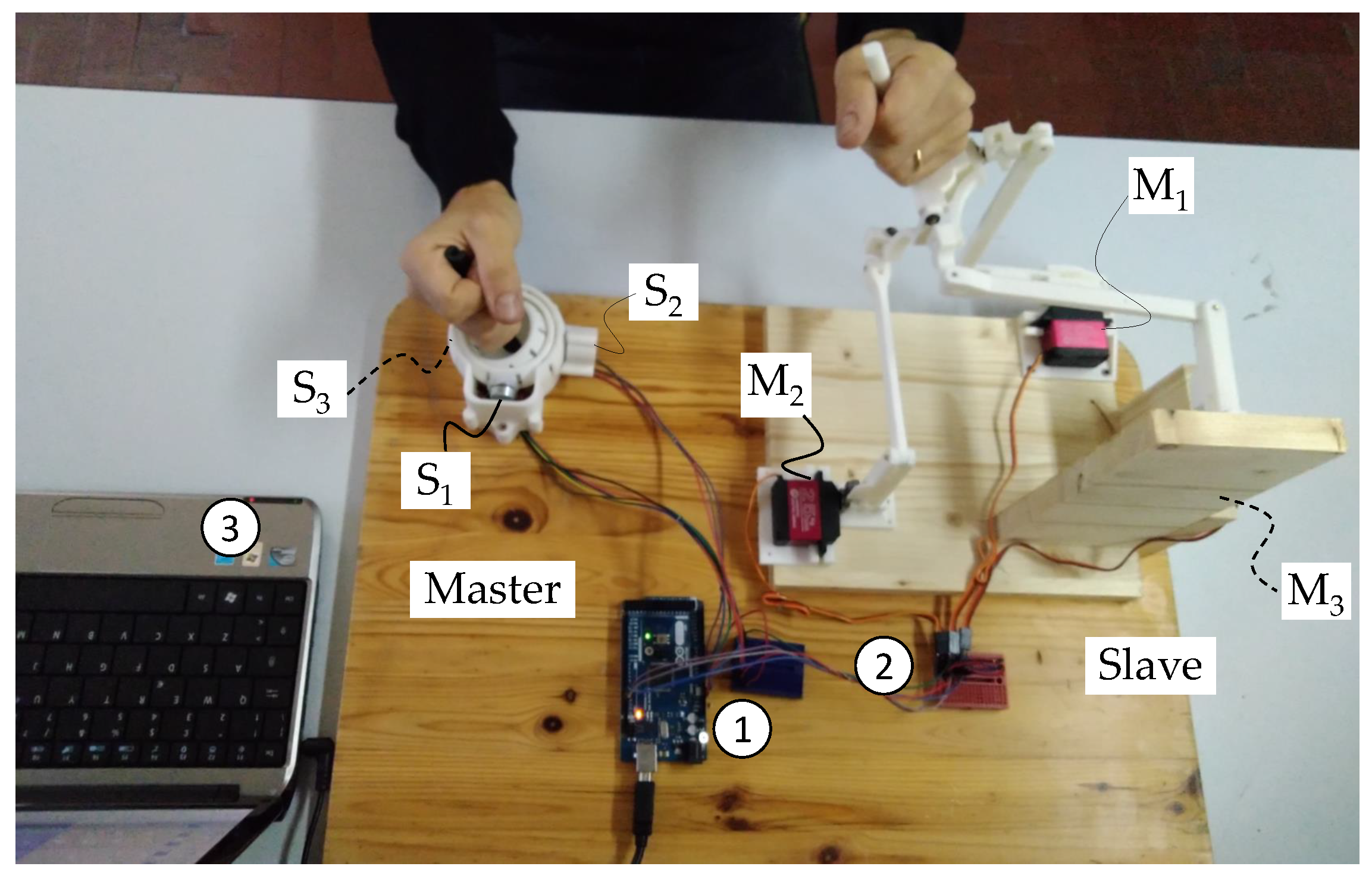
5. Experimental Set-Up of the System

The layout of the proposed system is shown in Figure 15 following a mechatronic architecture shown in [42,43]. The input signals of the servo-system are the reference signals θ 1 , θ 2 , θ 3 -SET, which correspond to the time position laws of the gimbal. They are sent to control board, which uses a control law G c for generating the signals θ M 1 , θ M 2 , θ M 3 -SET for the motors. G c implements the inverse kinematics of the slave mechanism. In the closed-loop regulator, the θ M i -SET are compared with the feedback signals θ M i -F/B, which are compensated by the signal conditioning K θ of the angular transducers connected to the motors shafts. The error ϵ is compensated through the proportional controller P, such that the outputs θ M 1 , θ M 2 , θ M 3 -REF are the command signals of the three small servomotors of the slave system. The θ M i -OUT signals, which are related to the shaft angular position of the motors, change the configuration of the slave to follow the θ i -SET signals of the master minimizing the error.
Figure 16 shows the overall control scheme, in which a PC, labeled (6), is used for programming and monitoring the operation and finally recording the trial. It is worth noting that after initial programming and calibration, the system is able to work and to interact automatically with the end-user. The end-user grasps the joysticks of the master and slave systems at the same time. The healthy hand plays as the master; therefore, the gimbal (1) is completely passive and follows the movements. The encoders, named as S1, S2 and S3, measure the angular configuration (orientation) of the system and their values, θ i -SET are sent through a sensors control board (2) to the Arduino control board (3). The resulting signals θ M 1 , θ M 2 , θ M 3 -SET are generated by the G c control law and sent to the motor control board (4) to operate the motors of the slave system to move the affected hand. It is worth noting that either a mirror movement or the same of the slave can be generated, according to the programming of the system at the beginning of the trial.
The Arduino Electronic Board is used to control the small servomotors to actuate the slave, they have a power supply of 4.8 V, maximum torque 2.45 Nm and rotation speed of 2 π / s . Figure 16 shows a scheme with the basic components, they are used for the primary task of monitoring and eventually recording the orientation of the healthy and affected hands. Nevertheless, the use of force sensors on the joysticks may be considered in order to increase safety during the operation, i.e., the system stops if the grasping forces in one or both hands increase or decrease rapidly. This option will be further implemented.
The preliminary mechatronic prototype of the system is reported in Figure 17 and Figure 18. As mentioned previously, the system is basically composed by two units, the master is interacting with the full functional upper wrist, while the slave is devoted to the affected upper wrist.
Another important outcome of the proposed system is moving towards the e-healthcare, providing a portable system, relatively at low cost, with mechatronic solutions that allow the remote monitoring and recording of the trials to be supervised even at a distance.

6. Conclusions

We presented the design, analysis and experimental set-up of a master/slave system dedicated to wrist rehabilitation. The basic idea was to convey the motion of the healthy wrist imposed to a gimbal-like mechanism to the affected wrist moved by a mechanism with a parallel geometry. This solution combines the simplicity of the master design with the accuracy of the slave geometry. According to the analysis and simulation outcomes, the master/slave map is an identity except when the motor links rotations of the parallel mechanism approach the upper limits. The ranges of rotation either of the joystick or of the driving motors can be considered acceptable for the application proposed. The simulations allow the authors to select the driving motors and to arrange a mechatronic set-up of the entire system. Experimental tests will be the main subject of the future work.

Author Contributions

Conceptualization, M.R. and P.R.; software, M.R. and P.R.; formal analysis, M.R. and P.R.; investigation, M.R. and P.R.; writing—original draft preparation, M.R. and P.R.; writing—review and editing, M.R. and P.R. All authors have read and agreed to the published version of the manuscript.

Funding

This research received no external funding.

Institutional Review Board Statement

Not applicable.

Informed Consent Statement

Not applicable.

Data Availability Statement

The data presented in this study are available on request from the corresponding author.

Conflicts of Interest

The authors declare no conflict of interest.

References

  1. Kahn, L.E.; Zygman, M.L.; Rymer, W.Z.; Reinkensmeyer, D.J. Robot-assisted reaching exercise promotes arm movement recovery in chronic hemiparetic stroke: A randomized controlled pilot study. J. Neuroeng. Rehabil. 2006, 3, 12. [Google Scholar] [CrossRef] [Green Version]
  2. Colombo, R.; Pisano, F.; Micera, S.; Mazzone, A.; Delconte, C.; Carrozza, M.C.; Dario, P.; Minuco, G. Robotic techniques for upper limb evaluation and rehabilitation of stroke patients. IEEE Trans. Neural Syst. Rehabil. Eng. 2005, 13, 311–324. [Google Scholar] [CrossRef] [PubMed]
  3. Rea, P.; Ottaviano, E.; Conte, M.; D’Aguanno, A.; De Carolis, D. The design of a novel tilt seat for inversion therapy. Int. J. Imaging Robot. 2013, 11, 1–10. [Google Scholar]
  4. Lum, P.S.; Burgar, C.G.; Shor, P.C.; Majmundar, M.; Van der Loos, M. Robot-assisted movement training compared with conventional therapy techniques for the rehabilitation of upper-limb motor function after stroke resonance imaging in healthy subjects. Arch. Phys. Med. Rehabil. 2002, 83, 952–959. [Google Scholar] [CrossRef] [PubMed] [Green Version]
  5. Lo, A.; Guarion, P.; Richards, L.; Haselkorn, J.; Wittenberg, G.; Federman, D.; Ringer, R.; Wagener, T.; Krebs, H.; Volpe, B.; et al. Robot assisted therapy for long-term upper-limb impairment after stroke. N. Engl. J. Med. 2010, 362, 1772–1783. [Google Scholar] [CrossRef] [PubMed] [Green Version]
  6. Masiero, S.; Celia, A.; Rosati, G.; Armani, M. Robotic-assisted rehabilitation of the upper limb after acute stroke. Arch. Phys. Med. Rehabil. 2007, 88, 142–149. [Google Scholar] [CrossRef] [PubMed]
  7. Lewis, G.; Perreault, E. An Assessment of Robot-Assisted Bimanual Movements on Upper Limb Motor Coordination Following Stroke. IEEE Trans. Neural Syst. Rehabil. Eng. 2010, 17, 595–604. [Google Scholar] [CrossRef]
  8. Krebs, H.I.; Hogan, N.; Aisen, M.; Volpe, B.T. Robot-aided neurorehabilitation. IEEE Trans. Rehabil. Eng. 1998, 6, 75–87. [Google Scholar] [CrossRef] [PubMed] [Green Version]
  9. Harwin, W.S.; Patton, J.L.; Edgerton, V.R. Challenges and opportunities for robot-mediated neurorehabilitation. Proc. IEEE 2006, 94, 1717–1726. [Google Scholar] [CrossRef]
  10. Lum, P.S.; Burgar, C.G.; Van der Loos, M.; Shor, P.C.; Majmundar, M.; Yap, R. The mime robotic system for upper-limb neuro-rehabilitation: Results from a clinical trial in subacute stroke. In Proceedings of the IEEE 9th International Conference on Rehabilitation Robotics, Chicago, IL, USA, 28 June–1 July 2005. [Google Scholar]
  11. He, J.; Koeneman, E.J.; Schultz, R.; Herring, D.; Wanberg, J.; Huang, H.; Sugar, T.; Herman, R.; Koeneman, J.B. Design of a robotic upper extremity repetitive therapy device. In Proceedings of the IEEE 9th International Conference on Rehabilitation Robotics, Chicago, IL, USA, 28 June–1 July 2005. [Google Scholar]
  12. Mayhew, D.; Bachrach, B.; Rymer, W.Z.; Beer, R.F. Development of the macarm—A novel cable robot for upper limb neurorehabilitation. In Proceedings of the IEEE 9th International Conference on Rehabilitation Robotics, Chicago, IL, USA, 28 June–1 July 2005. [Google Scholar]
  13. Homma, K.; Fukuda, O.; Sugawara, J.; Nagata, Y.; Usuba, M. A wire-driven leg rehabilitation system: Development of a 4-dof experimental system. In Proceedings of the 2003 IEEE/ASME International Conference on Advanced Intelligent Mechatronics, Kobe, Japan, 20–24 July 2003; pp. 908–913. [Google Scholar]
  14. Zhang, L.; Zou, Y.; Wang, L.; Pei, X. Hybrid force control based on icmac for an astronaut rehabilitative training robot. Int. J. Adv. Robot. Syst. 2012, 9, 55. [Google Scholar] [CrossRef] [Green Version]
  15. Rea, P.; Ottaviano, E. Functional Design for Customizing Sit-To-Stand Assisting Devices. J. Bionic Eng. 2018, 15, 83–93. [Google Scholar] [CrossRef]
  16. Gonzalez-Rodriguez, A.; Castillo-Garcia, F.J.; Ottaviano, E.; Rea, P.; Gonzalez-Rodriguez, A.G. On the effects of the design of cable-Driven robots on kinematics and dynamics models accuracy. Mechatronics 2017, 43, 18–27. [Google Scholar] [CrossRef]
  17. Ottaviano, E.; Castelli, G. A Study on the Effects of Cable Mass and Elasticity in Cable-Based Parallel Manipulators. In ROMANSY 18 Robot Design, Dynamics and Control; CISM International Centre for Mechanical Sciences, Courses and Lectures; Springer: Vienna, Austria, 2010; Volume 524, pp. 149–156. [Google Scholar]
  18. Masiero, S.; Armani, M.; Rosati, G. Upper-limb robot-assisted therapy in rehabilitation of acute stroke patients: Focused review and results of new randomized controlled trial. J. Rehabil. Res. Dev. 2011, 48, 355–366. [Google Scholar] [CrossRef]
  19. Rosati, G.; Gallina, P.; Masiero, S.; Rossi, A. Design of a new 5 d.o.f. wire based robot for rehabilitation. In Proceedings of the IEEE 9th International Conference on Rehabilitation Robotics, Chicago, IL, USA, 28 June–1 July 2005. [Google Scholar]
  20. Tappeiner, L.; Ottaviano, E.; Husty, M.L. Cable-Driven Robot for Upper Limb Rehabilitation Inspired by the Mirror Therapy. Mech. Mach. Sci. 2018, 50, 174–181. [Google Scholar]
  21. Beom, J.; Koh, S.; Nam, H.S.; Kim, W.; Kim, Y.; Seo, H.G.; Oh, B.-M.; Chung, S.-G.; Kim, S. Robotic Mirror Therapy System for Functional Recovery of Hemiplegic Arms. J. Vis. Exp. 2016, 114, 54521. [Google Scholar] [CrossRef]
  22. Hamzei, F.; Läppchen, C.H.; Glauche, V.; Mader, I.; Rijntjes, M.; Weiller, C. Functional plasticity induced by mirror training: The mirror as the element connecting both hands to one hemisphere. Neurorehabilit. Neural Repair 2012, 26, 484–496. [Google Scholar] [CrossRef] [PubMed]
  23. Dohle, C.; Püllen, J.; Nakaten, A.; Küst, J.; Rietz, C.; Karbe, H. Mirror therapy promotes recovery from severe hemiparesis: A randomized controlled trial. Neurorehabilit. Neural Repair 2009, 23, 209–217. [Google Scholar] [CrossRef] [PubMed]
  24. Pervane Vural, S.; Nakipoglu Yuzer, G.F.; Sezgin Ozcan, D.; Demir Ozbudak, S.; Ozgirgin, N. Effects of Mirror Therapy in Stroke Patients with Complex Regional Pain Syndrome Type 1: A Randomized Controlled Study. Arch. Phys. Med. Rehabil. 2016, 97, 575–581. [Google Scholar] [CrossRef]
  25. Grünert-Plüss, N.; Hufschmid, U.; Santschi, L.; Grünert, J. Mirror therapy in hand rehabilitation: A review of the literature, the st gallen protocol for mirror therapy and evaluation of a case. Br. J. Hand Ther. 2008, 13, 4–11. [Google Scholar] [CrossRef]
  26. Rothgangel, A.; Braun, S. Mirror Therapy: Practical Protocol for Stroke Rehabilitation; Pflaum Verlag: Munich, Germany, 2013. [Google Scholar] [CrossRef]
  27. Rothgangel, A.S.; Braun, S.M.; Beurskens, A.J.; Seitz, R.J.; Wade, D.T. The clinical aspects of mirror therapy in rehabilitation: A systematic review of the literature. Int. J. Rehabil. Res. 2011, 34, 1–13. [Google Scholar] [CrossRef] [Green Version]
  28. Ramachandran, V.S.; Rogers-Ramachandran, D. Synaesthesia in phantom limbs induced with mirrors. Proc. R. Soc. Lond. 1996, 263, 377–386. [Google Scholar]
  29. Dere, E.; Ozcan, M.; Canan, S. Three Axis Gimbal Design and Its Application. In Proceedings of the International Conference on Advanced Technologies, Computer Engineering and Science (ICATCES’18), Safranbolu, Turkey, 11–13 May 2018. [Google Scholar]
  30. Shah, D.; Wu, Y.; Scalzo, A.; Metta, G.; Parmiggiani, A. A Comparison of Robot Wrist Implementations for the iCub Humanoid. Robotics 2019, 8, 11. [Google Scholar] [CrossRef] [Green Version]
  31. Callegari, M.; Cammarata, A.; Gabrielli, A.; Ruggiu, M.; Sinatra, R. Analysis and design of a spherical micromechanism with flexure hinges. J. Mech. Des. 2009, 131, 051003. [Google Scholar] [CrossRef]
  32. Rodriguez, J.; Ruggiu, M. A novel method for the solution of the forward displacement problem of spherical parallel manipulators. ZAMM J. Appl. Math. Mech. 2013, 93, 73–82. [Google Scholar] [CrossRef]
  33. Deidda, R.; Mariani, A.; Ruggiu, M. On the kinematics of the 3-RRUR spherical parallel manipulator. Robotica 2010, 28, 821–832. [Google Scholar] [CrossRef]
  34. Malosio, M.; Negri, S.P.; Pedrocchi, N.; Vicentini, F.; Caimmi, M.; Tosatti, L.M. A spherical parallel three degrees-of-freedom robot for ankle-foot neuro-rehabilitation. In Proceedings of the 2012 Annual International Conference of the IEEE Engineering in Medicine and Biology Society, San Diego, CA, USA, 28 August–1 September 2012; pp. 3356–3359. [Google Scholar]
  35. Bian, H.; Liu, Y.H.; Liang, Z.C.; Zhao, T. A Novel 2-RRR/UPRR robot mechanism for ankle rehabilitation and its kinematics. Robot 2010, 32, 6–12. [Google Scholar] [CrossRef]
  36. Zhang, L.Y.; Li, J.F.; Dong, M.J. Design and workspace analysis of a parallel ankle rehabilitation robot (PARR). J. Healthc. Eng. 2019, 2019, 4164790. [Google Scholar] [CrossRef] [PubMed]
  37. Du, Y.; Li, R.; Li, D.; Bai, S. An ankle rehabilitation robot based on 3-RRS spherical parallel mechanism. Adv. Mech. Eng. 2017, 9, 1–8. [Google Scholar] [CrossRef] [Green Version]
  38. Zhang, J.; Liu, C.; Liu, T.; Qi, K.; Niu, J.; Guo, S. Module combination based configuration synthesis and kinematic analysis of generalized spherical parallel mechanism for ankle rehabilitation. Mech. Mach. Theory 2021, 166, 104436. [Google Scholar] [CrossRef]
  39. He, P.; Kantu, N.T.; Xu, B.; Swami, C.P.; Saleem, G.T.; Kang, J. A Novel 3-RRR Spherical Parallel Instrument for Daily Living Emulation (SPINDLE) for Functional Rehabilitation of Patients with Stroke. Int. J. Adv. Robot. Syst. 2021, 18, 1–13. [Google Scholar] [CrossRef]
  40. Saadatzi, M.; David, C.; Long, D.C.; Celik, O. Comparison of Human-Robot Interaction Torque Estimation Methods in a Wrist Rehabilitation Exoskeleton. J. Intell. Robot. Syst. 2019, 94, 565–581. [Google Scholar] [CrossRef]
  41. Craig, J. Introduction to Robotics: Mechanics and Control, 4th ed.; Pearson College Div: London, UK, 2004. [Google Scholar]
  42. Ottaviano, E.; Rea, P.; Castelli, G. THROO: A tracked hybrid rover to overpass obstacles. Adv. Robot. 2014, 28, 683–690. [Google Scholar] [CrossRef]
  43. Rea, P.; Ottaviano, E. Design and Development of an Inspection Robotic System for Indoor Applications. Robot. Comput. Integr. Manuf. 2018, 49, 143–151. [Google Scholar] [CrossRef]
Figure 1. The master mechanism.
Actuators 11 00014 g001
Figure 2. The slave mechanism.
Actuators 11 00014 g002
Figure 3. Tait–Bryan angles in the master mechanism.
Actuators 11 00014 g003
Figure 4. Slave mechanism at home pose.
Actuators 11 00014 g004
Figure 5. Slave mechanism in an arbitrary pose.
Actuators 11 00014 g005
Figure 6. The conics and the circumference in the Euler parameters plane { e 01 , e 11 } .
Actuators 11 00014 g006
Figure 7. Geometric model for θ 1 i u , θ 1 i d calculation.
Actuators 11 00014 g007
Figure 8. Master to slave R z mapping.
Actuators 11 00014 g008
Figure 9. Mechanism configuration at t = 7.5 s.
Actuators 11 00014 g009
Figure 10. Master to slave R x mapping.
Actuators 11 00014 g010
Figure 11. Master to slave R y mapping.
Actuators 11 00014 g011
Figure 12. Mechanism configuration at t = 17.5 s.
Actuators 11 00014 g012
Figure 13. Mechanism configuration at t = 27.5 s.
Actuators 11 00014 g013
Figure 14. Mechanism configuration at t = 38.5 s.
Actuators 11 00014 g014
Figure 15. Block scheme of the control.
Actuators 11 00014 g015
Figure 16. System control scheme.
Actuators 11 00014 g016
Figure 17. An overview of the proposed test bed of the mechatronic system.
Actuators 11 00014 g017
Figure 18. Top view of the proposed test bed of the mechatronic system.
Actuators 11 00014 g018
Publisher’s Note: MDPI stays neutral with regard to jurisdictional claims in published maps and institutional affiliations.

