1. Introduction
The development of new actuators able to provide a continuous control of the fuel injection rate aimed to the NO-soot trade-off during the fuel combustion is a research topic of great interest, since the first decade of the 2000s. Such a task requires a suitable shaping of the injection-rate profile during the engine operation through a continuous and controlled needle lift which modulates the fuel flow through the injector nozzle. This paradigm could be implemented by the aid of multi-functional materials, such as piezo-ceramics, magnetostrictives, or other alloys, able, in principle, to directly transduce an electric signal into a displacement. The aim can be accomplished by employing a suitable actuation device able to provide a full controlled continuous motion of the needle, withstanding the fuel high pressures.
Fuel injectors has experienced quite an evolution in the control of the injection rate. First diesel injectors were fully passive [
1,
2]. Indeed, in this type, a needle is pushed upward by the increase of the fuel pressure inside the atomizer, during the delivery phase, and then it is held in rest position by the reaction force of a calibrated spring: the operation, therefore, is just mechanical-hydraulic, determined by the calibration of the spring, the masses of the moving parts, and the internal fuel pressures. Then, it is clear that there is no true control in the opening and closure, nor in the injection time, that is fixed by the previous parameters that, obviously, cannot be controlled once the injector is assembled. The basic working principle of the more recent electromagnetic fuel injectors in diesel engines is the following [
3,
4]: the electromagnetic injector (for common rail systems) experiences the high pressure of the fuel, generated and controlled by the pump. Inside the injector, the fuel flux is divided into two branches: the main, feeding the injector itself, and a secondary one for the management of a rod controlling the needle aperture/closure. The last branch acts directly onto a “control volume” that, by means of a balance of pressures, at a disabled electromagnetic actuator, keeps the rod and the needle at rest position. Once the actuator coil has been energized, the control volume is unbalanced, and the spring acting on the rod opens the needle in the nozzle, thus allowing the fuel to flow. The injection process stops once the electromagnetic actuator is switched off. This is a rather complex system that allows to control the fuel injection timing, while the opening and closure profiles are somewhat fixed.
In recent years, actuators based on piezoelectric stacks have been proposed. The idea is based on the piezoelectric effect taking place in natural or artificial materials and alloys, such as PZT (lead zirconate titanate, Pb(Zr
Ti
)O
), that are supposed to be used for hydrogen-fueled, diesel, or gasoline combustion engines, in automotive applications [
5,
6,
7,
8]. The piezo-driven injection system has a short injection delay and quickly reaches the maximum injection rate compared to the solenoid-driven injection system. The atomization performance of the piezo-driven injection system is superior to that of the electromagnetic-driven one due to a faster response time and higher injection rate [
9,
10,
11]. However, piezo-stack injectors may need high driving voltages and suffer from delamination phenomena, which implies low lifespan. Moreover, they require a quite complex mechanical design [
12].
Besides the actual development of those kind of piezo-actuated injectors, a complementary solution is represented by a magnetostrictive-actuated injector [
13], in which the active material responds elastically to the magnetic field induced by a solenoid coil and elongates. Then, the needle and the aperture/closure phases can be directly controlled by the magnetostrictive rod. The pilot-valve response is significantly sped up with this technology [
14], and the injector can exploit the fast injection-rate, even at very high pressure levels, since a magnetostrictive material can withstand relatively high pressures/forces [
15]. Then, magnetostrictive (MS) based injectors could both have a simpler design and allow the full control of the fuel injection rate profile by following a certain reference signal, as shown in the following.
The most known material for the purpose is Terfenol-D, a Terbium-Iron-Dysprosium alloy showing
giant magnetostriction up to 1500 ppm, i.e., about 150
m with a 100 mm rod length. In perspective, this allows a quite compact MS-based injector system. The deformation of giant magnetostrictive materials is a function of the applied magnetic field and of the mechanical stress experienced by the sample. Typically, the maximum stroke behavior with respect to the stress has a maximum achieved at a compressive stress in the 5–20 MPa range, and, after, it decreases [
15,
16]. Then, in order to fully exploit the magnetostriction for linear actuation, a pre-stress mechanical system is needed, as it is presented in the following.
Magnetostrictive actuators have been proposed for different aims spanning, for example, from complex actuation functions [
17] to active noise cancellation [
18]. The development of magnetostrictive actuators for fuel injection has been tackled since the beginning of the 2000s, as witnessed by the contributions available in the literature. For the sake of example, in Reference [
19], the employment of a magnetostrictive actuator for the design of a hybrid MS/Hydraulic pump was presented, and the high energy densities shown by magnetostrictive materials were exploited. Later, in Reference [
20], a first attempt to design a fuel injector based on a MS actuator was proposed. In that case, a set of MS rods was employed in a Z-shaped tandem case, a set with a capability to inject fuel up to 160 MPa. Further studies [
21,
22] proposed the design of a new MS actuator for fuel injection by a direct drive of the needle through the magnetostrictive rod. The latter developed a system able to perform
m stroke within 30 ms and about
MPa pressure, performing the analysis and design of a fuel injection system for Gasoline Direct Injection (GDI) engines, taking into account the influence of several parameters, such as nozzle length, input fuel pressure, etc. In addition, tests were performed at a relatively low pressure. Other contributions proposed the application of MS actuators for Compressed Natural Gas (CNG) fuel injection, with about
MPa inlet pressure [
23]. A recent review about MS fuel injection is available in Reference [
24].
This work describes the activity related to the feasibility study for this technology by discussing a brief electromagnetic analysis, the design, and realization of a Terfenol-D actuator coupled to a standard passive diesel injector, modified for the purpose. The Terfenol rod provides the needle actuation and, through its precise micro-metric stroke, leads to a continuous modulation of the fuel mass flow rate. In perspective, a proof of principle of such a task would open also to the employment of cheaper magnetostrictive materials (Galfenol, Fe-Co, and Fe-Al alloys) with no content of Rare-earth elements, but this would require a more stringent analysis, design, and optimization of the device. Indeed, those other materials have a much lower magnetostriction effect [
16,
25] with respect to Terfenol-D, so we focused on the latter material.
The aim is to show the ability of the device to achieve fast injection, mass flow rate shaping, at higher working pressures with respect to the available literature and with direct simple geometry. Results have shown a good capability of the custom system to control, in open loop conditions, the fuel injection rate shape, as required for NO reduction, up to 50 MPa. This work could be further improved by refining and redesigning the hydraulic part of the system, which would be the aim of a future work.
3. The Custom MS Injector and Its Design
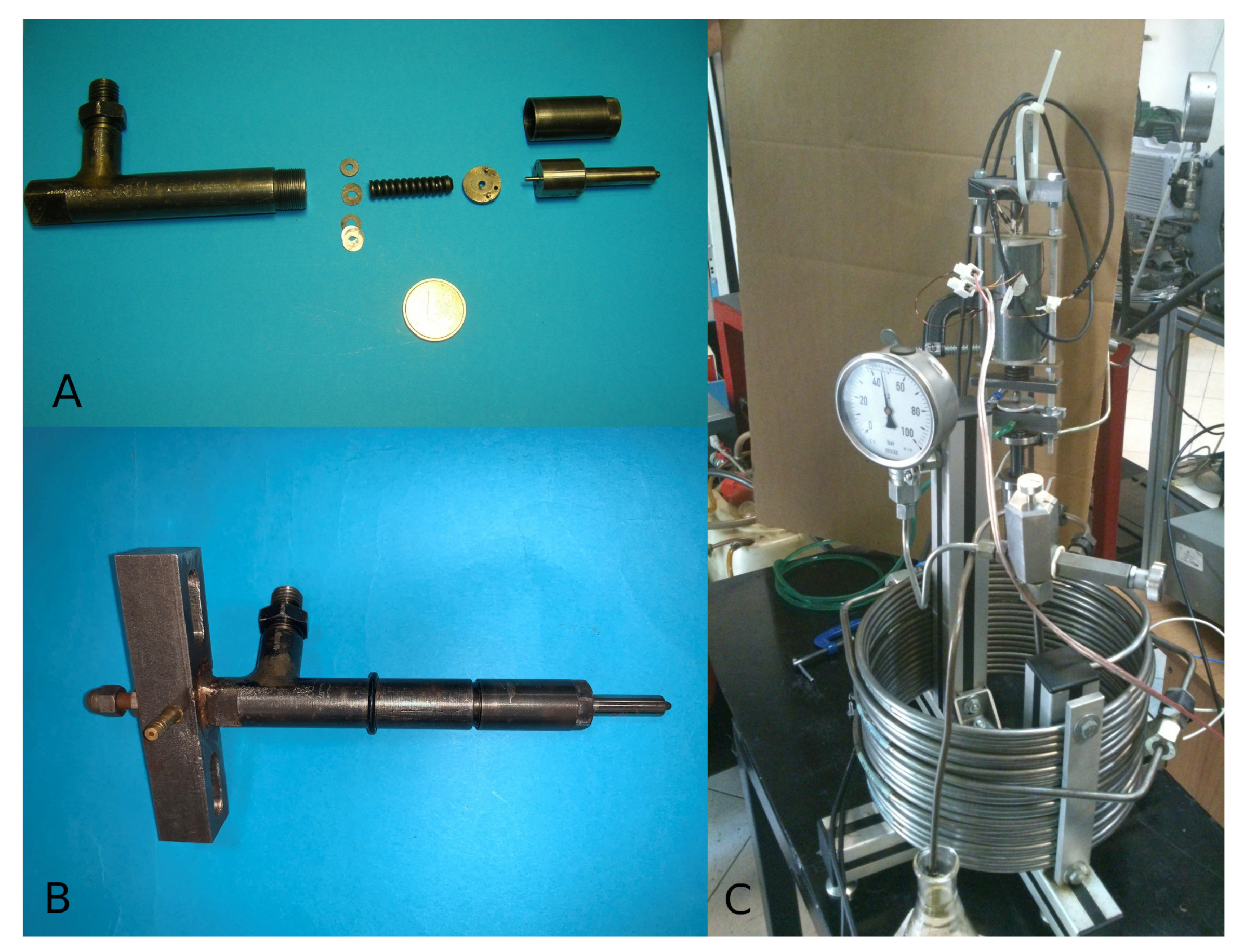
In order to implement the smart functionality, a commercial injector, shown in
Figure 2A, equipping diesel engines in the pre-common rail era, was modified to be driven by the MS actuator discussed so far. The starting apparatus is a full-mechanical actuated device, as described above, i.e., the retraction of the needle and the opening of the nozzle are driven by the raising fuel pressure (typically generated by the cam in the fuel pump) up to the counteraction of a calibrated spring (visible in
Figure 2A). Then, the nozzle closure is determined by the fuel pressure lowering at the end of the cycle. The injector was equipped with an axially-disposed single-hole nozzle
mm in diameter (nozzle length to diameter ratio equal l/D = 3) and operating at the maximum injection pressure of 100 MPa.
The main modification consisted of the removal of the spring mechanism and the extension of the needle elongation, by means of a steel rod, up to the back part of the injector body, to have a direct control of the nozzle opening/closure mechanism, while the original fuel adduction channel has been kept for the purpose. The modified injector is shown in
Figure 2B, where an iron bar, extended on both sides of the injector rear, is visible, connecting the MS actuator and closing the magnetic circuit.
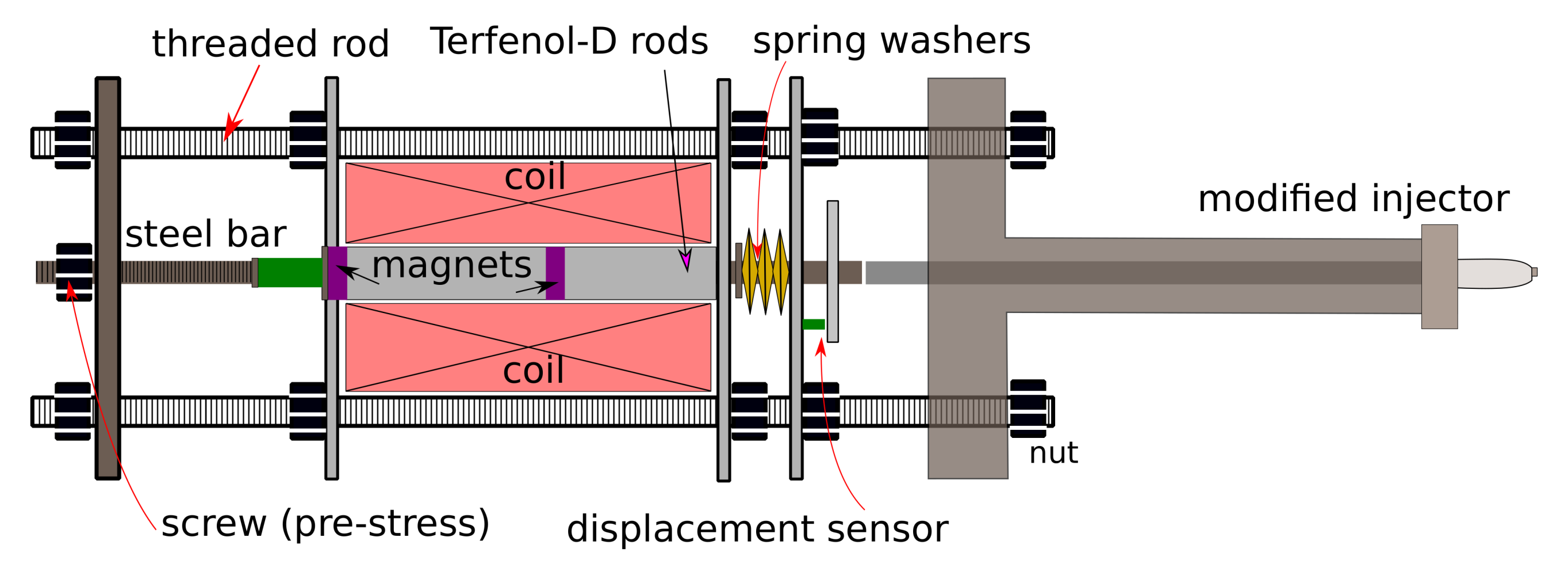
Figure 1 shows the sketch of the whole injection system and the integration of the magnetostrictive actuator with the commercial injector.
The magnetostrictive rod actuates the steel bar, which drives the commercial injector and its needle. The spring washers, driven by a screw at the actuator rear part, provide a tunable mechanical pre-stress able to guarantee the optimal stroke for the Terfenol rod. The threaded rods, the steel bar, the iron holder, and the steel structure of the injector allow the actuator to work approximately with a closed magnetic circuit, reducing air-gap effects and flux leakage.
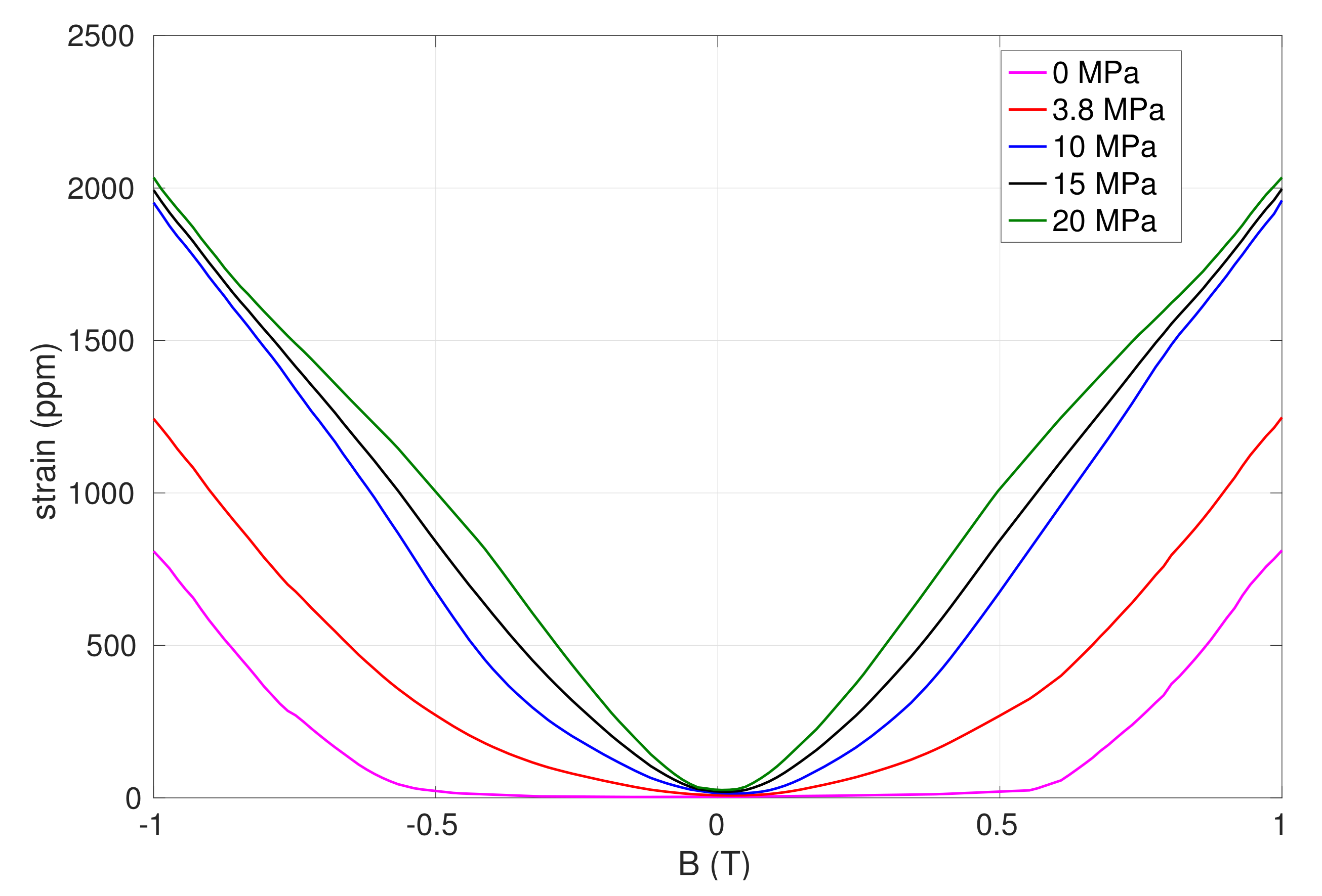
From the electromagnetic point of view, the first step in the design of the actuator is to consider the magnetostrictive curves of
Figure 3: since the adopted MS rods have a total length of
mm, then, a strain of 1000 ppm is necessary to have a maximum stroke of 100
m. This can be achieved at a magnetic induction of
T or of about
T for mechanical pre-stress of
MPa or 20 MPa, respectively. Then, in order to have more choices in this proof of principle, and by considering the non-ideal magnetic circuit, two permanent magnets (part S-10-10-N from supermagnete company) with a remanence of about
T are placed as shown in
Figure 1. The coil has
windings, and it can be estimated with the long solenoid approximation:
where
is the permeability of vacuum, and a maximum current of
A and a relative magnetic permeability
of the Terfenol-D rods [
16] are considered.
is larger than what is needed but has to be considered as an ideal unreachable value and leaves sufficient operability, taking into account the non-ideal behavior of the magnetic circuit, flux-leakages, etc., in this proof of principle.
4. Experimental Results and Discussion
The device was developed in the actual MS injector, as sketched in
Figure 1. The device was experimentally tested by measuring the repetitive fuel injection rate, according to the Bosch method [
26]; see
Figure 2C. The method is based on measuring the dynamic variations of pressure, induced by the injection event into a tube-like duct. The pressure sensor is a piezoquartz transducer, installed downstream of the injector nozzle. The pressure variations are proportional to the injection rate through geometrical parameters of the tube and chemical-physical properties of the fluid. It is worth noting that the Bosch method is characterized by
reflected waves of fluid pressure, related to the tube length and to the discontinuity at the end of the tube. Therefore, the repetition rate must be sufficiently slow to allow the reflected waves full attenuation [
26].
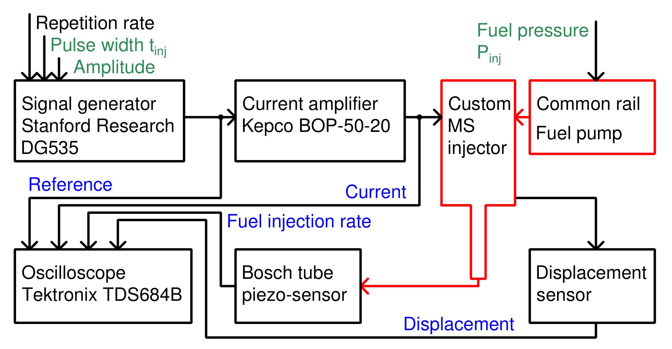
As schematized in
Figure 4, the experimental setup is composed by a pulse generator (Stanford Research Systems DG535), with repetition rate, pulse width (
), and amplitude as controllable parameters. The repetition rate has been set to 4 Hz for all the tests presented below, in order to have the reflected waves fully attenuated and a fuel injection rate starting at zero at each trigger pulse. The reference signal drives a current amplifier (Kepco BOP 50–20) feeding the MS actuator coil. A eddy-current sensor (Kaman SMU-9000), facing a disk coaxial to the actuator output, allows the measurement of the displacement, that is related to the needle lift. A common rail system and a fuel pump, controlled in pressure (P
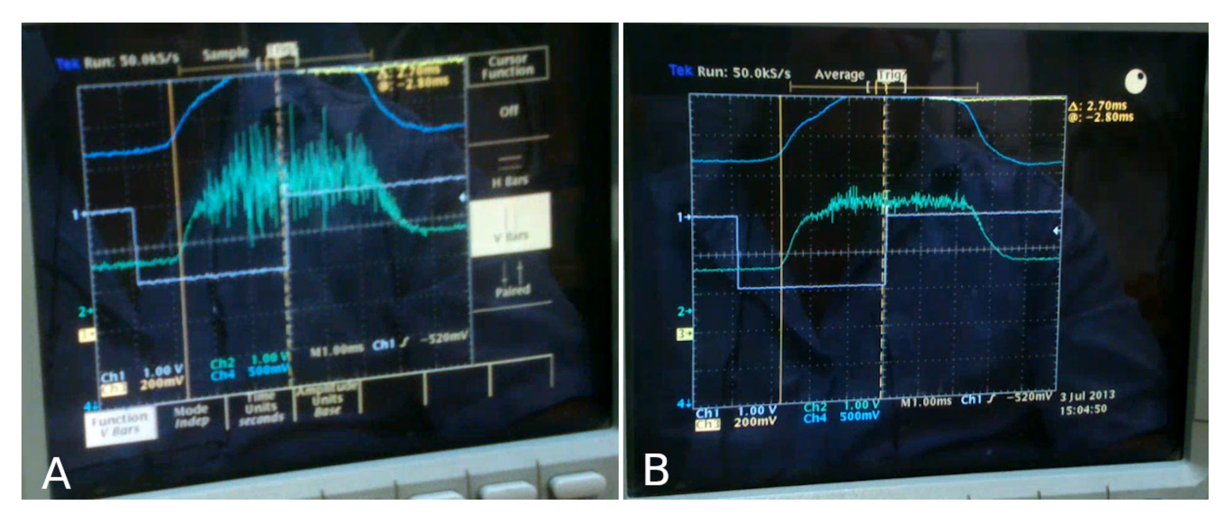
), provides the high-pressure fuel to the injector. The fuel injection rate signal, the coil current, the displacement, and the reference signal are triggered at the repetition rate, sampled, and stored in a digital oscilloscope set (Tektronix TDS684B). All the acquired signals have been averaged over tens of measurements by using an oscilloscope function, in order to cancel out the measurement noise, as shown in
Figure 5.
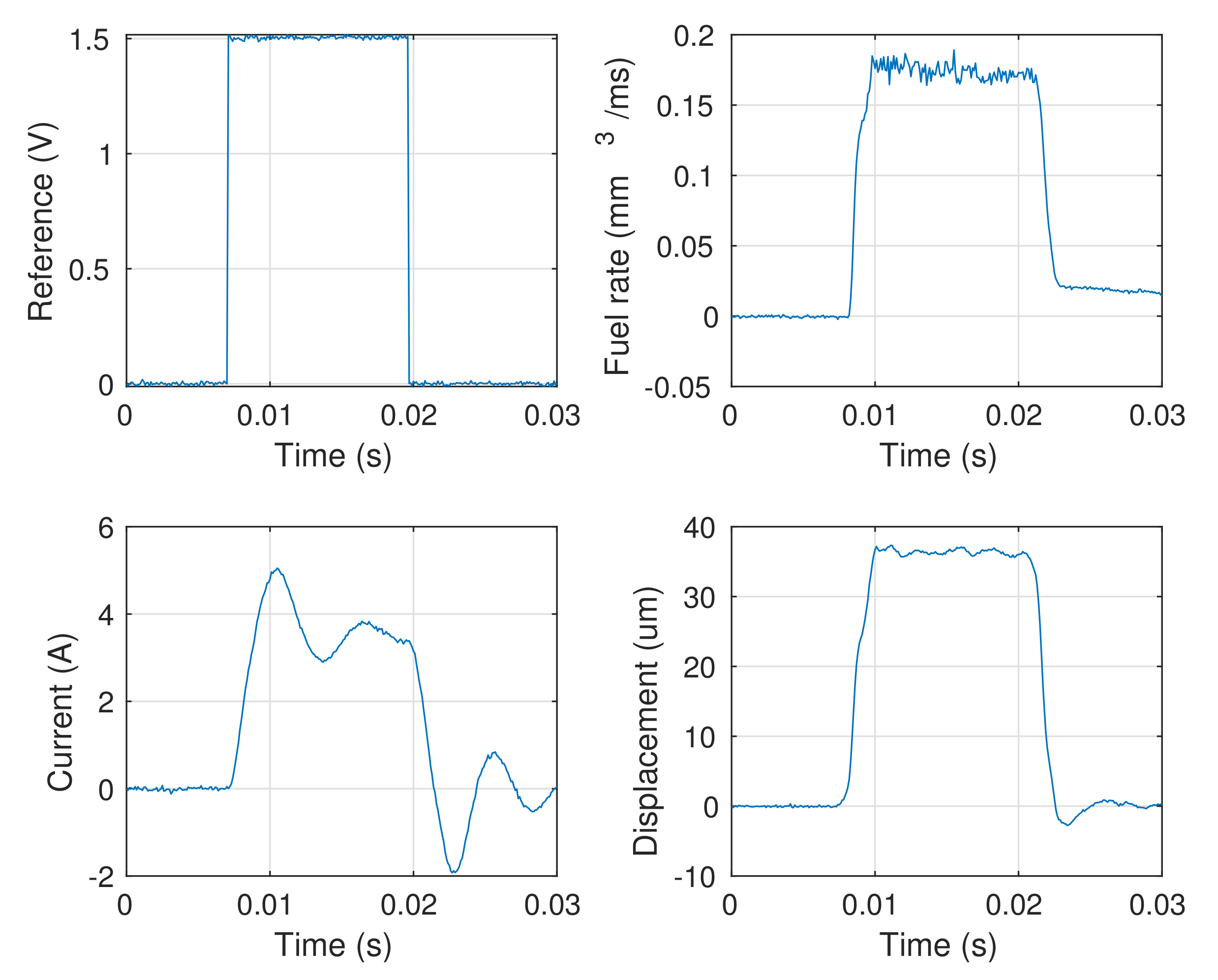
A standard fuel injector behaves with a constant fuel injection rate (on/off behavior), because the electromagnetic actuators cannot guarantee a continuous control of the nozzle aperture/closure. So, the test of
Figure 6, with P
MPa fuel pressure and
ms pulse width, was aimed to show that the custom actuator was able to reproduce such a behavior. The figure shows the square reference signal, the actuator current, the rod displacement, and the fuel injection rate. First of all, it is worth noting that the current amplitude is smaller than 10 A, and well within the range of currents of actual fuel injection systems, thus responding to the requirements of the commercial electronic control units (ECU) equipping current engines. The fuel injection rate has a constant and controllable delay, around 1 ms, with respect to the reference signal, and this is a very good result for being foreseen in the design phase and achieving fast pilot-valve responses. However, the fuel injection rate does not go to zero after the end of the reference signal. There are mainly two reasons for that: the first is related to the measurement technique, and the second may be related to the injector. Indeed, this is an intrinsic effect of the Bosch tube for the rate measurements. In fact, the injected fluid is delivered outside, through the long pipeline shown in
Figure 2C, accomplishing a constant inner pressure of about
MPa by a calibrated valve at the end. At the injection closure, a residual fuel remains in the injection chamber (where the nozzle is allocated in) that is low to flow and producing the described overpressure that goes to zero with an unrelated time. On the other hand, that behavior may be due to a non-full closure of the nozzle, once the magnetostrictive actuator is switched off. This would be still acceptable and could be easily solved in a more engineered prototype. However, more importantly, the fuel injection rate signal always starts from zero, as visible at the beginning of each pulse, and this is proves that the nozzle is fully closed at each new measurement.
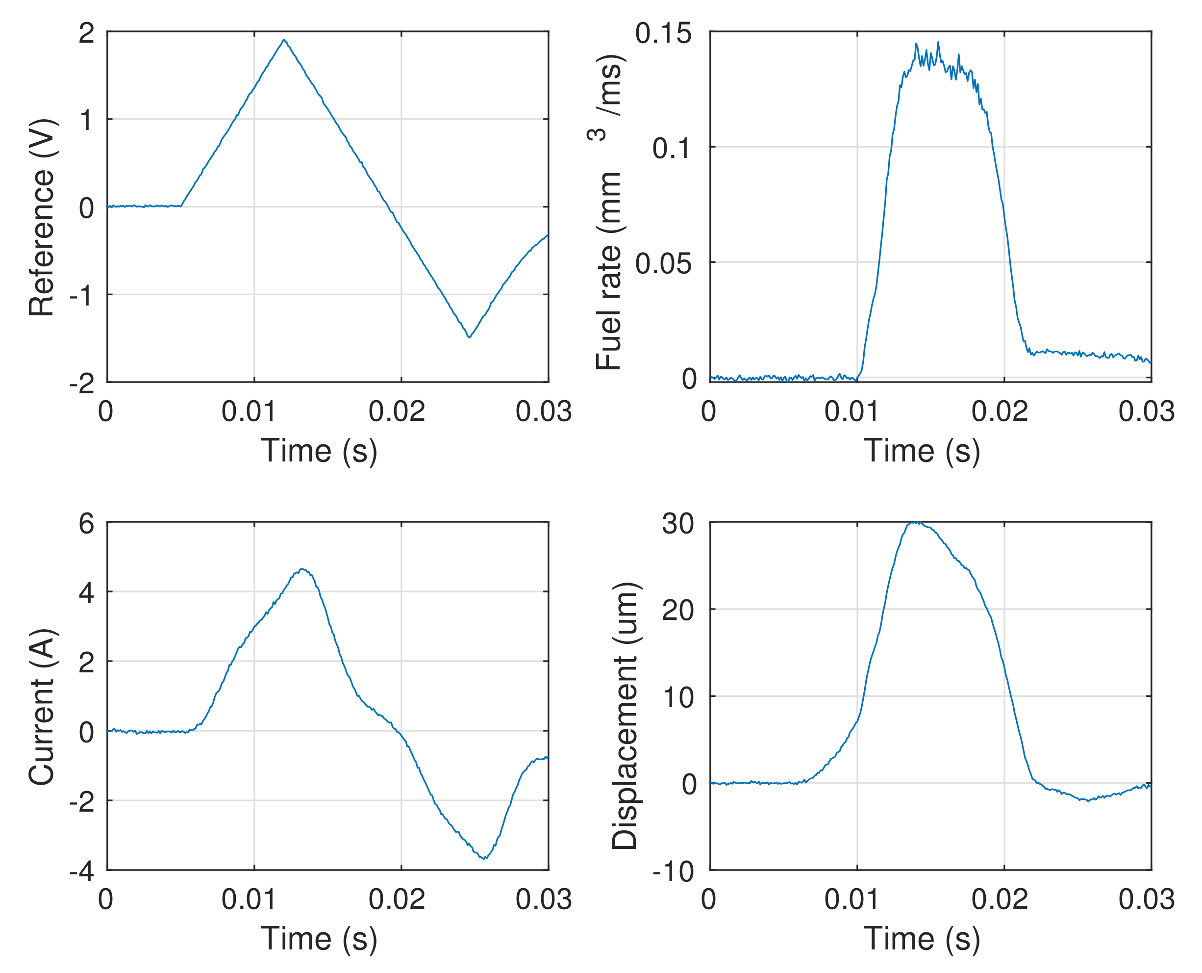
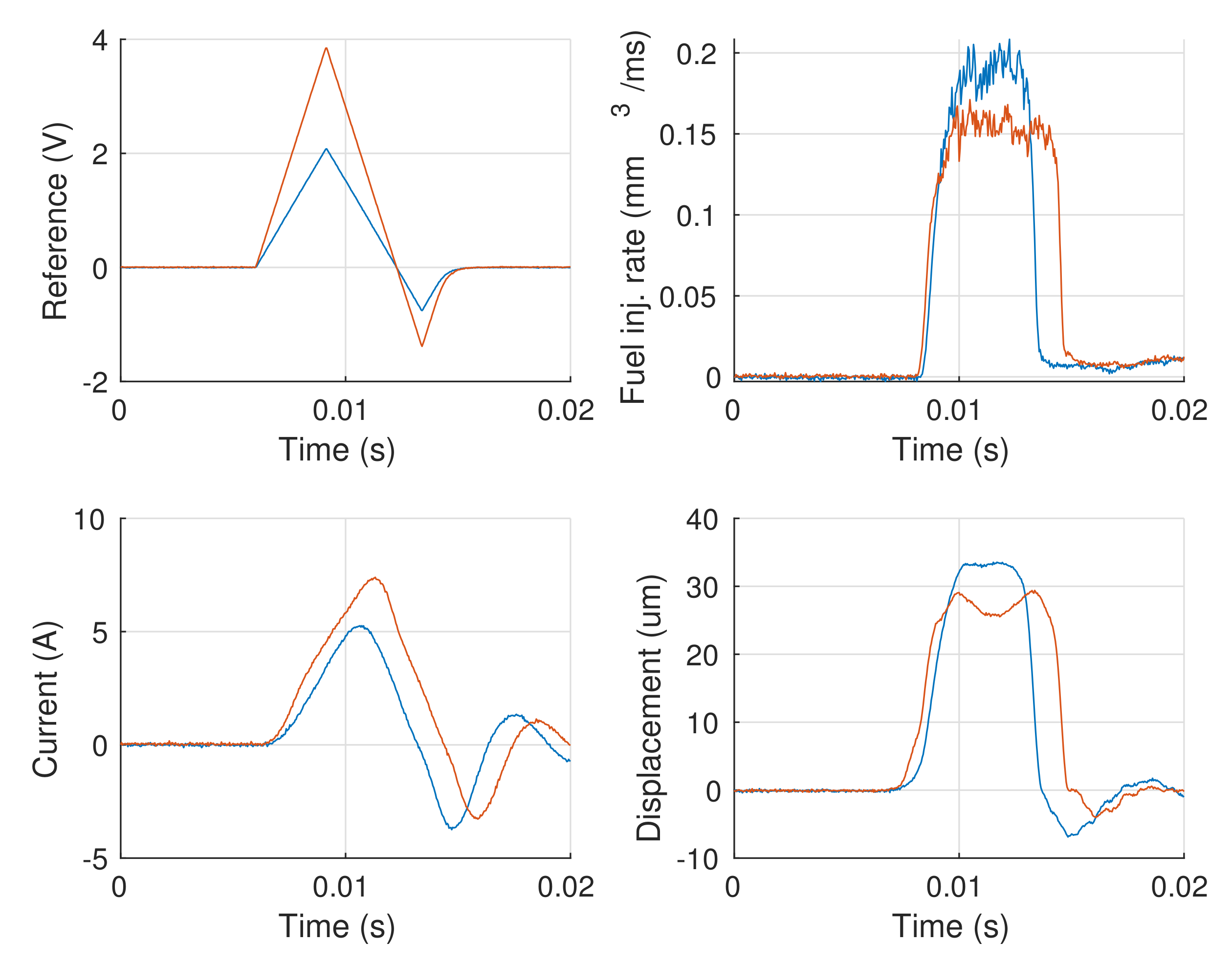
Figure 7 shows the measurement with a triangular-like reference, available in the adopted pulse generator, and the same parameters. It is quite evident that the injection rate is differently shaped with respect to the squared reference of
Figure 6. Then, this is proof that the fuel injection rate profile can be changed by exploiting different pulse shapes. Nevertheless, the shape is not exactly triangular, as the reference. The following considerations may apply: first, the injector and the actuator are connected through a steel rod about 150 mm long, and this may introduce delays and distortions in the movements because of the intrinsic rod dynamics at such high rates (for example, it is worth noting that the rise time of the signals is in the hundreds of microseconds range); second, the injector itself has a nozzle geometry aimed to a on/off behavior. Those issues could be solved with a properly designed geometry of the nozzle and a more compact injector, and this should give a far better controllability of the fuel injection rate.
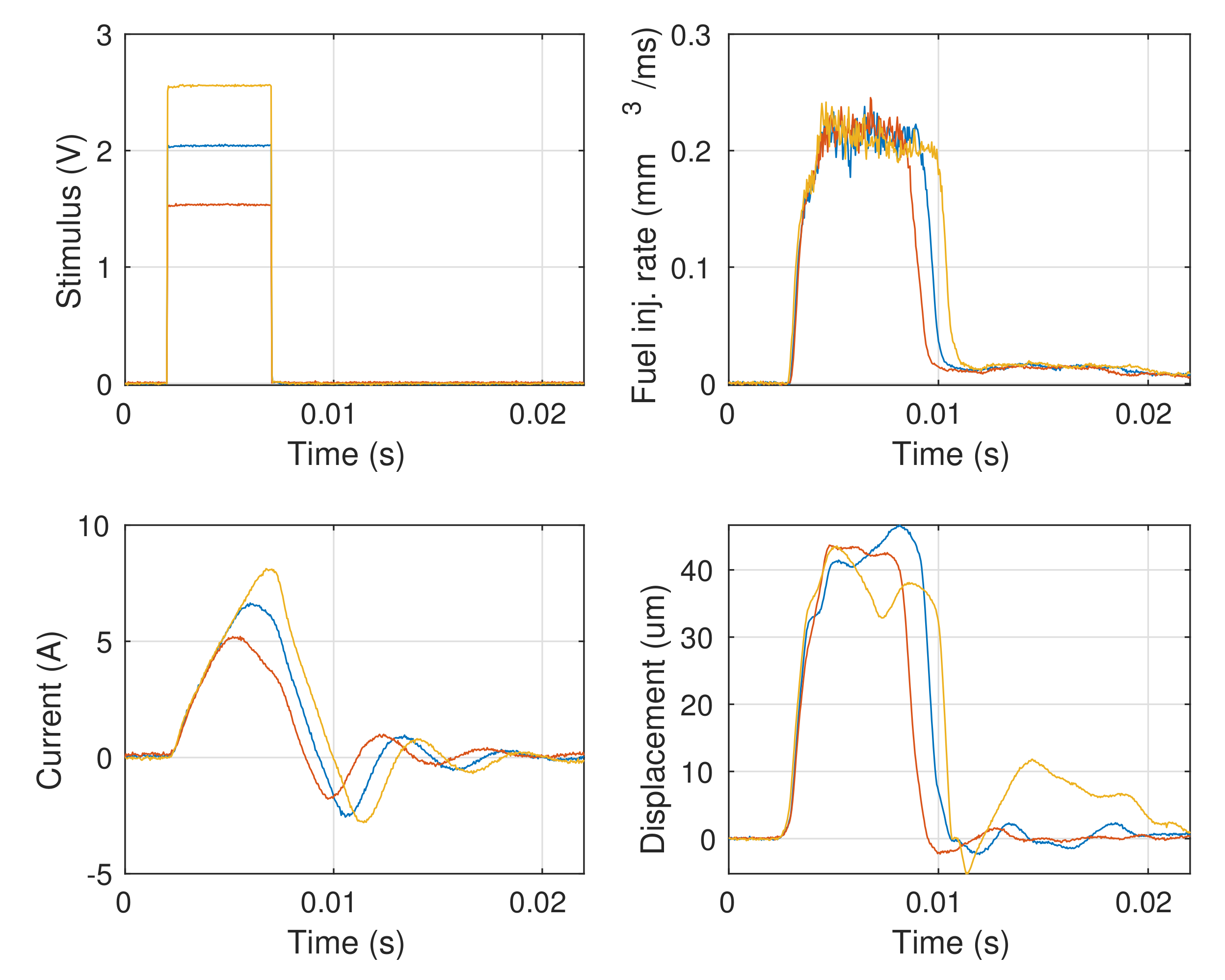
A second test is to verify the effect of the reference amplitude on the various signals.
Figure 8 shows the comparison among square-shaped signals at the injection pressure of P
MPa and shorter pulse width,
ms. The currents and the displacements clearly follow the reference signals, while the injection rates have perfectly overlapping rise-times and plateau zones (corresponding to the maximum flux at full-opened nozzle) with scaled longer spans with respect to the stimulus, indicative of a persistence at higher voltages. This may be justified by the previous reasons. Finally,
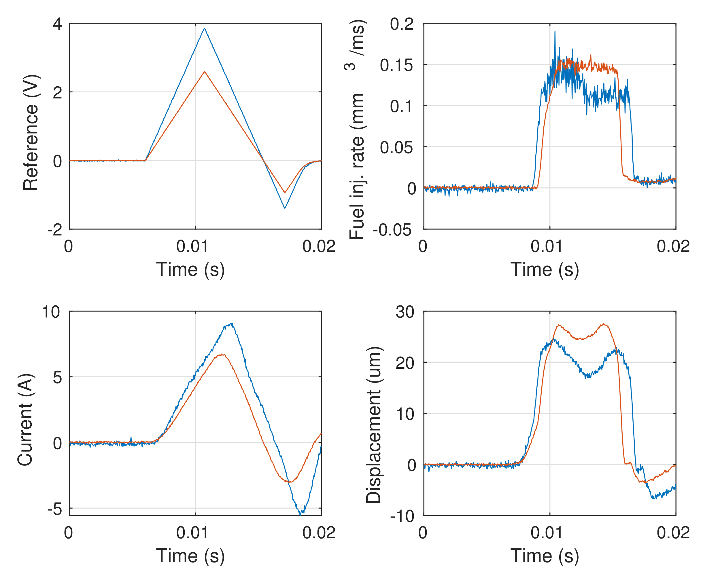
Figure 9 shows the comparison of triangular references with different amplitudes, and, in this case, different injection rates are achieved. A similar behavior is obtained with a longer pulse width,
ms, as shown in
Figure 10.


