1. Introduction
Essential tremor (ET) disorder is a neurological condition that causes the hands to shake rhythmically with a relatively constant frequency and variable amplitude [
1,
2]. The head, trunk, and voice may also be involved, but hand shaking is most prominent. Based on recorded statistics, ET has often been reported as the most common movement disorder, as almost 5% of a country’s population suffers from it [
3]. ET appears most frequently on the upper limbs and as a 4–12 Hz bilateral postural and kinetic tremor of the hands [
4], while no population has been proven to be immune to its development [
5]. The cause is not known, but it is often passed down from a parent to a child. Therefore, and as the frequency of ET is rising proportionally with age, the need for its suppression and treatment is vastly growing.
A number of methods have been introduced for the suppression and treatment of ET, as well as other related tremor disorders (e.g., Parkinson’s). They mostly include the following: (i) pharmacotherapy, i.e., medication therapy ranging from antiepileptics to antibiotics and bronchodilators; (ii) surgical treatments, with thalamotomy and Deep Brain Stimulation (DBS) reported also in cases of refractory ET [
5]. From the existing medication therapies for treating tremor, only a few agents have enough data available for their use to be widely recommended, while surgical interventions may be associated with more severe or persistent side effects.
During the last decade, the evolution of technology in an exponential pace has led to the investigation of alternative ways to suppress tremor. As a result, passive and active orthotic devices have been developed and manufactured, including exoskeletons capable of reducing different tremor characteristics (amplitude, frequency) on different joints of the upper limbs: fingers [
6,
7,
8], wrist [
9,
10], elbow [
11,
12,
13,
14,
15], as well as multiple upper-limb joints [
16,
17,
18]. Moreover, research-oriented and commercial solutions aim at ET suppression during tasks of everyday life such as food-consuming activities [
19,
20,
21] or handwriting [
22]. While all appliances presented potential in reducing tremor effects, their evaluation has only been performed in a controlled lab setting and they have not yet been tested on diagnosed patients. Moreover, some of the devices were characterized by rigid and bulky structures, with constrained applicability to task-specific applications, and limited bandwidth in terms of suppressing higher-frequency tremors. Furthermore, the functionality and ability of devices to avoid user injury under the effect of disturbances during daily use remains a critical matter [
23].
In this article, a soft exoskeletal glove for investigating the potential of utilizing Pneumatic Artificial Muscles (PAMs) for suppressing the hand tremor of ET patients is presented. ET has been specifically selected for this investigation, due to its increasing frequency of development in large parts of populations, as well as its relatively higher tremor frequencies and amplitudes [
2], which make it a challenging target. Moreover, PAMs have been selected as the actuation method for their similar properties with those of the organic muscle, combined with advantages such as the ability to provide high power outputs with light weights and inherent compliance [
24]. Moreover, PAMs meet the need for safety, simplicity, and lightness that human-robot interaction requires, which justifies its utilization in medical and biorobotic applications.
This article’s contributions stem from the design and the development of a hand exoskeleton that utilizes soft actuators for force-resistive applications. The exoskeleton’s design combines a lightweight approach with high efficiency and modularity, thus offering increased performance in various hand-motion scenarios. In this article, the hand tremor suppression potential by applying kinesthetic force on the user’s fingertips and on the metacarpal region is investigated. The presented approach, which extends the findings first shown in [
25], provides novel insights on the efficiency and effect of these design differentiations on suppressing ET tremor. Furthermore, an attempt is made to analyze the tremor properties for dual suppression methodology by simultaneously monitoring different arm points. Lastly, the efficiency of the proposed setup and derived protocol are extensively evaluated under different hand pose and motion scenarios performed by an ET-diagnosed volunteer. To the authors’ best knowledge, this is the first time that such a soft-actuated exoskeleton has been tested on an ET patient.
It must be noted that the force controller utilized in this article is based on a PID-based scheme. This conventional control algorithm has been documented for its efficiency in controlling PAM-enabled setups [
26,
27,
28,
29] and was selected as the most appropriate for the preliminary evaluation of the exoskeleton’s tremor-suppressing abilities. Work on synthesis and further improvement of the control properties under active force and compliance control is currently in progress.
The rest of the article is structured as follows. In
Section 2, the conceptual design of the hand exoskeleton is presented in detail, with highlighted overview of the implemented design alterations for investigating ET suppression on different regions of the lower arm.
Section 3 deals with the force control methodology incorporated for both investigated cases, while
Section 4 presents the setup prototype configurations and its utilized components. In
Section 5, the results acquired from the experimental evaluation of the investigated setups on an ET-diagnosed volunteer are provided and analyzed. Finally, concluding remarks and commentary regarding future work are given in
Section 6.
2. Conceptual Design
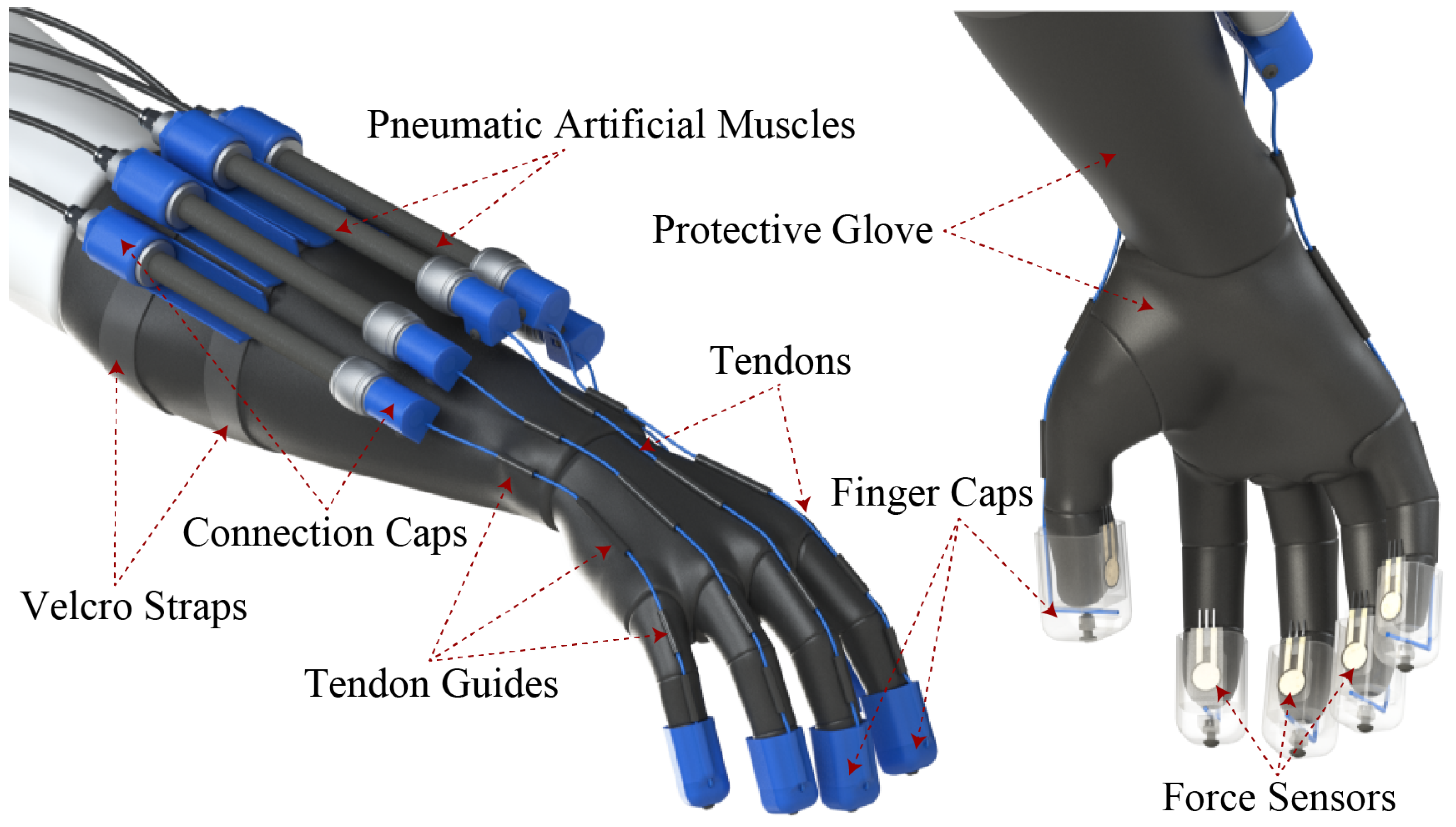
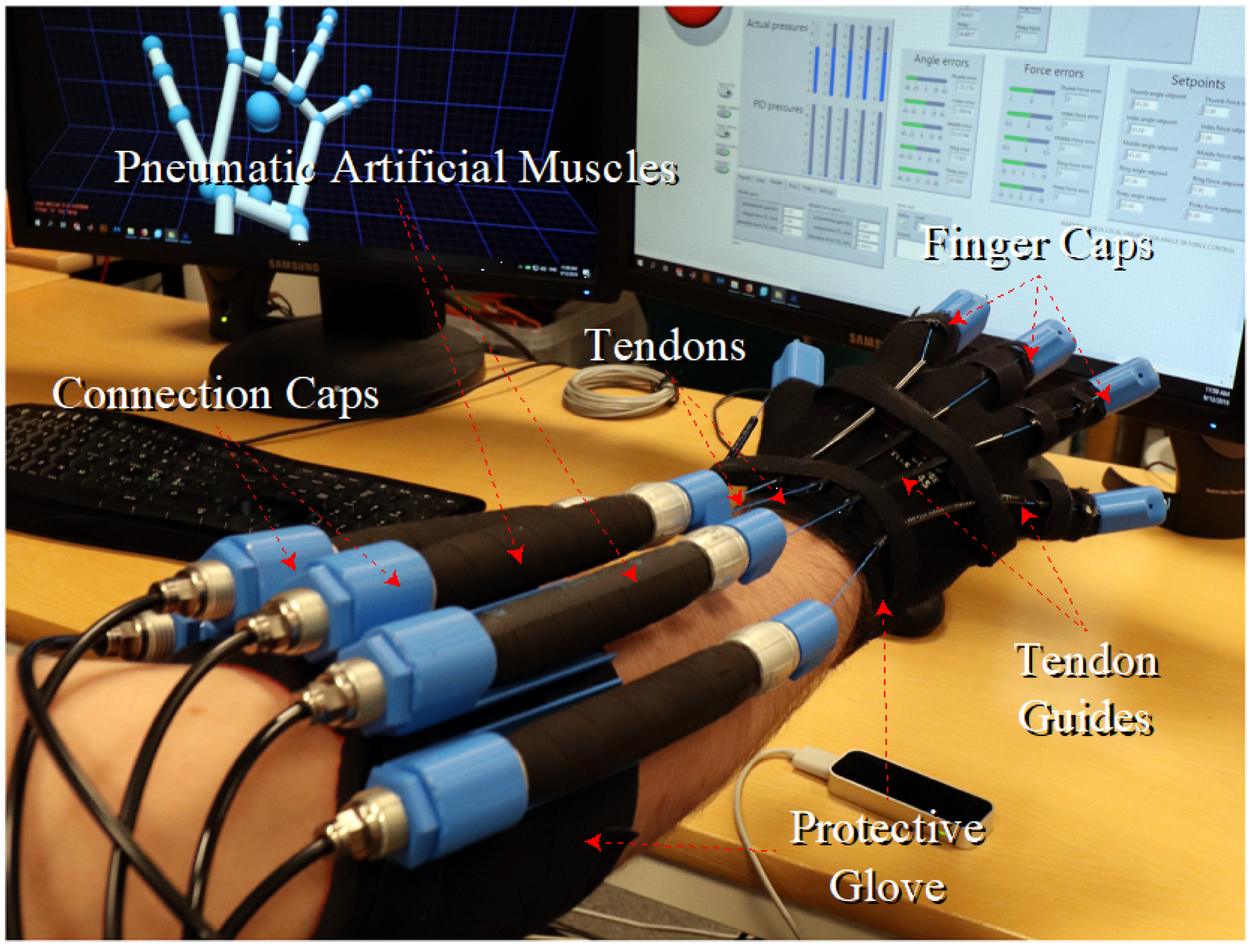
The structural challenge has been the development of an exoskeletal glove, which is capable of producing a resistive force on the fingertips while being manufactured with as few hard materials as possible and, thus, providing a light, comfortable, safe, low-construction-cost device. The base exoskeletal design (
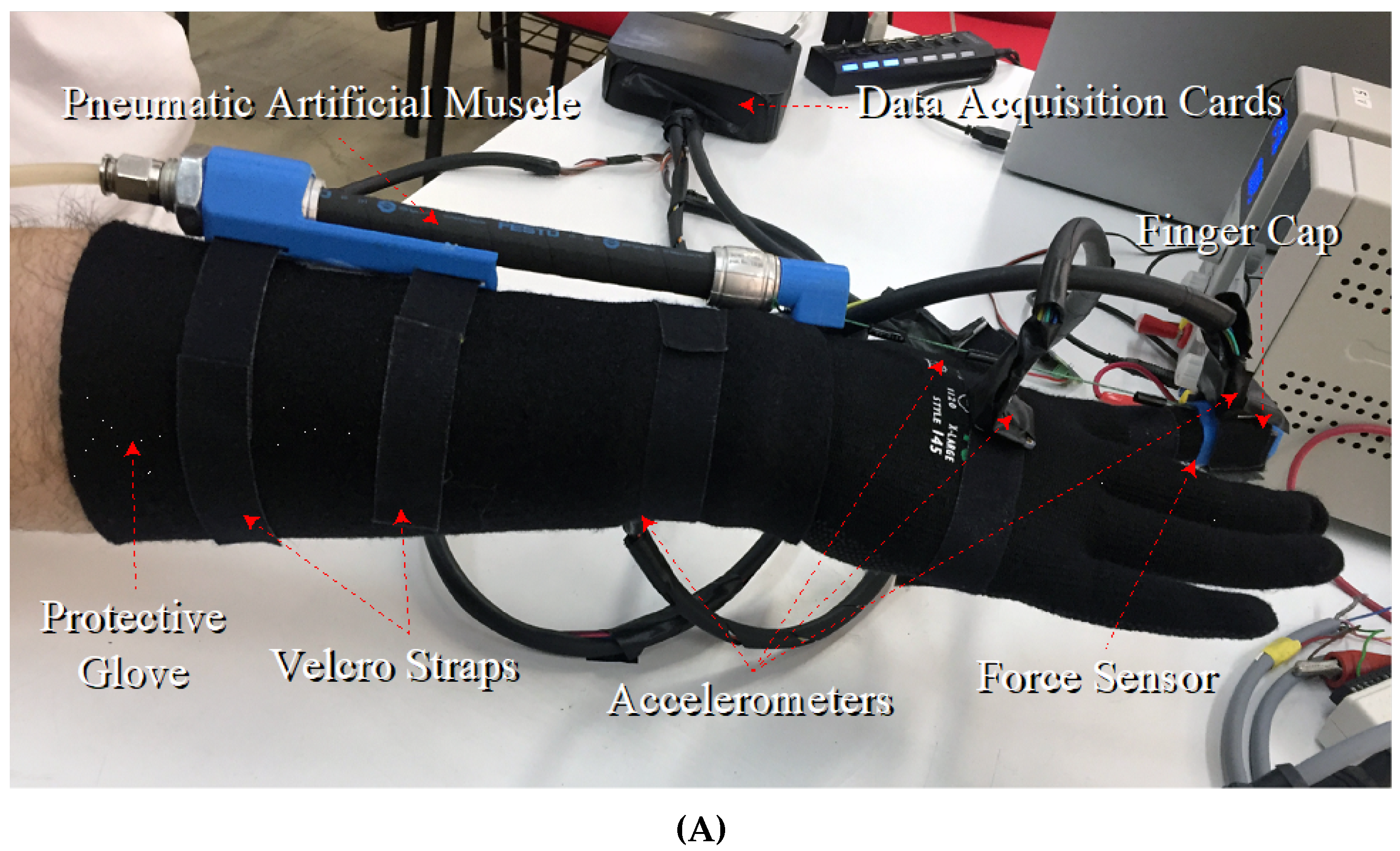
Figure 1) consists of a soft glove providing protection and attachment points on the forearm and hand, with 5 PAMs being strapped onto the forearm via connection caps, while tendons are adjusted between the PAMs and the caps that are placed on the user’s fingers. Force sensors are properly placed inside the finger caps at the point of contact with the fingertips. It must be noted that the base design was conceptually derived for applications requiring tactile and kinesthetic feedback, with the purpose of investigating its general use in physiotherapeutic applications, for interaction with objects in artificial reality environments etc.
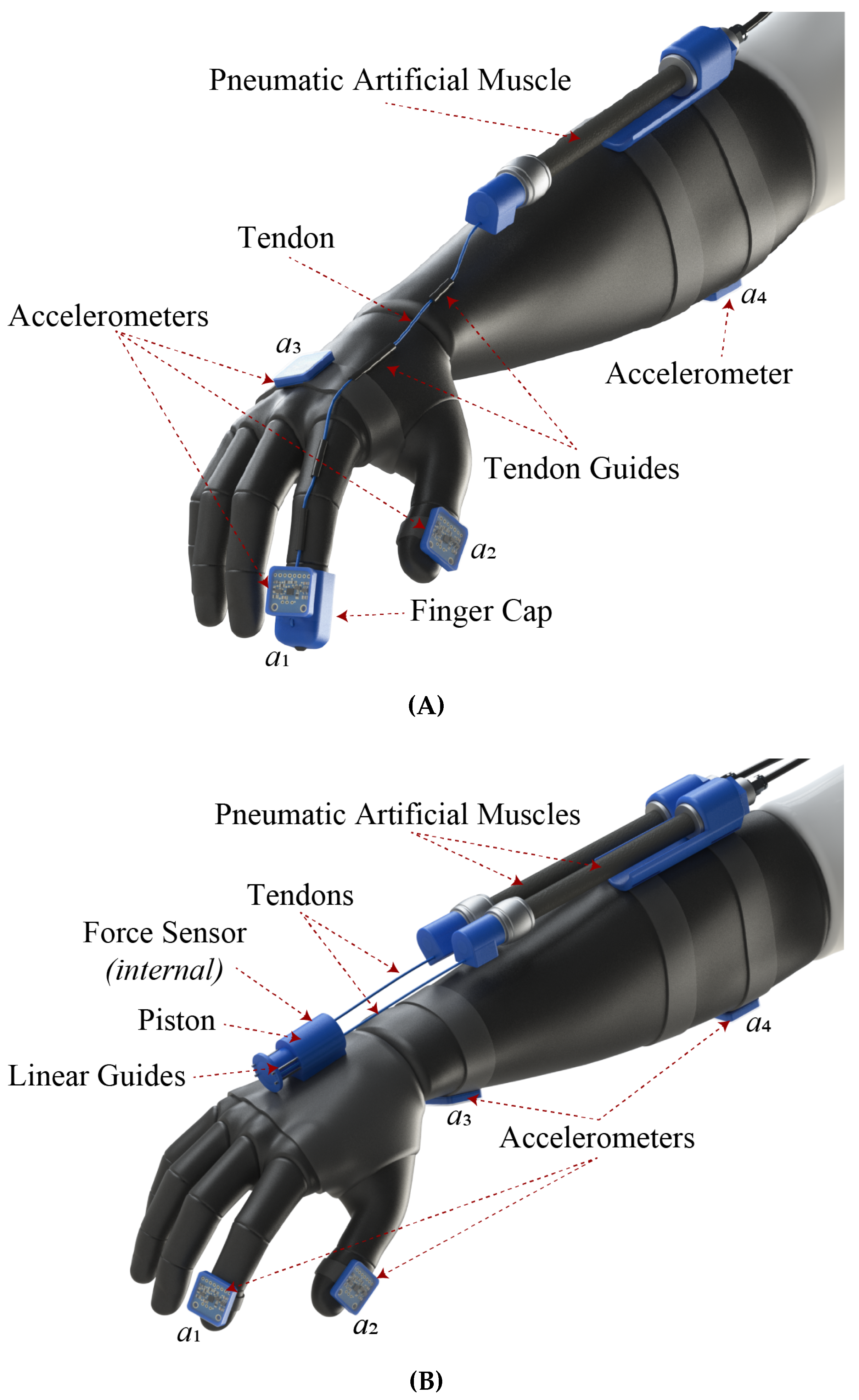
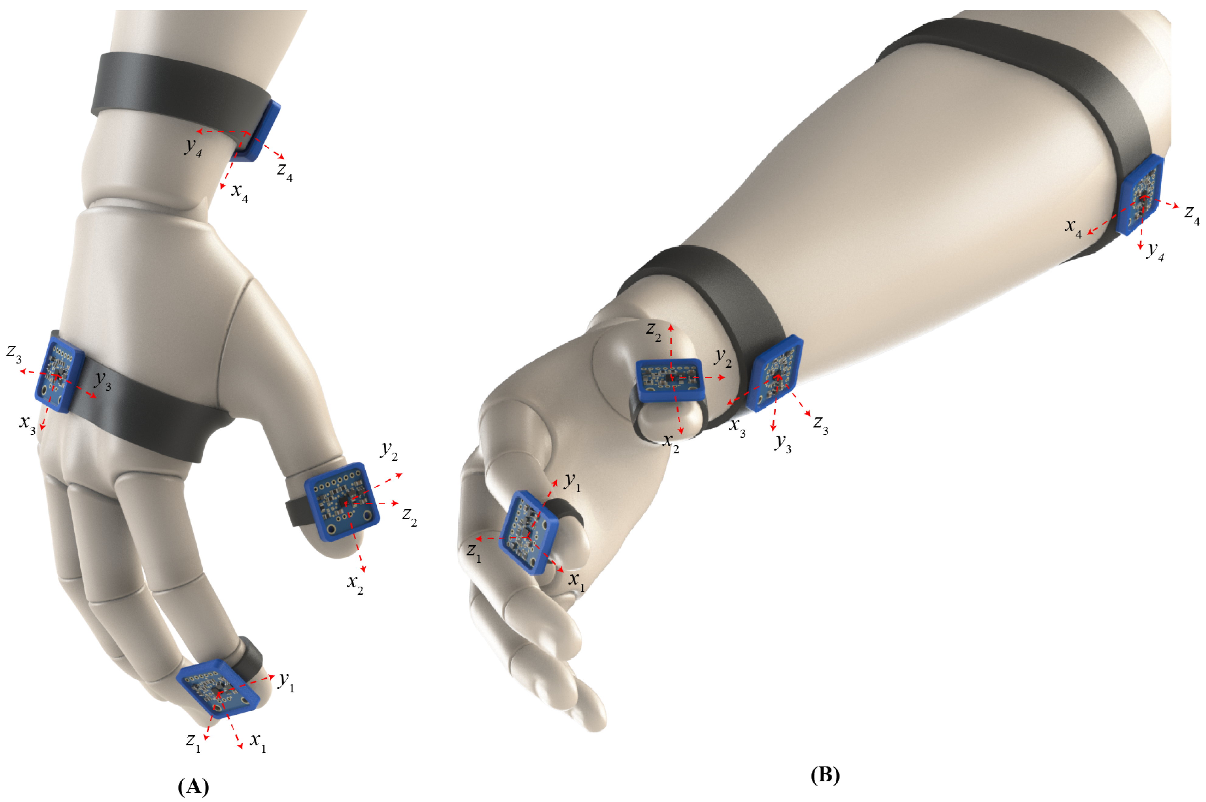
For the purposes of investigating the tremor suppression capabilities of the exoskeleton glove and, in parallel, test the modularity and reconfigurability of the proposed concept, two subconfigurations were derived. Specifically, to evaluate the effect of applying kinesthetic forces on different parts of the hand of a tremor-diagnosed volunteer, the design was focused on a modified iteration for force application on the index finger (
Figure 2A) and one with the resistive force applied on the metacarpal region (
Figure 2B), hereafter mentioned as iterations (A) and (B), respectively.
Iteration (A) utilizes a single PAM connected to the user’s index finger, in the same manner as described in
Figure 1. Four accelerometers
for
and
were properly placed on the distant phalanges of the index (
) and thumb (
) fingers, on the metacarpal (
), and on the upper forearm (
); their positioning was adjusted so as to be parallel to the respective skeletal frontal planes (
Figure 2A). This arrangement was selected with the goal of assessing the tremor behavior on different fingers and parts of the lower arm, during local kinesthetic force application to a single finger.
Iteration (B) is focused on assessing the ET alterations on different lower-arm regions when resistive force is applied to the user’s metacarpal area. To this goal, two PAMs were connected via tendons to a cylinder mechanism, which was firmly adjusted to the protective glove. The selection of the dual actuation was deemed necessary for ensuring symmetrical force application on the cylinder mechanism and increasing the system’s bandwidth for handling the wrist’s higher reactive forces. Specifically, the cylinder bears an internally a spring-based piston, which holds a force sensor on the piston’s tip. Small metallic guide rods ensure the linear motion of the piston and the transfer of the pulling force on the metacarpal. This mechanism was selected for focusing and measuring the kinesthetic effect on the metacarpal region and avoiding the direct connection and subsequent effect on the fingers. Similarly, four, three-axis accelerometers
were placed on the distant phalanges of the index (
) and thumb (
) fingers as well as on the lower (
) and upper (
) forearm, as depicted in
Figure 2B.
3. Force Control Methodology
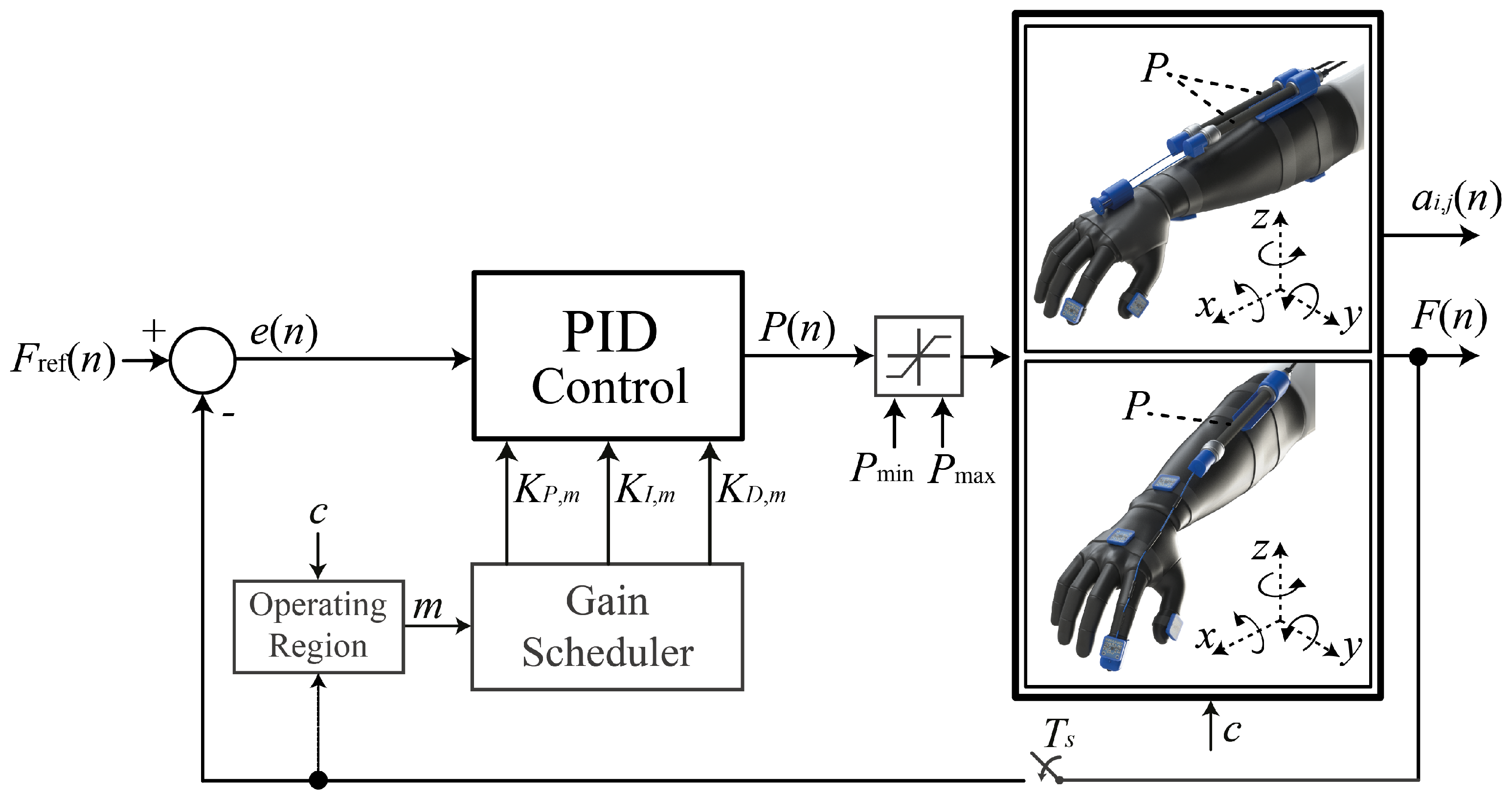
For the design iterations (A) and (B) presented in the previous section, a force control scheme was synthesized for properly adjusting the pressure P of air fed into the muscles and for controlling the applied resisting force F on the target region. For the preliminary evaluation of the exoskeleton’s tremor-suppressing abilities and given that both iterations were handled as Single-Input Single-Output (SISO) systems, a PID-based algorithm was selected as the most appropriate for this task due to its feasibility and easy implementation. Furthermore, PID provides a reliable solution when the system’s parameters cannot be precisely estimated. Synthesis and implementation of model-based algorithms for further improving the control properties under active force and compliance control is considered part of future work.
The scheme presented in
Figure 3, features the feedback control action
, which utilizes the weighted sum of three control parameters. Under the assumption of a sampling process with a sampling period
∈
, at sample
n∈
, the PID algorithm is mathematically formulated as in
where
,
, and
are the proportional, integral, and derivative gains, respectively. By an appropriate selection of the aforementioned control parameters, the controller’s goal is to adjust the manipulated variable
P(
t) and achieve minimization of the process’ error signal
, or equivalence between the set-point force
and measured value
F.
The PAMs utilized in iterations (A) and (B) consist of a double helix aramid netting at a predetermined angle, covered by a neoprene threaded coating, thus, resulting in a tubelike formation. This dual-material formation is characterized by high nonlinearities that are presented below [
30]:
The viscoelastic properties of the neoprene wrapping;
The friction phenomena between the aramid threads of the double helix weaving and the neoprene coating as well as the relative motion of the aramid threads themselves;
The noncylindrical deformation of the tube edges during the PAM’s inflation.
All the aforementioned properties result in complex hysteretic behavior during the PAM’s operation. Furthermore, nonlinearities are also induced via the elastic components of the glove and soft tissue of the user’s arm that can affect the overall performance of the setup. For the purposes of this investigation and given the Velcro-enabled muscle placement, the custom glove fitting, and the generally limited applied forces, the effect of such nonlinearities is assumed negligible, while their characterization and modeling is part of future iterations.
To counteract the PAM’s intense nonlinearities, a gain scheduler is appropriately incorporated in the PID control structure, which has the ability to alter the control parameters according to the reference force level denoted by the signal
c; it is used for switching between the reference and control values set for iterations (A) and (B), and according to the active region of operation, specified by the selected force
F. The operating regions are defined during experimentation. The applied force was divided into smaller regions depending on the reference force
. Different points were defined experimentally via the Ziegler–Nichols frequency response method applied to each operating region and followed by additional fine-tuning through extensive experimental trials. In this case, an additional switching signal
m∈
is introduced that rules the switching values of the previously constant gains, as in the sequel:
where
M∈
is the maximum number of operating regions. The discrete equation of the implemented gain-scheduled PID using the Backward Euler formula for the integration and derivative filter is presented in (3):
Based on operational safety guidelines and the desirable control attributes, constraints are posed on the controllers’ output
P(
n) and set-point value
, by setting minimum and maximum limits as specified in (4):
5. Experimental Evaluation
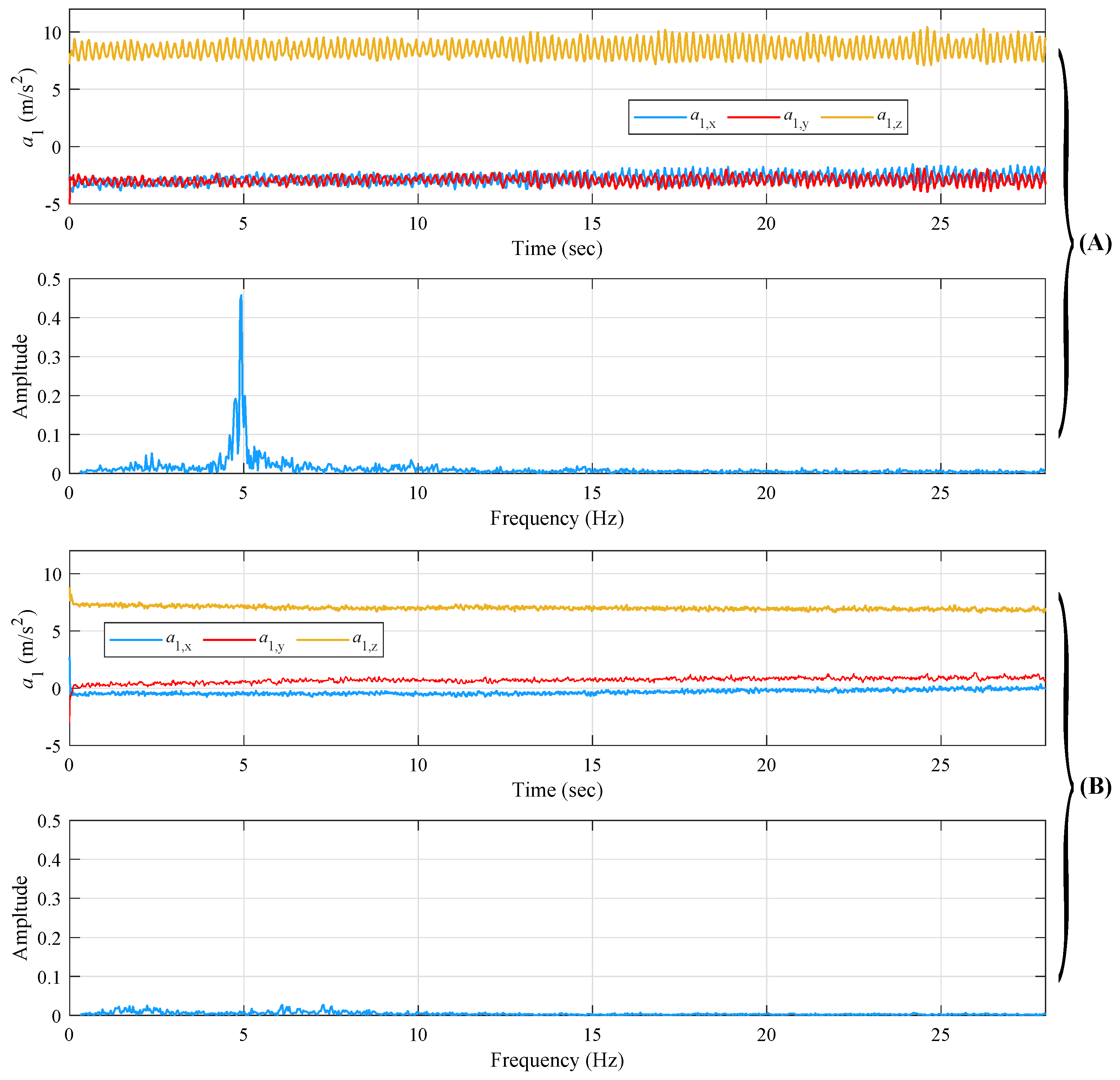
The accelerometer data extracted from the signal acquisition device include the signals of acceleration in
axes as a function of time
t and are utilized to calculate the frequency spectrum of amplitude of the resultant acceleration vector of the measured signal for the extraction of the dominant tremor frequency. Indicatively,
Figure 8A,B present the data acquired via (a) an ET-diagnosed patient and (b) a volunteer without tremor evidence. The acceleration measurements refer to the extended arm position for the index
. It is noted that for the amplitude spectrum plots in
Figure 8, a high-pass filter was applied with a cutoff frequency of
Hz to avoid the DC artifact at 0 Hz.
From
Figure 8A, the main extracted ET frequency for the specific measurement is easily distinguished and observed close to
Hz, while the amplitude is
. From
Figure 8B, it is easily distinct how the volunteer keeps his arm extended without shaking significantly. However, as shown by the spectral diagrams, some small amplitude frequency peaks appear, the causes of which are attributed to the measurement noise from the accelerometer. Finally, the nontrembling volunteer’s tremor frequency shows a significantly smaller amplitude in comparison to the tremor-diagnosed one, as expected.
For experimentally evaluating the ET suppression capabilities of the proposed prototypes (A) and (B), a 53-year-old, male, right-handed volunteer, diagnosed with chronic ET of 45 years, was selected. As noted in
Table 1, although the volunteer receives medication for his condition, during the experiment procedure, he had not taken any pills in the last 12 h. Prior to commencement of the presented experimental study, the volunteer was informed verbally and in writing about the purpose of the study, the experimental protocol, and his right to cancel his participation at any time.
Initially, and before beginning the basic experimental procedure, we extracted the dominant tremor frequency of the ET participant’s hand in 4 different hand positions/motions. In
Table 2, the dominant tremor frequency observed from the participant during different hand motions is shown. The frequency from each of the 4 accelerometers of the signal acquisition device is defined as
, where
for the accelerometer’s placement on the index, the thumb, the metacarpal, and the forearm, respectively, and
for the hand at resting position, at postural position, performing free motion, and performing motion while holding a spherical object, respectively.
All following experimental sequences began by mounting the setup on the volunteer’s right hand, followed by the proper adjustment of the tendons while the volunteer’s hand was in a straight position and the PAMs were fully contracted at the maximum permissible pressure. This adjustment ensured that the glove would not forcefully hyperextend the volunteer’s fingers at any point, thus eliminating the potential risk of inducing extreme joint movements and injuries.
Initially, all experimental sequences involving the presented prototypes were executed under open-loop control of the kinesthetic force, for evaluating the setups’ force limits and recording the effect of increasing the localized kinesthetic force on the volunteer’s ET measurements from the four utilized accelerometers. Following the open-loop experiments, closed loop sequences involving the PID control scheme presented in
Section 3 were performed to evaluate the controller’s efficiency in tracking the setpoint value and the overall effect on the volunteer’s ET characteristics.
The aggregated results regarding maximum ET frequency and amplitude reduction rates (%) for iterations (A) and (B), under open-loop (OL) and closed-loop (CL) evaluations, are provided in
Table 3,
Table 4,
Table 5,
Table 6,
Table 7,
Table 8,
Table 9,
Table 10 and
Table 11 and are discussed in detail in the next subsections. The naming utilized in the same Table involves the following:
Iteration (A): the respective frequencies and amplitudes of the distant phalanges of the index ( and ) and thumb ( and ) fingers, the metacarpal ( and ), and the upper forearm ( and ).
Iteration (B): the respective frequencies and amplitudes of the distant phalanges of the index ( and ) and thumb ( and ) fingers, the lower forearm ( and ), and the upper forearm ( and ).
Table 3.
ET frequency reduction rates during the Prototype (A) Open-Loop evaluation.
Table 3.
ET frequency reduction rates during the Prototype (A) Open-Loop evaluation.
| Exp. | | | | | | | | | | | | | | | | |
|---|
| 1 | 65 | 47 | 42 | 51 | 35 | 47 | 42 | 41 | 47 | 45 | 75 | 56 | 47 | 47 | 77 | 57 |
| 2 | 38 | 40 | 52 | 43 | 26 | 64 | 38 | 43 | 69 | 63 | 78 | 70 | 67 | 62 | 0 | 64 |
| 3 | 17 | 20 | 27 | 21 | 17 | 21 | 30 | 23 | 20 | 30 | 77 | 42 | 20 | 20 | 57 | 32 |
| Av. | 35 | 36 | 40 | 38 | 26 | 44 | 33 | 36 | 45 | 46 | 77 | 56 | 45 | 50 | 45 | 51 |
Table 4.
ET amplitude reduction rates during the Prototype (A) Open-Loop evaluation.
Table 4.
ET amplitude reduction rates during the Prototype (A) Open-Loop evaluation.
| Exp. | | | | | | | | | | | | | | | | |
|---|
| 1 | 94 | 78 | 53 | 75 | 99 | 29 | 36 | 55 | 20 | 11 | 10 | 14 | 13 | 7 | 6 | 9 |
| 2 | 30 | 86 | 54 | 57 | 94 | 66 | 53 | 71 | 79 | 28 | 10 | 39 | 57 | 21 | 6 | 28 |
| 3 | 58 | 46 | 46 | 50 | 34 | 63 | 1 | 33 | 52 | 19 | 1 | 24 | -42 | 11 | 1 | -10 |
| Av. | 61 | 70 | 51 | 74 | 76 | 53 | 30 | 53 | 50 | 19 | 7 | 26 | 35 | 13 | 4 | 12 |
Table 5.
PID parameters for the Prototype (A) Closed-Loop control scenario.
Table 5.
PID parameters for the Prototype (A) Closed-Loop control scenario.
| m | Operating Regions [N] | | | |
|---|
| 1 | | 1.00 | 0.10 | 0.02 |
| 2 | | 1.80 | 0.32 | 0.02 |
| 3 | | 2.40 | 0.40 | 0.12 |
| 4 | | 1.56 | 0.14 | 0.05 |
Table 6.
ET frequency reduction rates during the Prototype (A) Closed-Loop evaluation.
Table 6.
ET frequency reduction rates during the Prototype (A) Closed-Loop evaluation.
| Exp. | | | | | | | | | | | | | | | | |
|---|
| 1 | 38 | 44 | 22 | 35 | 40 | 73 | 50 | 54 | 72 | 48 | 78 | 66 | 70 | 40 | 59 | 56 |
| 2 | 38 | 51 | 37 | 42 | 21 | 68 | 44 | 44 | 73 | 62 | 0 | 45 | 74 | 63 | 72 | 70 |
| 3 | 32 | 45 | 26 | 34 | 28 | 53 | 34 | 38 | 68 | 47 | 0 | 38 | 56 | −65 | −77 | −29 |
| Av. | 36 | 47 | 28 | 37 | 30 | 65 | 43 | 45 | 71 | 52 | 26 | 50 | 67 | 51 | 44 | 63 |
Table 7.
ET amplitude reduction rates during the Prototype (A) Open-Loop evaluation.
Table 7.
ET amplitude reduction rates during the Prototype (A) Open-Loop evaluation.
| Exp. | | | | | | | | | | | | | | | | |
|---|
| 1 | 88 | 61 | 58 | 62 | 23 | 74 | 42 | 46 | 25 | 27 | 20 | 24 | 33 | 31 | 9 | 24 |
| 2 | 84 | 63 | 39 | 62 | 75 | 39 | 33 | 49 | 37 | 49 | 20 | 35 | 36 | 47 | 23 | 35 |
| 3 | 91 | 79 | 55 | 75 | 50 | 47 | 23 | 40 | −3 | −93 | −7 | −34 | −4 | −83 | −23 | −37 |
| Av. | 88 | 64 | 51 | 66 | 49 | 53 | 33 | 45 | 43 | 38 | 20 | 29 | 34 | 39 | 16 | 29 |
Table 8.
ET frequency reduction rates during the Prototype (B) Open-Loop evaluation.
Table 8.
ET frequency reduction rates during the Prototype (B) Open-Loop evaluation.
| Exp. | | | | | | | | | | | | | | | | |
|---|
| 1 | 28 | 15 | 35 | 26 | 35 | 22 | 28 | 28 | 23 | 46 | 56 | 42 | 40 | 40 | 70 | 50 |
Table 9.
ET amplitude reduction rates during the Prototype (B) Open-Loop evaluation.
Table 9.
ET amplitude reduction rates during the Prototype (B) Open-Loop evaluation.
| Exp. | | | | | | | | | | | | | | | | |
|---|
| 1 | 70 | 62 | 31 | 56 | 92 | 27 | 41 | 53 | 73 | 76 | 8 | 52 | 52 | 73 | 7 | 44 |
Table 10.
PID parameters for the Prototype (B) Closed-Loop control scenario.
Table 10.
PID parameters for the Prototype (B) Closed-Loop control scenario.
| m | Operating Regions [N] | | | |
|---|
| 1 | | 1.20 | 0.10 | 0.02 |
| 2 | | 1.40 | 0.10 | 0.02 |
| 3 | | 1.65 | 0.22 | 0.07 |
| 4 | | 1.93 | 0.10 | 0.07 |
| 5 | | 1.70 | 0.20 | 0.05 |
Table 11.
ET frequency reduction rates during the Prototype (B) Closed-Loop evaluation.
Table 11.
ET frequency reduction rates during the Prototype (B) Closed-Loop evaluation.
| Exp. | | | | | | | | | | | | | | | | |
|---|
| 1 | 33 | 42 | 48 | 41 | 44 | 65 | 66 | 58 | 56 | 67 | 77 | 67 | 78 | 70 | 58 | 69 |
| 2 | 38 | 51 | 35 | 41 | 24 | 64 | 62 | 50 | 14 | 40 | 73 | 42 | 22 | 41 | 76 | 46 |
| Av. | 35 | 46 | 41 | 41 | 34 | 64 | 64 | 54 | 35 | 53 | 75 | 54 | 50 | 55 | 67 | 57 |
5.1. Prototype (A) Open-Loop Evaluation
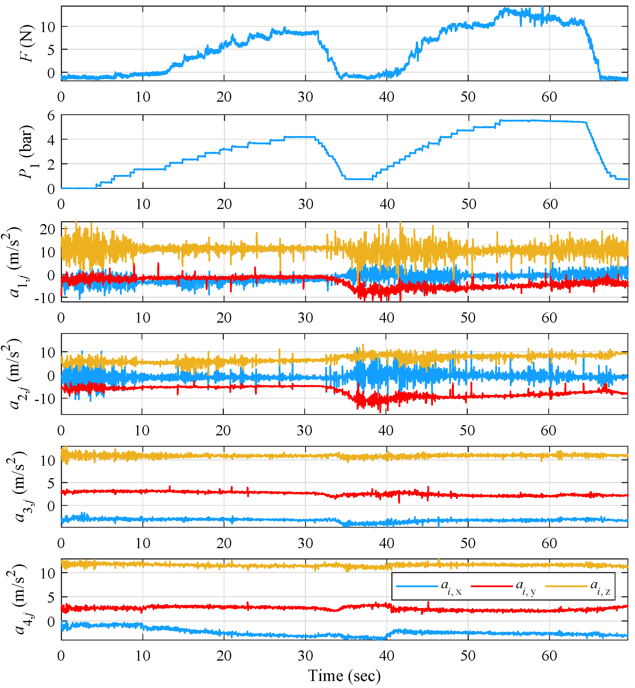
The open-loop evaluation of iteration (A) and the effect of applying resisting force on the index finger was performed via three experiments examining ET suppression for variable increases in pressure, while the volunteer’s hand was in an extended pose. The results concerning the applied pressure
P, the resulting force
F, and the measurements from the four three-axis accelerometers are presented in
Figure 9,
Figure 10 and
Figure 11.
For the first open-loop experimental evaluation of iteration (A) and by observing
Figure 9, the pressure follows an increasing and decreasing trend, reaching a maximum of
bar, while the force is alternating between 0 and 15 N. The documented minor force alterations were also caused by minor involuntary reactions of the volunteer’s hand during the pressure increase.
At time intervals when no force is exercised, i.e., 0–12 s and 32–41 s, tremor is clearly visible in the volunteer’s index and thumb measurements. Then, during time intervals 26–32 s and 54–64 s, where the applied
F starts to stabilize, a gradual decrease in ET amplitude and frequency is observed for all measurement points, as shown in
Table 3 for the (A)-(OL) case. The maximal reduction was recorded on the metacarpal at 70% ET frequency with the respective reduction on the index straying at the lower level of 51%, while ET amplitude was reduced at a maximal 75% on the index finger. Therefore, although the force from the PAM is exerted on the index finger, it indirectly affects the other parts of the lower arm in stabilizing their tremor. Such an effect could originate from the distribution of the force coefficient acting coincidentally to the bone structure, as well as the tendon contact forces through the guides.
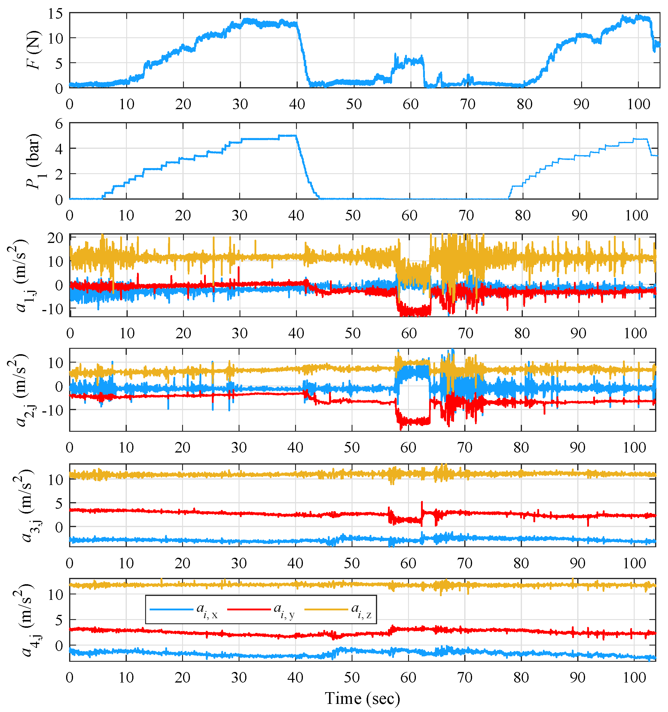
The 2nd experiment—in addition to verifying repeatability—aims to emphasize the voluntary patient-induced occurrence of tremor as observed between 56–62 s. During this time, the patient bends the wrist downwards, enhancing the amplitude and frequency of tremor, as seen in
Figure 10, resulting in a large decrease in ET amplitude of the index and thumb and an observable decrease on the metacarpal and forearm. Furthermore, the sharp and large increase in ET amplitude on the index and thumb, as well as the smaller but visible increase in the amplitude of the oscillation of the metacarpal as a result of the voluntary movement, denote the capability of the volunteer to activate/increase his tremor by performing short, voluntary movements, without necessarily tiring his hand out.
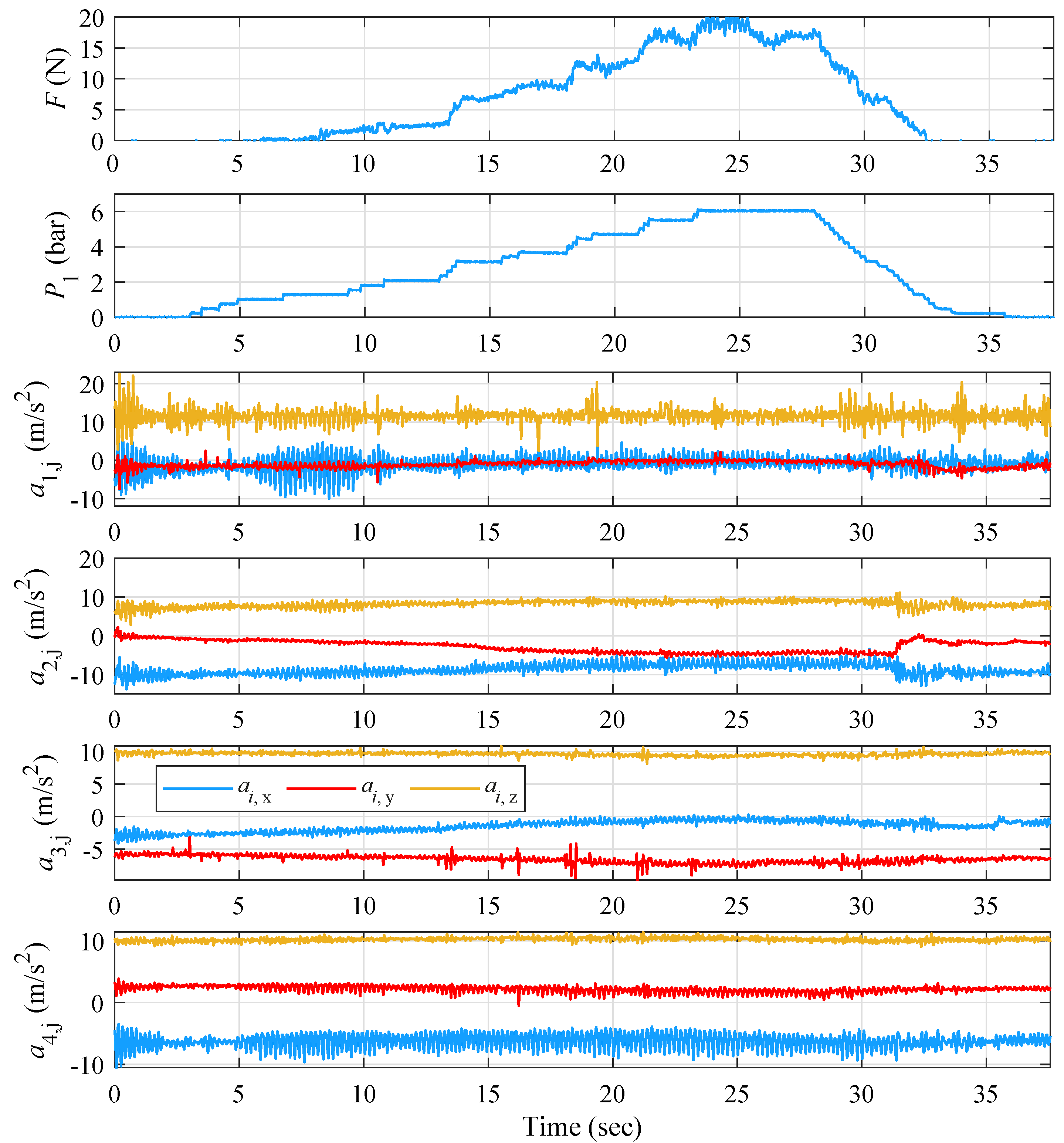
In the next experiment,
P was increased and held steady at its maximum value, i.e., 6 bar. As shown in
Figure 11,
F is not stabilized around any point for a period longer than 2 s. At the time between 12 and 28 s, when the amplitude and frequency of the tremor on the two fingers is significantly reduced, increased tremor is noticeable on the forearm. As observed at the time of the experiment, a muscle at the top edge of the forearm started to pulsate. In more detail,
and
increase sharply from the 5th s when
F starts to rise, and weaken from the 32nd s when
F begins to decrease, denoting a “tremor translation” behavior from the fingers to the rest of the hand.
By observing
Table 3, the largest decrease in
is seen on the z axis with an average of 40%, slightly higher than the other two axes. The largest decrease at the x and y axes appears in experiment 1 and amounts to 65 and 47%, respectively; in experiment 2,
reaches its maximal reduction rate with 52%. The largest rate of frequency reduction on the index is observed in experiment 1 with 51%. On the thumb, the largest frequency reduction is achieved on the y axis with 44% and mainly in experiment 2 with 64%. On the metacarpal, the maximum reduction is observed on the z axis with 77% with a significant difference from the other two axes. Experiment 2 has the optimum rate of tremor frequency reduction with 70%. On the forearm, the maximum ET frequency decrease is detected on the y axis with 50%, but close to the other two axes. Similarly to the metacarpal, experiment 2 provides the optimal frequency reduction rate of 62%.
Looking at
Table 4, the largest decrease in ET amplitude on the index is observed at the y axis with an average percentage of 70%. The largest decrease on the x axis is observed in experiment 1 and amounts to 94%, and on the y and z axes in experiment 2 with 86% and 54%, respectively. The largest rate of reduction on the index is found in experiment 1 with 75%. On the thumb, the greatest reduction in tremor amplitude lies on the x axis with 76%, with significant differences to the other two axes. The largest decrease on the x axis is observed in experiment 1 and amounts to the high 99%. The largest decrease on the thumb is found in experiment 2 with 71%. On the metacarpal area, the maximum reduction on the x axis is 50%, while the reduction rates on the y and z axes are low. The largest tremor amplitude decrease appears in experiment 2 and amounts to 79% on the x axis. On the forearm, the maximum decrease is detected on the x axis and reaches up to 35%. The greatest reduction rate is observed in experiment 2 with 57% on the x axis. It should be noted that for the export of the mean reduction rates on the forearm, the percentages of the
experiment were not taken into account, as there are increased rates on the x axis. Regarding this experiment, and especially for the forearm region, from
Table 4, an increase in ET is noticeable on the x axis by 42%, confirming the ”tremor translation“ observation.
5.2. Prototype (A) Closed-Loop Evaluation
The closed-loop evaluation of iteration (A) was initiated with a set-point reference force value set at approximately 6 N, as obtained from (A)-(OL) as a suitable force level for effective ET reduction, while the volunteer’s hand was in the relaxed state. The gain scheduler’s control parameters
,
, and
were tuned via the Ziegler–Nichols frequency response method applied on each operating region and followed by additional fine-tuning through extensive experimental trials. The aforementioned parameters are presented in
Table 5.
From the results presented in
Figure 12, it is observable that the index and thumb are initially characterized by a high ET amplitude and frequency before enabling the controller. A significant decrease in index ET amplitude can be observed in all measurement points for the time interval where the force approaches the reference signal. A similar decrease in both amplitude and frequency is also observed on the thumb. On the metacarpal region and at the upper forearm, a similar behavior is noticed, with an important decrease in ET amplitude and frequency when stabilizing the force around the reference signal. Then, the ET symptoms enhance again when disabling the controller at approximately
s. In addition, the responses produced via the PID scheme are characterized by smooth control effort alterations, as the gain scheduler switches between neighboring regions, which results in very small variations from the reference signal.
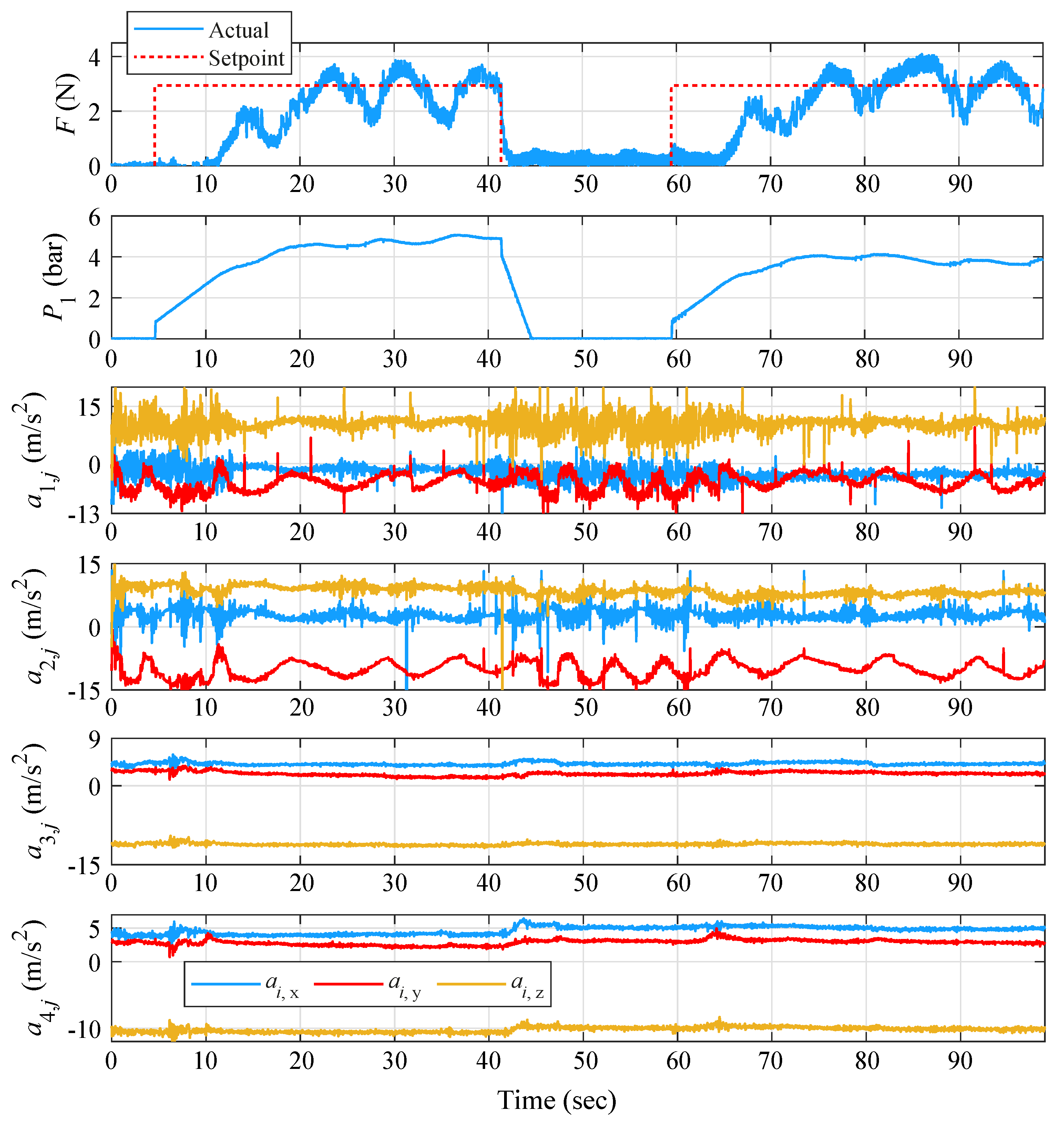
Two additional experiments were performed while in closed-loop operation, where the controller was activated in the presence of ET, the volunteer was asked to bend his fingers until they touched a spherical object, and then to return them to their original position.
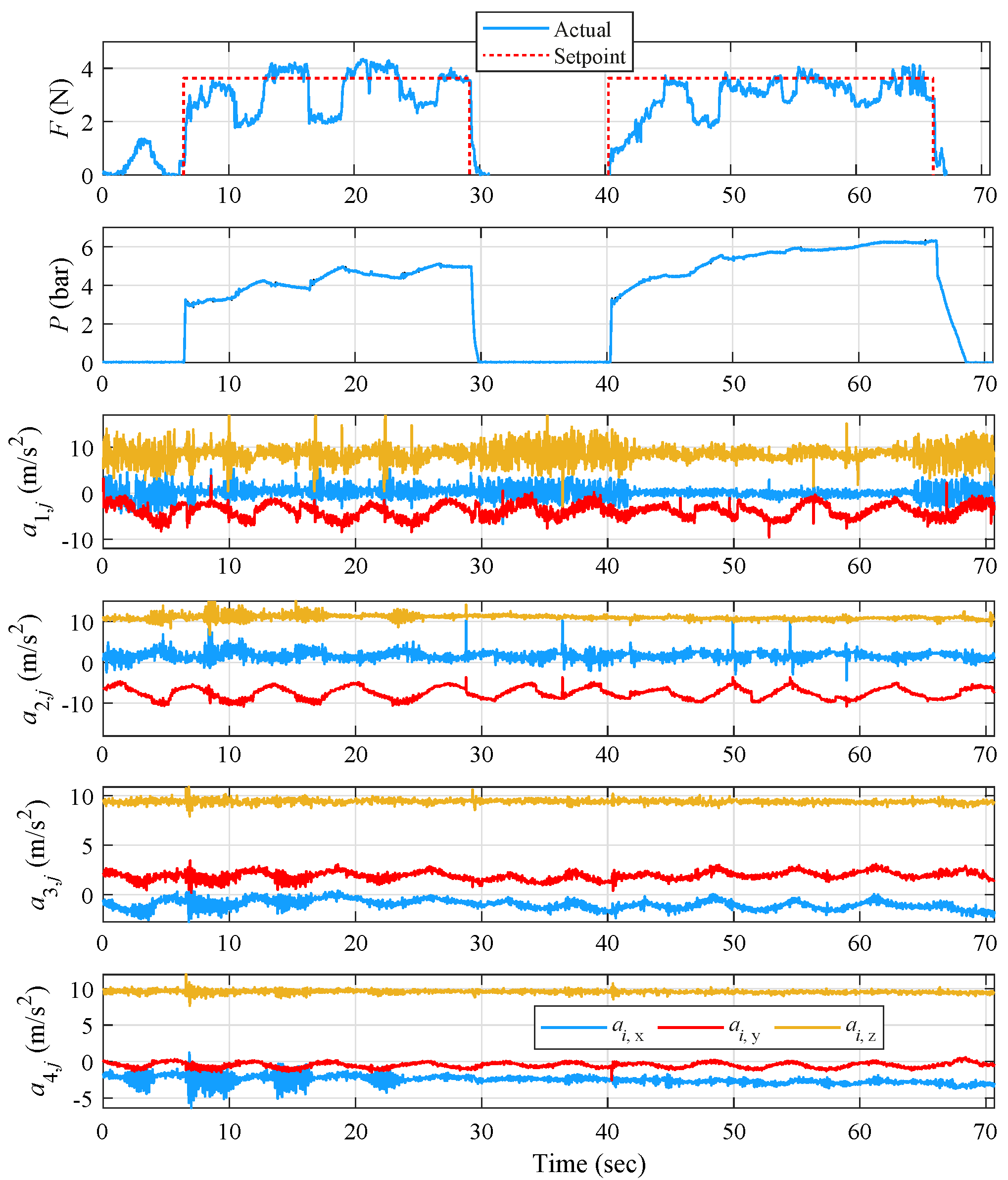
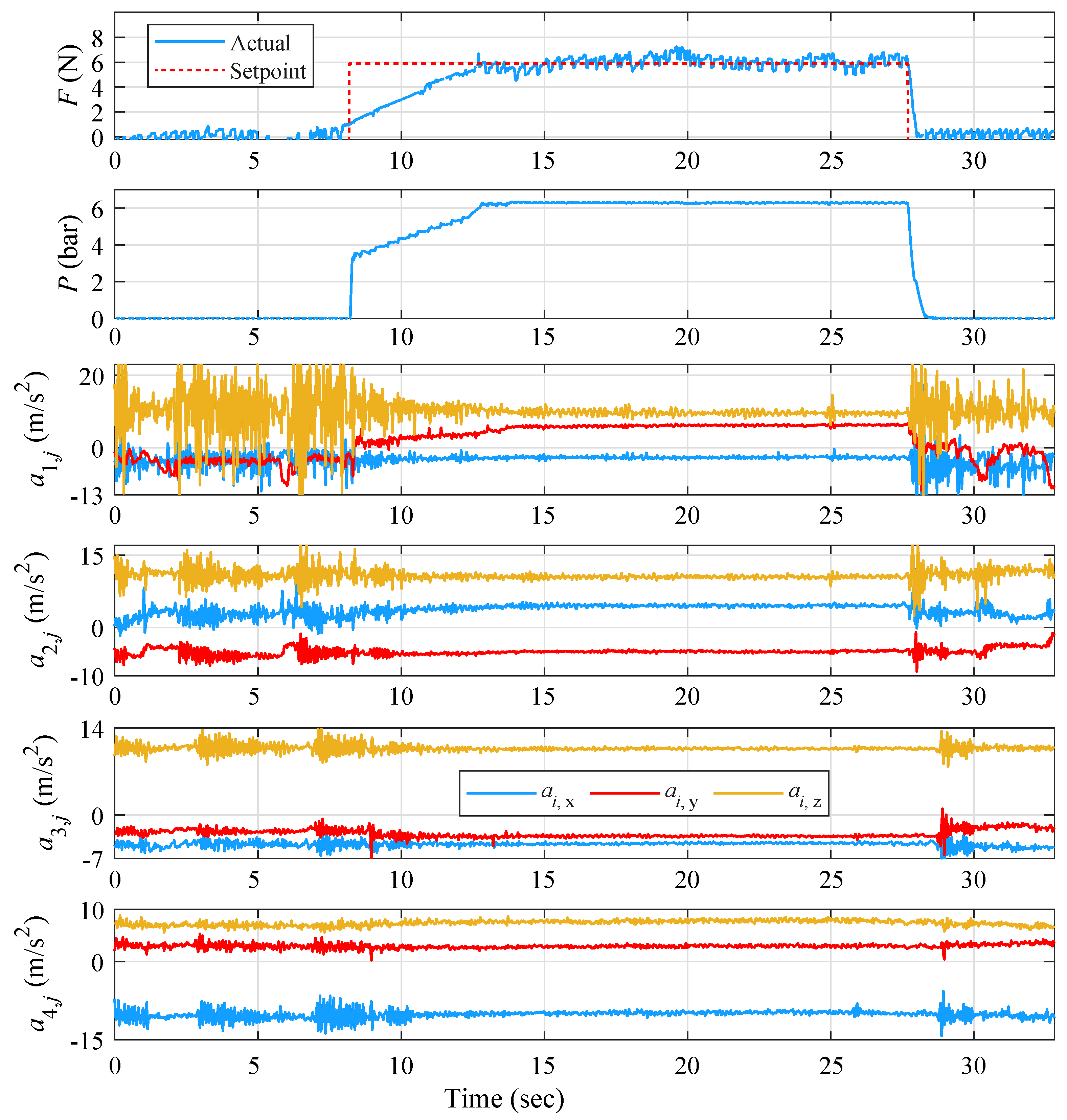
From the results presented in
Figure 13, it is clearly observed that until the first 5 s, the controller is turned off. The controller is activated from 5–41 s and from 60 s to the end of the trial. For the total duration of the experiment and throughout the volunteer’s motion, the controller was tuned to provide smooth behavior with absence of abrupt alterations in pressure, although characterized by a slower convergence of about 4 sec per activation. At the activation intervals of 5–41 s and 60–95 s, where the controller attempts to track the force set-point despite the volunteer’s movements, a noticeable reduction in the ET amplitude and frequency during the bending of the hand can be observed for all four measurement points, demonstrating the efficiency of the proposed solution. The overall force remains in small values ranging from approx. 1 to 4 N, which do not significantly constrain the volunteer’s finger mobility. Interestingly, at the metacarpal and upper forearm, the ET amplitude is not increased after the controller is deactivated at 41 s. Possibly, a “stimulus” from the setup was enough to reduce the tremor’s amplitude in those regions and continue this effect until the next occurrence.
The 3rd experiment describes the behavior of the suppression system when applying a more “counteractive” controller with increased proportional gain
(3–33 s) and a less “reactive” one with reduced
(49–93 s). It is noted that the
and
gains are tuned to responses that were satisfied by the convergence and oscillation characteristics, and therefore remain constant. As can be observed from
and
diagrams in
Figure 14 and during the first controller activation, in order for
F on the index to approach the reference signal set at
N, the pressure actuation is more direct and steep than during the second activation. So, even though the force reaches the setpoint faster than the first activation, the steady-state error is substantially greater.
Simultaneously, for both the controller activation periods and the tremor suppression on index and thumb fingers, the tremor amplitude on the metacarpal area and on the forearm increased. This “tremor translation” phenomenon was met once again for the open-loop case of iteration A.
According to
Table 6, the largest average decrease in
appears on the y axis with 47%, while the x and z axes have average values of 36 and 28%, respectively. The largest decrease on the x axis appears in experiments 1 and 2 with 38%, and on the y and z axes in experiment 2 with 51% and 37%, respectively. The largest reduction rate on the index is met in experiment 2 with a rate of 42%. On the thumb, as on the index, the largest frequency reduction is achieved on the y axis with 65%, but this time with a significant difference to the other two axes. The largest ET frequency reduction rate is observed in experiment 1 on the y axis and amounts to 73%. At the metacarpal area, the maximum reduction is observed on the x axis with 71%. The largest decrease on the x axis is observed in experiment 2 with 73%, while experiment 1 follows closely with 72%. On the y axis, the maximum reduction percentage is found in experiment 2 with 62% and on the z axis again in the 2nd experiment with 78%. It is noted that experiment 1 has the optimum rate of tremor frequency reduction with 66%. On the forearm and in experiments 1 and 2, the maximum reduction is detected on the x axis at a rate of 67%. The optimal reduction on the x axis is observed in experiment 2 at 70%. In experiment 3, which concerns the “tremor translation” situation, a significant frequency increase is noticed at
, at a rate of 77%. In general, for the case of experiment 3, there is an average increase in tremor frequency of 29%.
According to
Table 7, the largest average decrease on the index ET amplitude is observed on the x axis with 88%. The largest decrease on the x and y axes is observed in experiment 3 with 91% and 79%, and on the z axis, in experiment 1 with 58%. The largest rate of reduction on the index is found in experiment 3 with the quite high percentage of 75%. On the thumb, the largest reduction on tremor amplitude is achieved on the y axis with 53%, with only a slight difference to the x axis. The largest decrease on the x axis is observed in experiment 2 with 75%, and on the y and z axes in experiment 1 with 74% and 42%, respectively. In addition, the largest decrease in thumb is found in experiment 2 with a rate of 49%. For the metacarpal, the maximum decrease occurs on the x axis with 43%. The largest ET amplitude decrease for the three axes is observed in experiment 2. It is perceived that experiment 2 has the optimum tremor amplitude reduction rate with the not so high 35%. It is also important to note that during experiment 3, where the “tremor transition” phenomenon appeared, ET amplitude on x axis almost doubled. For the forearm, the maximum reduction is detected on the y axis with 39%, while the reduction rates on the x and z axes are also quite low at 34 and 16%, respectively. The largest decrease on the x axis is observed in experiment 2 with 36%. Thus, experiment 2 appears to be the most effective with an average reduction rate of 35%. It should be mentioned that in experiment 3 and for the “tremor translation” situation, there is an increase in tremor amplitude on all 3 axes with corresponding percentages of 83, 23, and 37%, respectively.
Overall, for the (A)-(CL) case, the maximum reductions show larger percentages than the ones achieved in (A)-(OL), with the maximal average ET reduction being measured on the index finger at a 75%, while ET frequency was reduced at a maximal 70% on the forearm, with the respective reduction on the index remaining at the lower level of 42%.
5.3. Prototype (B) Open-Loop Evaluation
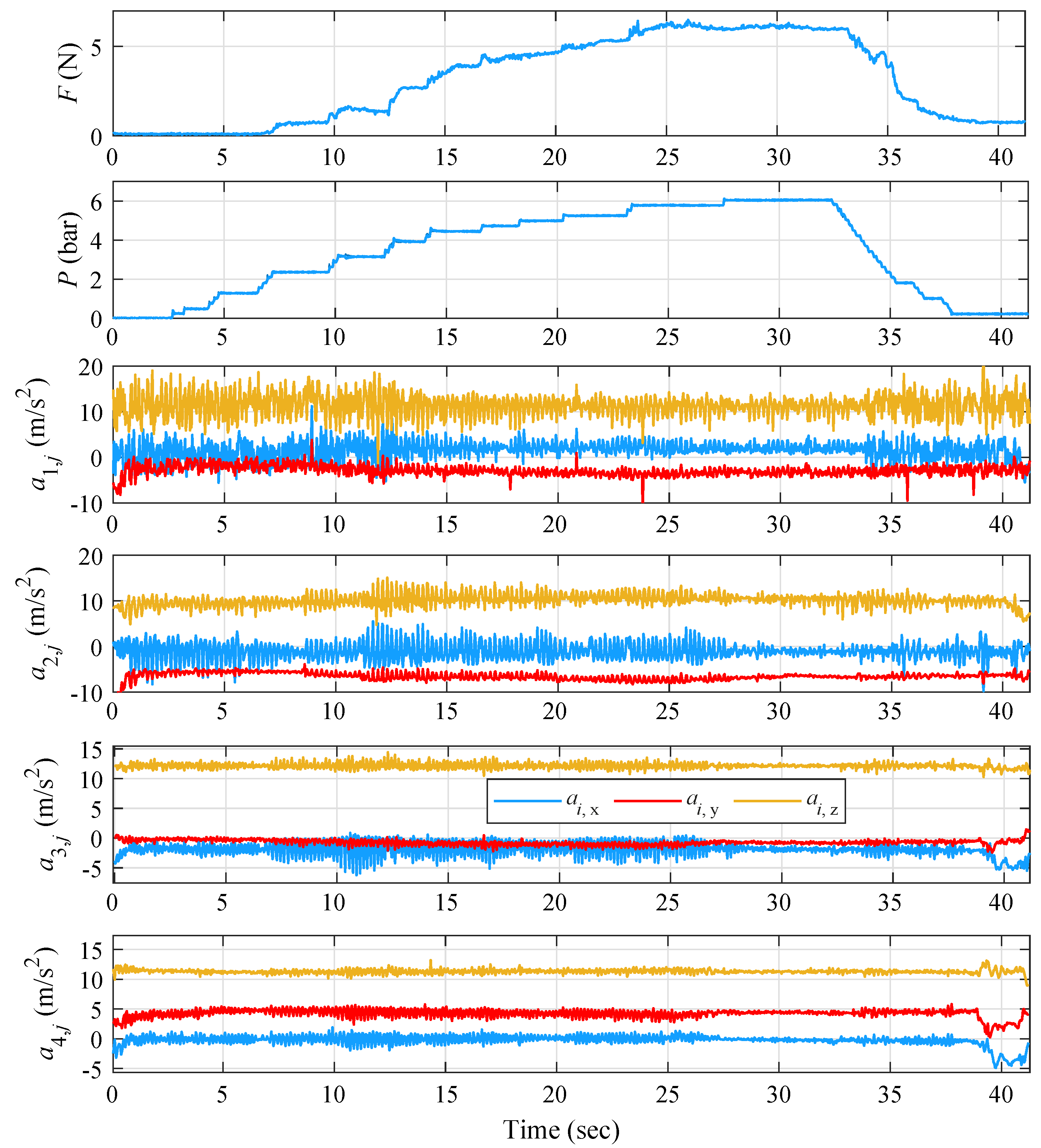
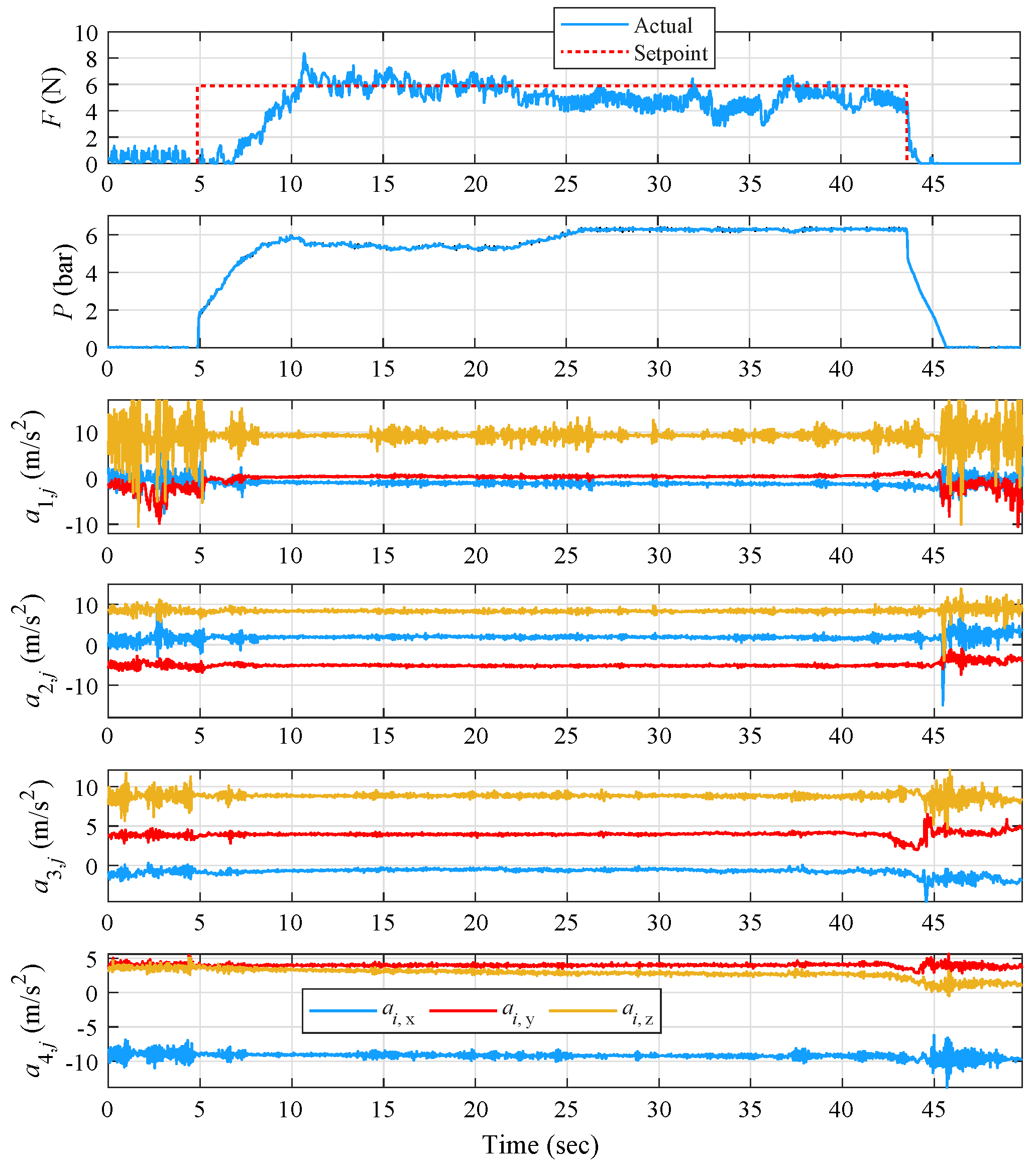
The open-loop evaluation of iteration (B) and the effect of applying resisting force on the metacarpal region was performed via an experiment examining the ET suppression for variable increases in pressure while the volunteer’s hand was in a straight position. The results, as defined in the previous subsections, are presented in
Figure 15.
Initially and before the increase in pressure, a similar tremor pattern is observed mainly on the index finger, reaching high-amplitude ET close to 5 Hz, while the amplitude is lower on the thumb and even lower on forearm points but under the same approximate frequency. Similar to the first (A)-(OL) experiment, the pressure follows an increasing and decreasing manner, reaching a maximum of approx. 6 bar, while the force alternates between 0–6 N. During the time period where the force is slowly increased (5–22 s), an increase in ET amplitude and frequency is observed at all four monitored parts of the hand. Interestingly, for the interval 11–14 s and during the stepwise increase in pressure, a sudden increase in ET is more evident. Then, closing with force stabilization, the ET amplitude and frequency gradually decrease, reaching a minimum during 27–33 s, when they gradually increase again on all four points with the sudden drop in pressure.
As shown in
Table 8 for the (B)-(OL) case, the application of resistive force on the metacarpal region still manages to effectively reduce ET frequency, but on lower maximum percentages than the ones achieved via (A). Specifically, the maximum reduction rates are encountered on the upper forearm, with 50% frequency. Reductions occur on all four measurement points, although frequency reduction on the index and thumb stays under 30%. The largest tremor frequency reduction is observed on the z axis of accelerometer placed on the upper forearm and amounts to 70%.
By observing
Table 9, and unlike the ET frequency, ET amplitude is mainly suppressed on the fingers by 56% and 53%, while for the lower part of the forearm, the reduction rate drops to 8%. The upper forearm tremor amplitude is reduced almost proportionally to its frequency at a rate of 44%. Although there are reduction percentages near 70% on all four measured hand parts,
is reduced significantly by 92%.
5.4. Prototype (B) Closed-Loop Evaluation
Similar to the (A)-(CL) case, the closed-loop evaluation of iteration (B) was initiated with a set-point reference force value set at approximately 6 N, as obtained from (B)-(OL) as a suitable force level for effective ET reduction, while the volunteer’s hand was in the relaxed state. The gain scheduler’s control parameters were defined in the same manner as described in
Section 5.2. The aforementioned parameters are presented in
Table 10.
From the results presented in
Figure 16, the initially high ET significantly decreased for all measurement points once the force approached the reference signal. The same behavior continues until the controller’s deactivation at
s, for all points except the index finger, where a small increase in ET amplitude is observed at 15 s, when the volunteer performed an involuntary finger movement, Finally, ET properties rise again to the same levels when disabling the controller.
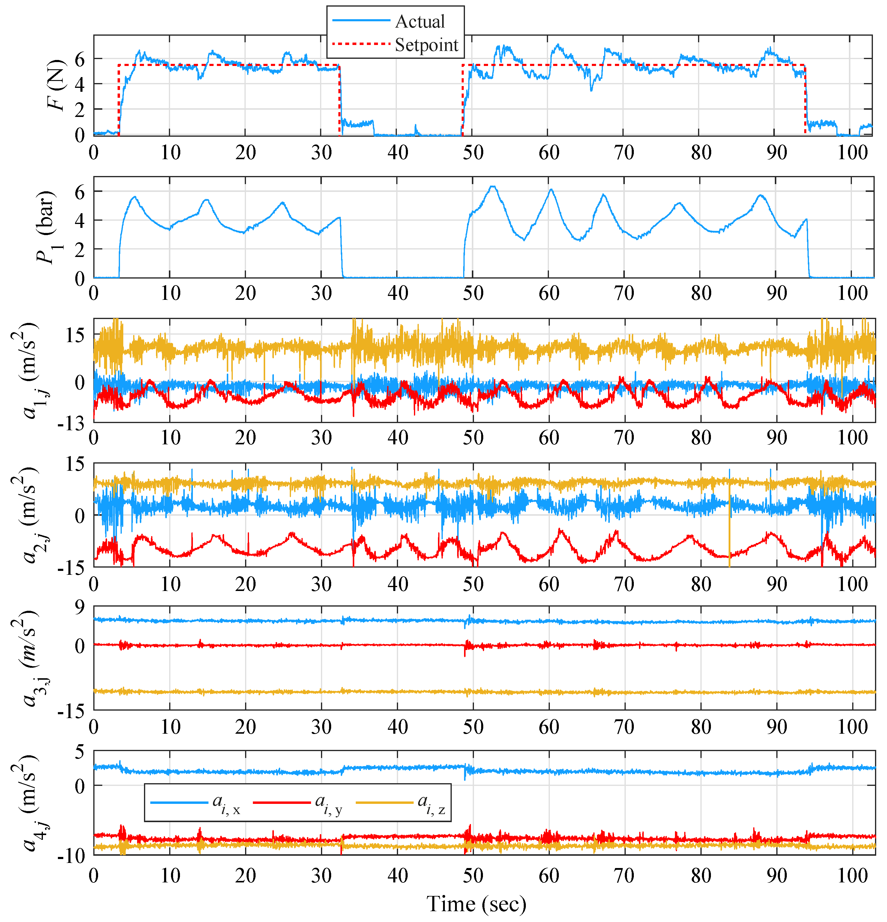
An additional experiment was performed while in closed-loop operation, where the controller was again activated in the presence of ET and the volunteer was asked to bend his fingers until they touched a spherical object and then to return them to their original position. This scenario was repeated two times. For the total duration of the experiment and throughout the volunteer’s motion, the control was fine-tuned to provide smooth and fast behavior with the absence of abrupt alterations in pressure. From the results presented in
Figure 17, it is clearly observed that during both controller activation periods 6–29 s and 40–66 s, ET amplitude decreases at all measurement points. The change of ET in the upper forearm approximates the corresponding diagrams of the lower forearm, although its frequency shows a larger decreasing tendency than that of the lower forearm. Interestingly, and in contrast to
Figure 13 observations, the forearm’s ET does not occur during the two control operations from 30 to 40 s.
By observing
Table 11, the largest mean decrease of tremor on the index finger appears on y axis with 46%. The highest decrease on the x and y axes appear in experiment 2 with percentages of 38% and 51%, respectively, while on the z axis, it is in experiment 1 with 48%. Both the experiments managed to reduce index ET frequency by 41%. Significant frequency tremor suppression is achieved on the thumb by 64% on the y and z axes, and with a 58% reduction in experiment 1. On the lower forearm, the maximum reduction is found on the z axis and at a rate of 75%, while the reduction rates on the x and y axes are at 35% and 53%, respectively. The largest decrease is observed in experiment 1 and on the z axis with 77%. Experiment 1 has the optimum rate of reduction of the frequency of tremor with 67%. On the upper forearm, as on the lower, the maximum reduction is detected on the z axis with 67%. The highest reduction on the x and axes is observed in experiment 1 with 78 and 70%, while on z axis, it is in experiment 2 at 76%. Experiment 1 proves to be the most effective in the case of ET frequency suppression with 69%.
According to
Table 12, the largest decrease in tremor amplitude noticed on the index is observed on average on the x axis with 79%. However, The largest decrease is observed on the y axis and in experiment 1 with 91%. In experiment 1, tremor amplitude is reduced optimally with 73%. As for the thumb, the largest reduction in tremor amplitude is observed on the x axis with 55%, significantly higher than the other two axes. The largest decrease on the x axis is found in experiment 2 at 75%. The ET amplitude is reduced by almost half during the first experiment. The maximum decrease on the lower forearm appears on the x axis with 48%. The largest tremor amplitude decrease on the x axis is observed in experiment 1 with 50%, while both experiments managed to reduce tremor amplitude by almost 30%. On the upper forearm, the maximum reduction is again detected on the x axis at 36%, while the reduction rates on the z axis remains close with 35%. The largest decrease is observed in experiment 2 on the x axis with 59%. Experiment 2 appears to have the highest reduction rate at 38%.
6. Conclusions
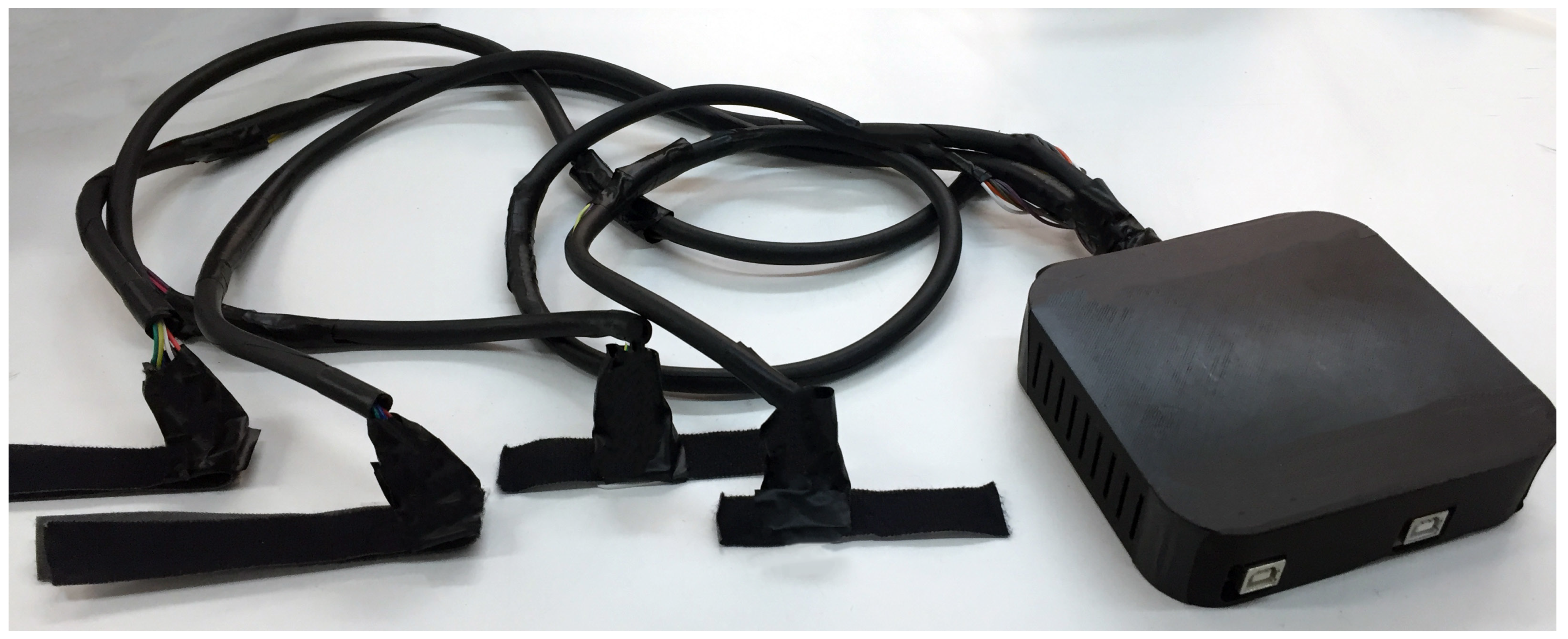
In this article, a soft exoskeletal glove for investigating Essential Tremor (ET) suppression was proposed. The glove setup concept followed a patch-and-use logic by avoiding the use of complex mechanisms comprising hard and heavy materials, while increasing the ease of installation and use without lowering the durability factor. For actuation, Pneumatic Artificial Muscles (PAMs) were utilized for their important advantages such as inherent compliance and high power-to-mass ratio. To investigate the glove’s potential in reducing ET via application of resisting forces on different parts of a user’s lower arm, two design iterations were implemented to apply localized force to the (A) index finger and (B) metacarpal region, while measuring the acceleration of four points including the distal phalanges of the index and thumb along with metacarpal and forearm regions. To this goal, a data acquisition setup was implemented and utilized for acquiring acceleration measurements in order to determine the effectiveness of the suppression iterations.
Both iterations were extensively evaluated under various motion scenarios by a chronic ET-diagnosed volunteer. The performed experimental sequences involved the prototypes’ evaluation initially under open-loop control of the kinesthetic force, and subsequently under closed loop sequences incorporating a PID control scheme. Specifically, regarding the tremor suppression attempts, iteration (A) showed a visible decrease in ET frequency and amplitude in the cases where the force reached a specific plateau, reaching a maximal decrease in metacarpal ET frequency and index finger ET amplitude of 70% and 75%, respectively. Using these plateau values as reference forces, closed-loop sequences incorporating a PID control scheme were performed, which further proved the setup methodology’s efficiency in suppressing ET, even in cases where the reference force was a constant setpoint and when the volunteer was performing voluntary movements with object-touching actions. Reductions in ET were recorded in all investigated cases, which reached a maximal reduction rate of 75 and 70% for the index ET amplitude and forearm ET frequency, respectively. Similarly, and in accordance with the open-loop case, the index finger appeared to have the largest tremor amplitude reduction, thus proving the effect of the experimental strategy. At the same time, the maximum ET frequency reduction was observed in the forearm region, a part of the hand where, for iteration (A), the force is not directly exercised on.
Regarding the open-loop evaluation of iteration (B) and the application of force directly on the metacarpal area, the experiment conducted resulted in approximately 50% reduction in ET amplitude for all four measured parts of the hand. Furthermore, the device was capable of halving the metacarpal’s and forearm’s tremor frequency, while lower reduction rates were achieved for the two fingers. During the closed-loop evaluation for iteration (B), ET frequency reduction rates followed a similar pattern to the open-loop case scenario. The ET frequency of metacarpal and forearm areas was reduced by almost 70%. In parallel, the index and thumb fingers’ frequencies were also decreased but with the reduction rates not exceeding 58%. Finally, ET amplitude was reduced by 73% on the index finger and by 50% on the thumb, while the respective percentages for the metacarpal and forearm regions stayed below 40%.
The investigation showed that both PAM-enabled approaches, regarding kinesthetic force exertion on the metacarpal and index finger, were able to effectively reduce ET via constant setpoint forces, with the metacarpal solution providing slightly less reductions during closed-loop control but with the important advantage of not constricting finger movements.
Moreover, during the experimental trials and results, an interesting finding was made with the increase in ET amplitude in the metacarpal and forearm areas simultaneously with the tremor reduction in the fingers. This ”tremor translation“ phenomenon was observed only for iteration (A), which seeks to repress the tremor by exerting force directly to the fingers, and not for iteration (B), where the force directly affects the metacarpal region.
All presented findings highlight the exoskeletal glove’s potential for future investigations involving different tremor types. Further experimentation on male/female volunteers of different ages, clinical trials on volunteers suffering from various tremor-causing neurological disorders (e.g., Parkinson’s), validation of safety during alternative and more intense active motion strategies, as well as implementation of more advanced model-based algorithms for active force and compliance control are considered a necessity for further and future evaluation of the proposed approach.


