Abstract
Vibration response and amplitude frequency characteristics of a controlled nonlinear meso-scale beam under periodic loading are studied. A method including a general analytical expression for harmonic balance solution to periodic vibration and an updated cycle iteration algorithm for amplitude frequency relation of periodic response is developed. A vibration equation with the general expression of nonlinear terms for periodic response is derived and a general analytical expression for harmonic balance solution is obtained. An updated cycle iteration procedure is proposed to obtain amplitude frequency relation. Periodic vibration response with various frequencies can be calculated uniformly using the method. The method can take into account the effect of higher harmonic components on vibration response, and it is applicable to various periodic vibration analyses including principal resonance, super-harmonic resonance, and multiple stationary responses. Numerical results demonstrate that the developed method has good convergence and accuracy. The response amplitude should be determined by the periodic solution with multiple harmonic terms instead of only the first harmonic term. The damping effect on response illustrates that vibration responses of the nonlinear meso beam can be reduced by feedback control with certain damping gain. The amplitude frequency characteristics including anti-resonance and resonant response variation have potential application to the vibration control design of nonlinear meso-scale structure systems.
1. Introduction
The meso-scale beam is an important component of many precise instruments such as micro-sensors or micro-actuators [1]. The large amplitude motion of the beam subjected to strong loading, e.g., a cantilever beam under strong support motion loading, leads to complicated nonlinear vibration [2], which will degrade the mechanical performance of the instruments. Thus, vibration control of the beam is highly desirable, and in this connection, the vibration response and amplitude frequency characteristics of the controlled nonlinear beam need to be studied. Some investigations on the nonlinear dynamics of meso beams have been reported, but there is a paucity of research on its vibration control.
For a meso-scale beam, a conventional mechanical model such as that based on Bernoulli–Euler theory can be applied. However, the foundational frequency of the beam is high due to its small length and in general, it is larger than the loading frequency. Thus, first several vibration modes will be involved in the vibration response, albeit the first mode vibration is dominant. Increasing structural damping is a common strategy, in particular, for resonant response mitigation [3,4]. However, damping produced by passive control is limited, and active feedback control is necessary to execute large artificial damping. The controlled beam can be converted into a multi-degree-of-freedom (MDOF) nonlinear system. Feedback control of MDOF systems has been studied [5,6,7,8,9,10,11,12,13,14]. However, the control effectiveness of a large damping gain on vibration mitigation of the nonlinear meso beam needs to be studied further.
Most of the investigations on nonlinear dynamics of the meso beam are based on experiments, while theoretical studies on the nonlinear vibration and control are limited. Periodic loading is a class of important real excitations, and periodic vibration and amplitude frequency relation can represent dynamic characteristics of the beam system with various frequencies. The harmonic balance method is suitable for periodic vibration analysis of the nonlinear beam system to obtain amplitude frequency relation by uniform procedure in a wide frequency band [2,15,16,17,18,19,20]. It converts a nonlinear system equation into a set of algebraic equations for harmonic coefficients of periodic response, and the response based on basic harmonic components can be improved by using high harmonic components. However, general forms of harmonic balance equations, general analytical expressions of periodic response solutions, and an effective iteration procedure for amplitude frequency relation need to be developed further for the controlled nonlinear meso beam.
In the present paper, the vibration response and amplitude frequency characteristics of a controlled nonlinear meso-scale beam under periodic loading are studied. A method including a general analytical expression for harmonic balance solution to periodic vibration and an updated cycle iteration algorithm for amplitude frequency relation of periodic response is developed for the nonlinear beam system. In Section 2, a vibration equation for the controlled beam is established, and a general expression of nonlinear terms for periodic response with multiple harmonic terms is derived. A general analytical expression for a harmonic balance solution to periodic vibration is obtained. In Section 3, an updated cycle iteration procedure for amplitude frequency relation and periodic response solution is proposed. Then, a periodic vibration response with various frequencies is calculated uniformly using the method by only changing the frequency. An accurate response can be obtained by using adequate high harmonic components. In Section 4, numerical results on the periodic vibration response of the controlled nonlinear beam system are given to demonstrate the good convergence and accuracy of the developed method. The amplitude frequency characteristics including principal, super, and fractional harmonic resonances are perceived. The effect of damping feedback gain on vibration response reduction of the controlled nonlinear beam system is explored.
2. General Analytical Solution to Controlled Nonlinear Beam
The meso-scale beam is an important component of many precise instruments such as micro-sensors or micro-actuators. A conventional mechanical model such as that based on Bernoulli–Euler theory is suitable to the meso beam. The large amplitude motion of the beam subjected to such as strong support loading leads to complicated nonlinear vibration, which will degrade the performance of the instruments. The beam vibration needs to be controlled, and vibration characteristics of the controlled beam need to be identified. A meso beam with control under transverse excitation, as shown in Figure 1, is addressed first in this study. Its nonlinear vibration equation in dimensionless form can be expressed as [21].
where w is the non-dimensional transverse displacement, α1 is the mass coefficient, α2 is the damping coefficient, α3 is the linear stiffness coefficient, α4 is the nonlinear stiffness coefficient, fe is the non-dimensional transverse loading, uc is the feedback control, y∈[0,1] is the non-dimensional longitudinal coordinate, and t is the time variable. Equation (1) is a partial differential equation and can be converted into a set of ordinary differential equations by using the Galerkin method. Vibration modes of the beam are determined based on boundary constraint conditions, and the displacement w is expanded into series using the modes. The displacement expansion is
where Nw is the number of modes, φi is the ith mode, and qi is the ith modal displacement. The mode vector Φ and modal displacement vector Q are, respectively
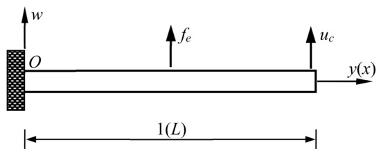
Figure 1.
Meso-scale beam with control uc under loading fe.
For instance, a cantilever beam has its vibration modes
where the parameter βi is determined by the algebraic equation
The first three solutions to Equation (5) are 1.875, 4.694, and 7.855. The ratio of the second or third natural frequency to the first natural frequency of the cantilever beam is larger than that of the corresponding simply supported beam.
Substituting expression (2) into Equation (1), pre-multiplying the equation by ΦT and integrating it with respect to y yields ordinary differential equations in the matrix form
where M is the modal mass matrix, C0 is the modal damping matrix, K0 is the modal linear stiffness matrix, G0 is the modal nonlinear restoring force vector, F is the modal loading vector, and U is the modal control vector. Their expressions are
In general, M, C0, and K0 are diagonal matrices. G0 is a nonlinear function vector of modal displacement Q. The feedback control uc is a function of displacement w and velocity, and thus, the modal control U is a function of the modal displacement Q and modal velocity. Nonlinear control for the nonlinear system can be expressed as
where Cc is the linear damping feedback gain matrix, Kc is the linear stiffness feedback gain matrix, and Gc is the nonlinear feedback control vector. By incorporating the control (8) into the uncontrolled system, Equation (6) is rewritten as
where C = C0 + Cc, K = K0 + Kc, and G = G0 + Gc. The damping and stiffness of system (9) can be adjusted by feedback control, and thus, the system vibration or beam vibration can be controlled.
Equation (9) is a nonlinear ordinary differential matrix equation for the controlled beam in multiple degrees-of-freedom coupling vibration. The lth element of the nonlinear term can be expanded into the power series
where Nj is an integer and kNl,i1i2…ij is the nonlinear stiffness coefficient. For the beam with cubic nonlinearity (1) and corresponding control, the lth element of the nonlinear term becomes
where kNl,ijk is the cubic nonlinear stiffness coefficient. The nonlinear restoring force vector is expressed as
where KN is a four-dimensional tensor of nonlinear stiffness coefficients and ⊗ denotes a generalized product of tensor and vector.
Periodic vibration and amplitude frequency relation represent the frequency response characteristics of the controlled beam system with various frequencies, which are important for dynamic optimization design. The harmonic balance method is suitable for nonlinear periodic vibration analysis to obtain amplitude frequency relation by a uniform procedure in a wide frequency band [2]. A general analytical expression and effective iteration solution procedure for system (9) will be developed for the first time in the following. The periodic loading is expressed as
where ω is the loading frequency, Fsk and Fck are the harmonic coefficient vectors of the loading, and Nf is an integer. The harmonic vectors Φs and Φc with coefficient matrices Fs and Fc are, respectively
The integer Nq is larger than Nf, and thus, later columns of the matrices Fs and Fc are zeros. The periodic response of the vibration system to the periodic loading is expanded as
where Ak and Bk are harmonic coefficient vectors of the response. The coefficient matrices AQ and BQ are, respectively
As a result of the high-order harmonic effect, the term number Nq in the expansion for response is larger than Nf for loading. The lth element of the response vector Q is
where alk and blk are harmonic coefficients of the response. The response coefficient vectors Ak and Bk have the expressions
By substituting expression (15) into nonlinear term (12), using harmonic function properties and neglecting the higher harmonic part, the nonlinear term can be obtained as
where KN3s and KN3c are the function matrices of the response coefficients AQ and BQ. The lth element of the vector G is
where kN3s,lm and kN3c,lm are the harmonic coefficients of the nonlinear term. The coefficients can be further expressed as
where dm and em are functions of the response coefficients alk and blk. They are
with
where μ1, μ2, and μ3 are +1 or −1, Sμ and Cμ denote all combinations of (μ1l1, μ2l2, μ3l3), j1 is for λj1 = 1 and j2 is for λj2 = 2, and δ is the Kronecker delta function. Expressions (22) and (23) indicate that dm and em are cubic power functions of the response coefficients alk and blk. As such, general expression of the nonlinear term has been obtained in Equations (19)–(24) for the periodic response with multiple harmonic terms, which is given first for the meso beam.
According to the harmonic balance method, substituting response (15) with expression (19) and loading (13) into Equation (9) and balancing each harmonic term yields algebraic equations for response coefficients AQ and BQ as
where the vibration frequency matrix is
Equations (25) and (26) are algebraic matrix equations, and they can be rearranged as equations for the response coefficient vector of alk and blk to solve. However, equations for the mth column Am of the matrix AQ and the mth column Bm of the matrix BQ are obtained from Equations (25) and (26) as
where KN3s,⋅m is the mth column vector of the matrix KN3s while KN3c,⋅m is the mth column vector of the matrix KN3c. By solving Equations (28) and (29), response coefficient vectors Am and Bm with elements alm and blm are obtained as
where
Equation (30) provides a set of general harmonic balance solution formulae for periodic vibration of the nonlinear system (9) representative of the controlled meso beam. By the equation, the harmonic response coefficients Am and Bm and then AQ and BQ can be obtained, and thus, the periodic vibration response of the system is determined by Equation (15) and the beam displacement is calculated by Equation (2). The vibrational amplitude frequency characteristics of the controlled beam are obtained by means of the responses under various frequencies. The accuracy of the responses can be improved by increasing numbers of expansion terms in Equations (2) and (15). Convergence of the response expansion is determined by relative differences of the harmonic response coefficients, i.e., and . However, because KN3s,⋅m and KN3c,⋅m depend on response coefficients Am and Bm, Equation (30) is nonlinear and will be solved by iteration.
3. Iteration Procedure for Vibration Response
Equations (28) and (29) or (30) include 2 × Nw × Nq algebraic equations for harmonic response coefficients alm and blm (l = 1, 2, …, Nw; m = 1, 2, …, Nq). The equations can be rewritten generally as
where fa,lm and fb,lm are functions of AQ and BQ. AQ and BQ are matrices by assembling alm and blm, respectively, as expressions (16) and (18). Based on Equations (32) and (33), iterative equations are given according to the generalized Newton iteration algorithm as
where superscript “k” denotes the kth step of iteration, functions f and θ are
Derivatives of the function f are given by
where the parameter β is set as a small value, e.g., 10−5. Equation (34) presents a general iteration algorithm for the harmonic balance solution to periodic vibration of the nonlinear system (9). However, a computational expense of the iterative Equation (34) is large due to coupling high dimensions.
To improve computational efficiency, based on the partially uncoupled Equation (30), another form of the iterative equation is obtained as
where Am and Bm are vectors respectively by assembling alm and blm, is a part of KN3s,⋅m independent of Am and the other part depends on Am, is a part of KN3c,⋅m independent of Bm and the other part depends on Bm, and the matrix
The iteration solution procedure for solving Equation (37) or (34) is proposed as follows: first, select initial values of the response coefficient matrices AQ and BQ, e.g., as a solution to the linearized system; second, substituting the initial values into Equation (37) or (34) yields the next step values of the response coefficient vectors Am and Bm, and Am and Bm are used to update the last step values and to calculate the response coefficient vectors Am+1 and Bm+1 (m = 1, 2, …, Nq−1), that is constantly updated cycle; third, examine the convergence of the response coefficient matrices AQ and BQ by using relative differences of adjacent step values of the response coefficients, i.e.,
where γI is a small value representing iteration accuracy and k = 1, 2, … If the current step values of the response coefficients do not satisfy condition (39), continue to carry out the next step until convergence. This iteration procedure is called updated cycle iteration. Finally, the harmonic response coefficients AQ and BQ are obtained and used to calculate periodic responses (15) and (2), by which the amplitude frequency characteristics of the vibration response of the controlled beam system can be determined. The vibration response with various frequencies can be calculated using the uniform method by only changing frequency. Accurate response will be obtained by using adequate high harmonic components.
The above method, including a general analytical expression for a harmonic balance solution to periodic vibration and an updated cycle iteration algorithm for amplitude frequency relation of periodic response, is a uniform method for a nonlinear system of the controlled mseo-scale beam under various frequencies, and it is suitable for obtaining amplitude frequency relation in a wide frequency band. It is also applicable to various periodic vibration analyses including principal resonant response, super-harmonic resonant response, and multiple stationary responses. The dynamic stability of the periodic vibration can be solved by using the direct eigenvalue analysis approach for systems with periodically varying parameters [20,21].
When loading frequency ω keeps away from the resonant frequencies of the nonlinear system, a non-resonant response as a function of frequency ω can be obtained by using the above method. When the loading frequency ω is close to a resonant frequency of the nonlinear system, a principal resonant response as function of frequency ω can be obtained by using the uniform method. In the case of multiple response solutions, a resonant response obtained depends on initial iteration values and vibration stability. When the loading frequency ω is close to 1/n-times resonant frequency of the nonlinear system (n is an integer larger than 1), a super-harmonic resonance near nω can occur, and in the meantime, a response component with frequency ω also exists. In this case, the vibration response obtained has the frequency of ω.
The vibration response of the nonlinear system (9) or beam (1) is composed of multiple harmonic components, and its amplitude will be obtained by periodic solution under maximum condition. For example, the displacement response amplitude on y0 is determined by periodic solution varying with time in a period under the condition . As a consequence, the amplitude frequency characteristics of periodic vibration can be determined.
4. Numerical Results and Discussion
To illustrate the application of the developed method and amplitude frequency characteristics, consider a meso-scale cantilever beam with control under a periodic loading. Its nonlinear vibration equation in dimensionless form is as Equations (1) and (9), in which αi (i = 1, 2, 3, 4) are constants for the uniform beam. The foundational frequency of the meso beam is high and generally larger than the loading frequency. Thus, first several vibration modes will be involved in vibration response, while the first mode vibration is dominant. Increasing structural damping is a common strategy for resonant response suppression. Damping produced by passive control is limited, whereas active feedback control can produce large artificial damping, which is incorporated in damping coefficient of system (9). The effect of the damping on vibration response characteristics will be explored for control at the midpoint. The periodic support loading is F = Fs1 sinωt in system (9). After normalized with respect to mass, non-dimensional damping coefficient, linear stiffness coefficient, nonlinear stiffness coefficient, and loading amplitude for the first mode are denoted by c, k1, k3, and Fs1, respectively. The other coefficients can be determined by these coefficients based on Equations (4), (7), and (8). Using the developed method, harmonic response coefficients (18) and periodic vibration response (2) of the beam system are obtained, which are used to determine amplitude frequency characteristics. In calculation, basic parameter values are k1 = 1.0, c = 0.1, k3 = 0.12, Fs1 = 0.2, and y0 = 1 unless otherwise specified. Numerical results on the non-dimensional vibration response and amplitude frequency relation are shown in Figure 2, Figure 3, Figure 4, Figure 5, Figure 6, Figure 7, Figure 8, Figure 9, Figure 10, Figure 11, Figure 12, Figure 13 and Figure 14, which have been verified through direct numerical simulation.
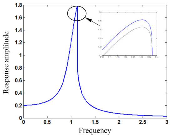
Figure 2.
Amplitude (wAm) frequency (ω) relation around principal resonance for loading amplitude Fs1 = 0.2 (blue solid line: response based on periodic solution; black dotted line: response based on first harmonic term).
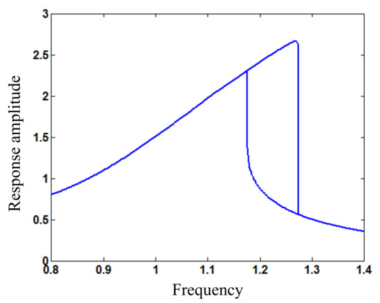
Figure 3.
Amplitude (wAm) frequency (ω) relation around principal resonance for loading amplitude Fs1 = 0.34.
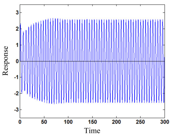
Figure 4.
Larger amplitude response (w) varying with time (t) for loading frequency ω = 1.24 by numerical simulation from initial displacement 1.0 and velocity 2.5.
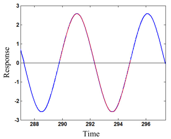
Figure 5.
Stationary larger-amplitude response (w) varying with time (t) for loading frequency ω = 1.24 (blue solid line: numerical simulation; red dotted line: the developed method).
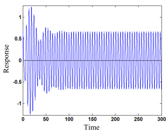
Figure 6.
Smaller amplitude response (w) varying with time (t) for loading frequency ω = 1.24 by numerical simulation from initial displacement 1.0 and velocity 0.
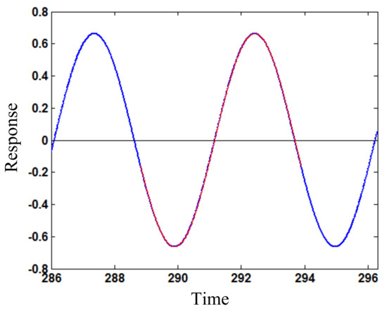
Figure 7.
Stationary smaller-amplitude response (w) varying with time (t) for loading frequency ω = 1.24 (blue solid line: numerical simulation; red dotted line: the developed method).
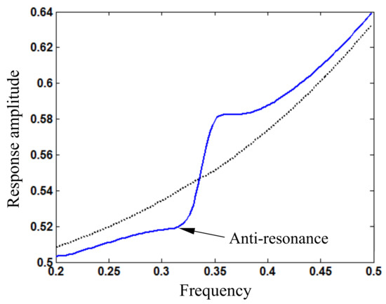
Figure 8.
Amplitude (wAm) frequency (ω) relation around super-harmonic resonance for loading amplitude Fs1 = 0.5 (blue solid line: response based on periodic solution; black dotted line: response based on first harmonic term).

Figure 9.
Stationary response (w) varying with time (t) for loading frequency ω = 0.35 (blue solid line: response based on periodic solution; black dotted line: response based on first harmonic term).
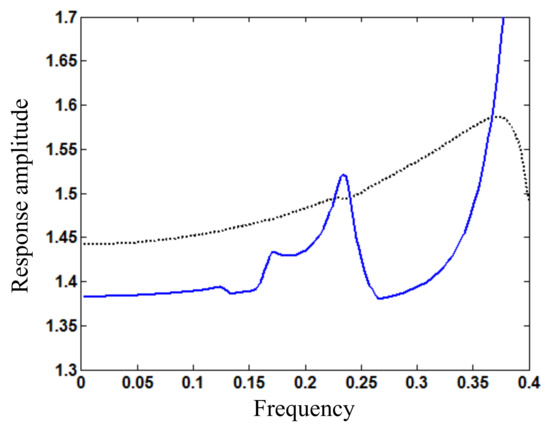
Figure 10.
Amplitude (wAm) frequency (ω) relation around fractional harmonic resonance for loading amplitude Fs1 = 1.7 (blue solid line: response based on periodic solution; black dotted line: response based on first harmonic term).
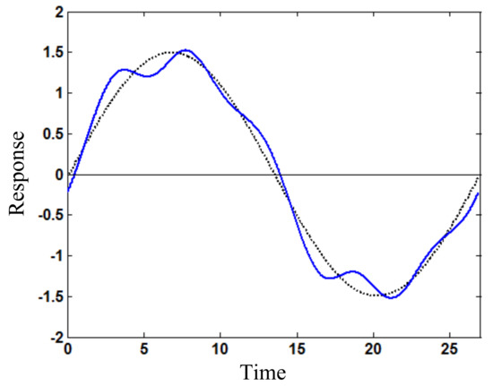
Figure 11.
Stationary response (w) varying with time (t) for loading frequency ω = 0.23 (blue solid line: response based on periodic solution; black dotted line: response based on first harmonic term).
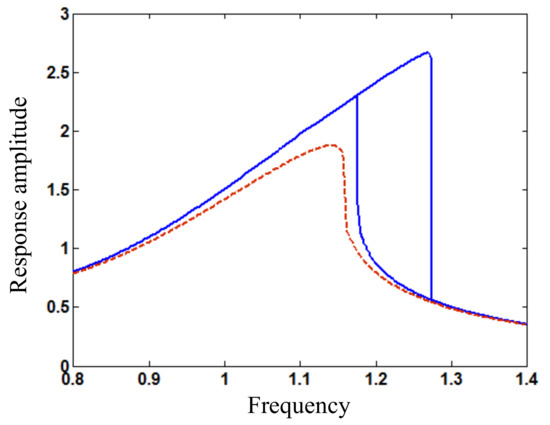
Figure 12.
Amplitude (wAm) frequency (ω) relation around principal resonance for loading amplitude Fs1 = 0.34 and different damping coefficients c (blue solid line: c = 0.1; red dashed line: c = 0.16).
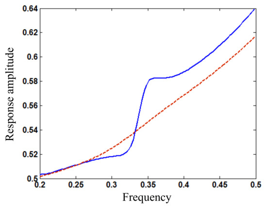
Figure 13.
Amplitude (wAm) frequency (ω) relation around super-harmonic resonance for loading amplitude Fs1 = 0.5 and different damping coefficients c (blue solid line: c = 0.1; red dashed line: c = 0.45).
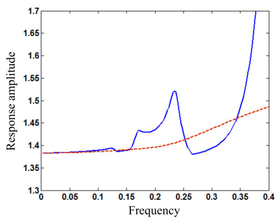
Figure 14.
Amplitude (wAm) frequency (ω) relation around fractional harmonic resonance for loading amplitude Fs1 = 1.7 and different damping coefficients c (blue solid line: c = 0.1; red dashed line: c = 1.25).
Figure 2 shows the amplitude frequency relation around principal resonance for periodic vibration response of the beam under Fs1 = 0.2. The amplitude frequency relation around principal resonance based on the first expansion term of the response is also given for comparison. The non-dimensional resonant frequency is close to 1.13, and the non-dimensional resonant response amplitude is 1.78 determined by the developed periodic solution, which is larger than 1.76 based on only the first expansion term. The difference will be shown further in the subsequent results, which increases with loading amplitude. Thus, the response amplitude should be determined by periodic solution (2) with (15) instead of only the first harmonic term. If the resonant response amplitude is larger than 1, the nonlinear term of the system cannot be regarded as small in resonance.
As the loading amplitude increases to Fs1 = 0.34, Figure 3 shows the amplitude frequency relation around principal resonance for periodic vibration response of the beam. It is seen that two stationary responses exist in a frequency interval [1.17, 1.27], which can be caused also by increasing the nonlinear stiffness coefficient. If the loading amplitude or nonlinear stiffness increases, the multiple responses region will be enlarged in amplitude and frequency and move right. In particular, the initial state region, which tends to smaller amplitude response with time, is larger than that for the larger amplitude response. Thus, the smaller amplitude response has a larger stability probability than the larger amplitude response; that is, the smaller amplitude response is more likely to occur practically. Figure 4 shows the larger amplitude response varying with time for the loading frequency ω = 1.24 by numerical simulation from initial displacement 1.0 and velocity 2.5. The stationary response amplitude is 2.58. Figure 5 illustrates that the stationary response by numerical simulation accords completely with that by using the developed method. Figure 6 shows the smaller amplitude response (stationary amplitude 0.66) varying with time for the loading frequency ω = 1.24 by numerical simulation from initial displacement 1.0 and velocity 0. Figure 7 illustrates again that the stationary response by numerical simulation agrees completely with that by using the developed method.
As the loading amplitude increases to Fs1 = 0.5, Figure 8 shows the amplitude frequency relation around super-harmonic resonance for the periodic vibration response of the beam. It is seen that the amplitude frequency curve of the response based on only the first harmonic term does not display any peak and valley, but the curve of the response determined by multiple harmonic terms of periodic solution (15) has a peak and a valley. In particular, the response valley or anti-resonant response near frequency ω = 0.32 in the nonlinear system is obtained for the first time. For frequency ω > 0.34, the response amplitude determined by the periodic solution is larger than that based on only the first harmonic term, and for frequency ω < 0.33, the response amplitude determined by the periodic solution is smaller than that based on only the first harmonic term. Thus, it is supported further that the response amplitude should be determined by periodic solution (2) with (15) instead of only the first harmonic term. The dynamic characteristics including anti-resonance have potential application to vibration control design of meso-scale nonlinear systems. Figure 9 illustrates that the stationary response varying with time in amplitude and shape determined by the periodic solution is different from that based on only the first harmonic term, where the loading frequency ω = 0.35. The response amplitude is 0.58 for the former and 0.55 for the latter. The relative difference is 5%, but the variation of dynamic characteristics is remarkable, as shown in Figure 8. The response contains a super-harmonic resonance component with frequency 3ω and basic harmonic component with frequency ω, which is relatively large. The response peak increases with the loading amplitude.
As the loading amplitude increases to Fs1 = 1.7, Figure 10 shows the amplitude frequency relation around fractional harmonic resonance (e.g., 9ω/2) for the periodic vibration response of the beam. Figure 11 illustrates that the stationary response varying with time particularly in shape determined by the periodic solution is largely different from that based on only the first harmonic term. The loading frequency is ω = 0.23, and the stationary response amplitude is 1.52. The relative difference of amplitudes based on the periodic solution and first harmonic term for frequency ω = 0.4 is 30.4%. The response peak also increases with the loading amplitude.
For the controlled nonlinear beam system under the harmonic loading with amplitude Fs1 = 0.34, when the damping coefficient increases to exceed 0.16, the two stationary responses around principal resonance in Figure 3 disappear and become a new pattern of response, as shown in Figure 12. Thus, the principal resonant responses can be controlled by increasing the damping gain. For the controlled beam system under the harmonic loading with amplitude Fs1 = 0.5, when the damping coefficient increases to exceed 0.45, the peak response around super-harmonic resonance and the anti-resonant response in Figure 8 disappear, as shown in Figure 13. Thus, large damping or feedback gain is required to mitigate the beam vibration with frequency smaller than the principal resonant frequency. However, for the controlled beam system under the harmonic loading with amplitude Fs1 = 1.7, the peak response around fractional harmonic resonance in Figure 10 disappears only when the damping coefficient increases up to 1.25, as shown in Figure 14. In fact, it is unpractical to produce such large damping in passive control, but the large damping or feedback gain can be generated by active control as artificial damping. Thus, the resonant responses of the nonlinear meso beam can be reduced by feedback control with certain damping gain.
For an actual meso beam, its basic geometrical and physical parameters are obtained first to determine the parameters of model (1) such as αi (i = 1,2,3,4), as shown in reference [21] and by Equations (4), (7), and (8). Then, the model parameters are updated by test results compared with analytical results on amplitude frequency relation. The updated model can be used for dynamic analysis and control design of the beam.
5. Conclusions
The method including a general analytical expression for harmonic balance solution to periodic vibration and an updated cycle iteration algorithm for amplitude frequency relation of periodic response has been developed for the controlled nonlinear meso-scale beam. The general expression of nonlinear terms in the nonlinear system for periodic response with multiple harmonic terms is derived. The general analytical expression for harmonic balance solution to periodic vibration of the nonlinear system is obtained. The updated cycle iteration procedure for amplitude frequency relation and periodic response solution is proposed. The developed method has the following main advantages: (1) it is a unified method for nonlinear systems with various frequencies, and periodic vibration responses for different frequencies can be calculated uniformly by only changing frequency; (2) it is suitable for obtaining the amplitude frequency relation of nonlinear systems in a wide frequency band and for effective numerical computation; (3) it can take into account the effect of higher harmonic components on vibration response; and (4) it is applicable to various periodic vibration analyses including principal resonant response, super-harmonic resonant response, and multiple stationary responses.
The amplitude frequency characteristics of the controlled nonlinear meso beam and the effect of damping feedback gain on vibration response have been studied. Numerical results on vibration response of the beam with various damping and loading amplitudes have demonstrated that: (1) the developed method has good convergence and accuracy with increasing response expansion terms, and the response amplitude should be determined by the periodic solution with multiple harmonic terms instead of only the first harmonic term; (2) the amplitude frequency characteristics around the principal resonance of the controlled beam system show two stationary responses for large loading amplitude and nonlinear stiffness coefficient, the resonant frequency is dependent on the loading and response amplitudes, the region of multiple responses can be enlarged in amplitude and frequency as the loading amplitude or nonlinear stiffness increases, and the smaller amplitude response has a larger stability probability than the larger amplitude response in terms of the initial states region of stable vibration; (3) the amplitude frequency curve of vibration response near super-harmonic resonance has a peak and a valley for a large loading amplitude, the response valley or anti-resonant response in the nonlinear system is obtained for the first time, and the dynamic characteristics have potential application to vibration control design of nonlinear meso structures; (4) the peak response with frequency around super-harmonic resonance or fractional harmonic resonance increases with loading amplitude; and (5) the principal resonant responses of the nonlinear beam system can be controlled by increasing damping gain, the response around super-harmonic resonance can be mitigated by feedback control with large damping gain, and the response around fractional harmonic resonance with frequency smaller than the principal resonant frequency cannot be mitigated effectively by passive control, but it can be controlled by active feedback with large artificial damping. Thus, the vibration responses of the nonlinear meso beam can be reduced by feedback control with certain damping gain. The vibrational amplitude frequency characteristics including anti-resonance and resonant response variation have potential application to vibration control or dynamic optimization design of nonlinear meso-scale structure systems.
However, the developed method is limited to periodic vibration analysis, and a method for non-periodic vibration analysis needs to be developed further. The analysis method is expected to apply to an actual meso-scale structure for dynamic optimization design and experimental verification.
Author Contributions
Conceptualization, Z.-G.Y. and Y.-Q.N.; methodology, Z.-G.Y. and Y.-Q.N.; software, Z.-G.Y.; validation, Z.-G.Y.; writing—original draft preparation, Z.-G.Y.; writing—review and editing, Y.-Q.N. and Z.-G.Y.; project administration, Z.-G.Y. and Y.-Q.N.; funding acquisition, Z.-G.Y. and Y.-Q.N. Both authors have read and agreed to the published version of the manuscript.
Funding
This research was funded by the National Natural Science Foundation of China (grant number 12072312), the Research Grants Council of the Hong Kong Special Administrative Region (grant number R-5020-18), and the Innovation and Technology Commission of the Hong Kong Special Administrative Region (grant number K-BBY1).
Institutional Review Board Statement
Not applicable.
Informed Consent Statement
Not applicable.
Data Availability Statement
Not applicable.
Conflicts of Interest
The authors declare no conflict of interest.
References
- Wang, X.F.; Wei, X.Y.; Pu, D.; Huan, R.H. Single-electron detection utilizing coupled nonlinear microresonators. Microsyst. Nanoeng. 2020, 6, 78. [Google Scholar] [CrossRef]
- Nayfeh, A.H.; Mook, D.T. Nonlinear Oscillations; John Wiley & Sons: New York, NY, USA, 1979. [Google Scholar]
- Soong, T.T.; Spencer, B.F. Supplemental energy dissipation: State-of-the-art and state-of-the-practice. Eng. Struct. 2002, 24, 243–259. [Google Scholar] [CrossRef]
- Casciati, F.; Rodellar, J.; Yildirim, U. Active and semi-active control of structures—Theory and applications: A review of recent advances. J. Intell. Mater. Syst. Struct. 2012, 23, 1181–1195. [Google Scholar] [CrossRef]
- Stengel, R.F. Optimal Control and Estimation; John Wiley & Sons: New York, NY, USA, 1994. [Google Scholar]
- Fleming, W.H.; Soner, H.M. Controlled Markov Processes and Viscosity Solutions; Springer: New York, NY, USA, 2006. [Google Scholar]
- Fisco, N.R.; Adeli, H. Smart structures: Part I—Active and semi-active control. Sci. Iran. A 2011, 18, 275–284. [Google Scholar] [CrossRef] [Green Version]
- Spencer, B.F.; Nagarajaiah, S. State of the art of structural control. ASCE J. Struct. Eng. 2003, 129, 845–856. [Google Scholar] [CrossRef]
- Ying, Z.G.; Ni, Y.Q.; Duan, Y.F. Parametric optimal bounded feedback control for smart parameter-controllable composite structures. J. Sound Vib. 2015, 339, 38–55. [Google Scholar] [CrossRef]
- Xu, Z.D.; Xu, F.H.; Chen, X. Vibration suppression on a platform by using vibration isolation and mitigation devices. Nonlinear Dyn. 2016, 83, 1341–1353. [Google Scholar] [CrossRef]
- Ying, Z.G.; Zhu, W.Q. Optimal bounded control for nonlinear stochastic smart structure systems based on extended Kalman filter. Nonlinear Dyn. 2017, 90, 105–114. [Google Scholar] [CrossRef]
- Wang, Q.; Li, H.N.; Zhang, P. Vibration control of a high-rise slender structure with a spring pendulum pounding tuned mass damper. Actuators 2021, 10, 44. [Google Scholar] [CrossRef]
- Xu, Z.D.; Dong, Y.R.; Chen, S.; Guo, Y.Q.; Li, Q.Q.; Xu, Y.S. Development of hybrid test system for three-dimensional viscoelastic damping frame structures based on Matlab-OpenSees combined programming. Soil Dyn. Earthq. Eng. 2021, 144, 106681. [Google Scholar] [CrossRef]
- Xu, Z.D.; Yang, Y.; Miao, A.N. Dynamic analysis and parameter optimization of pipelines with multidimensional vibration isolation and mitigation device. ASCE J. Pipeline Syst. Eng. Pract. 2021, 12, 04020058. [Google Scholar] [CrossRef]
- Kim, Y.B. Multiple harmonic balance method for aperiodic vibration of a piecewise-linear System. ASME J. Vib. Acoust. 1998, 120, 181–187. [Google Scholar] [CrossRef]
- Huseyin, K.; Lin, R. An intrinsic multiple-scale harmonic balance method for non-linear vibration and bifurcation problems. Int. J. Non-Linear Mech. 1991, 26, 727–740. [Google Scholar] [CrossRef]
- Chatterjee, A. Harmonic balance based averaging: Approximate realizations of an asymptotic technique. Nonlinear Dyn. 2003, 32, 323–343. [Google Scholar] [CrossRef]
- Lai, S.K.; Lim, C.W.; Wu, B.S.; Wang, C.; Zeng, Q.C.; He, X.F. Newton-harmonic balancing approach for accurate solutions to nonlinear cubic-quintic Duffing oscillators. Appl. Math. Model. 2009, 33, 852–866. [Google Scholar] [CrossRef]
- Zhou, B.; Thouverez, F.; Lenoir, D. A variable-coefficient harmonic balance method for the prediction of quasi-periodic response in nonlinear systems. Mech. Syst. Signal Process. 2015, 64–65, 233–244. [Google Scholar] [CrossRef]
- Ying, Z.G.; Ni, Y.Q.; Fan, L. Parametrically excited stability of periodically supported beams under longitudinal harmonic excitations. Int. J. Struct. Stab. Dyn. 2019, 19, 1950095. [Google Scholar] [CrossRef]
- Ying, Z.G.; Ni, Y.Q. A multimode perturbation method for frequency response analysis of nonlinearly vibrational beams with periodic parameters. J. Vib. Control. 2019, 26, 1260–1272. [Google Scholar] [CrossRef]
Publisher’s Note: MDPI stays neutral with regard to jurisdictional claims in published maps and institutional affiliations. |
© 2021 by the authors. Licensee MDPI, Basel, Switzerland. This article is an open access article distributed under the terms and conditions of the Creative Commons Attribution (CC BY) license (https://creativecommons.org/licenses/by/4.0/).