
Current Trends and Prospects in Compliant Continuum Robots: A Survey


Abstract
:1. Introduction
2. Development of CCRs
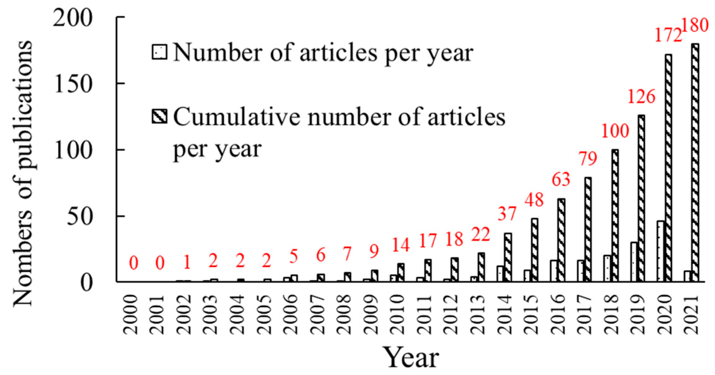
2.1. Literature Search
- Included papers
- Excluded papers
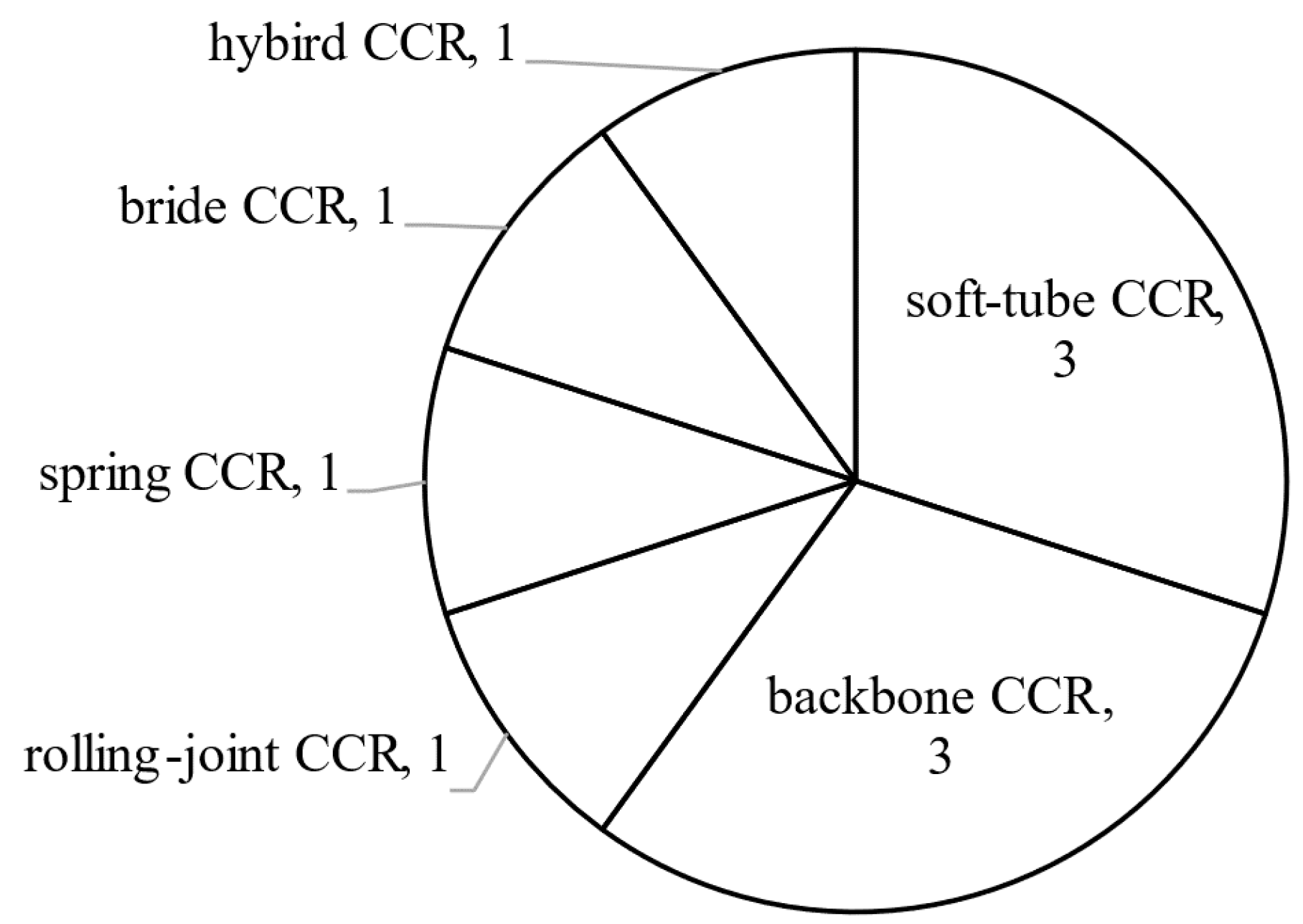
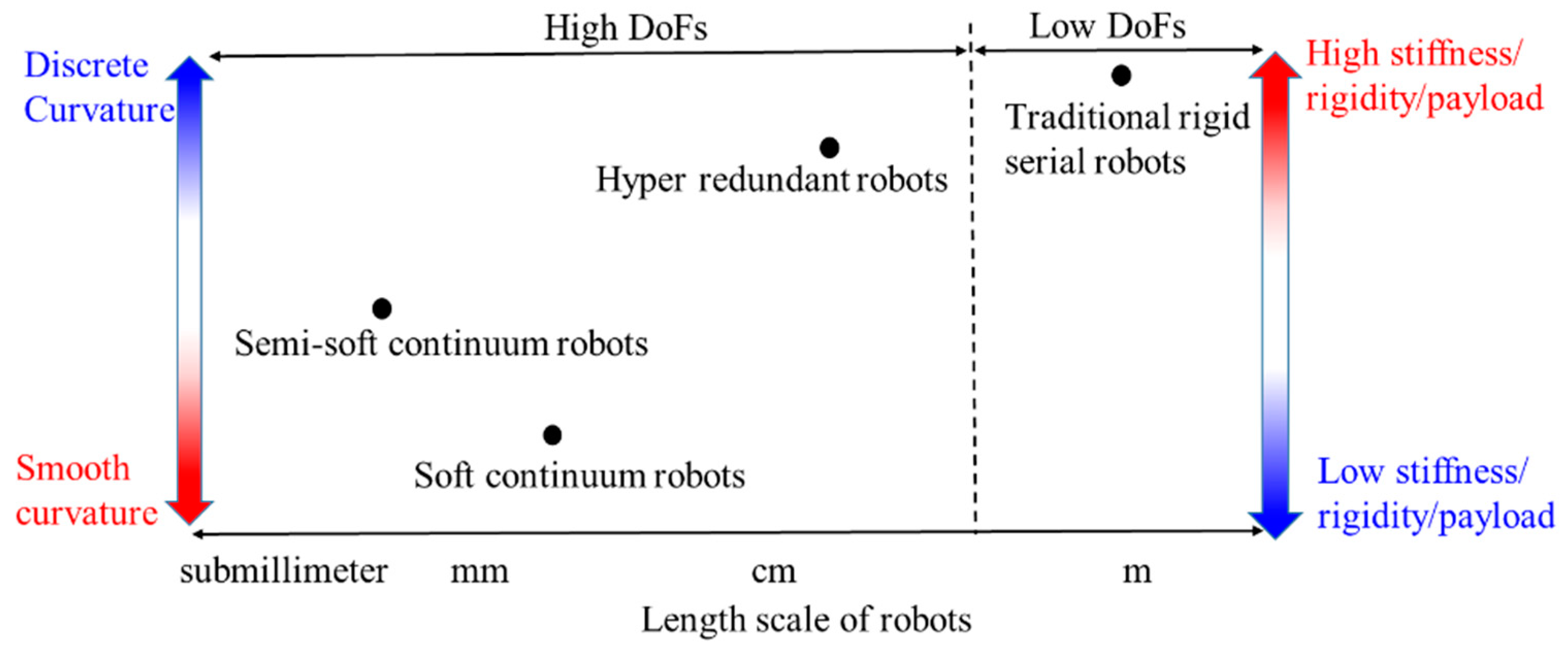
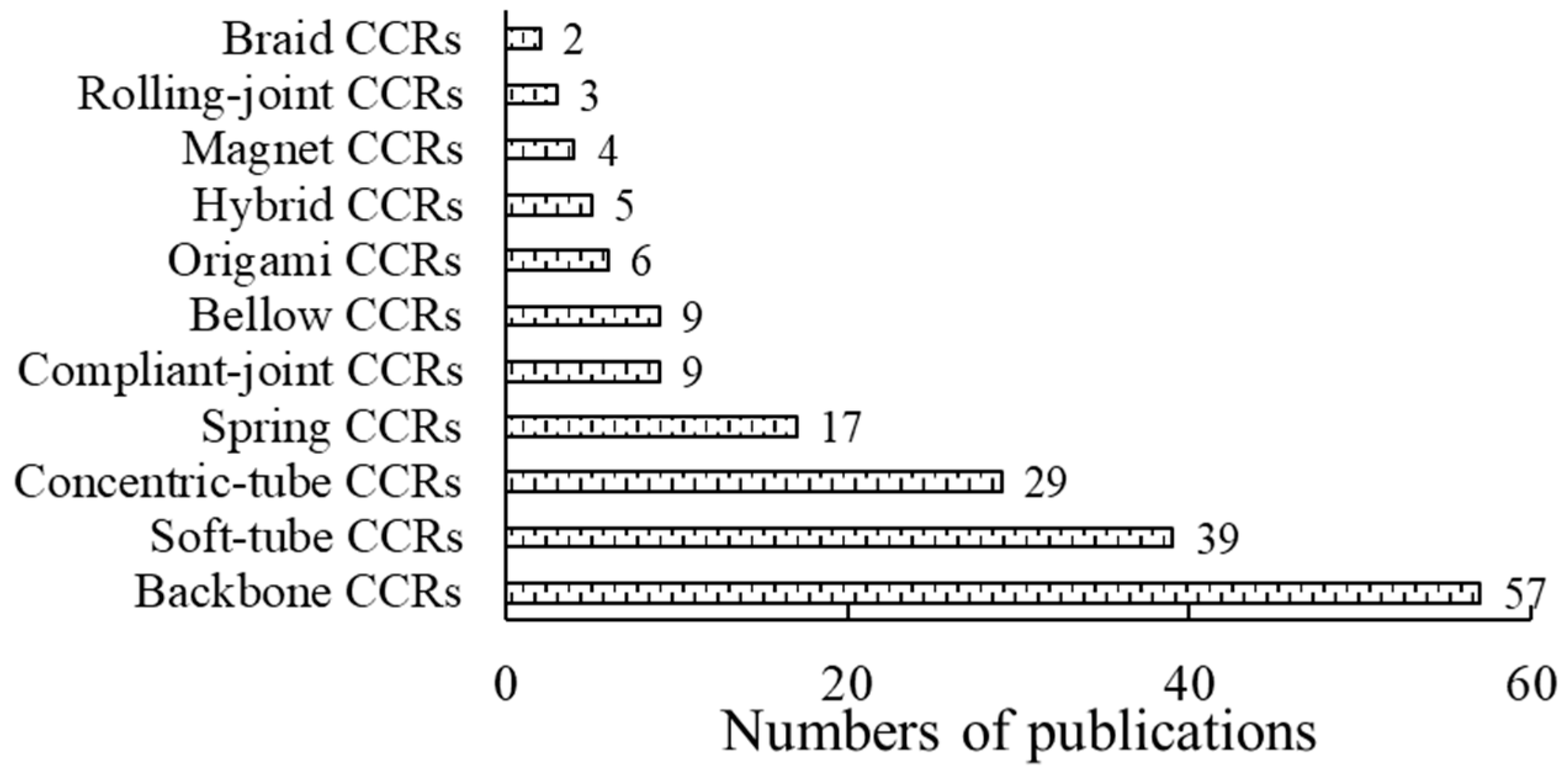
2.2. Trends and Classifications of CCRs
3. Different Basic Transmission Units and Drive Systems
3.1. Basic Transmission Units
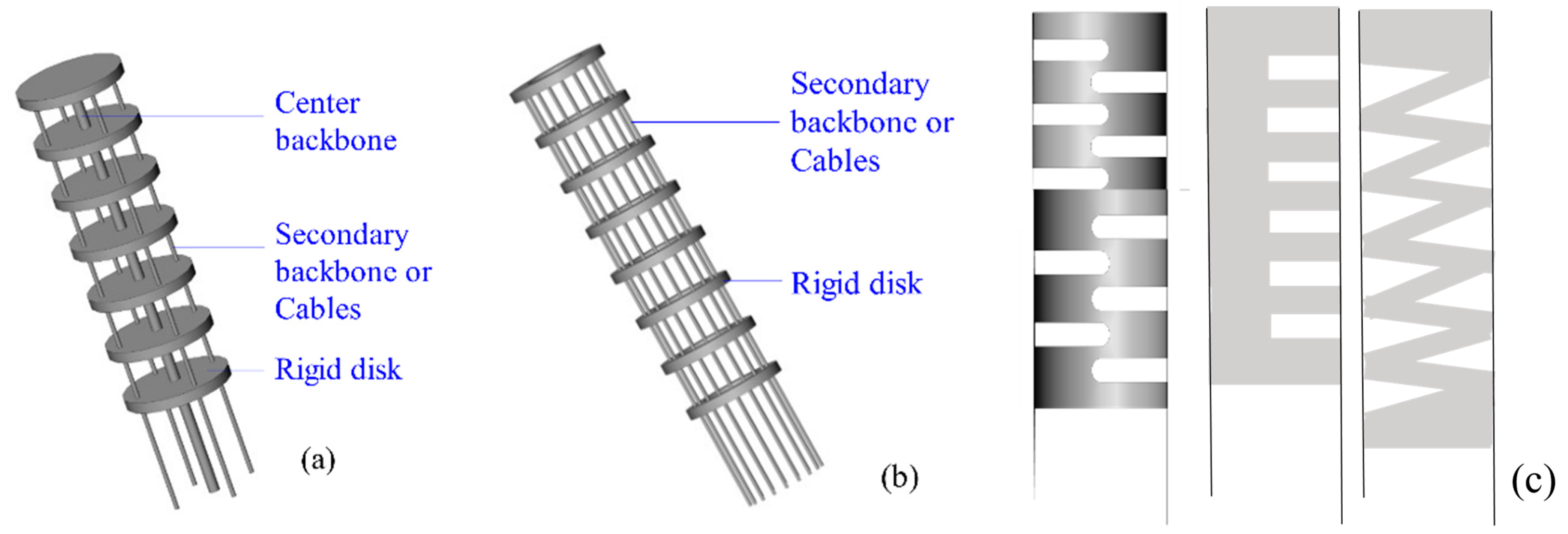
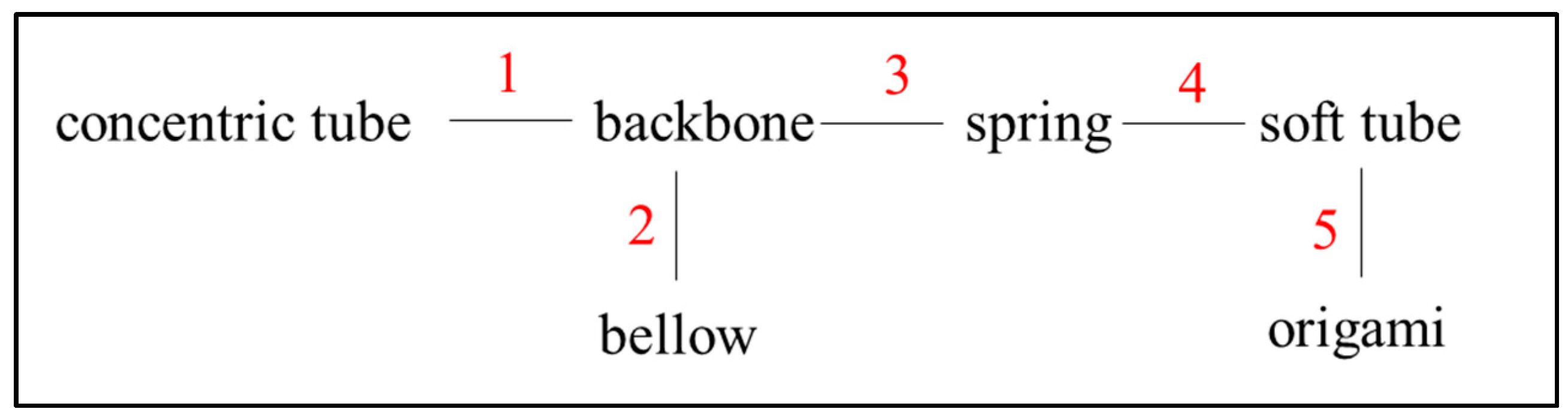
3.1.1. Backbone CCRs
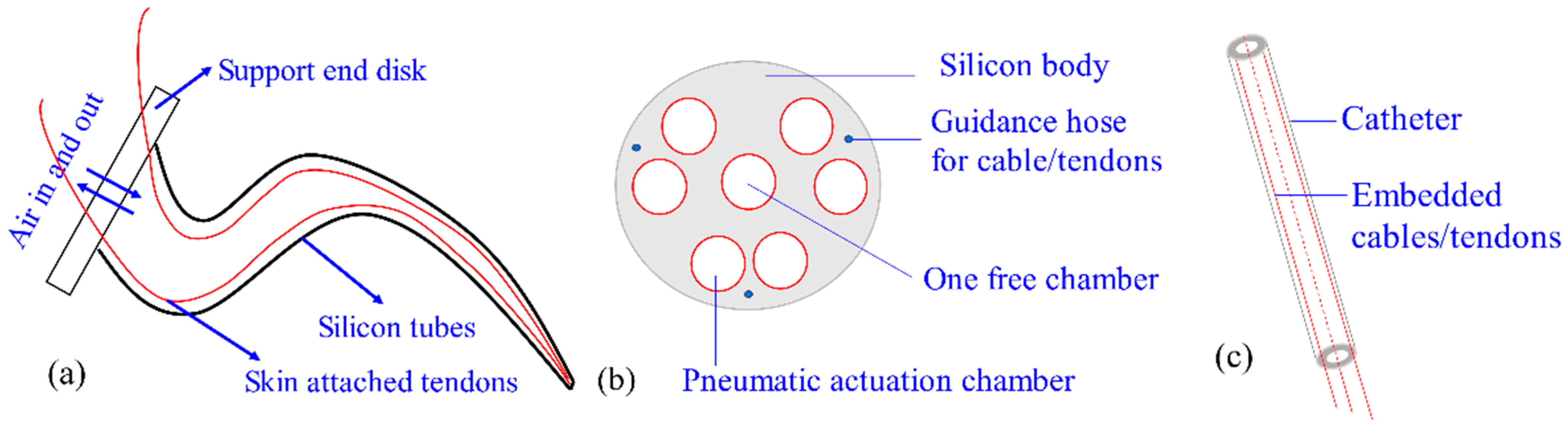
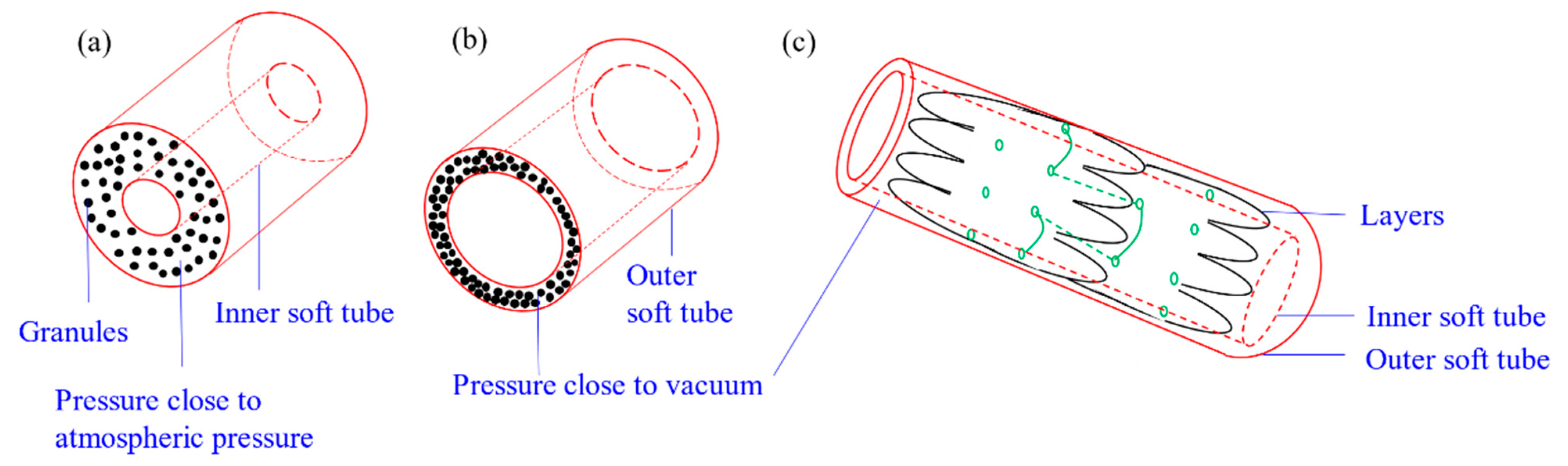
3.1.2. Soft-Tube CCRs
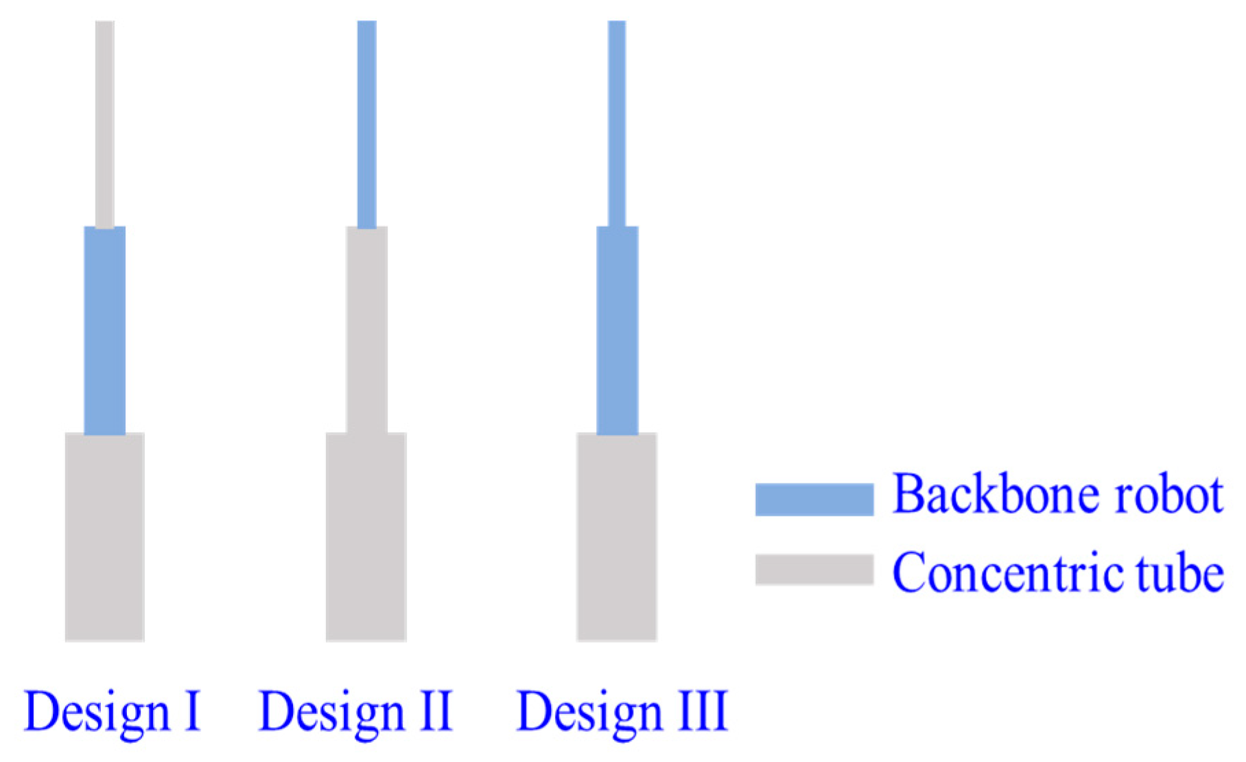
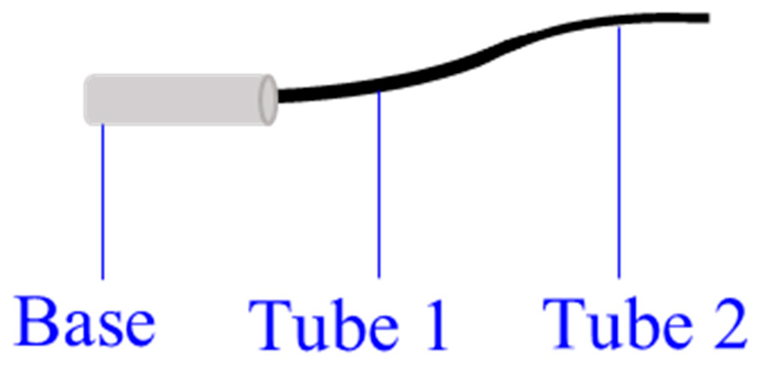
3.1.3. Concentric-Tube CCRs
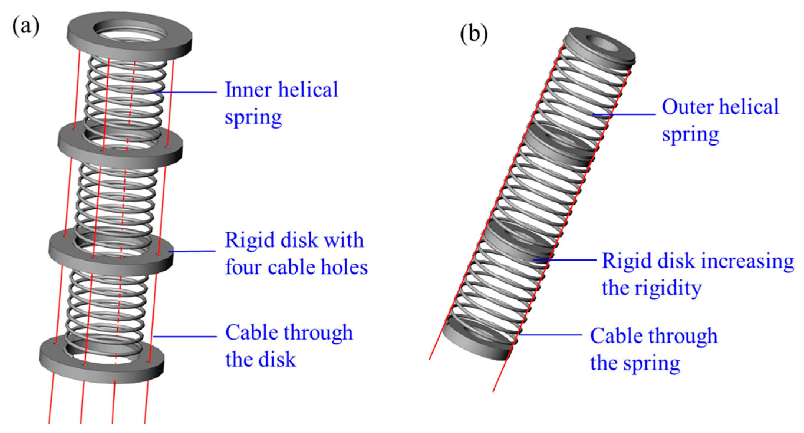
3.1.4. Spring CCRs
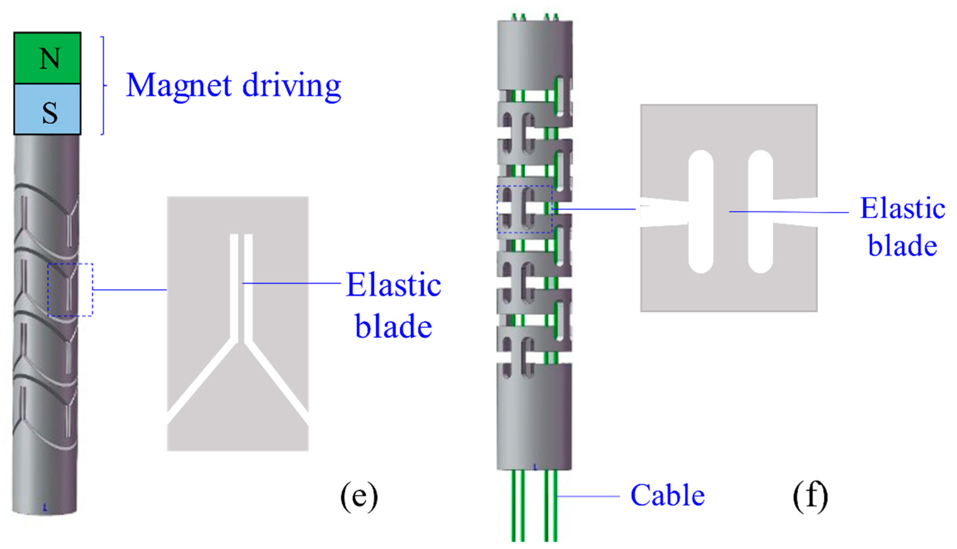
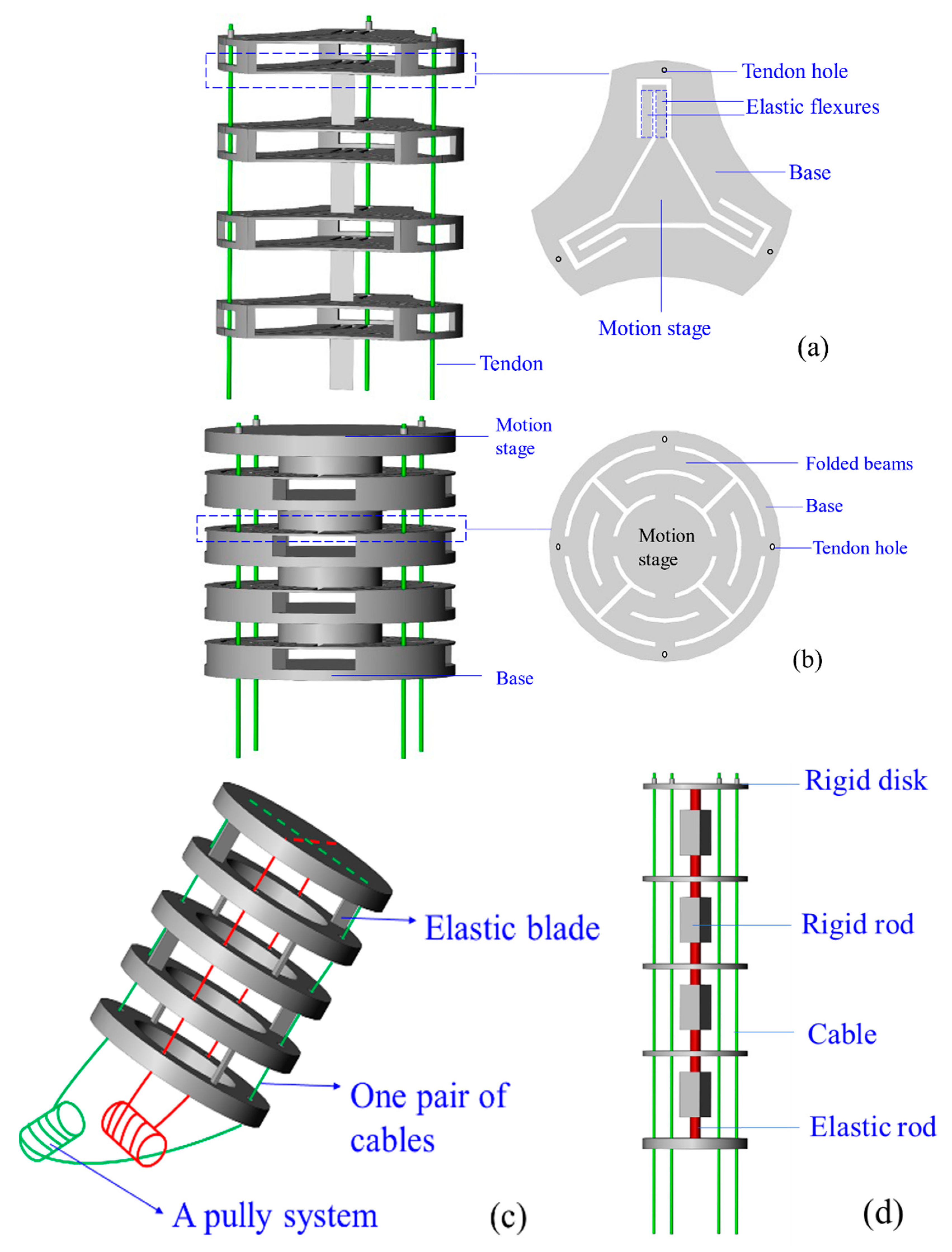
3.1.5. Compliant-Joint CCRs
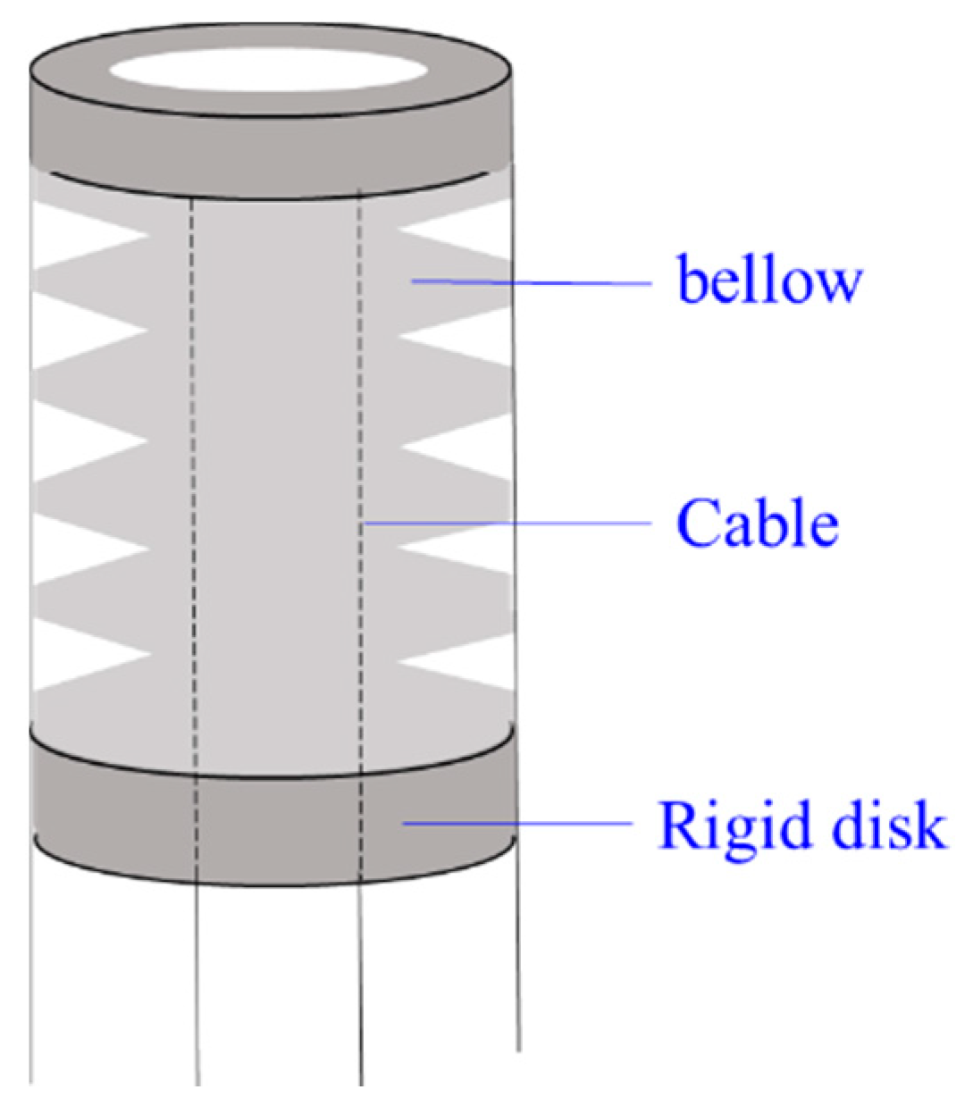
3.1.6. Bellow CCRs
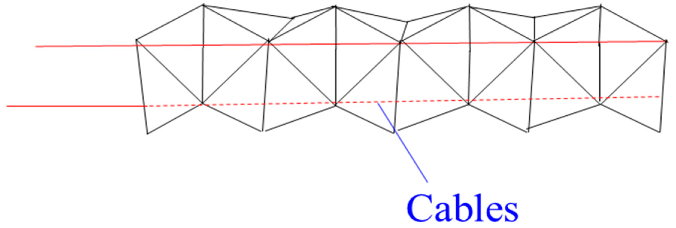
3.1.7. Origami CCRs
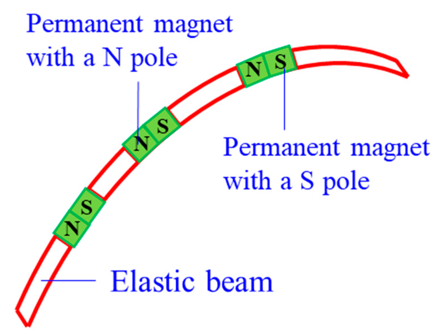
3.1.8. Magnet CCRs
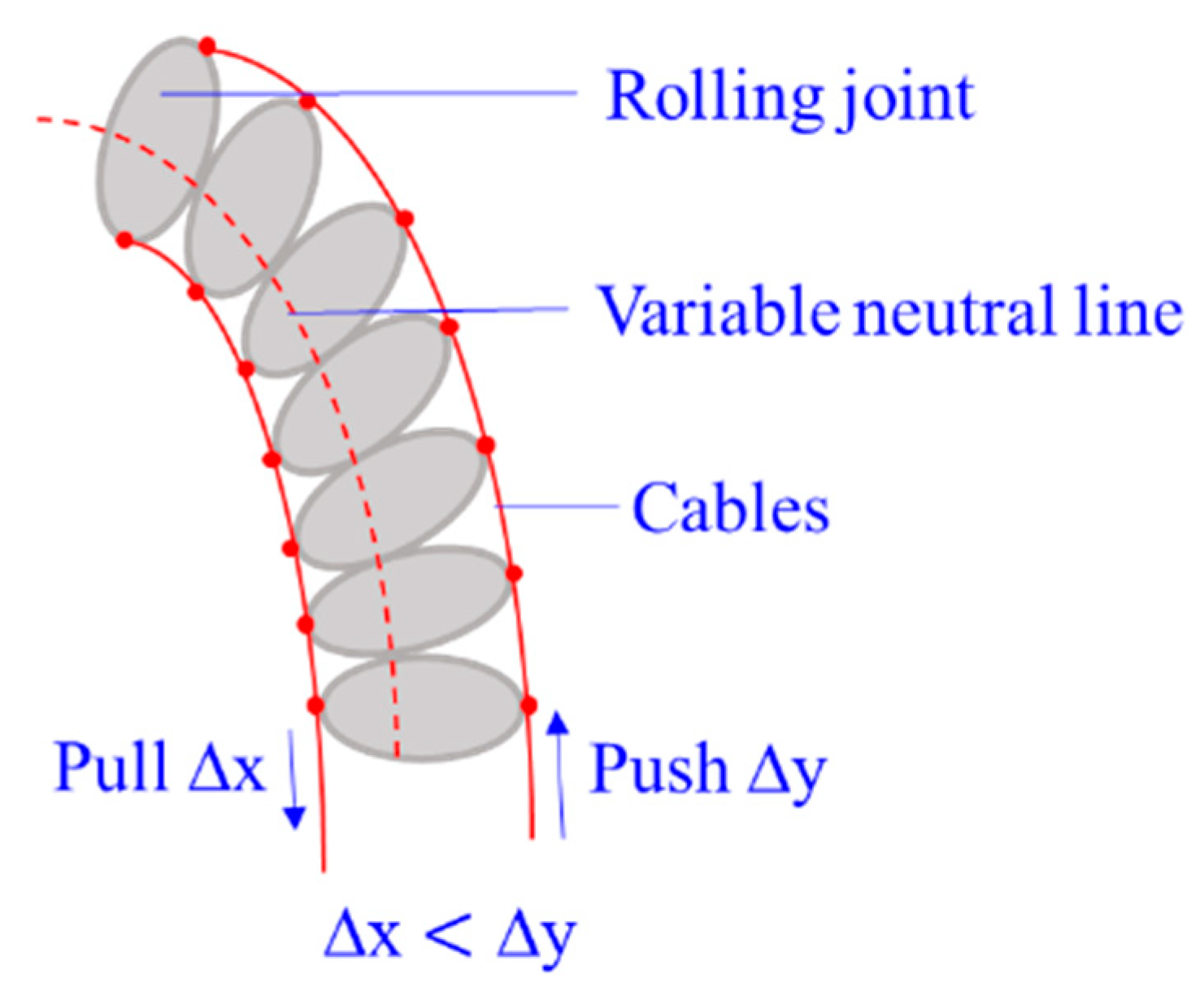
3.1.9. Rolling-Joint CCRs
3.1.10. Braid CCRs
3.1.11. Hybrid CCRs
- Backbone-Concentric-Tube CCR
- Backbone-Bellow CCR
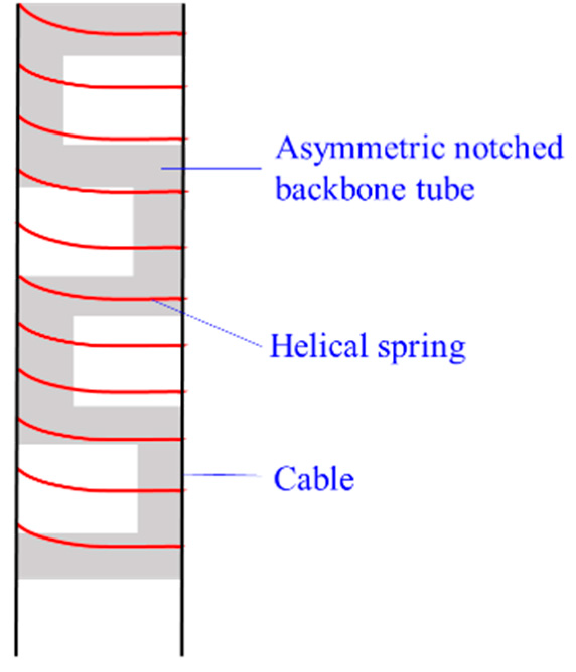
- Notched Backbone-Spring CCR
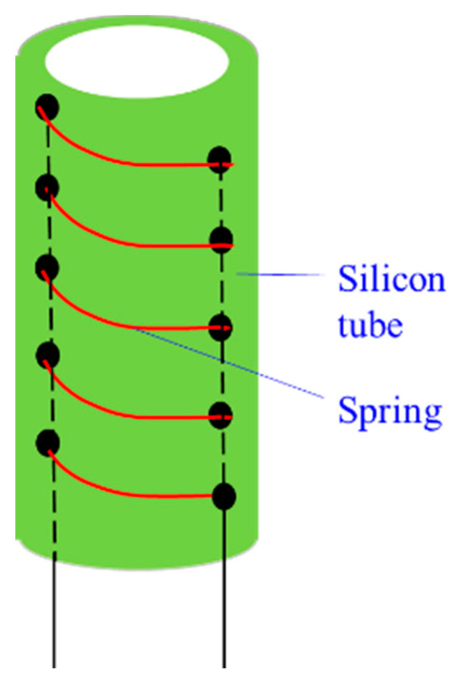
- Soft tube-Spring CCR
- Soft tube-Origami manipulator
3.2. Drive Systems
4. Stiffness and Sensing Systems
4.1. Stiffness
4.1.1. Applying Dimension Jamming
4.1.2. Using Special Alloys
4.1.3. Designing the Mechanism of the CCR
4.1.4. Actuating the CCR Antagonistically
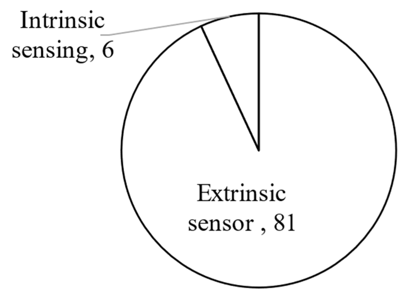
4.2. Sensing Systems
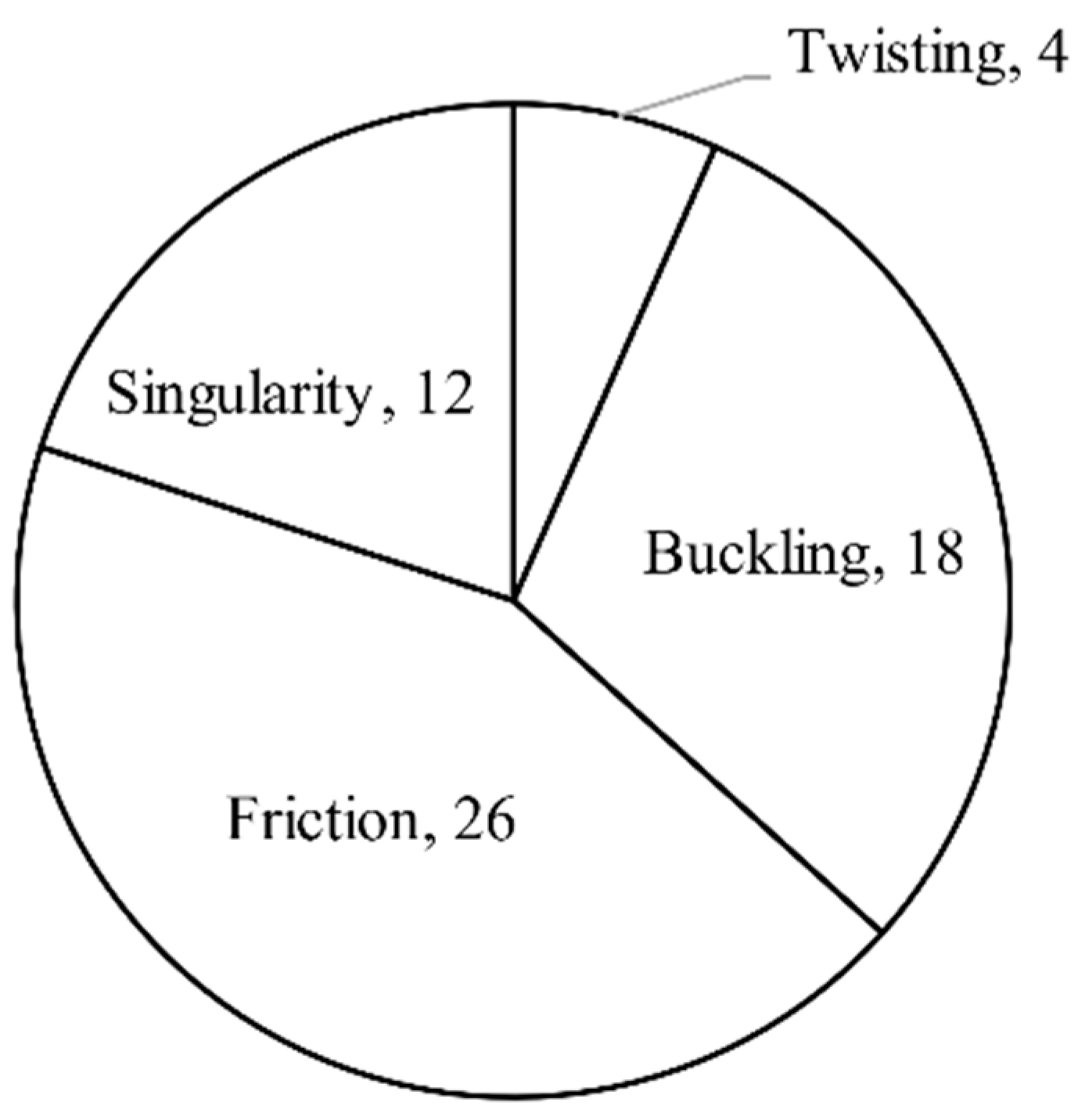
5. Problems of Different CCRs
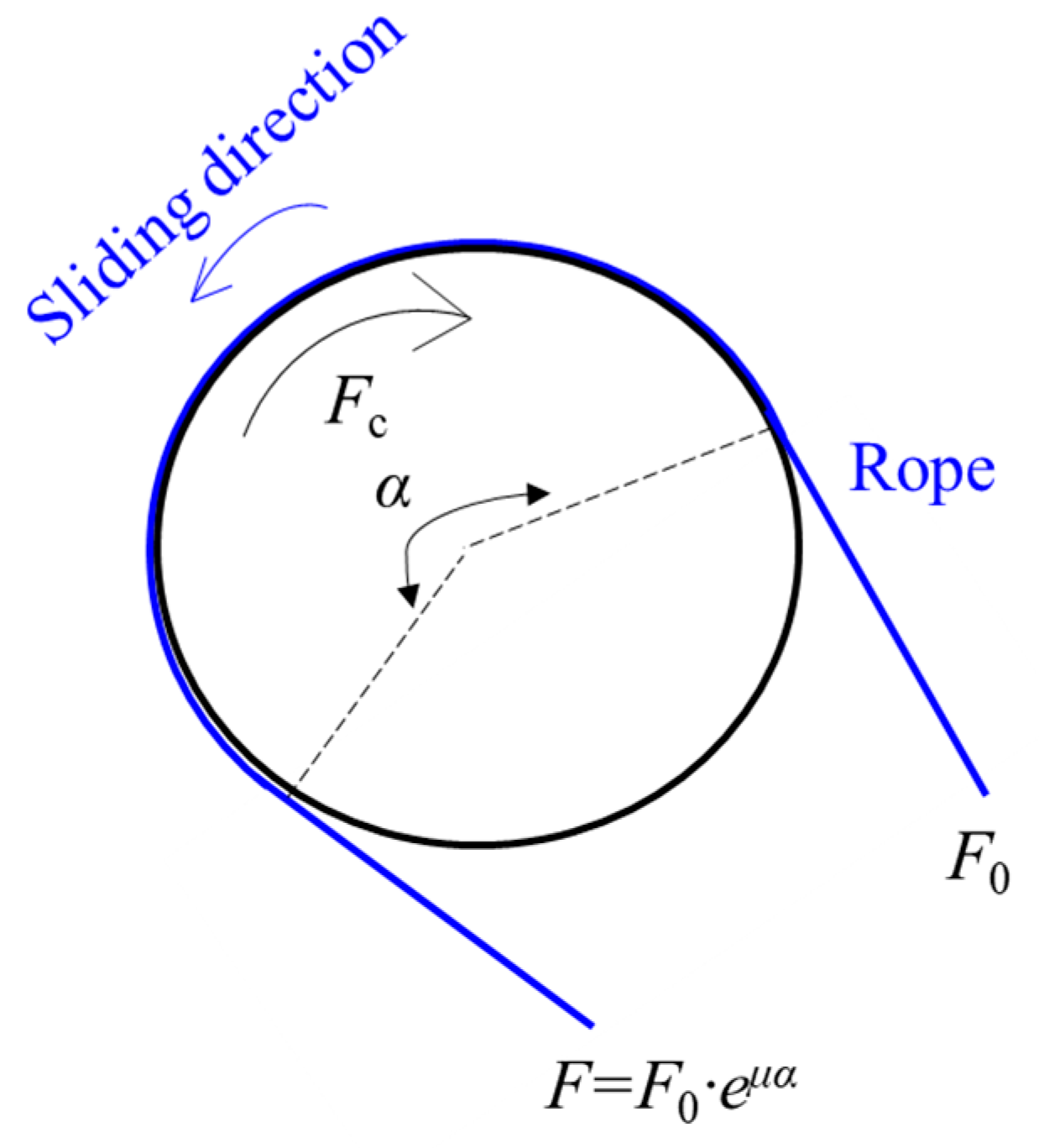
5.1. Friction
5.1.1. Coulomb Friction Model
5.1.2. Capstan Friction Model
5.1.3. Dahl Friction Model
5.2. Buckling
5.2.1. Controlling the Parameter Related to Buckling in the Model
5.2.2. Increasing Rigidity of the CCR
5.2.3. Using Actuation Redundancy
5.2.4. Keeping Applied Loads under the Critical Force
5.3. Singularity
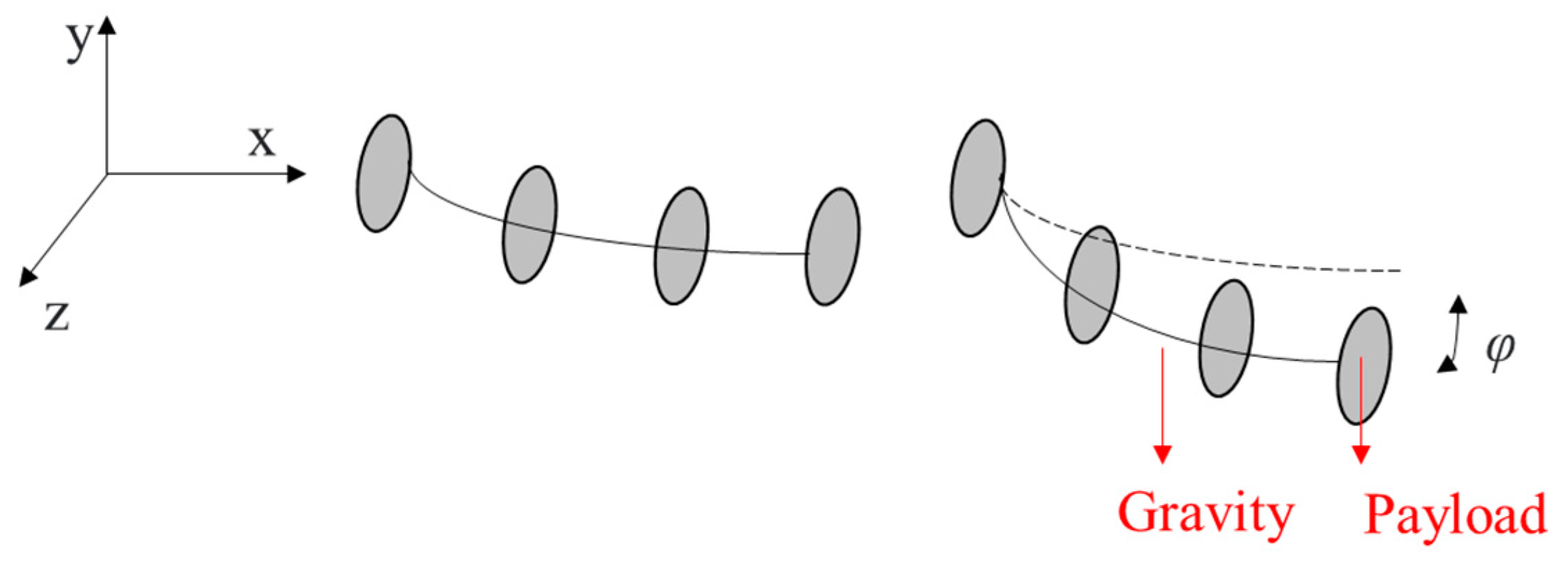
5.4. Twisting
6. Summary and Perspectives
- Design of CCRs
- Collaborative CCRs
- Actuation redundancy and compensation
- Stress consideration
- Obstacle avoidance
Author Contributions
Funding
Institutional Review Board Statement
Informed Consent Statement
Acknowledgments
Conflicts of Interest
References
- Xu, K.; Simaan, N. An Investigation of the Intrinsic Force Sensing Capabilities of Continuum Robots. IEEE Trans. Robot. 2008, 24, 576–587. [Google Scholar] [CrossRef]
- Moses, M.S.; Murphy, R.J.; Kutzer, M.D.M.; Armand, M. Modeling Cable and Guide Channel Interaction in a High-Strength Cable-Driven Continuum Manipulator. IEEE/ASME Trans. Mechatron. 2015, 20, 2876–2889. [Google Scholar] [CrossRef] [PubMed] [Green Version]
- Wang, L.; Simaan, N. Geometric Calibration of Continuum Robots: Joint Space and Equilibrium Shape Deviations. IEEE Trans. Robot. 2019, 35, 387–402. [Google Scholar] [CrossRef]
- Zheng, T.; Branson, D.T.; Guglielmino, E.; Kang, R.; Cerda, G.A.M.; Cianchetti, M.; Follador, M.; Godage, I.S.; Caldwell, D.G. Model Validation of an Octopus Inspired Continuum Robotic Arm for Use in Underwater Environments. J. Mech. Robot. 2013, 5, 021004. [Google Scholar] [CrossRef]
- Marchese, A.D.; Katzschmann, R.; Rus, D.L. A Recipe for Soft Fluidic Elastomer Robots. Soft Robot. 2015, 2, 7–25. [Google Scholar] [CrossRef] [Green Version]
- Bajo, A.; Simaan, N. Hybrid motion/force control of multi-backbone continuum robots. Int. J. Robot. Res. 2015, 35, 422–434. [Google Scholar] [CrossRef]
- Yip, M.C.; Camarillo, D.B. Model-Less Hybrid Position/Force Control: A Minimalist Approach for Continuum Manipulators in Unknown, Constrained Environments. IEEE Robot. Autom. Lett. 2016, 1, 844–851. [Google Scholar] [CrossRef]
- Alambeigi, F.; Bakhtiarinejad, M.; Sefati, S.; Hegeman, R.; Iordachita, I.; Khanuja, H.; Armand, M. On the Use of a Continuum Manipulator and a Bendable Medical Screw for Minimally Invasive Interventions in Orthopedic Surgery. IEEE Trans. Med. Robot. Bionics 2019, 1, 14–21. [Google Scholar] [CrossRef]
- Roy, R.; Wang, L.; Simaan, N. Modeling and Estimation of Friction, Extension, and Coupling Effects in Multisegment Continuum Robots. IEEE/ASME Trans. Mechatron. 2016, 22, 909–920. [Google Scholar] [CrossRef]
- Gao, A.; Murphy, R.J.; Liu, H.; Iordachita, I.I.; Armand, M. Mechanical Model of Dexterous Continuum Manipulators With Compliant Joints and Tendon/External Force Interactions. IEEE/ASME Trans. Mechatron. 2017, 22, 465–475. [Google Scholar] [CrossRef]
- Kato, T.; Okumura, I.; Song, S.-E.; Golby, A.J.; Hata, N. Tendon-Driven Continuum Robot for Endoscopic Surgery: Preclinical Development and Validation of a Tension Propagation Model. IEEE/ASME Trans. Mechatron. 2015, 20, 2252–2263. [Google Scholar] [CrossRef] [Green Version]
- Zhang, X.; Li, W.; Chiu, P.W.-Y.; Li, Z. A Novel Flexible Robotic Endoscope With Constrained Tendon-Driven Continuum Mechanism. IEEE Robot. Autom. Lett. 2020, 5, 1366–1372. [Google Scholar] [CrossRef]
- Dong, X.; Axinte, D.; Palmer, D.; Cobos, S.; Raffles, M.; Rabani, A.; Kell, J. Development of a slender continuum robotic system for on-wing inspection/repair of gas turbine engines. Robot. Comput. Manuf. 2017, 44, 218–229. [Google Scholar] [CrossRef] [Green Version]
- Hannan, M.W.; Walker, I.D. Analysis and experiments with an elephant’s trunk robot. Adv. Robot. 2001, 15, 847–858. [Google Scholar] [CrossRef]
- Zheng, T.; Branson, D.T.; Kang, R.; Cianchetti, M.; Guglielmino, E.; Follador, M.; Medrano-Cerda, G.A.; Godage, I.S.; Caldwell, D.G. Dynamic continuum arm model for use with underwater robotic manipulators inspired by octopus vulgaris. In Proceedings of the 2012 IEEE International Conference on Robotics and Automation, Saint Paul, MN, USA, 14–18 May 2012; Institute of Electrical and Electronics Engineers (IEEE): Piscataway, NJ, USA, 2012; pp. 5289–5294. [Google Scholar]
- Porter, M.M.; Adriaens, D.; Hatton, R.L.; Meyers, M.A.; McKittrick, J. Why the seahorse tail is square. Science 2015, 349. [Google Scholar] [CrossRef] [PubMed] [Green Version]
- Li, L.; Jin, T.; Tian, Y.; Yang, F.; Xi, F. Design and Analysis of a Square-Shaped Continuum Robot With Better Grasping Ability. IEEE Access 2019, 7, 57151–57162. [Google Scholar] [CrossRef]
- Webster, I.R.J.; Romano, J.M.; Cowan, N.J. Mechanics of Precurved-Tube Continuum Robots. IEEE Trans. Robot. 2009, 25, 67–78. [Google Scholar] [CrossRef]
- Mehling, J.S.; Diftler, M.A.; Chu, M.; Valvo, M.C. A Minimally Invasive Tendril Robot for In-Space Inspection. In Proceedings of the First IEEE/RAS-EMBS International Conference on Biomedical Robotics and BioMechatron, 2006. BioRob 2006, Pisa, Italy, 20–22 February 2006. [Google Scholar] [CrossRef]
- Dong, X.; Raffles, M.; Cobos-Guzmán, S.; Axinte, D.; Kell, J. A Novel Continuum Robot Using Twin-Pivot Compliant Joints: Design, Modeling, and Validation. J. Mech. Robot. 2015, 8, 021010. [Google Scholar] [CrossRef]
- Xu, W.; Liu, T.; Li, Y. Kinematics, Dynamics, and Control of a Cable-Driven Hyper-Redundant Manipulator. IEEE/ASME Trans. Mech. 2018, 23, 1693–1704. [Google Scholar] [CrossRef]
- Xu, W.; Meng, D.; Liu, H.; Wang, X.; Liang, B. Singularity-Free Trajectory Planning of Free-Floating Multiarm Space Robots for Keeping the Base Inertially Stabilized. IEEE Trans. Syst. Man Cybern. Syst. 2017, 49, 2464–2477. [Google Scholar] [CrossRef]
- Kim, Y.; Parada, G.A.; Liu, S.; Zhao, X. Ferromagnetic soft continuum robots. Sci. Robot. 2019, 4, eaax7329. [Google Scholar] [CrossRef]
- Majidi, C. Soft Robotics: A Perspective—Current Trends and Prospects for the Future. Soft Robot. 2014, 1, 5–11. [Google Scholar] [CrossRef]
- Burgner-Kahrs, J.; Rucker, D.C.; Choset, H. Continuum Robots for Medical Applications: A Survey. IEEE Trans. Robot. 2015, 31, 1261–1280. [Google Scholar] [CrossRef]
- Runciman, M.; Darzi, A.; Mylonas, G.P. Soft Robotics in Minimally Invasive Surgery. Soft Robot. 2019, 6, 423–443. [Google Scholar] [CrossRef] [Green Version]
- Kolachalama, S.; Lakshmanan, S. Continuum Robots for Manipulation Applications: A Survey. J. Robot. 2020, 2020, 1–19. [Google Scholar] [CrossRef]
- Hannan, M.W.; Walker, I.D. Kinematics and the Implementation of an Elephant’s Trunk Manipulator and Other Continuum Style Robots. J. Robot. Syst. 2003, 20, 45–63. [Google Scholar] [CrossRef]
- Shen, W.; Yang, G.; Zheng, T.; Wang, Y.; Yang, K.; Fang, Z. An Accuracy Enhancement Method for a Cable-Driven Continuum Robot With a Flexible Backbone. IEEE Access 2020, 8, 37474–37481. [Google Scholar] [CrossRef]
- Langer, M.; Amanov, E.; Burgner-Kahrs, J. Stiffening Sheaths for Continuum Robots. Soft Robot. 2018, 5, 291–303. [Google Scholar] [CrossRef]
- Ouyang, B.; Liu, Y.; Tam, H.Y.; Sun, N. Design of an Interactive Control System for a Multisection Continuum Robot. IEEE/ASME Trans. Mechatron. 2018, 23, 2379–2389. [Google Scholar] [CrossRef]
- Case, J.C.; White, E.L.; SunSpiral, V.; Kramer-Bottiglio, R. Reducing Actuator Requirements in Continuum Robots Through Optimized Cable Routing. Soft Robot. 2018, 5, 109–118. [Google Scholar] [CrossRef] [PubMed]
- Oliver-Butler, K.; Till, J.; Rucker, C. Continuum Robot Stiffness Under External Loads and Prescribed Tendon Displacements. IEEE Trans. Robot. 2019, 35, 403–419. [Google Scholar] [CrossRef]
- Ma, X.; Song, C.; Chiu, W.Y.P.; Li, Z. Autonomous Flexible Endoscope for Minimally Invasive Surgery With Enhanced Safety. IEEE Robot. Autom. Lett. 2019, 4, 2607–2613. [Google Scholar] [CrossRef]
- Gravagne, I.A.; Rahn, C.D.; Walker, I.D.; Member, S. Large Deflection Dynamics and Control for Planar Continuum Robots. IEEE/ASME Trans. Mechatron. 2003, 8, 299–307. [Google Scholar] [CrossRef] [Green Version]
- Rucker, D.C.; Webster, R.J. Statics and dynamics of continuum robots with general tendon routing and external loading. IEEE Trans. Robot. 2011, 27, 1033–1044. [Google Scholar] [CrossRef]
- Gravagne, I.A.; Walker, I.D. Manipulability, force, and compliance analysis for planar continuum manipulators. IEEE Trans. Robot. Autom. 2002, 18, 263–273. [Google Scholar] [CrossRef] [Green Version]
- Chikhaoui, M.T.; Lilge, S.; Kleinschmidt, S.; Burgner-Kahrs, J. Comparison of Modeling Approaches for a Tendon Actuated Continuum Robot With Three Extensible Segments. IEEE Robot. Autom. Lett. 2019, 4, 989–996. [Google Scholar] [CrossRef]
- Xu, K.; Zhao, J.; Qiu, D.; Wang, Y. A Pilot Study of a Continuum Shoulder Exoskeleton for Anatomy Adaptive Assistances. J. Mech. Robot. 2014, 6, 041011. [Google Scholar] [CrossRef]
- Rone, W.S.; Ben-Tzvi, P. Mechanics Modeling of Multisegment Rod-Driven Continuum Robots. J. Mech. Robot. 2014, 6, 041006. [Google Scholar] [CrossRef] [Green Version]
- Goldman, R.E.; Bajo, A.; Simaan, N. Compliant Motion Control for Multisegment Continuum Robots With Actuation Force Sensing. IEEE Trans. Robot. 2014, 30, 890–902. [Google Scholar] [CrossRef]
- Rone, W.S.; Ben-Tzvi, P. Continuum Robot Dynamics Utilizing the Principle of Virtual Power. IEEE Trans. Robot. 2014, 30, 275–287. [Google Scholar] [CrossRef]
- Xu, K.; Zhao, J.; Fu, M. Development of the SJTU Unfoldable Robotic System (SURS) for Single Port Laparoscopy. IEEE/ASME Trans. Mechatron. 2014, 20, 2133–2145. [Google Scholar] [CrossRef]
- Li, Z.; Zin Oo, M.; Nalam, V.; Duc Thang, V.; Ren, H.; Kofidis, T.; Yu, H. Design of a novel flexible endoscope-cardioscope. J. Mech. Robot. 2016, 8, 1–9. [Google Scholar] [CrossRef] [Green Version]
- Yuan, H.; Chiu, P.W.Y.; Li, Z. Shape-Reconstruction-Based Force Sensing Method for Continuum Surgical Robots With Large Deformation. IEEE Robot. Autom. Lett. 2017, 2, 1972–1979. [Google Scholar] [CrossRef]
- Yoshida, S.; Kanno, T.; Kawashima, K. Surgical Robot With Variable Remote Center of Motion Mechanism Using Flexible Structure. J. Mech. Robot. 2018, 10, 031011. [Google Scholar] [CrossRef]
- Du, Z.; Yang, W.; Dong, W. Kinematics Modeling of a Notched Continuum Manipulator. J. Mech. Robot. 2015, 7, 041017. [Google Scholar] [CrossRef]
- Kutzer, M.D.; Segreti, S.M.; Brown, C.Y.; Armand, M.; Taylor, R.H.; Mears, S.C. Design of a new cable-driven manipulator with a large open lumen: Preliminary applications in the minimally-invasive removal of osteolysis. In Proceedings of the 2011 IEEE International Conference on Robotics and Automation, Shanghai, China, 9–13 May 2011. [Google Scholar] [CrossRef]
- Zhao, B.; Zeng, L.; Wu, Z.; Xu, K. A continuum manipulator for continuously variable stiffness and its stiffness control formulation. Mech. Mach. Theory 2020, 149, 103746. [Google Scholar] [CrossRef]
- Xu, K.; Fu, M.; Zhao, J. An experimental kinestatic comparison between continuum manipulators with structural variations. In Proceedings of the 2014 IEEE International Conference on Robotics and Automation (ICRA), Hong Kong, China, 31 May–7 June 2014; Institute of Electrical and Electronics Engineers (IEEE): Piscataway, NJ, USA, 2014; pp. 3258–3264. [Google Scholar]
- He, B.; Wang, Z.; Li, Q.; Xie, H.; Shen, R. An Analytic Method for the Kinematics and Dynamics of a Multiple-Backbone Continuum Robot. Int. J. Adv. Robot. Syst. 2013, 10, 84. [Google Scholar] [CrossRef]
- Guo, H.; Ju, F.; Cao, Y.; Qi, F.; Bai, D.; Wang, Y.; Chen, B. Continuum robot shape estimation using permanent magnets and magnetic sensors. Sens. Actuators A Phys. 2019, 285, 519–530. [Google Scholar] [CrossRef]
- Ouyang, B.; Liu, Y.; Sun, D. Design of a three-segment continuum robot for minimally invasive surgery. Robot. Biomim. 2016, 3, 43. [Google Scholar] [CrossRef] [Green Version]
- Renda, F.; Giorelli, M.; Calisti, M.; Cianchetti, M.; Laschi, C. Dynamic Model of a Multibending Soft Robot Arm Driven by Cables. IEEE Trans. Robot. 2014, 30, 1109–1122. [Google Scholar] [CrossRef]
- Shiva, A.; Stilli, A.; Noh, Y.; Faragasso, A.; De Falco, I.; Gerboni, G.; Cianchetti, M.; Menciassi, A.; Althoefer, K.; Wurdemann, H.A. Tendon-Based Stiffening for a Pneumatically Actuated Soft Manipulator. IEEE Robot. Autom. Lett. 2016, 1, 632–637. [Google Scholar] [CrossRef] [Green Version]
- Dalvand, M.M.; Nahavandi, S.; Howe, R.D. An Analytical Loading Model for n-Tendon Continuum Robots. IEEE Trans. Robot. 2018, 34, 1215–1225. [Google Scholar] [CrossRef]
- Zhang, Z.; Dequidt, J.; Back, J.; Liu, H.; Duriez, C. Motion Control of Cable-Driven Continuum Catheter Robot Through Contacts. IEEE Robot. Autom. Lett. 2019, 4, 1852–1859. [Google Scholar] [CrossRef]
- Kang, R.; Guglielmino, E.; Zullo, L.; Branson, D.T.; Godage, I.; Caldwell, D.G. Embodiment design of soft continuum robots. Adv. Mech. Eng. 2016, 8, 1–13. [Google Scholar] [CrossRef] [Green Version]
- Kang, R.; Guo, Y.; Chen, L.; Branson, D.T.; Dai, J.S. Design of a Pneumatic Muscle Based Continuum Robot With Embedded Tendons. IEEE/ASME Trans. Mech. 2016, 22, 751–761. [Google Scholar] [CrossRef] [Green Version]
- Li, M.; Kang, R.; Branson, D.T.; Dai, J.S. Model-Free Control for Continuum Robots Based on an Adaptive Kalman Filter. IEEE/ASME Trans. Mechatron. 2017, 23, 286–297. [Google Scholar] [CrossRef]
- Wang, Y.; Gregory, C.; Minor, M.A. Improving Mechanical Properties of Molded Silicone Rubber for Soft Robotics Through Fabric Compositing. Soft Robot. 2018, 5, 272–290. [Google Scholar] [CrossRef]
- Camarillo, D.B.; Milne, C.F.; Carlson, C.R.; Zinn, M.R.; Salisbury, J.K. Mechanics Modeling of Tendon-Driven Continuum Manipulators. IEEE Trans. Robot. 2008, 24, 1262–1273. [Google Scholar] [CrossRef]
- Hasanzadeh, S.; Janabi-Sharifi, F. An Efficient Static Analysis of Continuum Robots. J. Mech. Robot. 2014, 6, 031011. [Google Scholar] [CrossRef]
- Lotfavar, A.; Hasanzadeh, S.; Janabi-Sharifi, F. Cooperative Continuum Robots: Concept, Modeling, and Workspace Analysis. IEEE Robot. Autom. Lett. 2017, 3, 426–433. [Google Scholar] [CrossRef]
- Yu, B.; Fernández, J.D.G.; Tan, T. Probabilistic Kinematic Model of a Robotic Catheter for 3D Position Control. Soft Robot. 2019, 6, 184–194. [Google Scholar] [CrossRef] [PubMed]
- Webster, R.J.; Okamura, A.M.; Cowan, N.J. Toward Active Cannulas: Miniature Snake-Like Surgical Robots. In Proceedings of the 2006 IEEE/RSJ International Conference on Intelligent Robots and Systems, Beijing, China, 9–15 October 2006; pp. 2857–2863. [Google Scholar] [CrossRef]
- Morimoto, T.K.; Okamura, A.M. Design of 3-D Printed Concentric Tube Robots. IEEE Trans. Robot. 2016, 32, 1419–1430. [Google Scholar] [CrossRef] [PubMed]
- Bergeles, C.; Gosline, A.H.; Vasilyev, N.V.; Codd, P.J.; Del Nido, P.J.; Dupont, P.E. Concentric Tube Robot Design and Optimization Based on Task and Anatomical Constraints. IEEE Trans. Robot. 2015, 31, 67–84. [Google Scholar] [CrossRef] [Green Version]
- Dupont, P.E.; Lock, J.; Itkowitz, B.; Butler, E.J. Design and Control of Concentric-Tube Robots. IEEE Trans. Robot. 2010, 26, 209–225. [Google Scholar] [CrossRef] [PubMed] [Green Version]
- Hendrick, R.J.; Gilbert, H.B.; Webster, R.J. Designing snap-free concentric tube robots: A local bifurcation approach. In Proceedings of the 2015 IEEE International Conference on Robotics and Automation (ICRA), Seattle, WA, USA, 25–30 May 2015; pp. 2256–2263. [Google Scholar] [CrossRef]
- Gilbert, H.B.; Hendrick, R.J.; Iii, R.J.W. Elastic Stability of Concentric Tube Robots: A Stability Measure and Design Test. IEEE Trans. Robot. 2016, 32, 20–35. [Google Scholar] [CrossRef] [Green Version]
- Rucker, D.C.; Webster, I.R.J.; Chirikjian, G.S.; Cowan, N.J. Equilibrium Conformations of Concentric-tube Continuum Robots. Int. J. Robot. Res. 2010, 29, 1263–1280. [Google Scholar] [CrossRef] [Green Version]
- Kudryavtsev, A.V.; Chikhaoui, M.T.; Liadov, A.; Rougeot, P.; Spindler, F.; Rabenorosoa, K.; Burgner-Kahrs, J.; Tamadazte, B.; Andreff, N. Eye-in-Hand Visual Servoing of Concentric Tube Robots. IEEE Robot. Autom. Lett. 2018, 3, 2315–2321. [Google Scholar] [CrossRef] [Green Version]
- Vandini, A.; Bergeles, C.; Glocker, B.; Giataganas, P.; Yang, G.-Z. Unified Tracking and Shape Estimation for Concentric Tube Robots. IEEE Trans. Robot. 2017, 33, 901–915. [Google Scholar] [CrossRef]
- Xu, R.; Yurkewich, A.; Patel, R.V. Curvature, Torsion, and Force Sensing in Continuum Robots Using Helically Wrapped FBG Sensors. IEEE Robot. Autom. Lett. 2016, 1, 1052–1059. [Google Scholar] [CrossRef]
- Iyengar, K.; Dwyer, G.; Stoyanov, D. Investigating exploration for deep reinforcement learning of concentric tube robot control. Int. J. Comput. Assist. Radiol. Surg. 2020, 15, 1157–1165. [Google Scholar] [CrossRef]
- Su, H.; Li, G.; Rucker, D.C.; Iii, R.J.W.; Fischer, G.S. A Concentric Tube Continuum Robot with Piezoelectric Actuation for MRI-Guided Closed-Loop Targeting. Ann. Biomed. Eng. 2016, 44, 2863–2873. [Google Scholar] [CrossRef]
- Haraguchi, D.; Kanno, T.; Tadano, K.; Kawashima, K. A Pneumatically Driven Surgical Manipulator With a Flexible Distal Joint Capable of Force Sensing. IEEE/ASME Trans. Mechatron. 2015, 20, 2950–2961. [Google Scholar] [CrossRef]
- Li, M.; Kang, R.; Geng, S.; Guglielmino, E. Design and control of a tendon-driven continuum robot. Trans. Inst. Meas. Control. 2018, 40, 3263–3272. [Google Scholar] [CrossRef]
- Yoon, H.-S.; Jeong, J.H.; Yi, B.-J. Image-Guided Dual Master–Slave Robotic System for Maxillary Sinus Surgery. IEEE Trans. Robot. 2018, 34, 1098–1111. [Google Scholar] [CrossRef]
- Santiago, J.L.C.; Godage, I.S.; Gonthina, P.; Walker, I.D. Soft Robots and Kangaroo Tails: Modulating Compliance in Continuum Structures Through Mechanical Layer Jamming. Soft Robot. 2016, 3, 54–63. [Google Scholar] [CrossRef]
- Kim, Y.; Cheng, S.S.; Diakite, M.; Gullapalli, R.P.; Simard, J.M.; Desai, J.P. Toward the Development of a Flexible Mesoscale MRI-Compatible Neurosurgical Continuum Robot. IEEE Trans. Robot. 2017, 33, 1386–1397. [Google Scholar] [CrossRef] [PubMed]
- Gao, A.; Zou, Y.; Wang, Z.; Liu, H. A General Friction Model of Discrete Interactions for Tendon Actuated Dexterous Manipulators. J. Mech. Robot. 2017, 9, 041019. [Google Scholar] [CrossRef]
- Frazelle, C.G.; Kapadia, A.D.; Walker, I.D. A Haptic Continuum Interface for the Teleoperation of Extensible Continuum Manipulators. IEEE Robot. Autom. Lett. 2020, 5, 1875–1882. [Google Scholar] [CrossRef]
- Feng, F.; Hong, W.; Xie, L. Design of 3D-Printed Flexible Joints With Presettable Stiffness for Surgical Robots. IEEE Access 2020, 8, 79573–79585. [Google Scholar] [CrossRef]
- Francis, P.; Eastwood, K.W.; Bodani, V.; Price, K.; Upadhyaya, K.; Podolsky, D.; Azimian, H.; Looi, T.; Drake, J. Miniaturized Instruments for the da Vinci Research Kit: Design and Implementation of Custom Continuum Tools. IEEE Robot. Autom. Mag. 2017, 24, 24–33. [Google Scholar] [CrossRef]
- Thuruthel, T.G.; Falotico, E.; Manti, M.; Pratesi, A.; Cianchetti, M.; Laschi, C. Learning Closed Loop Kinematic Controllers for Continuum Manipulators in Unstructured Environments. Soft Robot. 2017, 4, 285–296. [Google Scholar] [CrossRef] [PubMed]
- Frazelle, C.G.; Kapadia, A.; Walker, I. Developing a Kinematically Similar Master Device for Extensible Continuum Robot Manipulators. ASME J. Mech. Robot. 2018, 10, 025005. [Google Scholar] [CrossRef] [Green Version]
- Yeshmukhametov, A.; Buribayev, Z.; Amirgaliyev, Y.; Ramakrishnan, R.R. Modeling and Validation of New Continuum Robot Backbone Design With Variable Stiffness Inspired from Elephant Trunk. IOP Conf. Series Mater. Sci. Eng. 2018, 417, 012010. [Google Scholar] [CrossRef]
- Hao, G.; Dai, F.; He, X.; Liu, Y. Design and analytical analysis of a large-range tri-symmetrical 2R1T compliant mechanism. Microsyst. Technol. 2017, 23, 4359–4366. [Google Scholar] [CrossRef]
- Simaan, N.; Taylor, R.; Flint, P. A dexterous system for laryngeal surgery. In Proceedings of the IEEE International Conference on Robotics and Automation, 2004. ICRA ’04. 2004, New Orleans, LA, USA, 26 April–1 May 2004. [Google Scholar] [CrossRef]
- Qi, P.; Qiu, C.; Liu, H.; Dai, J.S.; Seneviratne, L.; Althoefer, K.A. A Novel Continuum Manipulator Design Using Serially Connected Double-Layer Planar Springs. IEEE/ASME Trans. Mechatron. 2015, 21, 1281–1292. [Google Scholar] [CrossRef] [Green Version]
- Awtar, S.; Slocum, A.H. Flexure systems based on a symmetric diaphragm flexure. In Proceedings of the ASPE 2005 Annual Meeting, Chicago, IL, USA, 10–14 September 2005. [Google Scholar]
- Dong, X.; Raffles, M.; Guzman, S.C.; Axinte, D.; Kell, J. Design and analysis of a family of snake arm robots connected by compliant joints. Mech. Mach. Theory 2014, 77, 73–91. [Google Scholar] [CrossRef]
- Thomas, T.L.; Venkiteswaran, V.K.; Ananthasuresh, G.K.; Misra, S. A Monolithic Compliant Continuum Manipulator: A Proof-of-Concept Study. J. Mech. Robot. 2020, 12, 1–11. [Google Scholar] [CrossRef]
- Zhang, T.; Ping, Z.; Zuo, S. Miniature Continuum Manipulator with 3-DOF Force Sensing for Retinal Microsurgery. J. Mech. Robot. 2021, 1–34. [Google Scholar] [CrossRef]
- Rolf, M.; Steil, J.J. Efficient Exploratory Learning of Inverse Kinematics on a Bionic Elephant Trunk. IEEE Trans. Neural Netw. Learn. Syst. 2014, 25, 1147–1160. [Google Scholar] [CrossRef]
- Bailly, Y.; Amirat, Y.; Fried, G. Modeling and Control of a Continuum Style Microrobot for Endovascular Surgery. IEEE Trans. Robot. 2011, 27, 1024–1030. [Google Scholar] [CrossRef]
- Walker, I.D. Continuous Backbone ‘Continuum’ Robot Manipulators. ISRN Robot. 2013, 2013, 1–19. [Google Scholar] [CrossRef] [Green Version]
- Kim, S.-J.; Lee, D.-Y.; Jung, G.-P.; Cho, K.-J. An origami-inspired, self-locking robotic arm that can be folded flat. Sci. Robot. 2018, 3, eaar2915. [Google Scholar] [CrossRef] [Green Version]
- Edmondson, B.J.; Bowen, L.A.; Grames, C.L.; Magleby, S.P.; Howell, L.L.; Bateman, T.C. Oriceps: Origami-Inspired Forceps. In Proceedings of the ASME 2013 Conference on Smart Materials, Adaptive Structures and Intelligent Systems. Volume 1: Development and Characterization of Multifunctional Materials; Modeling, Simulation and Control of Adaptive Systems; Integrated System Design and Implementation, Snowbird, UT, USA, 16–18 September 2013. [Google Scholar] [CrossRef]
- Zhang, K.; Qiu, C.; Dai, J.S. An Extensible Continuum Robot With Integrated Origami Parallel Modules. J. Mech. Robot. 2016, 8, 031010. [Google Scholar] [CrossRef]
- Edelmann, J.; Petruska, A.J.; Nelson, B.J. Magnetic control of continuum devices. Int. J. Robot. Res. 2017, 36, 68–85. [Google Scholar] [CrossRef]
- Suh, J.-W.; Kim, K.-Y.; Jeong, J.-W.; Lee, J.-J. Design Considerations for a Hyper-Redundant Pulleyless Rolling Joint With Elastic Fixtures. IEEE/ASME Trans. Mechatron. 2015, 20, 2841–2852. [Google Scholar] [CrossRef]
- Kim, Y.-J.; Cheng, S.; Kim, S.; Iagnemma, K. A Stiffness-Adjustable Hyperredundant Manipulator Using a Variable Neutral-Line Mechanism for Minimally Invasive Surgery. IEEE Trans. Robot. 2014, 30, 382–395. [Google Scholar] [CrossRef] [Green Version]
- Hassan, T.; Cianchetti, M.; Mazzolai, B.; Laschi, C.; Dario, P. Active-Braid, a Bioinspired Continuum Manipulator. IEEE Robot. Autom. Lett. 2017, 2, 2104–2110. [Google Scholar] [CrossRef]
- Felt, W.; Chin, K.Y.; Remy, C.D. Contraction Sensing With Smart Braid McKibben Muscles. IEEE/ASME Trans. Mechatron. 2016, 21, 1201–1209. [Google Scholar] [CrossRef] [PubMed]
- Wu, L.; Crawford, R.; Roberts, J. Dexterity Analysis of Three 6-DOF Continuum Robots Combining Concentric Tube Mechanisms and Cable-Driven Mechanisms. IEEE Robot. Autom. Lett. 2016, 2, 514–521. [Google Scholar] [CrossRef] [Green Version]
- Xing, Z.; Wang, F.; Ji, Y.; McCoul, D.; Wang, X.; Zhao, J. A Structure for Fast Stiffness-Variation and Omnidirectional-Steering Continuum Manipulator. IEEE Robot. Autom. Lett. 2021, 6, 755–762. [Google Scholar] [CrossRef]
- Li, S.; Stampfli, J.J.; Xu, H.J.; Malkin, E.; Diaz, E.V.; Rus, D.; Wood, R.J. A vacuum-driven origami ‘magic-ball’ soft gripper. In Proceedings of the 2019 International Conference on Robotics and Automation (ICRA), Montreal, QC, Canada, 20–24 May 2019; pp. 7401–7408. [Google Scholar]
- Simaan, N. Snake-Like Units Using Flexible Backbones and Actuation Redundancy for Enhanced Miniaturization. In Proceedings of the 2005 IEEE International Conference on Robotics and Automation, Barcelona, Spain, 18–22 April 2005; pp. 3012–3017. [Google Scholar] [CrossRef] [Green Version]
- Dong, X.; Palmer, D.; Axinte, D.; Kell, J. In-situ repair/maintenance with a continuum robotic machine tool in confined space. J. Manuf. Process. 2019, 38, 313–318. [Google Scholar] [CrossRef]
- Kim, Y.; Cheng, S.S.; Desai, J.P. Active Stiffness Tuning of a Spring-Based Continuum Robot for MRI-Guided Neurosurgery. IEEE Trans. Robot. 2017, 34, 18–28. [Google Scholar] [CrossRef]
- Yang, C.; Geng, S.; Walker, I.; Branson, D.T.; Liu, J.; Dai, J.S.; Kang, R. Geometric constraint-based modeling and analysis of a novel continuum robot with Shape Memory Alloy initiated variable stiffness. Int. J. Robot. Res. 2020, 39, 1620–1634. [Google Scholar] [CrossRef]
- Pelrine, R.E.; Kornbluh, R.D.; Joseph, J.P.; International, S.R.I.; Ave, R.; Park, M. Electrostriction of polymer dielectrics with compliant electrodes as a means of actuation. Sens. Actuators A Phys. 1998, 4247, 77–85. [Google Scholar] [CrossRef]
- Moghadam, A.A.A.; Torabi, K.; Kaynak, A.; Alam, M.N.H.Z.; Kouzani, A.; Mosadegh, B. Control-Oriented Modeling of a Polymeric Soft Robot. Soft Robot. 2016, 3, 82–97. [Google Scholar] [CrossRef]
- Clark, A.B.; Rojas, N. Assessing the Performance of Variable Stiffness Continuum Structures of Large Diameter. IEEE Robot. Autom. Lett. 2019, 4, 2455–2462. [Google Scholar] [CrossRef]
- Stilli, A.; Wurdemann, H.A.; Althoefer, K. A Novel Concept for Safe, Stiffness-Controllable Robot Links. Soft Robot. 2017, 4, 16–22. [Google Scholar] [CrossRef]
- Liu, H.; Farvardin, A.; Grupp, R.; Murphy, R.J.; Taylor, R.H.; Iordachita, I.; Armand, M. Shape Tracking of a Dexterous Continuum Manipulator Utilizing Two Large Deflection Shape Sensors. IEEE Sens. J. 2015, 15, 5494–5503. [Google Scholar] [CrossRef]
- Chikhaoui, M.T.; Granna, J.; Starke, J.; Burgner-Kahrs, J. Toward Motion Coordination Control and Design Optimization for Dual-Arm Concentric Tube Continuum Robots. IEEE Robot. Autom. Lett. 2018, 3, 1793–1800. [Google Scholar] [CrossRef]
- Mahvash, M.; Dupont, P.E. Stiffness Control of Surgical Continuum Manipulators. IEEE Trans. Robot. 2011, 27, 334–345. [Google Scholar] [CrossRef] [Green Version]
- Shapiro, Y.; Kosa, G.; Wolf, A. Shape Tracking of Planar Hyper-Flexible Beams via Embedded PVDF Deflection Sensors. IEEE/ASME Trans. Mechatron. 2013, 19, 1260–1267. [Google Scholar] [CrossRef]
- Wu, K.; Zhu, G.; Wu, L.; Gao, W.; Song, S.; Lim, C.M.; Ren, H. Safety-Enhanced Model-Free Visual Servoing for Continuum Tubular Robots Through Singularity Avoidance in Confined Environments. IEEE Access 2019, 7, 21539–21558. [Google Scholar] [CrossRef]
- Xu, K.; Simaan, N. Intrinsic Wrench Estimation and Its Performance Index for Multisegment Continuum Robots. IEEE Trans. Robot. 2010, 26, 555–561. [Google Scholar] [CrossRef]
- Burgner, J.; Rucker, D.C.; Gilbert, H.B.; Swaney, P.J.; Russell, P.T.; Weaver, K.D.; Webster, R.J. A Telerobotic System for Transnasal Surgery. IEEE/ASME Trans. Mechatron. 2014, 19, 996–1006. [Google Scholar] [CrossRef] [PubMed] [Green Version]
- Sefati, S.; Hegeman, R.; Alambeigi, F.; Iordachita, I.; Kazanzides, P.; Khanuja, H.; Taylor, R.H.; Armand, M. A Surgical Robotic System for Treatment of Pelvic Osteolysis Using an FBG-Equipped Continuum Manipulator and Flexible Instruments. IEEE/ASME Trans. Mechatron. 2021, 26, 369–380. [Google Scholar] [CrossRef]
- Suh, J.-W.; Kim, K.-Y. Harmonious Cable Actuation Mechanism for Soft Robot Joints Using a Pair of Noncircular Pulleys. J. Mech. Robot. 2018, 10, 061002. [Google Scholar] [CrossRef]
- Hong, W.; Xie, L.; Liu, J.; Sun, Y.; Li, K.; Wang, H. Development of a Novel Continuum Robotic System for Maxillary Sinus Surgery. IEEE/ASME Trans. Mechatron. 2018, 23, 1226–1237. [Google Scholar] [CrossRef]
- Xu, K. Design, Modeling and Analysis of Continuum Robots as Surgical Assistants with Intrinsic Sensory Capabilities; Columbia University: Columbia, NY, USA, 2009. [Google Scholar]
- Till, J.; Aloi, V.; Riojas, K.E.; Anderson, P.L.; Iii, R.J.W.; Rucker, C. A Dynamic Model for Concentric Tube Robots. IEEE Trans. Robot. 2020, 36, 1704–1718. [Google Scholar] [CrossRef]
- Rucker, D.C.; Jones, B.A.; Iii, R.J.W. A Geometrically Exact Model for Externally Loaded Concentric-Tube Continuum Robots. IEEE Trans. Robot. 2010, 26, 769–780. [Google Scholar] [CrossRef] [PubMed] [Green Version]
- Luo, M.; Agheli, M.; Onal, C.D. Theoretical Modeling and Experimental Analysis of a Pressure-Operated Soft Robotic Snake. Soft Robot. 2014, 1, 136–146. [Google Scholar] [CrossRef]
- Yamashita, Y.; Shiohata, K.; Kudo, T.; Yoda, H. Vibration Characteristics of a Continuous Cover Blade Structure with Friction Contact Surfaces of a Steam Turbine; Elsevier: Amsterdam, The Netherlands, 2012; pp. 323–332. [Google Scholar]
- Stolarski, T.A.; Stolarski, T. Elements of Contact Mechanics. In Book Tribology in Machine Design; Heinemann Newnes Publisher: Oxford, UK, 1990. [Google Scholar]
- Kuhm, D.; Bueno, M.-A.; Knittel, D. Fabric friction behavior: Study using capstan equation and introduction into a fabric transport simulator. Text. Res. J. 2014, 84, 1070–1083. [Google Scholar] [CrossRef]
- Jung, J.; Penning, R.S.; Zinn, M.R. A modeling approach for robotic catheters: Effects of nonlinear internal device friction. Adv. Robot. 2014, 28, 557–572. [Google Scholar] [CrossRef]
- Jung, J.; Penning, R.S.; Ferrier, N.J.; Zinn, M.R. A modeling approach for continuum robotic manipulators: Effects of nonlinear internal device friction. In Proceedings of the 2011 IEEE/RSJ International Conference on Intelligent Robots and Systems, San Francisco, CA, USA, 25–30 September 2011. [Google Scholar]
- Li, Q.; Yang, H.; Zhao, J.; Xu, K. Configuration Transition Control of a Continuum Surgical Manipulator for Improved Kinematic Performance. IEEE Robot. Autom. Lett. 2019, 4, 3750–3757. [Google Scholar] [CrossRef]
- Amanov, E.; Nguyen, T.-D.; Burgner-Kahrs, J. Tendon-driven continuum robots with extensible sections—A model-based evaluation of path-following motions. Int. J. Robot. Res. 2021, 40, 7–23. [Google Scholar] [CrossRef]
- Gan, L.T.; Blumenschein, L.H.; Huang, Z.; Okamura, A.M.; Hawkes, E.W.; Fan, J.A. 3D Electromagnetic Reconfiguration Enabled by Soft Continuum Robots. IEEE Robot. Autom. Lett. 2020, 5, 1704–1711. [Google Scholar] [CrossRef]
- Escande, C.; Chettibi, T.; Merzouki, R.; Coelen, V.; Pathak, P. Kinematic Calibration of a Multisection Bionic Manipulator. IEEE/ASME Trans. Mechatron. 2015, 20, 663–674. [Google Scholar] [CrossRef]
- Godage, I.S.; Medrano-Cerda, G.A.; Branson, D.T.; Guglielmino, E.; Caldwell, D.G. Dynamics for variable length multisection continuum arms. Int. J. Robot. Res. 2016, 35, 695–722. [Google Scholar] [CrossRef] [Green Version]
- Hao, G.; Kong, X. A normalization-based approach to the mobility analysis of spatial compliant multi-beam modules. Mech. Mach. Theory 2013, 59, 1–19. [Google Scholar] [CrossRef]
- Hao, G.; Yu, J.; Liu, Y. Compliance Synthesis of a Class of Planar Compliant Parallelogram Mechanisms Using the Position Space Concept. In Proceedings of the 2018 International Conference on Reconfigurable Mechanisms and Robots (ReMAR), Delft, The Netherlands, 20–22 June 2018; pp. 1–10. [Google Scholar] [CrossRef]
- Hopkins, J.B. Design of Flexure-Based Motion Stages for Mechatronic Systems via Freedom, Actuation and Constraint Topologies (FACT); Massachusetts Institute of Technology: Cambridge, MA, USA, 2010; pp. 1–195. [Google Scholar]
- Nuelle, K.; Sterneck, T.; Lilge, S.; Xiong, D.; Burgner-Kahrs, J.; Ortmaier, T. Modeling, Calibration, and Evaluation of a Tendon-Actuated Planar Parallel Continuum Robot. IEEE Robot. Autom. Lett. 2020, 5, 5811–5818. [Google Scholar] [CrossRef]
- Lilge, S.; Nuelle, K.; Boettcher, G.; Spindeldreier, S.; Burgner-Kahrs, J. Tendon Actuated Continuous Structures in Planar Parallel Robots: A Kinematic Analysis. J. Mech. Robot. 2021, 13, 1–34. [Google Scholar] [CrossRef]
- Ding, J.; Goldman, R.E.; Xu, K.; Allen, P.K.; Fowler, D.L.; Simaan, N. Design and Coordination Kinematics of an Insertable Robotic Effectors Platform for Single-Port Access Surgery. IEEE/ASME Trans. Mechatron. 2013, 18, 1612–1624. [Google Scholar] [CrossRef] [PubMed] [Green Version]
- Howell, L.L. Compliant Mechanism; Wiley: New York, NY, USA, 2001. [Google Scholar]
- Mu, Z.; Liu, T.; Xu, W.; Lou, Y.; Liang, B. A Hybrid Obstacle-Avoidance Method of Spatial Hyper-Redundant Manipulators for Servicing in Confined Space. Robotica 2019, 37, 998–1019. [Google Scholar] [CrossRef]
- Roesthuis, R.J.; Misra, S. Steering of Multisegment Continuum Manipulators Using Rigid-Link Modeling and FBG-Based Shape Sensing. IEEE Trans. Robot. 2016, 32, 372–382. [Google Scholar] [CrossRef]


| Publisher | Reprehensive/Reviewed Journals | Keywords | Year |
|---|---|---|---|
| IEEE | Transactions on Robotics Transactions on Mechatronics Transactions on Biomedical Engineering Transactions on Medical Robotics and Bionics | Continuum robot Continuum mechanism Continuum manipulator | 2000–2021 |
| ASME | Journals of Mechanisms and Robotics Journal of Mechanical Design Journal of Medical Devices | ||
| SAGE | International Journals of Robotics Research | ||
| Mary Ann Liebert publishers | Soft robotics | ||
| Amer Assoc Advancement Science | Science robotics |
| Descriptions | ||
|---|---|---|
| Characteristics | basic transmission units | Basic motion units of CCRs. |
| drive systems | Actuation force/moment systems, such as the pull-push force, the pneumatic pressure, the hydric pressure and the magnetic force, etc. | |
| stiffness | Stiffness is the rigidity of a CCR. Including variable stiffness and constant stiffness. | |
| sensing systems | The accuracy of motions increases with the feedbacks of the sensing systems, including external sensors and intrinsic sensing. | |
| Problems | frictions | Frictions between component units, such as frictions between cable and disk holes. |
| buckling | The stiffness suddenly decreases to quasi-zero, when a compressing load acts the CCR. | |
| singularity | The ill Jacobian matrices between the inputs and outputs. | |
| twisting | Both torques generated by the CCR weight and the payload influence the tip position. |
| Drive Systems | Advantages | Disadvantages |
|---|---|---|
| Cable/tendon | Exert large force; easy control; large ratio of power to weight. | Cable slack; cable coupling; friction between cables and disks. |
| Backbone | Remote actuation; fewer actuation wires; reduce buckling. | Backlash; frictions between actuation lines and conduits; extension and compression of actuating backbones. |
| Pneumatic | Exert large force; variable stiffness by regulating air pressure; large ratio of power to weight. | Strong nonlinearities of a kinematic model; not safe enough if the air leak. |
| Hydraulic | Exert large force. | The extra weight of fluid; failure of the hydraulic power supply. |
| Magnet | No surface contact; lightweight; Tether-free actuation; sub-millimetre scale. | Complex electromagnets control. |
| SMA | Certain shape curvature. | Need efficient cooling system; sensitive to environment temperature; slow response speed. |
| EPA | Lightweight; small scale. | Low actuation pressure; required high input voltage; limited range motion. |
Publisher’s Note: MDPI stays neutral with regard to jurisdictional claims in published maps and institutional affiliations. |
© 2021 by the authors. Licensee MDPI, Basel, Switzerland. This article is an open access article distributed under the terms and conditions of the Creative Commons Attribution (CC BY) license (https://creativecommons.org/licenses/by/4.0/).
Share and Cite
Li, S.; Hao, G. Current Trends and Prospects in Compliant Continuum Robots: A Survey. Actuators 2021, 10, 145. https://doi.org/10.3390/act10070145
Li S, Hao G. Current Trends and Prospects in Compliant Continuum Robots: A Survey. Actuators. 2021; 10(7):145. https://doi.org/10.3390/act10070145
Chicago/Turabian StyleLi, Shiyao, and Guangbo Hao. 2021. "Current Trends and Prospects in Compliant Continuum Robots: A Survey" Actuators 10, no. 7: 145. https://doi.org/10.3390/act10070145
APA StyleLi, S., & Hao, G. (2021). Current Trends and Prospects in Compliant Continuum Robots: A Survey. Actuators, 10(7), 145. https://doi.org/10.3390/act10070145