Abstract
Compliant continuum robots (CCRs) have slender and elastic bodies. Compared with a traditional serial robot, they have more degrees of freedom and can deform their flexible bodies to go through a constrained environment. In this paper, we classify CCRs according to basic transmission units. The merits, materials and potential drawbacks of each type of CCR are described. Drive systems depend on the basic transmission units significantly, and their advantages and disadvantages are reviewed and summarized. Variable stiffness and intrinsic sensing are desired characteristics of CCRs, and the methods of obtaining the two characteristics are discussed. Finally, we discuss the friction, buckling, singularity and twisting problems of CCRs, and emphasise the ways to reduce their effects, followed by several proposing perspectives, such as the collaborative CCRs.
1. Introduction
Compliant continuum robots (CCRs) are usually made of elastic materials, including nitinol alloy (NiTi) [1,2,3], silicone [4], rubber [5] and polyamide [6], etc. They are designed to be slender, i.e., low diameter to length ratio. CCRs have been widely employed in a constraint environment to manipulate tasks, such as minimally invasive cardiac surgery [7], orthopaedic surgery [8,9,10], endoscopic surgery [11], bariatric surgery [12] and the inspection of gas turbine engines [13], in-situ aero-engine maintenance works [14,15,16,17]. Researchers usually classify CCRs in two ways, one is the drive system classification, including tendon-driven robots, cable-driven robots, pneumatic robots, shape-memory-alloy robots. Another is the biotic classification, including trunk-like [14], octopus-like [15], sea horse-like [16,17], tentacle-like [18] and tendril-like [19] robots. In this paper, we classify the CCRs into two groups, including semi-soft continuum robots and soft continuum robots. Semi-soft continuum robots are made of elastic metals, sometimes rigid disks or rods are added to increase rigidity [20]. Soft continuum robots have no rigid parts, and most of them are made of silicone or rubber [15]. The characteristics of the CCRs relate to the basic transmission unit significantly, which motivates us to further classify the CCRs according to basic transmission units and inspire new designs of CCRs.
Traditional serial robots consist of rigid links and rigid joints. They can exert large loads, for example, a chain manipulator of KUKA can handle 1000 kg flat glass. However, they have limited degrees of freedom, which can constrain their motilities and applications. Xu et al. designed a hyper redundant rigid robot with eighteen degrees of freedom [21], which can be applied for space inspecting [22]. Unlike the above rigid serial robots, CCRs are promising, due to their instinctive super-elastic bodies and the smaller-length scale. The comparison between continuum robots and rigid serial robots is shown in Figure 1, including the curvature of a robot’s shape, size, stiffness and degrees of freedom (DoFs). Semi-soft continuum robots have a minimal scale compared with others; recently a magnetic soft submillimetre scale continuum robot blurs the line between the semi-soft continuum robot and the soft continuum robot, as the magnetic fluid can turn into an elastic solid under a magnetic field [23]. Soft continuum robots are more friendly in interacting with people as they have similar mechanical rigidity with human tissue, such as skin, organs and muscles [24]. Remaining a high stiffness and a smooth curvature are the aims for designing a continuum robot. High stiffness leads to a large-range stiffness control for regulating the tip position. A smooth curvature can reduce the complexity of kinematics modelling, which is important for real-time control. Variable stiffness and intrinsic sensing are special metrics for CCRs. CCRs can be applied in many cases that traditional rigid robots cannot, but there are some problems due to their elastic bodies, such as twisting and buckling, etc. These metrics and problems are necessary to be discussed, which is another motivation of this paper.
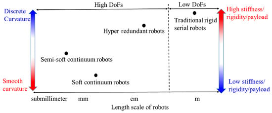
Figure 1.
The comparison between CCRs and rigid serial robots.
The main purposes of this paper are to provide an overview and prospects of CCRs. This paper covers a wide range of CCRs and details in the basic transmission units, drive systems, stiffness control, sensing system and four key challenges (including friction, buckling, singularity and twisting). Questions from learners/beginners in this field can be answered, like “How many types of CCRs are there?”, “What are the differences between different types of CCRs?” and “What are the characteristics and problems of CCRs?”.
In recent years, some papers reviewed the current advance of continuum robots. For example, Burgner-Kahrs et al. [25] summarised the medical continuum robots, including the design, modelling, control, actuation and sensing of continuum manipulators. They provided perspectives for the future by discussing current limitations and challenges. Runciman et al. [26] described the traits of soft robotic devices, including the materials, manufacturing methods, mechanical programming/embodied intelligence, actuation, stiffness variation and locomotion methods. They presented some prospects on the application, working principle, materials and manufacture, which can assist researchers in designing new robots. Kolachalama et al. [27] surveyed numerous bioinspired continuum robots that have been developed over two decades. They also provided detailed descriptions of bio-inspired design, mechanical design, construction material and force actuation.
Compared with the existing literature review on continuum robots, the main contributions in our paper include the following:
(1) We focus on a systematic survey of compliant continuum robots, which are not limited to specific applications, such as medical or manipulation purposes.
(2) Few literature review papers have summarised the characteristics of each type of CCR, including the merits and drawbacks. We emphasise the common problems and methods of avoiding them.
(3) Based on the above work, we present five prospects on CCRs, which are promising and different from other literature review papers.
This paper is organised as below. Section 2 describes the rules of the literature search and the trends of different CCRs, which are classified according to basic transmission units. In Section 3, the merits and drawbacks of CCRs formed with different basic transmission units and drive systems are detailed. Section 4 illustrates the variable stiffness and sensing systems for CCRs. The friction, buckling, singularity and twisting are discussed in Section 5. Future perspectives are drawn in Section 6.
2. Development of CCRs
In this section, we first describe the literature search method, which selected 180 relevant papers from the database. Then the development and classifications of the CCRs from 2000 to 2021 are discussed.
2.1. Literature Search
We surveyed the publications related to CCRs, and a large proportion of selected papers are from leading mechanisms and robotics journals, such as IEEE, ASME and SAGE. Table 1 shows the representative journals with those selected papers using several keywords. The rules of papers selected are also described.

Table 1.
Keywords and reviewed journals.
- Included papers
The CCR has a fixed end and a free end, which means worm-motion or snake-motion serial robots are not included.
The CCR should have elastic or compliant parts.
The paper can be obtained at the time of searching.
- Excluded papers
Patent papers and surveys are excluded.
Continuum robots without any compliant parts are excluded.
Parallel elastic robots are excluded.
2.2. Trends and Classifications of CCRs
The development of CCRs is shown in Figure 2 from 2000 to 2021. The prototype of CCR was introduced in 2000. It consists of elastic springs, rigid disks and rotational joints, and it is driven by cables [28]. During the following years, there was little research about CCRs from 2002 to 2013, but since 2014, there was a rapid increase in research of CCRs, as shown in Figure 2, and the cumulative results can also be seen.
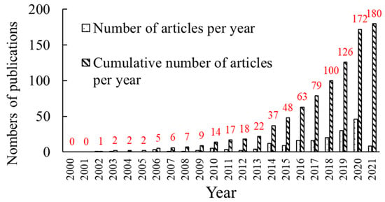
Figure 2.
The numbers of publications about CCRs per year.
CCRs are divided into eleven types according to basic transmission units, as shown in Figure 3. Soft-tube CCRs belong to soft CCRs, while others belong to semi-soft CCRs. Backbone, soft-tube, concentric-tube and spring CCRs account for a large proportion, followed by compliant-joint, bellow, origami and hybrid CCRs, and the rest of the types are analysed by researchers recently. Their characteristics and problems are summarised in Table 2, which are detailed in the following Sections.
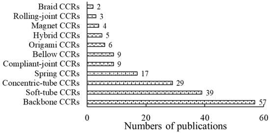
Figure 3.
The numbers of publications about different CCRs from the literature review.

Table 2.
Descriptions of CCRs.
3. Different Basic Transmission Units and Drive Systems
In this section, the basic transmission units and drive systems are described. The combination of different basic transmission units to form a CCR is called a hybrid CCR, which is also illustrated at the end of this section.
3.1. Basic Transmission Units
3.1.1. Backbone CCRs
The backbone CCRs are shown in Figure 4. Most backbones are made of Nickel-Titanium (NiTi) and polypropylene [7]. A centre backbone, secondary backbones (or cables) and several rigid disks are commonly used to form a backbone CCR, shown in Figure 4a [1,6,11,29,30,31,32,33,34,35,36,37,38,39,40,41,42,43,44,45]. The central backbone is connected to all the disks. The secondary backbones (or cables) are only connected to the end disk and freely slide in the disk holes for driving the CCR. A backbone CCR also can consist of multi-secondary backbones without a centre backbone, shown in Figure 4b [39], which is wearable and used for shoulder recovery. The centre backbone can be an elastic tube [44], an elastic notched tube [2], a half elastic notched tube [46], or an elastic V-shape tube [47,48], shown in Figure 4c. The last three tubes can be employed as backbone CCRs without rigid disks.
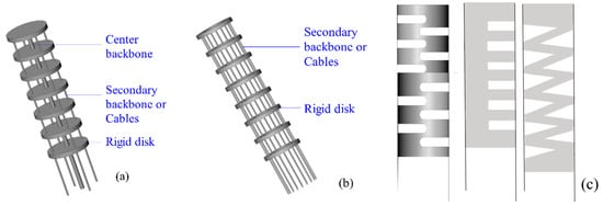
Figure 4.
Backbone CCRs: (a) A robot with a centre backbone [1,51,52,53], (b) a robot without a central backbone [39] and (c) notched backbones [48].
The metrics of the backbone are as follows. The distance between two disks can be evenly distributed. The continuous configuration of backbones benefits kinematics modelling. If the backbone has multi-segments, all the endpoints of different segments can be on the same curve, which is easy to correct the curve closing to desired one [31]. The rigidity of the backbone CCR can be adjusted by two methods, including increasing the number of secondary backbones [39] and inserting a rod moving in the centre backbone tube [12,46,49]. The effective bending section of the backbone CCR is controllable by regulating the inserting length of the rod. However, the torsional rigidity of the backbone CCRs is necessary to be enhanced to avoid a low payload and a small stiffness control range [50].
3.1.2. Soft-Tube CCRs
Soft-tube CCRs are the softest type among the CCRs, shown in Figure 5. The soft-tube CCR in Figure 5a [4,54] has a silicone tube, which is actuated by pneumatic, shape memory alloy and multi-embedded tendons. The soft-tube CCR in Figure 5b [55] has a silicone-backbone shape, consisting of a free chamber, six actuation chambers and three driving cables. Its stiffness can be regulated by the pneumatic pressure. The catheter has a sub-millimetre size, shown in Figure 5c, and it is usually made of urethane rubber [56] and polymer [57]. The stiffness of the soft-tube CCRs in Figure 5a,c is less rigid than that of Figure 5b. On the other hand, soft-tube CCRs can be actuated by driving cable, pneumatic champers, shape memory alloy, or electro-polymer. The first two drive systems have higher ratios of power to weight than others. A soft-tube CCR always requires a compliant actuator with a high ratio of power to weight than other CCRs, due to the hyper-redundant DOF [58], so cables and pneumatic champers are commonly used in soft-tube CCR.

Figure 5.
Soft-tube CCRs: (a) A silicone-tube CCR [4,54], (b) the cross section of another silicone-backbone CCR [55] and (c) a catheter CCR [56,57,62,63,64,65].
Soft-tube CCRs have a large elastic deformation and hyper-redundant DoFs. However, their higher compliance reduces the rigidity and positioning accuracy significantly [59]. The lack of rigidity of soft material can result in buckling and strong nonlinearities of the kinematic model. In 2018, Li et al. tried to avoid buckling by optimising controlling models [60]. Soft skin is easy to be torn and punctured, so Wang et al. combined different types of fibres into the silicone to improve their strength and durability [61].
3.1.3. Concentric-Tube CCRs
Concentric tubes are first introduced by Webster et al. [66]. Most tubes are made of superelastic Nitinol, and some of them are made of polyether block amide [67]. They are pre-curved and superelastic, as shown in Figure 6. The concentric tubes are inserted inside each other, and they are translated and rotated axially about the concentric axis at the base by tube interactions [68,69]. In this way, the length and curve of the concentric-tube CCR are varied.
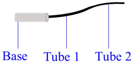
Figure 6.
A two-tube concentric-tube CCR [76,77].
The main advantage of concentric-tube CCRs is the sub-millimetre body with enough stiffness, such as a 0.8 mm-diameter tube [18], which leads to a lower infection possibility during the surgery. However, the kinematic analysis is difficult for the special actuation. If the stiffness of these tubes is not comparable, or elastic energy storage occurs in high tube curvatures, the rapid snapping problem may happen [18]. The snaping problem means the CCR snaps quickly from one configuration to another with the energy released suddenly [70]. The concentric-tube CCR should be snap-free to avoid serious harm to patients [71]. In addition, they have limited variations of resultant curvatures as the tubes are pre-curved, so the minimum requirement for the concentric-tube CCRs is to extend into the body smoothly [68,72,73]. The frictions between tubes should not be neglected [71,74,75].
3.1.4. Spring CCRs
Springs can be used in two ways to form a spring CCR, including inner helical springs and outer helical springs, as shown in Figure 7. An inner helical spring can be employed as a central backbone [78,79,80,81,82,83,84,85] to evenly distribute disks. An outer spring can be multi-disks to confine cables [86,87,88]. Most spring CCRs are made of steel or NiTi, and they are actuated by cables.
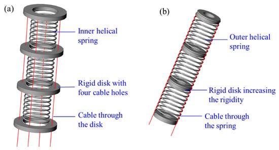
Figure 7.
Spring CCRs formed with: (a) An inner helical spring [79,89] and (b) an outer helical spring [85].
A helical spring has a linear relationship between force and displacement, i.e., an unchanged spring constant, which simplifies the kinematic analysis significantly [79]. The workspace of helical spring CCRs can be expanded by applying a high spring constant. The unwanted extension, uncontrolled compression and singularity can be avoided by applying a low spring constant. The combinations of high and low spring constants can improve torsional rigidity [79]. In addition, spring can also be a buffer to reduce the effects from the environment [17].
3.1.5. Compliant-Joint CCRs
Compliant joints are designed with elastic blades, wire beams, and rigid disks. Blades and wire beams are commonly made of NiTi [20] and polyethylene [90]. Most disks are made of acrylonitrile butadiene styrene (ABS) material for lightweight, and they can constrain cables [91] and increase the rigidity of CCRs [88]. The geometric difference between blade and wire beams is the ratio of width to thickness. The ratio of a blade is larger than 10, and that of a wire beam is equal to 1. Figure 8 shows the compliant joints, and they can be arranged in series to form a CCR. The compliant-joint CCRs are actuated by cables or backbones, and their curves are varied with the rotations and translations of the elastic blades or wire beams.
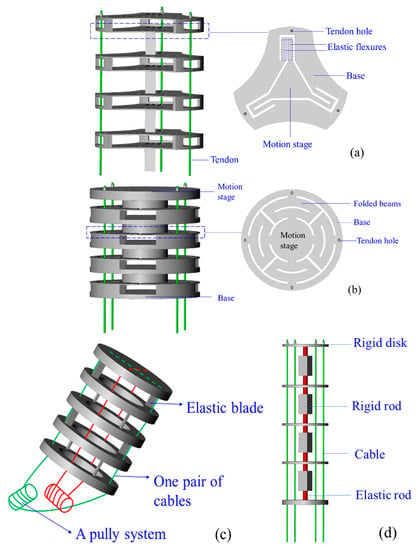
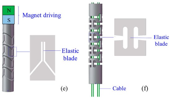
Figure 8.
Different compliant joints for the compliant-joint CCRs: (a) A planar spring [92], (b) a planar spring with minimised parasitic motions [93], (c) multi-two-pivots compliant joints [20], (d) a compliant joint with two short elastic beams [94], (e) multi compliant joints with elastic blades [95] and (f) multi compliant joints with round-corner blades [96].
Compared with the rotational symmetric planar spring of Qi et al. [92], shown in Figure 8a, the planar spring of Awtar et al. [93] is a mirror-symmetric consisting of eight folded beams, which decreases parasitic motions significantly, shown in Figure 8b. Dong et al. presented two types of compliant joint with elastic blades [20] and short beams [94], shown in Figure 8c,d, respectively. The compliant-joint CCR formed with the multi-elastic blades can anti twisting compared with the CCR formed with two short beams. Thomas et al. [95] and Zhang et al. [96] designed compliant-joint CCRs with elastic blades, shown in Figure 8e,f, respectively.
3.1.6. Bellow CCRs
Figure 9 shows a segment of a bellow CCR. Most bellow CCRs are made of polyamide, and they are actuated by pneumatic or hydraulic pressure with a cables-driven assistant. They can expand or elongate with variable curves as expected by pulling or pushing cables when bellows are filled with air.
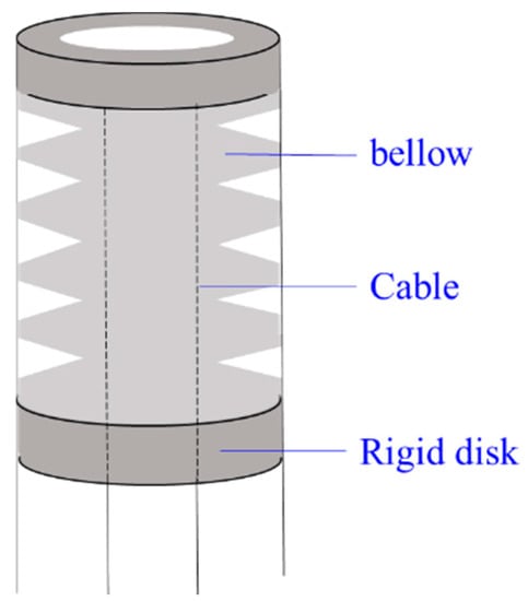
Figure 9.
A bellow CCR with cable-driven system [99].
Bellow CCRs are lightweight with a smooth curvature. Another advantage of the bellow is to be employed as an anti-buckling support structure if they are made of NiTi material [43], as NiTi is more rigid than polyamide with enough elasticity. However, bellow CCRs are sometimes unreliable for the non-stationarities during pneumatic or hydraulic actuation [97]. The rigidity of polyamide bellow CCRs is relatively low, so the disks are usually added around the bellow to increase the rigidity [98].
3.1.7. Origami CCRs
Mirror folds, water bomb, folds and reverse folds are basic folds for origami continuum robots. Origami CCRs are made of photopolymer resin or sticky polyamide film [100], which are driven by cables [101,102] as shown in Figure 10. Each crease of the origami can be regarded as a 360-degree revolute joint, so Origami CCR has two types of body shapes, including a 2D shape and a 3D shape. They can go through a constrained environment in a smaller 2D shape and morph into a 3D device. If they are applied in minimally invasive surgery, the possibility of infection decreases.
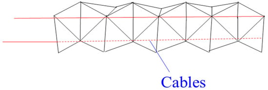
Figure 10.
An origami CCR with a cable-driven system [101,102].
3.1.8. Magnet CCRs
Magnetic CCRs are another type of sub-millimetre continuum robots, including permanent-magnet-joint CCRs [103] and magnetic-fluid CCRs [23]. Permanent magnets and magnetic fluids are controlled in the magnet field without any actuation wires. A permanent-magnet-joint CCR is shown in Figure 11. The elastic beams are actuated by the interactions of N and S poles. As for magnetic-fluid CCRs, the magnitude of the magnet field affects the viscosity of the magnetic fluid, and the viscosity can be close to the solid viscosity with the increase of the magnitude. Magnet CCRs can also be mounted on medical devices and serving as a guide.
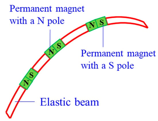
Figure 11.
A permanent-magnet CCR [103].
3.1.9. Rolling-Joint CCRs
Rolling-joint CCRs are special for a variable neutral line of the robot, as shown in Figure 12. Most rolling joints are made of ABS material to reduce weight. They are actuated by non-circular spur gears [104] as the asymmetric arrangement of rolling joints (∆x ≠ ∆y), and the nonlinear actuating relationship of force and tension is complex to model [105]. Compared with the friction between cables and disk holes, the friction between rolling joints should not be neglected.
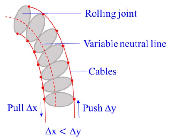
Figure 12.
A rolling-joint CCR with a cable-driven system [105].
3.1.10. Braid CCRs
Braid CCRs are inspired by human muscles, which are braided with non-extensible, but flexible fibres in helical arrays. They can extend, contract and bend by actuating embedded radial and longitudinal tendons [106], and they can also be actuated by the pneumatic artificial muscles [107]. They can vary stiffness by antagonistically actuating actuators or increasing the pneumatic pressure. The size of this robot is not miniature, ranging from 10 cm to 27 cm.
3.1.11. Hybrid CCRs
Hybrid CCRs are designed for complementing the shortcomings of a basic unit with the merits of another. Figure 13 shows the eight types of combinations of the different basic units. Most hybrid CCRs consist of a backbone due to the continuous shape.

Figure 13.
Combinations of different basic transmission units for the hybrid CCRs.
- Backbone-Concentric-Tube CCR
Concentric-tube CCRs can be submillimetre, but they have limited resultant curves and snapping problems. Backbone CCRs are flexible, but the coupling between different segments of a backbone CCR is still a challenge. Wu et al. [108] introduced a backbone-concentric-tube CCRs, whose dexterity is improved and the size is submillimetre. They analysed three combinations of the backbone-concentric-tube robot, as shown in Figure 14. The results show that design II can avoid snapping and coupling of different segments compared with others.
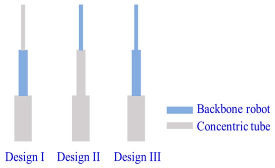
Figure 14.
Three designs of the backbone-concentric-tube CCRs [108].
- Backbone-Bellow CCR
The nickel bellow has much higher rigidity than a polyamide bellow. The torsional rigidity of the backbone CCRs is relatively low. Xu et al. introduced a backbone-bellow CCR, whose nickel bellows wrap outside of the backbones [43]. The torsional rigidity of the backbone CCR is enhanced more than four times when a nickel bellow is integrated, and the bending capabilities are not compromised.
- Notched Backbone-Spring CCR
Sharp bending is a challenge for concentric-tube CCRs. To maintain the miniature size and enable sharp bending, Francis et al. [86] introduced a new asymmetric notched backbone-spring CCR, where a helical spring wraps outside of a notched backbone tube, as shown in Figure 15. The helical spring is also used to confine the cables.
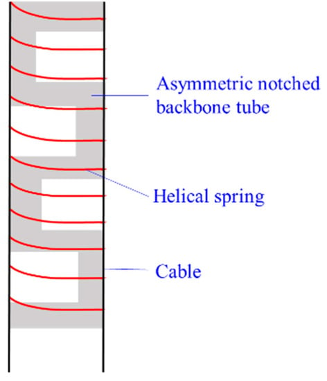
Figure 15.
The design of the notched backbone-spring CCRs [86].
- Soft tube-Spring CCR
Xing et al. [109] designed a soft tube-spring CCR, which is super flexible and driven by cables. The spring is employed for confining cables. It is different from the above hybrid CCRs as the spring is in the silicone tube, as shown in Figure 16.
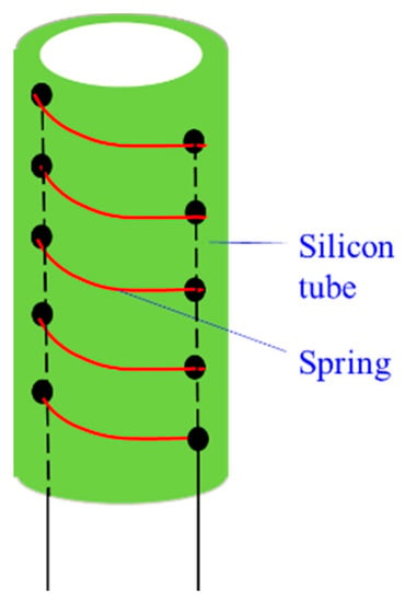
Figure 16.
The soft tube-spring CCR [109].
- Soft tube-Origami manipulator
Li et al. presented an origami gripper with soft silicone skin [110]. This gripper is actuated by pneumatic, which can catch different things without shape requirements. This is not a CCR, but it is promising to similarly design a silicone-origami CCR in the future.
3.2. Drive Systems
Drive systems depend on the basic transmission units of CCRs significantly. Most semi-soft CCRs can be actuated by backbones or cables. The main difference between the backbone-driven and the cable-driven system is as follows. The minimal number of backbones to bend a CCR in any direction is two, but that of cables is three. The reason is a backbone can be compressed and extended, while a cable cannot be compressed. The third actuating backbone or the fourth cable can be employed as the actuation redundancy [111]. A pully system usually actuates one pair of cables, which motivates Dong et al. to present a spooling system (i.e., twin pully systems) to minimise the size of the actuation system significantly [112]. In addition, cable tension is required to be calculated for avoiding cable slack [20], and the backbone-driven system does not have this problem.
Most soft CCRs are actuated by pneumatic and hydraulic pressure, which can modify the length of chambers by varying the air or fluid pressure in the chambers [98]. Cable-driven assistance is usually used for soft CCRs. Shape memory alloy (SMA) and electroactive polymer (EAP) are also used in CCRs. Shape memory alloy can change into a certain shape when the temperature reaches the critical temperature [82,113,114]. Electroactive polymer is a special material that contracts and extends by soft embedded compliant electrodes [115,116]. The advantages and disadvantages of different drive systems are summarised in Table 3.

Table 3.
Summary of different drive systems.
4. Stiffness and Sensing Systems
Stiffness and sensing systems of CCRs determine the motion range and motion accuracy. In this section, the methods of designing variable stiffness and sensing systems are illustrated.
4.1. Stiffness
The dexterity and payloads depend on the stiffness of a CCR. Buckling should be avoided, especially for the CCRs actuated by the compressive-force-based drive systems, like the cable-driven system, and backbone-driven system. Many researchers are motivated to increase the stiffness for a large stiffness-control range or a large payload. For example, adding rigid disks or NiTi bellows along the CCRs as discussed in Section 3.
On the other hand, variable stiffness enables CCRs to obtain the characteristics of both traditional rigid robots and compliant robots. They can deform their elastic bodies easily to go through the constraint environment, and exert enough payloads by stiffening the elastic bodies. Variable stiffness can be achieved in four ways, including applying dimension jamming [30,117], using special alloys (such as SMA [114] and low-melting-point alloy [109]), designing the mechanism of the CCR [49,79,105], actuating the CCR antagonistically [55,106,118]. Figure 17 shows different types of CCRs with variable stiffness.
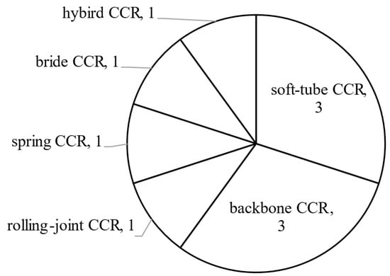
Figure 17.
Numbers of publications about variable stiffness in different CCRs.
4.1.1. Applying Dimension Jamming
The dimension jamming includes layer jamming and granules jamming. The granules (or layers) are arranged between the inner and outer soft tubes. Their working principle is ‘pressure-friction-stiffness’ [30]. The stiffness varies with the friction between the layers (or granules), i.e., the stiffness increases with the increase of frictions, and vice versa. The air pressure between the inner and outer soft tubes and the materials of the layers (or granules) are the main contributing factors to the friction. When the pressure closes to vacuum, the granules (or layers) are closed to each other tightly, and the stiffness increases significantly. The working principles of granule jamming and layer jamming are briefly shown in Figure 18. Clark et al. summarised a series of hybrid jamming methods to design the variable stiffness [117], such as rigid granules and layer jamming method, and deformable granules and layer jamming method.

Figure 18.
Working principles of the granule jamming and layer jamming: (a) A soft tube before vacuum, (b) a stiffening tube after vacuum with granules jamming and (c) a stiffening tube after vacuum with layer jamming.
4.1.2. Using Special Alloys
The special alloys include SMA and low-melting alloy. Yang et al. [114] designed a backbone CCR with SMA springs, which is actuated by three backbones. The phase-transition temperature of SMA springs is controlled by electrical currents. The SMA is employed to ‘unlock’ or ‘lock’ the movements of the rods between two disks by regulating electrical currents. Xing et al. [109] designed a hybrid CCR, including silicone tubes and tubular hollow springs. The silicone tube is filled with a low-melting-point alloy. The tubular hollow spring is used for transferring cold or hot water, and the temperature of the alloy can be regulated. The alloy is in a solid phase when the temperature is less than the melting point, and the stiffness of the CCR increases. Otherwise, it is in a fluid phase. The alloy can reversibly transfer between a fluid phase and a solid phase with a small change of volume.
4.1.3. Designing the Mechanism of the CCR
Zhao et al. [49] introduced a backbone CCR. The curvature-constraint rods are inserted into the backbone tubes, and the stiffness of the CCR varies with the inserted length of the rods. The secondary backbones can regulate the length of the curvature-constraint rods. Li et al. [79] presented a spring CCR and used different spring constants to vary stiffness along with the CCR. Kim et al. [105] designed an asymmetric rolling-joint CCR, whose neutral-line is variable. The stiffness of the CCR varies by regulating the cable tension. They verified the relation between the stiffness and the cable tension is close to linear, due to the variable neutral-line.
4.1.4. Actuating the CCR Antagonistically
This method is suitable for the CCR with a hybrid actuation, such as soft-tube CCRs and bellow CCRs. The stiffness of the CCRs varies by antagonistically actuating two types of actuation. Shiva et al. [55] and Stilli et al. [118] introduced soft-tube CCRs with pneumatic chambers and tendons. The stiffness of the CCRs is controlled by the inflatable-chamber pressure and the tendon extension. Hassan et al. [97] presented a braid CCR with tendons and radial actuators. The radial actuators are used for expending or contracting the braid CCR radially.
4.2. Sensing Systems
Sensing systems include extrinsic sensors and intrinsic sensing. Extrinsic sensors are mounted on the CCRs, including shape sensors [119], deflection sensors [109], force/torque sensors [75,83,86,114], electromagnetic sensors [120] and pressure sensors [61], etc. For example, tracking sensors can increase the accuracy of the orientation by directly measuring the tip position [121]. Soft sensors can be embedded on the CCRs with a silicone skin for shape and force estimation, like polyvinylidene fluoride (PVDF) deflection sensors [122] and helically wrapped fibre Bragg grating (FBG) sensors [75]. However, it is difficult to have a minimised size of the CCRs because of the wires and size of these sensors. In addition, some sensors are not accurate enough, due to environmental noises. For instance, electric/magnetic noises can influence the accuracy of electromagnetic sensors [123].
Xu et al. firstly introduced intrinsic sensing for backbone CCRs [1,124]. Intrinsic sensing is also called load sensing. The external wrench/forces can be solved in the virtual work model of the CCR with prior knowledge [1]. Bajo et al. [6] further derived a new force-sensing algorithm based on Xu et al., and the interactions with the environment are fully characterised. Yuan et al. derived an external force-sensing method based on the tip position and direction and the driving cable tension, which is also verified by a backbone CCR [45]. Haraguchi et al. presented a spring-backbone CCR, and external forces can be estimated from the dynamic model of the CCR [78]. Burgner et al. [125] applied the intrinsic force-sensing algorithm of Xu et al. [1] on a concentric tube CCR. Figure 19 shows the numbers of publications using extrinsic sensors and intrinsic sensing. Most researchers used extrinsic sensors to increase motion accuracy. It is still challenging to use intrinsic sensing, due to the mechanisms and drive systems of CCRs.
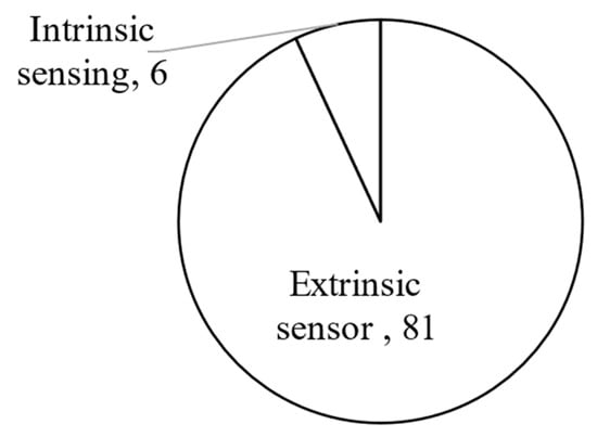
Figure 19.
The numbers of publications using extrinsic sensors and intrinsic sensing.
5. Problems of Different CCRs
A traditional rigid serial robot does not have twisting and buckling, but they are special problems of CCRs. In this section, friction, buckling, singularity and twisting are discussed. These problems can decrease the motion accuracy or even cause the failure of the CCRs. However, not all of them are required to be solved urgently, which depends on their applications and errors analysis. The numbers of publications considering them are shown in Figure 20. We found that friction and buckling account for large proportions, followed by singularity and twisting.
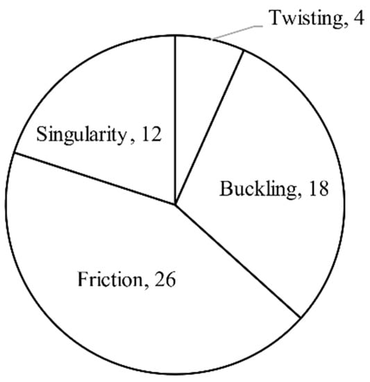
Figure 20.
Numbers of publications about friction, buckling, singularity and twisting.
5.1. Friction
Friction influences the position and direction of CCRs. Some researchers neglect friction by using nylon-coated [126], Teflon-coated cables [127] and lubrication [92]. Other researchers include friction in the analytical models of CCRs, and the medical surgery CCRs account for a large proportion. There are four types of frictions, including the friction between the cables and disk holes [2,10,42,78,83,128] or between cables and the catheter [65,121]; friction between backbones and actuation conduits [6,9,41,129] or between backbone and disks [11]; friction between concentric tubes [72,121,130]; and friction between rolling joints [104]. In addition, the concentric tube friction is a beginning, and most modelling of the concentric CCRs neglects the friction [67,69,71,72,131].
The friction coefficient and normal forces are the main contributing factors to the friction. The friction coefficient is used to be calculated by experiments [6,10,11] and a few by estimation [9]. The normal force is calculated by the equilibrium equations of actuation force, or cable tension, or experiment. Three friction models have been applied in the modelling of CCRs, including the Coulomb model [10,129,132], Capstan model and Dhal model.
5.1.1. Coulomb Friction Model
The Coulomb friction is also called sliding friction, as described in Equation (1) [11]. The static friction coefficient is assumed to be equal to the kinetic friction coefficient. This model is employed for analysing the tangential forces between contact surfaces [133], where tangential forces indicate the forces caused by sliding and rolling [134].
where Fcb denotes the resulting Coulomb friction; FN denotes the normal force on the contact surface; μ is the friction coefficient.
5.1.2. Capstan Friction Model
The Capstan friction model is also called the belt friction model, as described in Equation (2) [128] and Figure 21. The advantages of this model are estimating and updating the internal friction, including the friction between the cable and sheath when the shape of the sheath and the radius of the robot curvature change [9].
where, Fc denotes the resulting Capstan friction; F is the resulting holding force on the other side of the capstan; F0 is the applied tension on the rope; μ is the friction coefficient, α is the contact angle in radians [135].
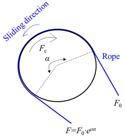
Figure 21.
The Capstan friction model [9].
5.1.3. Dahl Friction Model
The classical Dahl friction model relates to the cable sliding speed and the displacement of the friction force, as described as Equation (3) [136].
where FD denotes the resulting Dahl friction; x denotes the sliding displacement. Fs denotes steady-state friction; σ denotes the initial rate of the force to the displacement; α is commonly to be 1; v is the sliding velocity.
Jung et al. modified the Dahl friction model, whose Fs is not fixed and depends on the radius of curvature and the normal force between the tendon and lumen [136,137].
The above friction models are suitable for continuous-contact friction. Except for the Dahl friction model, the Coulomb friction model and Capstan friction model have no dependence on sliding speed. If the CCR has a typical discrete-interacted-cable actuation as described in [83], the discrete contacts influence the deflections of the CCR. Gao et al. [83] introduced a friction model, which is suitable for the discrete contacts. This model is derived with consideration of cable loading history and the effects of variable friction coefficients.
5.2. Buckling
From the review, there are four methods for avoiding buckling as follows.
5.2.1. Controlling the Parameter Related to Buckling in the Model
Li et al. [60] presented a soft-tube CCR with pneumatic actuation. They derived the air-pressure-change equation with a given path tracking, and the buckling is avoided by controlling the air pressure limited to a certain level. Gilbert et al. [71] analysed a concentric-tube CCR. They derived the configuration equation of the CCR, which relates to bending angle, material properties, the geometric of the tube and loads. The CCR avoids buckling by controlling the last three parameters of the equation.
5.2.2. Increasing Rigidity of the CCR
Xu et al. [138] presented a backbone CCR, and they avoid the backbone buckling by adding spacer rings. Frazelle et al. [88] designed a spring CCR with multi-disks to avoid the bucking of the spring. Haraguchi et al. [78] designed a backbone-spring CCR with a backbone-driven system, and the secondary backbones are wrapped in a rigid tube to avoid buckling.
5.2.3. Using Actuation Redundancy
Simaan et al. [91] designed a backbone CCR with a backbone-driven system. The fourth driving backbone is used for the actuation redundancy to avoid buckling. Yip et al. [7] and Amanov et al. [139] analysed backbone CCRs with a cable-driven system, and the pre-tensions along the cables are used to avoid buckling.
5.2.4. Keeping Applied Loads under the Critical Force
Gan et al. [140] presented a soft-tube CCR, and Thomas et al. [95] designed a compliant-joint CCR, and they avoid buckling by applying the loads below the critical load of the buckling.
5.3. Singularity
From the review, the singularity configuration of concentric-tube CCRs is special. That is, some pre-curved tubes reaching the same position when the inner and outer tubes rotate together. A common singularity configuration of other CCRs is the body of CCR is vertical with a zero-bending angle.
As for one segment of CCR’s singularity, we can use three methods to judge the singularity, including the Jacobian matrices, calculating condition number (the ratio of maximum singular value to minimal singular value), and using deflection sensors [122]. When the Jacobian matrix is ill-defined [1] or the condition number is infinite [123], the CCR has the singularity problem. These can be solved by mathematics, such as L’Hopital Rule [1,41,43], and Taylor series expansion [141]. As for a multi segments continuum robot, we should figure out the singularity of each segment with the above ways. If one segment of the CCR has the singularity, the CCR has the singularity.
5.4. Twisting
The twisting problem is not the rotation of the axial neutral axis. Here, the twisting is caused by the CCR’s self-weight and the payload, as shown in Figure 22 [20].
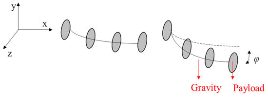
Figure 22.
The twisting of a CCR.
We can use the twisting angle (denoted by φ) to evaluate the twisting as expressed in Equation (4) [20].
where T is the twisting torch-applied on the robot, L is the length of the CCR, Iaxial is the moment of inertia along axial direction; G is the shear modulus of elasticity; E is Younth’s modulus; v is the Poisson’s ratio, and G = E/(2 + 2v). Noted that the expression of the twisting angle does not include actuation assistances [20].
φ = TL/GIaxial
Similar to the methods of avoiding singularity, twisting also can be prevented by increasing rigidity and using actuation redundancy. Dong et al. [20] introduced a compliant-joint CCR with twin-compliant pivots, and Yoshida et al. [46] inserted a super-elastic NiTi rod in the soft-tube CCR to increase the rigidity. They also reduced the twisting angle by increasing the cable tension [20]. Godage et al. [142] presented a new soft-tube CCR by evenly distributing constrainers (like a disk) along with the CCR, which strengthens the torsional stiffness significantly.
On the other hand, twisting can be neglected when the error caused by twisting is very small. For example, Xu et al. showed that the shape error caused by twisting is 1% of the total length (50 mm) [6], which means twisting has less effect on the shape. Twisting has less effect on the CCR configuration when the CCR has a short length and higher rigidity. If the length of the robot is longer, like more than 100 mm [13,46], or the CCR is soft, such as soft-tube CCRs [142], we should reduce the twisting of the CCRs.
6. Summary and Perspectives
From the review, a wide variety of compliant continuum robots (CCRs) have been repeated and analysed. Most CCRs are increasingly used in minimally invasive surgery. Only catheter CCRs and concentric-tube CCRs have a sub-millimetre size, and backbone CCRs have a millimetre size. Due to the small bodies, intrinsic sensing is applied in these robots rather than extrinsic sensors. As for drive systems, lightweight, small-size, efficient (less friction and backlash), high ratio of power to weight are needed. Drive systems with enough softness are also especially required for soft-tube CCRs. Five perspectives of the design of CCRs, collaborative CCRs, actuation redundancy and compensation, stress and obstacle avoidances are discussed as follows.
- Design of CCRs
To inspire the design of CCRs, we divide different CCRs into eleven categories based on basic transmission units and summarise the characteristics of each unit. It is also promising to design compliant-joint CCRs based on compliant mechanisms. They have great advantages over other CCRs for three reasons. First, most compliant-joint CCRs are driven with cables or backbones, and the body sizes can be minimised easily. Second, the compliance (i.e., DoF and DoC) of a compliant joint can be derived with the compliance of flexible blades or wire beams quickly. The commonly used way for calculating the compliance of a joint is the compliant-matrix method [143]. The ratio of DoF to DoC should be at least 100, and the parasitic motions can be neglected. Note that a parasitic motion indicates the unwanted motion along or about a constraint direction. Third, the compliance of the compliant joint is also applied for analysing parameters and providing design insights. For instance, Hao et al. [144] presented a class of planar compliant mechanisms with four-wire beams by regulating the tilt angle of each beam. In addition, we can also the freedom, actuation, and constraint topologies (‘FACT’) to design compliant mechanisms introduced by Hopkins et al. [145].
- Collaborative CCRs
A collaborative CCR system consists of multiple CCRs, working together in a parallel configuration, which can be used to drive a motion stage collectively. A collaborative CCR system incorporates the features of the parallel and continuum mechanisms. For example, Nuelle et al. [146] and Lilge et al. [147] designed new three-leg planar parallel CCRs, and each leg is actuated by a backbone CCR. The results show that the planar parallel CCRs have high dexterity and few singularities compared with the traditional parallel rigid robot. Ding et al. [148] presented a collaborative CCR system with two backbone CCRs and a camera module for single port access surgery. The two CCRs and the camera module can insert the abdomen through a single port. Then they deploy as a collaborative CCR system in the human body and work as surgical assistants.
- Actuation redundancy and compensation
Actuation redundancy has great advantages in reducing the effects of buckling and twisting as stated in Section 5.2 and Section 5.4, and increasing the stiffness, as shown in Section 4.1. Actuation can also be employed for compensating the discrepancy between the analytical model and actual motions. Especially for CCRs with the backbone-driven system [129], whose secondary backbones pass the channels in the actuation unit cone. The friction between the secondary backbones and channels is much larger than the friction between the secondary backbones and rigid disks. Xu et al. introduced an actuation compensation vector to compensate for the friction, assembly backlash and material uncertainties. In other words, the compensation vector includes the Coulomb friction equation and two scaling parameters of uncertainties, which are solved by using the recursive estimation [129].
- Stress consideration
Most semi-soft CCRs are made of superelastic metals, which belong to ductile materials. The maximum von Mises stress of the material should be less than its yield stress. Otherwise, inversible plastic deformation occurs on the CCR. We can calculate the maximum von Mises stress by using finite element analysis or empirical equations [149]. In addition, the stress concentration may occur on geometric irregularities of the material, especially for compliant-joint CCRs, and we can reduce the stress concentration by adding round corners for each elastic flexure.
- Obstacle avoidance
CCRs are quite suitable for avoiding obstacles and operating with their dexterous bodies in a constrained environment. As for hyper redundant rigid robots, the obstacle problem can be divided into four types, including static, dynamic, planar and spatial obstacles [150]. The obstacle avoidance of CCRs is at the beginning for researchers. Updating the Jacobian based on sensors’ feedbacks to avoid obstacles is usually used. For example, Yip et al. [7] updated the Jacobian by solving the tip constrained optimisation equations. Roesthuis et al. [151] regulated the Jacobian based on the feedbacks of fibre Bragg grating (FBG) sensors.
Author Contributions
Conceptualization, G.H. and S.L.; methodology, G.H.; software, S.L.; validation, G.H. and S.L.; formal analysis, G.H. and S.L.; investigation, S.L.; data curation, S.L.; writing—original draft preparation, S.L.; writing—review and editing, G.H.; supervision, G.H.; project administration, G.H.; funding acquisition, S.L.. All authors have read and agreed to the published version of the manuscript.
Funding
This research received no external funding.
Institutional Review Board Statement
Not applicable.
Informed Consent Statement
Not applicable.
Acknowledgments
Shiyao Li is funded by the China Scholarship Council.
Conflicts of Interest
The authors declare no conflict of interest.
References
- Xu, K.; Simaan, N. An Investigation of the Intrinsic Force Sensing Capabilities of Continuum Robots. IEEE Trans. Robot. 2008, 24, 576–587. [Google Scholar] [CrossRef]
- Moses, M.S.; Murphy, R.J.; Kutzer, M.D.M.; Armand, M. Modeling Cable and Guide Channel Interaction in a High-Strength Cable-Driven Continuum Manipulator. IEEE/ASME Trans. Mechatron. 2015, 20, 2876–2889. [Google Scholar] [CrossRef] [PubMed] [Green Version]
- Wang, L.; Simaan, N. Geometric Calibration of Continuum Robots: Joint Space and Equilibrium Shape Deviations. IEEE Trans. Robot. 2019, 35, 387–402. [Google Scholar] [CrossRef]
- Zheng, T.; Branson, D.T.; Guglielmino, E.; Kang, R.; Cerda, G.A.M.; Cianchetti, M.; Follador, M.; Godage, I.S.; Caldwell, D.G. Model Validation of an Octopus Inspired Continuum Robotic Arm for Use in Underwater Environments. J. Mech. Robot. 2013, 5, 021004. [Google Scholar] [CrossRef]
- Marchese, A.D.; Katzschmann, R.; Rus, D.L. A Recipe for Soft Fluidic Elastomer Robots. Soft Robot. 2015, 2, 7–25. [Google Scholar] [CrossRef] [Green Version]
- Bajo, A.; Simaan, N. Hybrid motion/force control of multi-backbone continuum robots. Int. J. Robot. Res. 2015, 35, 422–434. [Google Scholar] [CrossRef]
- Yip, M.C.; Camarillo, D.B. Model-Less Hybrid Position/Force Control: A Minimalist Approach for Continuum Manipulators in Unknown, Constrained Environments. IEEE Robot. Autom. Lett. 2016, 1, 844–851. [Google Scholar] [CrossRef]
- Alambeigi, F.; Bakhtiarinejad, M.; Sefati, S.; Hegeman, R.; Iordachita, I.; Khanuja, H.; Armand, M. On the Use of a Continuum Manipulator and a Bendable Medical Screw for Minimally Invasive Interventions in Orthopedic Surgery. IEEE Trans. Med. Robot. Bionics 2019, 1, 14–21. [Google Scholar] [CrossRef]
- Roy, R.; Wang, L.; Simaan, N. Modeling and Estimation of Friction, Extension, and Coupling Effects in Multisegment Continuum Robots. IEEE/ASME Trans. Mechatron. 2016, 22, 909–920. [Google Scholar] [CrossRef]
- Gao, A.; Murphy, R.J.; Liu, H.; Iordachita, I.I.; Armand, M. Mechanical Model of Dexterous Continuum Manipulators With Compliant Joints and Tendon/External Force Interactions. IEEE/ASME Trans. Mechatron. 2017, 22, 465–475. [Google Scholar] [CrossRef]
- Kato, T.; Okumura, I.; Song, S.-E.; Golby, A.J.; Hata, N. Tendon-Driven Continuum Robot for Endoscopic Surgery: Preclinical Development and Validation of a Tension Propagation Model. IEEE/ASME Trans. Mechatron. 2015, 20, 2252–2263. [Google Scholar] [CrossRef] [Green Version]
- Zhang, X.; Li, W.; Chiu, P.W.-Y.; Li, Z. A Novel Flexible Robotic Endoscope With Constrained Tendon-Driven Continuum Mechanism. IEEE Robot. Autom. Lett. 2020, 5, 1366–1372. [Google Scholar] [CrossRef]
- Dong, X.; Axinte, D.; Palmer, D.; Cobos, S.; Raffles, M.; Rabani, A.; Kell, J. Development of a slender continuum robotic system for on-wing inspection/repair of gas turbine engines. Robot. Comput. Manuf. 2017, 44, 218–229. [Google Scholar] [CrossRef] [Green Version]
- Hannan, M.W.; Walker, I.D. Analysis and experiments with an elephant’s trunk robot. Adv. Robot. 2001, 15, 847–858. [Google Scholar] [CrossRef]
- Zheng, T.; Branson, D.T.; Kang, R.; Cianchetti, M.; Guglielmino, E.; Follador, M.; Medrano-Cerda, G.A.; Godage, I.S.; Caldwell, D.G. Dynamic continuum arm model for use with underwater robotic manipulators inspired by octopus vulgaris. In Proceedings of the 2012 IEEE International Conference on Robotics and Automation, Saint Paul, MN, USA, 14–18 May 2012; Institute of Electrical and Electronics Engineers (IEEE): Piscataway, NJ, USA, 2012; pp. 5289–5294. [Google Scholar]
- Porter, M.M.; Adriaens, D.; Hatton, R.L.; Meyers, M.A.; McKittrick, J. Why the seahorse tail is square. Science 2015, 349. [Google Scholar] [CrossRef] [PubMed] [Green Version]
- Li, L.; Jin, T.; Tian, Y.; Yang, F.; Xi, F. Design and Analysis of a Square-Shaped Continuum Robot With Better Grasping Ability. IEEE Access 2019, 7, 57151–57162. [Google Scholar] [CrossRef]
- Webster, I.R.J.; Romano, J.M.; Cowan, N.J. Mechanics of Precurved-Tube Continuum Robots. IEEE Trans. Robot. 2009, 25, 67–78. [Google Scholar] [CrossRef]
- Mehling, J.S.; Diftler, M.A.; Chu, M.; Valvo, M.C. A Minimally Invasive Tendril Robot for In-Space Inspection. In Proceedings of the First IEEE/RAS-EMBS International Conference on Biomedical Robotics and BioMechatron, 2006. BioRob 2006, Pisa, Italy, 20–22 February 2006. [Google Scholar] [CrossRef]
- Dong, X.; Raffles, M.; Cobos-Guzmán, S.; Axinte, D.; Kell, J. A Novel Continuum Robot Using Twin-Pivot Compliant Joints: Design, Modeling, and Validation. J. Mech. Robot. 2015, 8, 021010. [Google Scholar] [CrossRef]
- Xu, W.; Liu, T.; Li, Y. Kinematics, Dynamics, and Control of a Cable-Driven Hyper-Redundant Manipulator. IEEE/ASME Trans. Mech. 2018, 23, 1693–1704. [Google Scholar] [CrossRef]
- Xu, W.; Meng, D.; Liu, H.; Wang, X.; Liang, B. Singularity-Free Trajectory Planning of Free-Floating Multiarm Space Robots for Keeping the Base Inertially Stabilized. IEEE Trans. Syst. Man Cybern. Syst. 2017, 49, 2464–2477. [Google Scholar] [CrossRef]
- Kim, Y.; Parada, G.A.; Liu, S.; Zhao, X. Ferromagnetic soft continuum robots. Sci. Robot. 2019, 4, eaax7329. [Google Scholar] [CrossRef]
- Majidi, C. Soft Robotics: A Perspective—Current Trends and Prospects for the Future. Soft Robot. 2014, 1, 5–11. [Google Scholar] [CrossRef]
- Burgner-Kahrs, J.; Rucker, D.C.; Choset, H. Continuum Robots for Medical Applications: A Survey. IEEE Trans. Robot. 2015, 31, 1261–1280. [Google Scholar] [CrossRef]
- Runciman, M.; Darzi, A.; Mylonas, G.P. Soft Robotics in Minimally Invasive Surgery. Soft Robot. 2019, 6, 423–443. [Google Scholar] [CrossRef] [Green Version]
- Kolachalama, S.; Lakshmanan, S. Continuum Robots for Manipulation Applications: A Survey. J. Robot. 2020, 2020, 1–19. [Google Scholar] [CrossRef]
- Hannan, M.W.; Walker, I.D. Kinematics and the Implementation of an Elephant’s Trunk Manipulator and Other Continuum Style Robots. J. Robot. Syst. 2003, 20, 45–63. [Google Scholar] [CrossRef]
- Shen, W.; Yang, G.; Zheng, T.; Wang, Y.; Yang, K.; Fang, Z. An Accuracy Enhancement Method for a Cable-Driven Continuum Robot With a Flexible Backbone. IEEE Access 2020, 8, 37474–37481. [Google Scholar] [CrossRef]
- Langer, M.; Amanov, E.; Burgner-Kahrs, J. Stiffening Sheaths for Continuum Robots. Soft Robot. 2018, 5, 291–303. [Google Scholar] [CrossRef]
- Ouyang, B.; Liu, Y.; Tam, H.Y.; Sun, N. Design of an Interactive Control System for a Multisection Continuum Robot. IEEE/ASME Trans. Mechatron. 2018, 23, 2379–2389. [Google Scholar] [CrossRef]
- Case, J.C.; White, E.L.; SunSpiral, V.; Kramer-Bottiglio, R. Reducing Actuator Requirements in Continuum Robots Through Optimized Cable Routing. Soft Robot. 2018, 5, 109–118. [Google Scholar] [CrossRef] [PubMed]
- Oliver-Butler, K.; Till, J.; Rucker, C. Continuum Robot Stiffness Under External Loads and Prescribed Tendon Displacements. IEEE Trans. Robot. 2019, 35, 403–419. [Google Scholar] [CrossRef]
- Ma, X.; Song, C.; Chiu, W.Y.P.; Li, Z. Autonomous Flexible Endoscope for Minimally Invasive Surgery With Enhanced Safety. IEEE Robot. Autom. Lett. 2019, 4, 2607–2613. [Google Scholar] [CrossRef]
- Gravagne, I.A.; Rahn, C.D.; Walker, I.D.; Member, S. Large Deflection Dynamics and Control for Planar Continuum Robots. IEEE/ASME Trans. Mechatron. 2003, 8, 299–307. [Google Scholar] [CrossRef] [Green Version]
- Rucker, D.C.; Webster, R.J. Statics and dynamics of continuum robots with general tendon routing and external loading. IEEE Trans. Robot. 2011, 27, 1033–1044. [Google Scholar] [CrossRef]
- Gravagne, I.A.; Walker, I.D. Manipulability, force, and compliance analysis for planar continuum manipulators. IEEE Trans. Robot. Autom. 2002, 18, 263–273. [Google Scholar] [CrossRef] [Green Version]
- Chikhaoui, M.T.; Lilge, S.; Kleinschmidt, S.; Burgner-Kahrs, J. Comparison of Modeling Approaches for a Tendon Actuated Continuum Robot With Three Extensible Segments. IEEE Robot. Autom. Lett. 2019, 4, 989–996. [Google Scholar] [CrossRef]
- Xu, K.; Zhao, J.; Qiu, D.; Wang, Y. A Pilot Study of a Continuum Shoulder Exoskeleton for Anatomy Adaptive Assistances. J. Mech. Robot. 2014, 6, 041011. [Google Scholar] [CrossRef]
- Rone, W.S.; Ben-Tzvi, P. Mechanics Modeling of Multisegment Rod-Driven Continuum Robots. J. Mech. Robot. 2014, 6, 041006. [Google Scholar] [CrossRef] [Green Version]
- Goldman, R.E.; Bajo, A.; Simaan, N. Compliant Motion Control for Multisegment Continuum Robots With Actuation Force Sensing. IEEE Trans. Robot. 2014, 30, 890–902. [Google Scholar] [CrossRef]
- Rone, W.S.; Ben-Tzvi, P. Continuum Robot Dynamics Utilizing the Principle of Virtual Power. IEEE Trans. Robot. 2014, 30, 275–287. [Google Scholar] [CrossRef]
- Xu, K.; Zhao, J.; Fu, M. Development of the SJTU Unfoldable Robotic System (SURS) for Single Port Laparoscopy. IEEE/ASME Trans. Mechatron. 2014, 20, 2133–2145. [Google Scholar] [CrossRef]
- Li, Z.; Zin Oo, M.; Nalam, V.; Duc Thang, V.; Ren, H.; Kofidis, T.; Yu, H. Design of a novel flexible endoscope-cardioscope. J. Mech. Robot. 2016, 8, 1–9. [Google Scholar] [CrossRef] [Green Version]
- Yuan, H.; Chiu, P.W.Y.; Li, Z. Shape-Reconstruction-Based Force Sensing Method for Continuum Surgical Robots With Large Deformation. IEEE Robot. Autom. Lett. 2017, 2, 1972–1979. [Google Scholar] [CrossRef]
- Yoshida, S.; Kanno, T.; Kawashima, K. Surgical Robot With Variable Remote Center of Motion Mechanism Using Flexible Structure. J. Mech. Robot. 2018, 10, 031011. [Google Scholar] [CrossRef]
- Du, Z.; Yang, W.; Dong, W. Kinematics Modeling of a Notched Continuum Manipulator. J. Mech. Robot. 2015, 7, 041017. [Google Scholar] [CrossRef]
- Kutzer, M.D.; Segreti, S.M.; Brown, C.Y.; Armand, M.; Taylor, R.H.; Mears, S.C. Design of a new cable-driven manipulator with a large open lumen: Preliminary applications in the minimally-invasive removal of osteolysis. In Proceedings of the 2011 IEEE International Conference on Robotics and Automation, Shanghai, China, 9–13 May 2011. [Google Scholar] [CrossRef]
- Zhao, B.; Zeng, L.; Wu, Z.; Xu, K. A continuum manipulator for continuously variable stiffness and its stiffness control formulation. Mech. Mach. Theory 2020, 149, 103746. [Google Scholar] [CrossRef]
- Xu, K.; Fu, M.; Zhao, J. An experimental kinestatic comparison between continuum manipulators with structural variations. In Proceedings of the 2014 IEEE International Conference on Robotics and Automation (ICRA), Hong Kong, China, 31 May–7 June 2014; Institute of Electrical and Electronics Engineers (IEEE): Piscataway, NJ, USA, 2014; pp. 3258–3264. [Google Scholar]
- He, B.; Wang, Z.; Li, Q.; Xie, H.; Shen, R. An Analytic Method for the Kinematics and Dynamics of a Multiple-Backbone Continuum Robot. Int. J. Adv. Robot. Syst. 2013, 10, 84. [Google Scholar] [CrossRef]
- Guo, H.; Ju, F.; Cao, Y.; Qi, F.; Bai, D.; Wang, Y.; Chen, B. Continuum robot shape estimation using permanent magnets and magnetic sensors. Sens. Actuators A Phys. 2019, 285, 519–530. [Google Scholar] [CrossRef]
- Ouyang, B.; Liu, Y.; Sun, D. Design of a three-segment continuum robot for minimally invasive surgery. Robot. Biomim. 2016, 3, 43. [Google Scholar] [CrossRef] [Green Version]
- Renda, F.; Giorelli, M.; Calisti, M.; Cianchetti, M.; Laschi, C. Dynamic Model of a Multibending Soft Robot Arm Driven by Cables. IEEE Trans. Robot. 2014, 30, 1109–1122. [Google Scholar] [CrossRef]
- Shiva, A.; Stilli, A.; Noh, Y.; Faragasso, A.; De Falco, I.; Gerboni, G.; Cianchetti, M.; Menciassi, A.; Althoefer, K.; Wurdemann, H.A. Tendon-Based Stiffening for a Pneumatically Actuated Soft Manipulator. IEEE Robot. Autom. Lett. 2016, 1, 632–637. [Google Scholar] [CrossRef] [Green Version]
- Dalvand, M.M.; Nahavandi, S.; Howe, R.D. An Analytical Loading Model for n-Tendon Continuum Robots. IEEE Trans. Robot. 2018, 34, 1215–1225. [Google Scholar] [CrossRef]
- Zhang, Z.; Dequidt, J.; Back, J.; Liu, H.; Duriez, C. Motion Control of Cable-Driven Continuum Catheter Robot Through Contacts. IEEE Robot. Autom. Lett. 2019, 4, 1852–1859. [Google Scholar] [CrossRef]
- Kang, R.; Guglielmino, E.; Zullo, L.; Branson, D.T.; Godage, I.; Caldwell, D.G. Embodiment design of soft continuum robots. Adv. Mech. Eng. 2016, 8, 1–13. [Google Scholar] [CrossRef] [Green Version]
- Kang, R.; Guo, Y.; Chen, L.; Branson, D.T.; Dai, J.S. Design of a Pneumatic Muscle Based Continuum Robot With Embedded Tendons. IEEE/ASME Trans. Mech. 2016, 22, 751–761. [Google Scholar] [CrossRef] [Green Version]
- Li, M.; Kang, R.; Branson, D.T.; Dai, J.S. Model-Free Control for Continuum Robots Based on an Adaptive Kalman Filter. IEEE/ASME Trans. Mechatron. 2017, 23, 286–297. [Google Scholar] [CrossRef]
- Wang, Y.; Gregory, C.; Minor, M.A. Improving Mechanical Properties of Molded Silicone Rubber for Soft Robotics Through Fabric Compositing. Soft Robot. 2018, 5, 272–290. [Google Scholar] [CrossRef]
- Camarillo, D.B.; Milne, C.F.; Carlson, C.R.; Zinn, M.R.; Salisbury, J.K. Mechanics Modeling of Tendon-Driven Continuum Manipulators. IEEE Trans. Robot. 2008, 24, 1262–1273. [Google Scholar] [CrossRef]
- Hasanzadeh, S.; Janabi-Sharifi, F. An Efficient Static Analysis of Continuum Robots. J. Mech. Robot. 2014, 6, 031011. [Google Scholar] [CrossRef]
- Lotfavar, A.; Hasanzadeh, S.; Janabi-Sharifi, F. Cooperative Continuum Robots: Concept, Modeling, and Workspace Analysis. IEEE Robot. Autom. Lett. 2017, 3, 426–433. [Google Scholar] [CrossRef]
- Yu, B.; Fernández, J.D.G.; Tan, T. Probabilistic Kinematic Model of a Robotic Catheter for 3D Position Control. Soft Robot. 2019, 6, 184–194. [Google Scholar] [CrossRef] [PubMed]
- Webster, R.J.; Okamura, A.M.; Cowan, N.J. Toward Active Cannulas: Miniature Snake-Like Surgical Robots. In Proceedings of the 2006 IEEE/RSJ International Conference on Intelligent Robots and Systems, Beijing, China, 9–15 October 2006; pp. 2857–2863. [Google Scholar] [CrossRef]
- Morimoto, T.K.; Okamura, A.M. Design of 3-D Printed Concentric Tube Robots. IEEE Trans. Robot. 2016, 32, 1419–1430. [Google Scholar] [CrossRef] [PubMed]
- Bergeles, C.; Gosline, A.H.; Vasilyev, N.V.; Codd, P.J.; Del Nido, P.J.; Dupont, P.E. Concentric Tube Robot Design and Optimization Based on Task and Anatomical Constraints. IEEE Trans. Robot. 2015, 31, 67–84. [Google Scholar] [CrossRef] [Green Version]
- Dupont, P.E.; Lock, J.; Itkowitz, B.; Butler, E.J. Design and Control of Concentric-Tube Robots. IEEE Trans. Robot. 2010, 26, 209–225. [Google Scholar] [CrossRef] [PubMed] [Green Version]
- Hendrick, R.J.; Gilbert, H.B.; Webster, R.J. Designing snap-free concentric tube robots: A local bifurcation approach. In Proceedings of the 2015 IEEE International Conference on Robotics and Automation (ICRA), Seattle, WA, USA, 25–30 May 2015; pp. 2256–2263. [Google Scholar] [CrossRef]
- Gilbert, H.B.; Hendrick, R.J.; Iii, R.J.W. Elastic Stability of Concentric Tube Robots: A Stability Measure and Design Test. IEEE Trans. Robot. 2016, 32, 20–35. [Google Scholar] [CrossRef] [Green Version]
- Rucker, D.C.; Webster, I.R.J.; Chirikjian, G.S.; Cowan, N.J. Equilibrium Conformations of Concentric-tube Continuum Robots. Int. J. Robot. Res. 2010, 29, 1263–1280. [Google Scholar] [CrossRef] [Green Version]
- Kudryavtsev, A.V.; Chikhaoui, M.T.; Liadov, A.; Rougeot, P.; Spindler, F.; Rabenorosoa, K.; Burgner-Kahrs, J.; Tamadazte, B.; Andreff, N. Eye-in-Hand Visual Servoing of Concentric Tube Robots. IEEE Robot. Autom. Lett. 2018, 3, 2315–2321. [Google Scholar] [CrossRef] [Green Version]
- Vandini, A.; Bergeles, C.; Glocker, B.; Giataganas, P.; Yang, G.-Z. Unified Tracking and Shape Estimation for Concentric Tube Robots. IEEE Trans. Robot. 2017, 33, 901–915. [Google Scholar] [CrossRef]
- Xu, R.; Yurkewich, A.; Patel, R.V. Curvature, Torsion, and Force Sensing in Continuum Robots Using Helically Wrapped FBG Sensors. IEEE Robot. Autom. Lett. 2016, 1, 1052–1059. [Google Scholar] [CrossRef]
- Iyengar, K.; Dwyer, G.; Stoyanov, D. Investigating exploration for deep reinforcement learning of concentric tube robot control. Int. J. Comput. Assist. Radiol. Surg. 2020, 15, 1157–1165. [Google Scholar] [CrossRef]
- Su, H.; Li, G.; Rucker, D.C.; Iii, R.J.W.; Fischer, G.S. A Concentric Tube Continuum Robot with Piezoelectric Actuation for MRI-Guided Closed-Loop Targeting. Ann. Biomed. Eng. 2016, 44, 2863–2873. [Google Scholar] [CrossRef]
- Haraguchi, D.; Kanno, T.; Tadano, K.; Kawashima, K. A Pneumatically Driven Surgical Manipulator With a Flexible Distal Joint Capable of Force Sensing. IEEE/ASME Trans. Mechatron. 2015, 20, 2950–2961. [Google Scholar] [CrossRef]
- Li, M.; Kang, R.; Geng, S.; Guglielmino, E. Design and control of a tendon-driven continuum robot. Trans. Inst. Meas. Control. 2018, 40, 3263–3272. [Google Scholar] [CrossRef]
- Yoon, H.-S.; Jeong, J.H.; Yi, B.-J. Image-Guided Dual Master–Slave Robotic System for Maxillary Sinus Surgery. IEEE Trans. Robot. 2018, 34, 1098–1111. [Google Scholar] [CrossRef]
- Santiago, J.L.C.; Godage, I.S.; Gonthina, P.; Walker, I.D. Soft Robots and Kangaroo Tails: Modulating Compliance in Continuum Structures Through Mechanical Layer Jamming. Soft Robot. 2016, 3, 54–63. [Google Scholar] [CrossRef]
- Kim, Y.; Cheng, S.S.; Diakite, M.; Gullapalli, R.P.; Simard, J.M.; Desai, J.P. Toward the Development of a Flexible Mesoscale MRI-Compatible Neurosurgical Continuum Robot. IEEE Trans. Robot. 2017, 33, 1386–1397. [Google Scholar] [CrossRef] [PubMed]
- Gao, A.; Zou, Y.; Wang, Z.; Liu, H. A General Friction Model of Discrete Interactions for Tendon Actuated Dexterous Manipulators. J. Mech. Robot. 2017, 9, 041019. [Google Scholar] [CrossRef]
- Frazelle, C.G.; Kapadia, A.D.; Walker, I.D. A Haptic Continuum Interface for the Teleoperation of Extensible Continuum Manipulators. IEEE Robot. Autom. Lett. 2020, 5, 1875–1882. [Google Scholar] [CrossRef]
- Feng, F.; Hong, W.; Xie, L. Design of 3D-Printed Flexible Joints With Presettable Stiffness for Surgical Robots. IEEE Access 2020, 8, 79573–79585. [Google Scholar] [CrossRef]
- Francis, P.; Eastwood, K.W.; Bodani, V.; Price, K.; Upadhyaya, K.; Podolsky, D.; Azimian, H.; Looi, T.; Drake, J. Miniaturized Instruments for the da Vinci Research Kit: Design and Implementation of Custom Continuum Tools. IEEE Robot. Autom. Mag. 2017, 24, 24–33. [Google Scholar] [CrossRef]
- Thuruthel, T.G.; Falotico, E.; Manti, M.; Pratesi, A.; Cianchetti, M.; Laschi, C. Learning Closed Loop Kinematic Controllers for Continuum Manipulators in Unstructured Environments. Soft Robot. 2017, 4, 285–296. [Google Scholar] [CrossRef] [PubMed]
- Frazelle, C.G.; Kapadia, A.; Walker, I. Developing a Kinematically Similar Master Device for Extensible Continuum Robot Manipulators. ASME J. Mech. Robot. 2018, 10, 025005. [Google Scholar] [CrossRef] [Green Version]
- Yeshmukhametov, A.; Buribayev, Z.; Amirgaliyev, Y.; Ramakrishnan, R.R. Modeling and Validation of New Continuum Robot Backbone Design With Variable Stiffness Inspired from Elephant Trunk. IOP Conf. Series Mater. Sci. Eng. 2018, 417, 012010. [Google Scholar] [CrossRef]
- Hao, G.; Dai, F.; He, X.; Liu, Y. Design and analytical analysis of a large-range tri-symmetrical 2R1T compliant mechanism. Microsyst. Technol. 2017, 23, 4359–4366. [Google Scholar] [CrossRef]
- Simaan, N.; Taylor, R.; Flint, P. A dexterous system for laryngeal surgery. In Proceedings of the IEEE International Conference on Robotics and Automation, 2004. ICRA ’04. 2004, New Orleans, LA, USA, 26 April–1 May 2004. [Google Scholar] [CrossRef]
- Qi, P.; Qiu, C.; Liu, H.; Dai, J.S.; Seneviratne, L.; Althoefer, K.A. A Novel Continuum Manipulator Design Using Serially Connected Double-Layer Planar Springs. IEEE/ASME Trans. Mechatron. 2015, 21, 1281–1292. [Google Scholar] [CrossRef] [Green Version]
- Awtar, S.; Slocum, A.H. Flexure systems based on a symmetric diaphragm flexure. In Proceedings of the ASPE 2005 Annual Meeting, Chicago, IL, USA, 10–14 September 2005. [Google Scholar]
- Dong, X.; Raffles, M.; Guzman, S.C.; Axinte, D.; Kell, J. Design and analysis of a family of snake arm robots connected by compliant joints. Mech. Mach. Theory 2014, 77, 73–91. [Google Scholar] [CrossRef]
- Thomas, T.L.; Venkiteswaran, V.K.; Ananthasuresh, G.K.; Misra, S. A Monolithic Compliant Continuum Manipulator: A Proof-of-Concept Study. J. Mech. Robot. 2020, 12, 1–11. [Google Scholar] [CrossRef]
- Zhang, T.; Ping, Z.; Zuo, S. Miniature Continuum Manipulator with 3-DOF Force Sensing for Retinal Microsurgery. J. Mech. Robot. 2021, 1–34. [Google Scholar] [CrossRef]
- Rolf, M.; Steil, J.J. Efficient Exploratory Learning of Inverse Kinematics on a Bionic Elephant Trunk. IEEE Trans. Neural Netw. Learn. Syst. 2014, 25, 1147–1160. [Google Scholar] [CrossRef]
- Bailly, Y.; Amirat, Y.; Fried, G. Modeling and Control of a Continuum Style Microrobot for Endovascular Surgery. IEEE Trans. Robot. 2011, 27, 1024–1030. [Google Scholar] [CrossRef]
- Walker, I.D. Continuous Backbone ‘Continuum’ Robot Manipulators. ISRN Robot. 2013, 2013, 1–19. [Google Scholar] [CrossRef] [Green Version]
- Kim, S.-J.; Lee, D.-Y.; Jung, G.-P.; Cho, K.-J. An origami-inspired, self-locking robotic arm that can be folded flat. Sci. Robot. 2018, 3, eaar2915. [Google Scholar] [CrossRef] [Green Version]
- Edmondson, B.J.; Bowen, L.A.; Grames, C.L.; Magleby, S.P.; Howell, L.L.; Bateman, T.C. Oriceps: Origami-Inspired Forceps. In Proceedings of the ASME 2013 Conference on Smart Materials, Adaptive Structures and Intelligent Systems. Volume 1: Development and Characterization of Multifunctional Materials; Modeling, Simulation and Control of Adaptive Systems; Integrated System Design and Implementation, Snowbird, UT, USA, 16–18 September 2013. [Google Scholar] [CrossRef]
- Zhang, K.; Qiu, C.; Dai, J.S. An Extensible Continuum Robot With Integrated Origami Parallel Modules. J. Mech. Robot. 2016, 8, 031010. [Google Scholar] [CrossRef]
- Edelmann, J.; Petruska, A.J.; Nelson, B.J. Magnetic control of continuum devices. Int. J. Robot. Res. 2017, 36, 68–85. [Google Scholar] [CrossRef]
- Suh, J.-W.; Kim, K.-Y.; Jeong, J.-W.; Lee, J.-J. Design Considerations for a Hyper-Redundant Pulleyless Rolling Joint With Elastic Fixtures. IEEE/ASME Trans. Mechatron. 2015, 20, 2841–2852. [Google Scholar] [CrossRef]
- Kim, Y.-J.; Cheng, S.; Kim, S.; Iagnemma, K. A Stiffness-Adjustable Hyperredundant Manipulator Using a Variable Neutral-Line Mechanism for Minimally Invasive Surgery. IEEE Trans. Robot. 2014, 30, 382–395. [Google Scholar] [CrossRef] [Green Version]
- Hassan, T.; Cianchetti, M.; Mazzolai, B.; Laschi, C.; Dario, P. Active-Braid, a Bioinspired Continuum Manipulator. IEEE Robot. Autom. Lett. 2017, 2, 2104–2110. [Google Scholar] [CrossRef]
- Felt, W.; Chin, K.Y.; Remy, C.D. Contraction Sensing With Smart Braid McKibben Muscles. IEEE/ASME Trans. Mechatron. 2016, 21, 1201–1209. [Google Scholar] [CrossRef] [PubMed]
- Wu, L.; Crawford, R.; Roberts, J. Dexterity Analysis of Three 6-DOF Continuum Robots Combining Concentric Tube Mechanisms and Cable-Driven Mechanisms. IEEE Robot. Autom. Lett. 2016, 2, 514–521. [Google Scholar] [CrossRef] [Green Version]
- Xing, Z.; Wang, F.; Ji, Y.; McCoul, D.; Wang, X.; Zhao, J. A Structure for Fast Stiffness-Variation and Omnidirectional-Steering Continuum Manipulator. IEEE Robot. Autom. Lett. 2021, 6, 755–762. [Google Scholar] [CrossRef]
- Li, S.; Stampfli, J.J.; Xu, H.J.; Malkin, E.; Diaz, E.V.; Rus, D.; Wood, R.J. A vacuum-driven origami ‘magic-ball’ soft gripper. In Proceedings of the 2019 International Conference on Robotics and Automation (ICRA), Montreal, QC, Canada, 20–24 May 2019; pp. 7401–7408. [Google Scholar]
- Simaan, N. Snake-Like Units Using Flexible Backbones and Actuation Redundancy for Enhanced Miniaturization. In Proceedings of the 2005 IEEE International Conference on Robotics and Automation, Barcelona, Spain, 18–22 April 2005; pp. 3012–3017. [Google Scholar] [CrossRef] [Green Version]
- Dong, X.; Palmer, D.; Axinte, D.; Kell, J. In-situ repair/maintenance with a continuum robotic machine tool in confined space. J. Manuf. Process. 2019, 38, 313–318. [Google Scholar] [CrossRef]
- Kim, Y.; Cheng, S.S.; Desai, J.P. Active Stiffness Tuning of a Spring-Based Continuum Robot for MRI-Guided Neurosurgery. IEEE Trans. Robot. 2017, 34, 18–28. [Google Scholar] [CrossRef]
- Yang, C.; Geng, S.; Walker, I.; Branson, D.T.; Liu, J.; Dai, J.S.; Kang, R. Geometric constraint-based modeling and analysis of a novel continuum robot with Shape Memory Alloy initiated variable stiffness. Int. J. Robot. Res. 2020, 39, 1620–1634. [Google Scholar] [CrossRef]
- Pelrine, R.E.; Kornbluh, R.D.; Joseph, J.P.; International, S.R.I.; Ave, R.; Park, M. Electrostriction of polymer dielectrics with compliant electrodes as a means of actuation. Sens. Actuators A Phys. 1998, 4247, 77–85. [Google Scholar] [CrossRef]
- Moghadam, A.A.A.; Torabi, K.; Kaynak, A.; Alam, M.N.H.Z.; Kouzani, A.; Mosadegh, B. Control-Oriented Modeling of a Polymeric Soft Robot. Soft Robot. 2016, 3, 82–97. [Google Scholar] [CrossRef]
- Clark, A.B.; Rojas, N. Assessing the Performance of Variable Stiffness Continuum Structures of Large Diameter. IEEE Robot. Autom. Lett. 2019, 4, 2455–2462. [Google Scholar] [CrossRef]
- Stilli, A.; Wurdemann, H.A.; Althoefer, K. A Novel Concept for Safe, Stiffness-Controllable Robot Links. Soft Robot. 2017, 4, 16–22. [Google Scholar] [CrossRef]
- Liu, H.; Farvardin, A.; Grupp, R.; Murphy, R.J.; Taylor, R.H.; Iordachita, I.; Armand, M. Shape Tracking of a Dexterous Continuum Manipulator Utilizing Two Large Deflection Shape Sensors. IEEE Sens. J. 2015, 15, 5494–5503. [Google Scholar] [CrossRef]
- Chikhaoui, M.T.; Granna, J.; Starke, J.; Burgner-Kahrs, J. Toward Motion Coordination Control and Design Optimization for Dual-Arm Concentric Tube Continuum Robots. IEEE Robot. Autom. Lett. 2018, 3, 1793–1800. [Google Scholar] [CrossRef]
- Mahvash, M.; Dupont, P.E. Stiffness Control of Surgical Continuum Manipulators. IEEE Trans. Robot. 2011, 27, 334–345. [Google Scholar] [CrossRef] [Green Version]
- Shapiro, Y.; Kosa, G.; Wolf, A. Shape Tracking of Planar Hyper-Flexible Beams via Embedded PVDF Deflection Sensors. IEEE/ASME Trans. Mechatron. 2013, 19, 1260–1267. [Google Scholar] [CrossRef]
- Wu, K.; Zhu, G.; Wu, L.; Gao, W.; Song, S.; Lim, C.M.; Ren, H. Safety-Enhanced Model-Free Visual Servoing for Continuum Tubular Robots Through Singularity Avoidance in Confined Environments. IEEE Access 2019, 7, 21539–21558. [Google Scholar] [CrossRef]
- Xu, K.; Simaan, N. Intrinsic Wrench Estimation and Its Performance Index for Multisegment Continuum Robots. IEEE Trans. Robot. 2010, 26, 555–561. [Google Scholar] [CrossRef]
- Burgner, J.; Rucker, D.C.; Gilbert, H.B.; Swaney, P.J.; Russell, P.T.; Weaver, K.D.; Webster, R.J. A Telerobotic System for Transnasal Surgery. IEEE/ASME Trans. Mechatron. 2014, 19, 996–1006. [Google Scholar] [CrossRef] [PubMed] [Green Version]
- Sefati, S.; Hegeman, R.; Alambeigi, F.; Iordachita, I.; Kazanzides, P.; Khanuja, H.; Taylor, R.H.; Armand, M. A Surgical Robotic System for Treatment of Pelvic Osteolysis Using an FBG-Equipped Continuum Manipulator and Flexible Instruments. IEEE/ASME Trans. Mechatron. 2021, 26, 369–380. [Google Scholar] [CrossRef]
- Suh, J.-W.; Kim, K.-Y. Harmonious Cable Actuation Mechanism for Soft Robot Joints Using a Pair of Noncircular Pulleys. J. Mech. Robot. 2018, 10, 061002. [Google Scholar] [CrossRef]
- Hong, W.; Xie, L.; Liu, J.; Sun, Y.; Li, K.; Wang, H. Development of a Novel Continuum Robotic System for Maxillary Sinus Surgery. IEEE/ASME Trans. Mechatron. 2018, 23, 1226–1237. [Google Scholar] [CrossRef]
- Xu, K. Design, Modeling and Analysis of Continuum Robots as Surgical Assistants with Intrinsic Sensory Capabilities; Columbia University: Columbia, NY, USA, 2009. [Google Scholar]
- Till, J.; Aloi, V.; Riojas, K.E.; Anderson, P.L.; Iii, R.J.W.; Rucker, C. A Dynamic Model for Concentric Tube Robots. IEEE Trans. Robot. 2020, 36, 1704–1718. [Google Scholar] [CrossRef]
- Rucker, D.C.; Jones, B.A.; Iii, R.J.W. A Geometrically Exact Model for Externally Loaded Concentric-Tube Continuum Robots. IEEE Trans. Robot. 2010, 26, 769–780. [Google Scholar] [CrossRef] [PubMed] [Green Version]
- Luo, M.; Agheli, M.; Onal, C.D. Theoretical Modeling and Experimental Analysis of a Pressure-Operated Soft Robotic Snake. Soft Robot. 2014, 1, 136–146. [Google Scholar] [CrossRef]
- Yamashita, Y.; Shiohata, K.; Kudo, T.; Yoda, H. Vibration Characteristics of a Continuous Cover Blade Structure with Friction Contact Surfaces of a Steam Turbine; Elsevier: Amsterdam, The Netherlands, 2012; pp. 323–332. [Google Scholar]
- Stolarski, T.A.; Stolarski, T. Elements of Contact Mechanics. In Book Tribology in Machine Design; Heinemann Newnes Publisher: Oxford, UK, 1990. [Google Scholar]
- Kuhm, D.; Bueno, M.-A.; Knittel, D. Fabric friction behavior: Study using capstan equation and introduction into a fabric transport simulator. Text. Res. J. 2014, 84, 1070–1083. [Google Scholar] [CrossRef]
- Jung, J.; Penning, R.S.; Zinn, M.R. A modeling approach for robotic catheters: Effects of nonlinear internal device friction. Adv. Robot. 2014, 28, 557–572. [Google Scholar] [CrossRef]
- Jung, J.; Penning, R.S.; Ferrier, N.J.; Zinn, M.R. A modeling approach for continuum robotic manipulators: Effects of nonlinear internal device friction. In Proceedings of the 2011 IEEE/RSJ International Conference on Intelligent Robots and Systems, San Francisco, CA, USA, 25–30 September 2011. [Google Scholar]
- Li, Q.; Yang, H.; Zhao, J.; Xu, K. Configuration Transition Control of a Continuum Surgical Manipulator for Improved Kinematic Performance. IEEE Robot. Autom. Lett. 2019, 4, 3750–3757. [Google Scholar] [CrossRef]
- Amanov, E.; Nguyen, T.-D.; Burgner-Kahrs, J. Tendon-driven continuum robots with extensible sections—A model-based evaluation of path-following motions. Int. J. Robot. Res. 2021, 40, 7–23. [Google Scholar] [CrossRef]
- Gan, L.T.; Blumenschein, L.H.; Huang, Z.; Okamura, A.M.; Hawkes, E.W.; Fan, J.A. 3D Electromagnetic Reconfiguration Enabled by Soft Continuum Robots. IEEE Robot. Autom. Lett. 2020, 5, 1704–1711. [Google Scholar] [CrossRef]
- Escande, C.; Chettibi, T.; Merzouki, R.; Coelen, V.; Pathak, P. Kinematic Calibration of a Multisection Bionic Manipulator. IEEE/ASME Trans. Mechatron. 2015, 20, 663–674. [Google Scholar] [CrossRef]
- Godage, I.S.; Medrano-Cerda, G.A.; Branson, D.T.; Guglielmino, E.; Caldwell, D.G. Dynamics for variable length multisection continuum arms. Int. J. Robot. Res. 2016, 35, 695–722. [Google Scholar] [CrossRef] [Green Version]
- Hao, G.; Kong, X. A normalization-based approach to the mobility analysis of spatial compliant multi-beam modules. Mech. Mach. Theory 2013, 59, 1–19. [Google Scholar] [CrossRef]
- Hao, G.; Yu, J.; Liu, Y. Compliance Synthesis of a Class of Planar Compliant Parallelogram Mechanisms Using the Position Space Concept. In Proceedings of the 2018 International Conference on Reconfigurable Mechanisms and Robots (ReMAR), Delft, The Netherlands, 20–22 June 2018; pp. 1–10. [Google Scholar] [CrossRef]
- Hopkins, J.B. Design of Flexure-Based Motion Stages for Mechatronic Systems via Freedom, Actuation and Constraint Topologies (FACT); Massachusetts Institute of Technology: Cambridge, MA, USA, 2010; pp. 1–195. [Google Scholar]
- Nuelle, K.; Sterneck, T.; Lilge, S.; Xiong, D.; Burgner-Kahrs, J.; Ortmaier, T. Modeling, Calibration, and Evaluation of a Tendon-Actuated Planar Parallel Continuum Robot. IEEE Robot. Autom. Lett. 2020, 5, 5811–5818. [Google Scholar] [CrossRef]
- Lilge, S.; Nuelle, K.; Boettcher, G.; Spindeldreier, S.; Burgner-Kahrs, J. Tendon Actuated Continuous Structures in Planar Parallel Robots: A Kinematic Analysis. J. Mech. Robot. 2021, 13, 1–34. [Google Scholar] [CrossRef]
- Ding, J.; Goldman, R.E.; Xu, K.; Allen, P.K.; Fowler, D.L.; Simaan, N. Design and Coordination Kinematics of an Insertable Robotic Effectors Platform for Single-Port Access Surgery. IEEE/ASME Trans. Mechatron. 2013, 18, 1612–1624. [Google Scholar] [CrossRef] [PubMed] [Green Version]
- Howell, L.L. Compliant Mechanism; Wiley: New York, NY, USA, 2001. [Google Scholar]
- Mu, Z.; Liu, T.; Xu, W.; Lou, Y.; Liang, B. A Hybrid Obstacle-Avoidance Method of Spatial Hyper-Redundant Manipulators for Servicing in Confined Space. Robotica 2019, 37, 998–1019. [Google Scholar] [CrossRef]
- Roesthuis, R.J.; Misra, S. Steering of Multisegment Continuum Manipulators Using Rigid-Link Modeling and FBG-Based Shape Sensing. IEEE Trans. Robot. 2016, 32, 372–382. [Google Scholar] [CrossRef]
Publisher’s Note: MDPI stays neutral with regard to jurisdictional claims in published maps and institutional affiliations. |
© 2021 by the authors. Licensee MDPI, Basel, Switzerland. This article is an open access article distributed under the terms and conditions of the Creative Commons Attribution (CC BY) license (https://creativecommons.org/licenses/by/4.0/).