Reuse of Exhausted Air from Multi-Actuator Pneumatic Control Systems
Abstract
1. Introduction
1.1. Energy Efficiency of Pneumatic Control Systems
- Low purchase price;
- Easy availability;
- Long component lifetime;
- Compliance with environmental regulations;
- Possibility of working in hazardous environments;
- High actuator speeds.
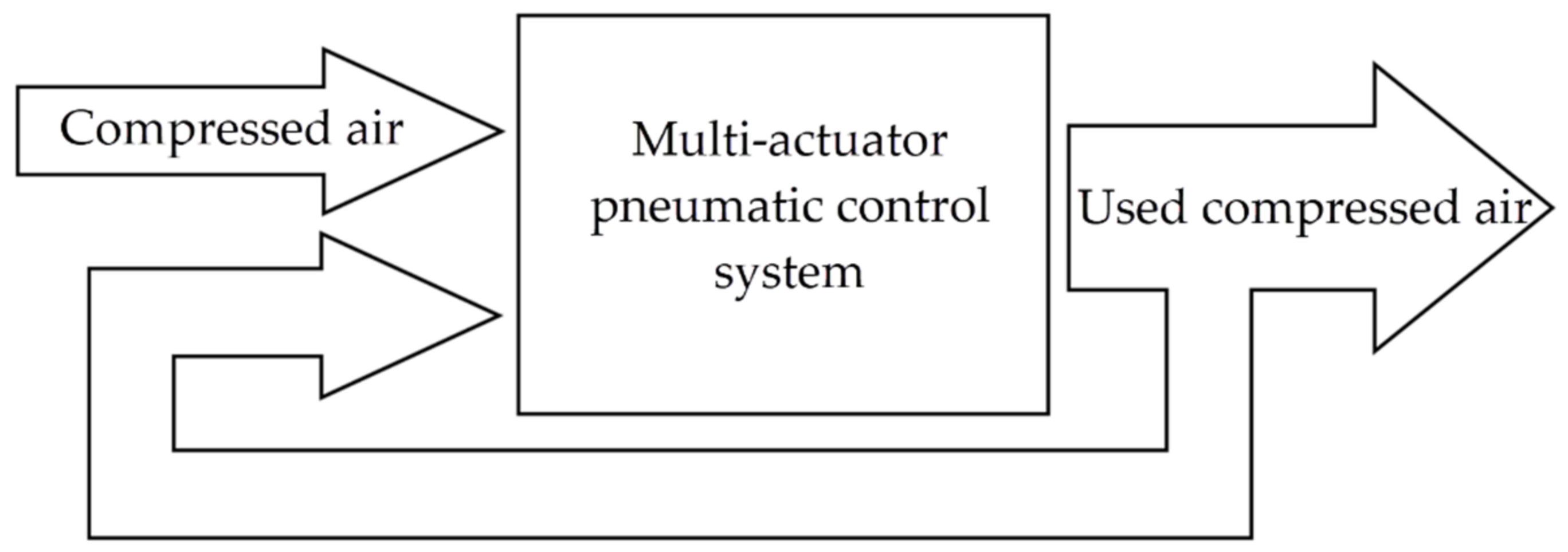
1.2. Concept of Increasing Energy Efficiency of Pneumatic Systems with Recovery of Compressed Air
1.3. Layout of the Paper
2. Experimental Setup
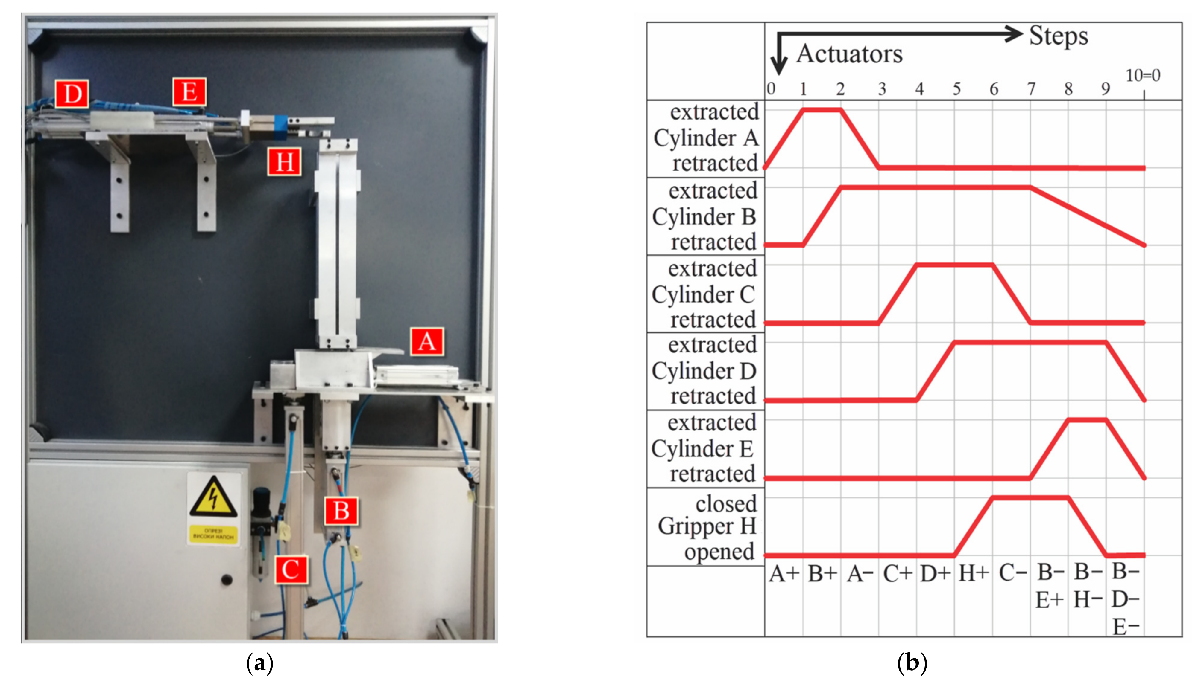
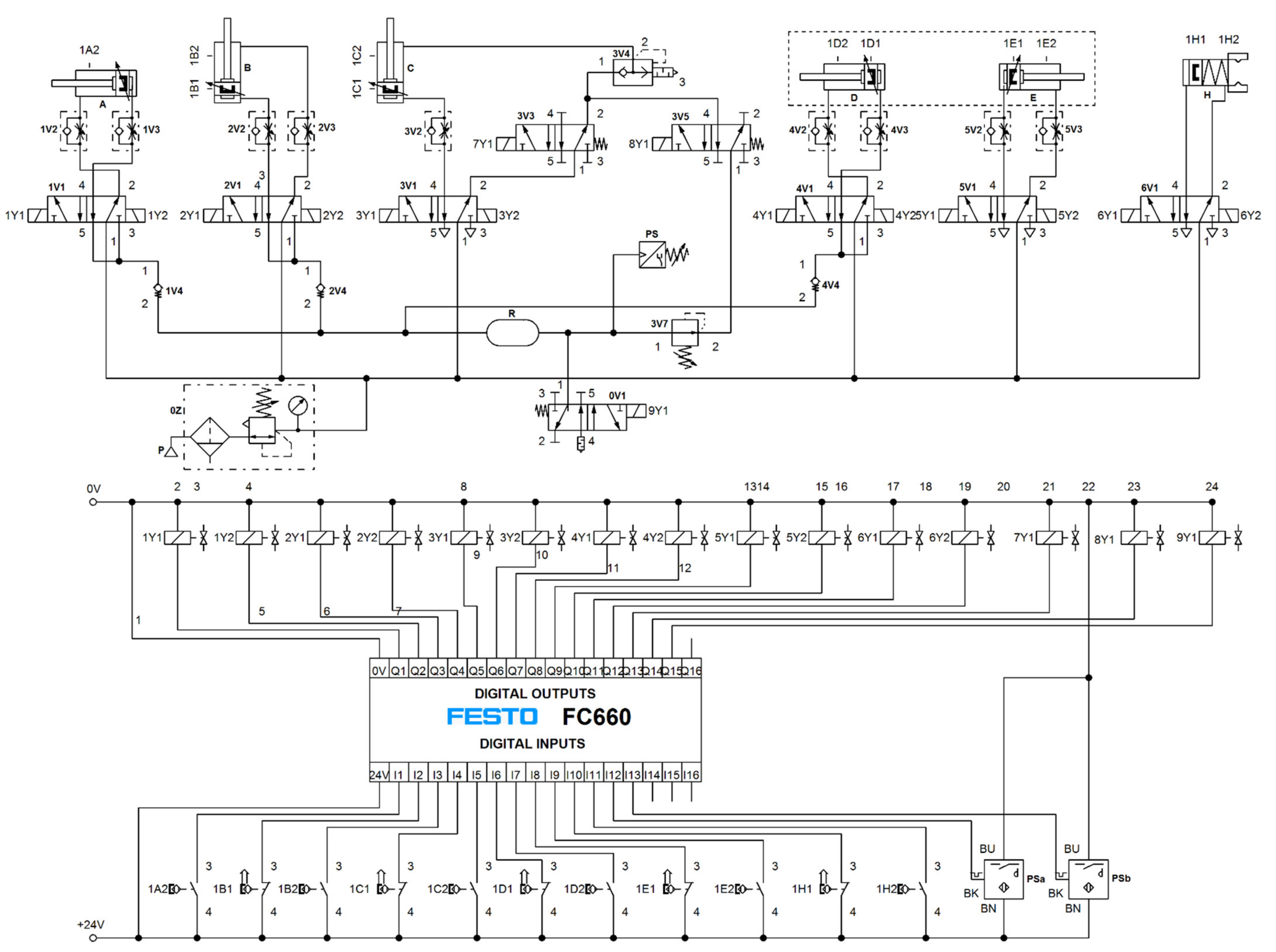
2.1. Description of the Manipulator Operation
- In the first step, the piston of the horizontally mounted double-acting cylinder (Figure 3a, position A) extracts and pushes one workpiece to the lifting position.
- Then, the vertically mounted double-acting cylinder (Figure 3a, position B) extracts and accepts the remaining five workpieces from the storage unit in order to ensure the smooth return of the cylinder A to its initial position. This cylinder is used to prevent the strong impact that the workpieces would create in the case of fast declining.
- The piston rod of the second vertically positioned double-acting cylinder (Figure 3a, position C) is extracted in the next step and lifts a workpiece to the top level. At this level, there is also a horizontally placed, multi-position cylinder made of two double-acting cylinders of identical characteristics (Figure 3a, positions D and E), which enable the realization of three different positions. The multi-position cylinder at its right end carries the gripper for gripping the workpieces (Figure 3a, position H).
- In the next step, the piston rod of cylinder D is extracted, and the gripper is brought to the position for taking the workpiece. Then, the clamp H closes and accepts the workpiece.
- After successfully accepting the workpiece, cylinder C is retracted, and cylinder B is then retracted. At the same time, cylinder E is extracted, which brings the workpiece to the top of the vertical storage unit. Gripper H opens and releases the workpiece that moves through the storage unit under the force of gravity.
- In the last step, the piston rods of cylinders D and E are simultaneously returned to their initial positions. This completes one working cycle. By repeating the previously described cycle, the workpiece circulation through the manipulator is enabled, hence the name.
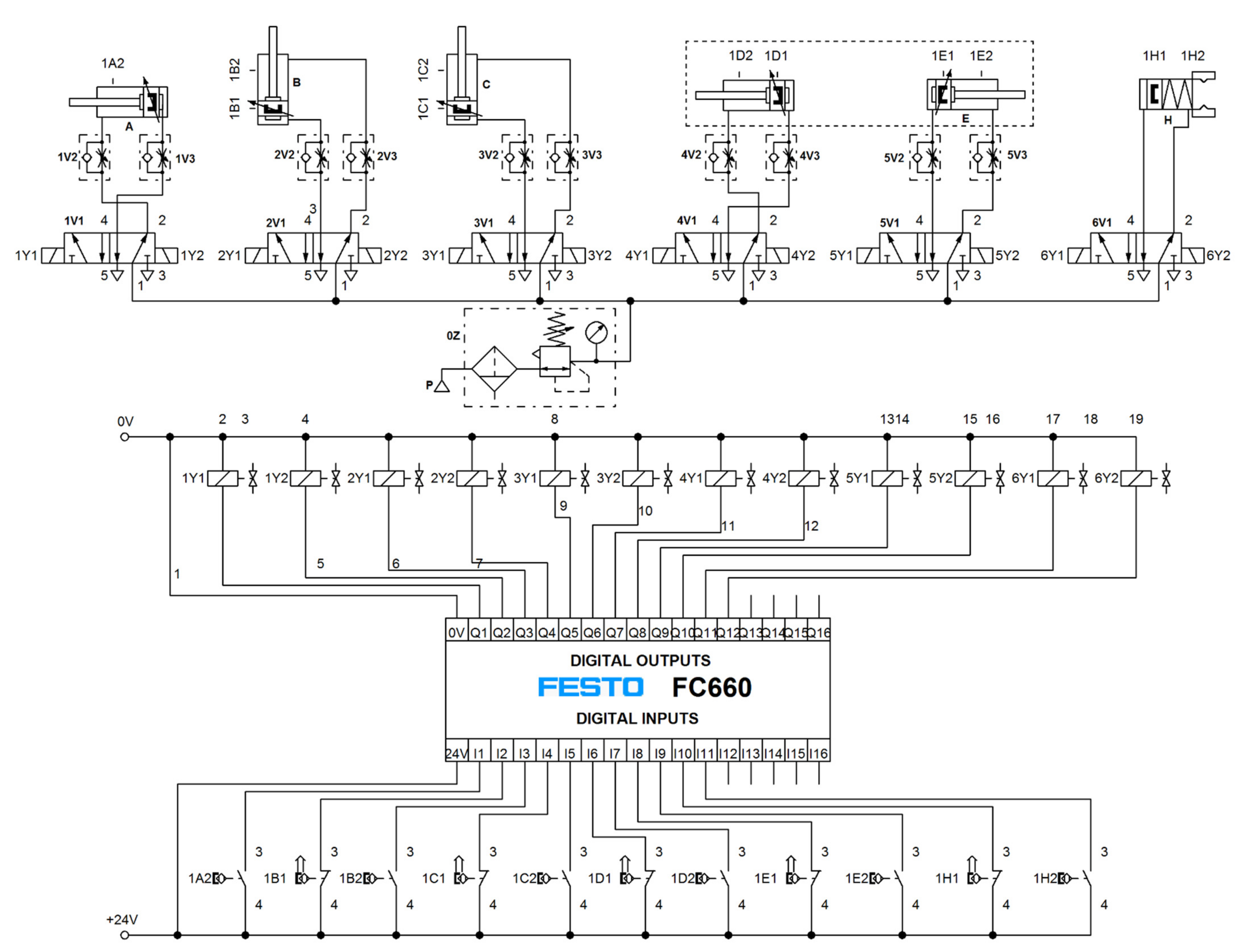
2.2. Initial Pneumatic Control Scheme
3. Conducting the Experiments
- The first part (Section 3.1), which refers to the determination of the minimum values of pressure necessary for the operation of pneumatic cylinders;
- The second part (Section 3.2), which deals with compressed air recovery in the closed circuit.
3.1. Determination of Minimum Pressure Values Necessary to Drive the Actuators
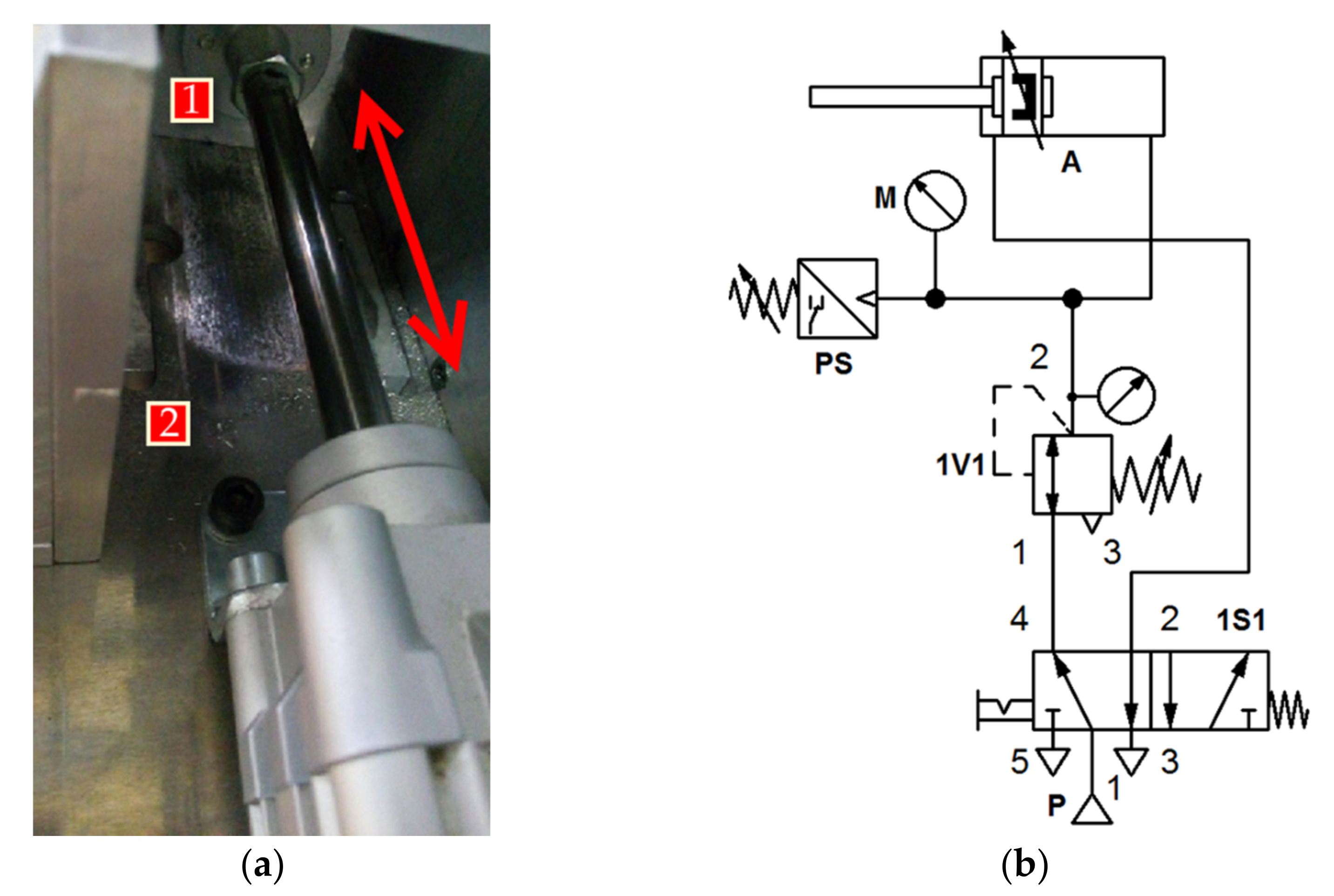
- Extracting the piston rod of cylinder A under the load of the workpiece;
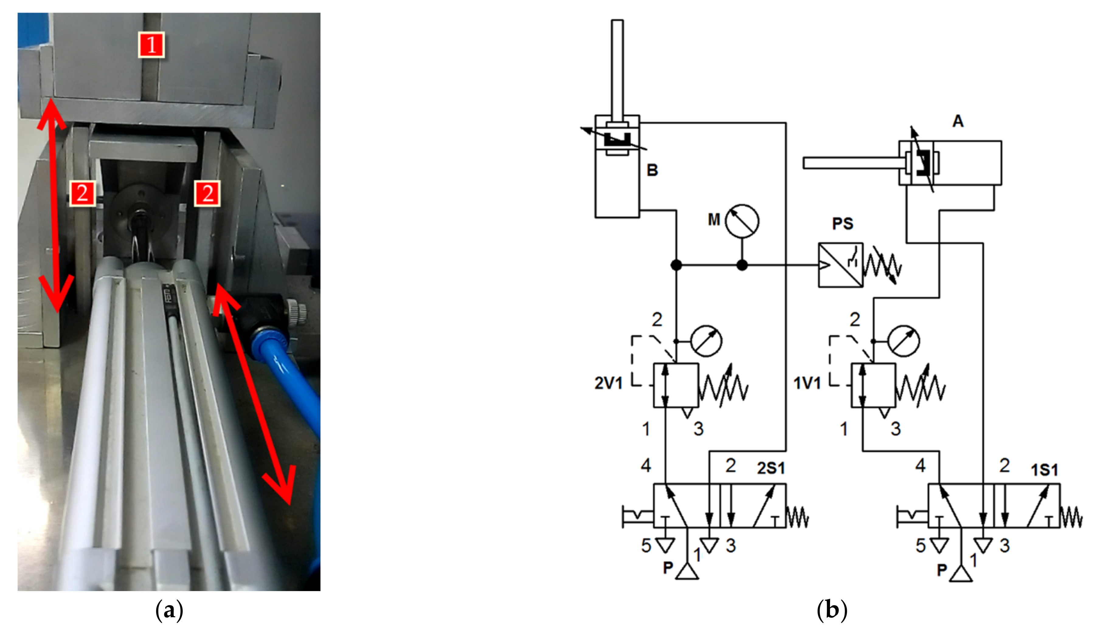
- Extracting the piston rod of cylinder B partially with the load of the workpiece;
- Retracting the piston rod of cylinder A without the load of the workpiece;
- Retracting the piston rod of cylinder B under the load of the workpiece;
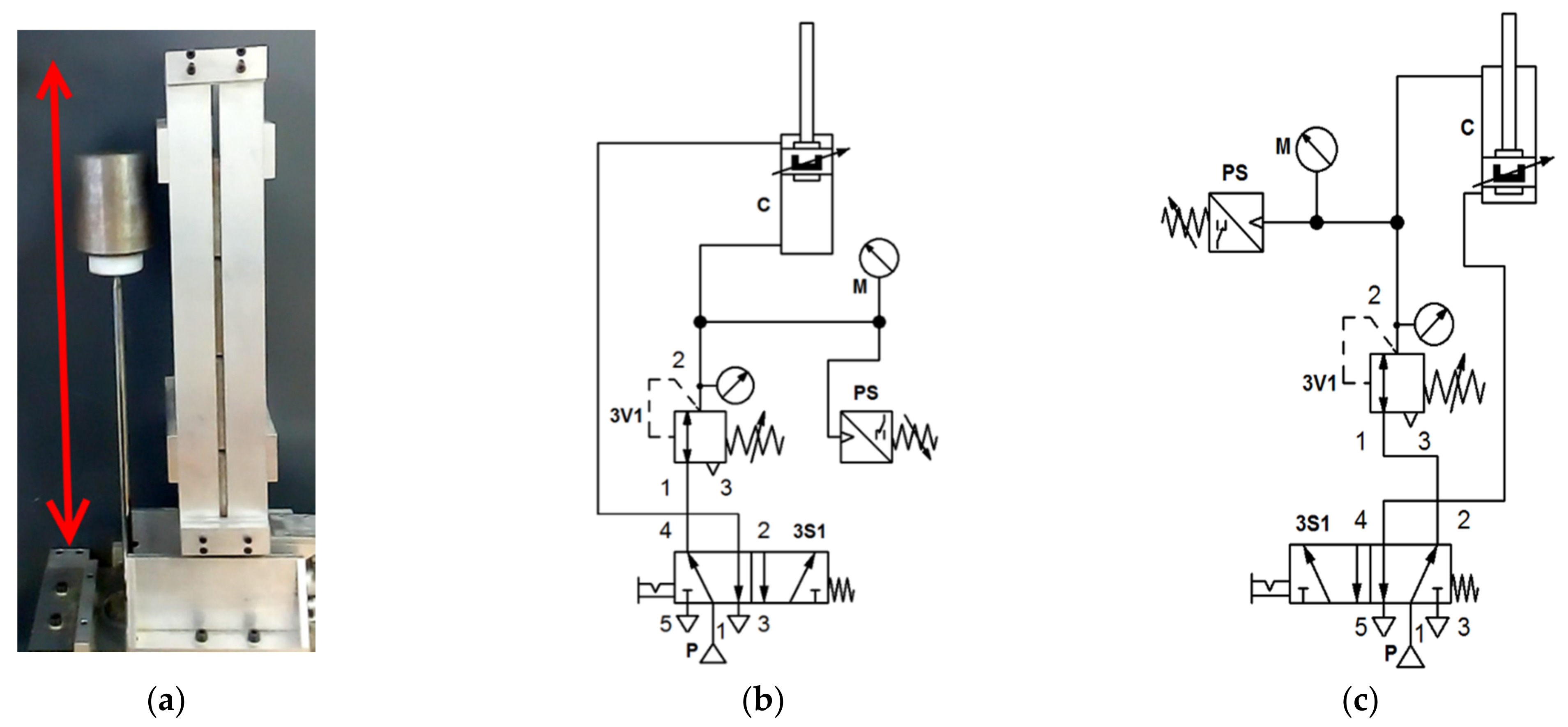
- Extracting the piston rod of cylinder C under the load of the workpiece;
- Retracting the piston rod of cylinder C without the load of the workpiece;
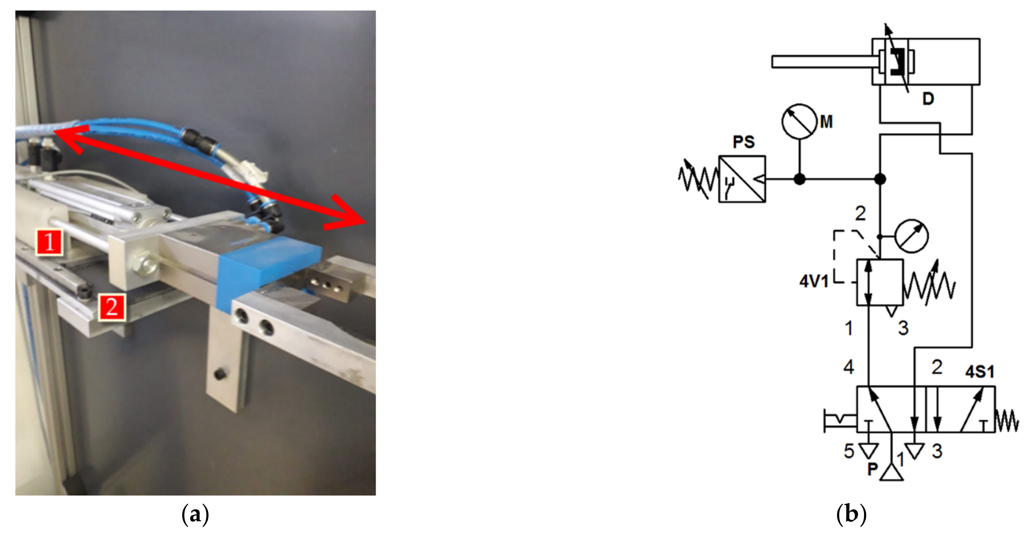
- Extracting the piston rod of cylinder D under the friction force produced by the construction itself;
- Extracting the piston rod of pneumatic cylinder E under the load of the workpiece;
- Retracting the piston rods of pneumatic cylinders D and E under the friction force produced by the construction itself.
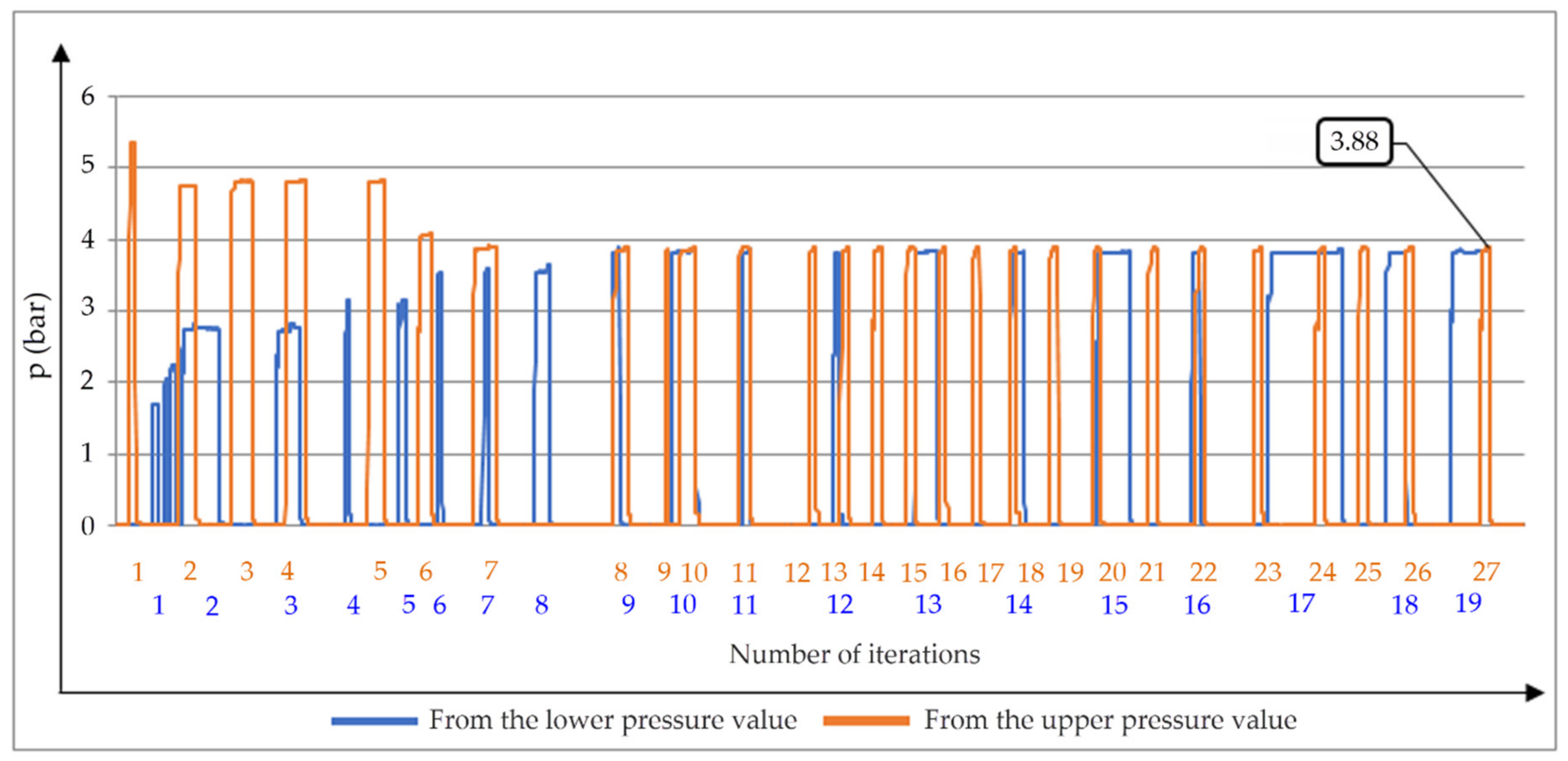
- In the first one, we started from the lowest pressure value (0.5 bar). It was gradually increased until the occurrence of so-called stick–slip effect;
- In the second one, we started from the highest recommended pressure value [30], typical for industrial use (6 bar), and it was gradually decreased until the stick–slip effect occurred.
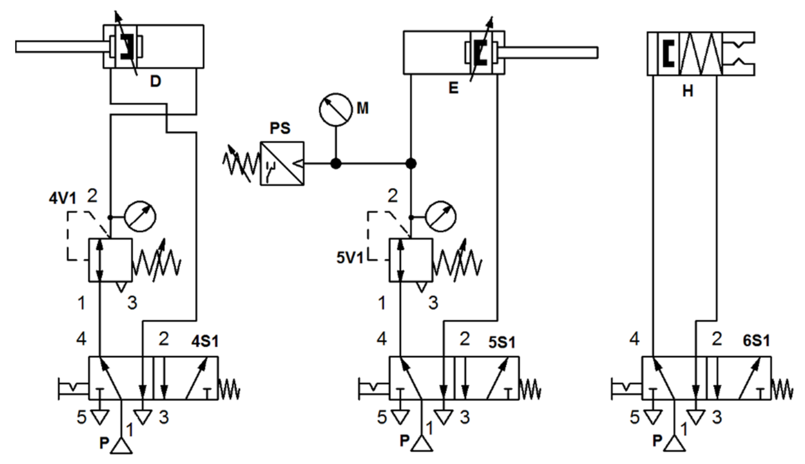
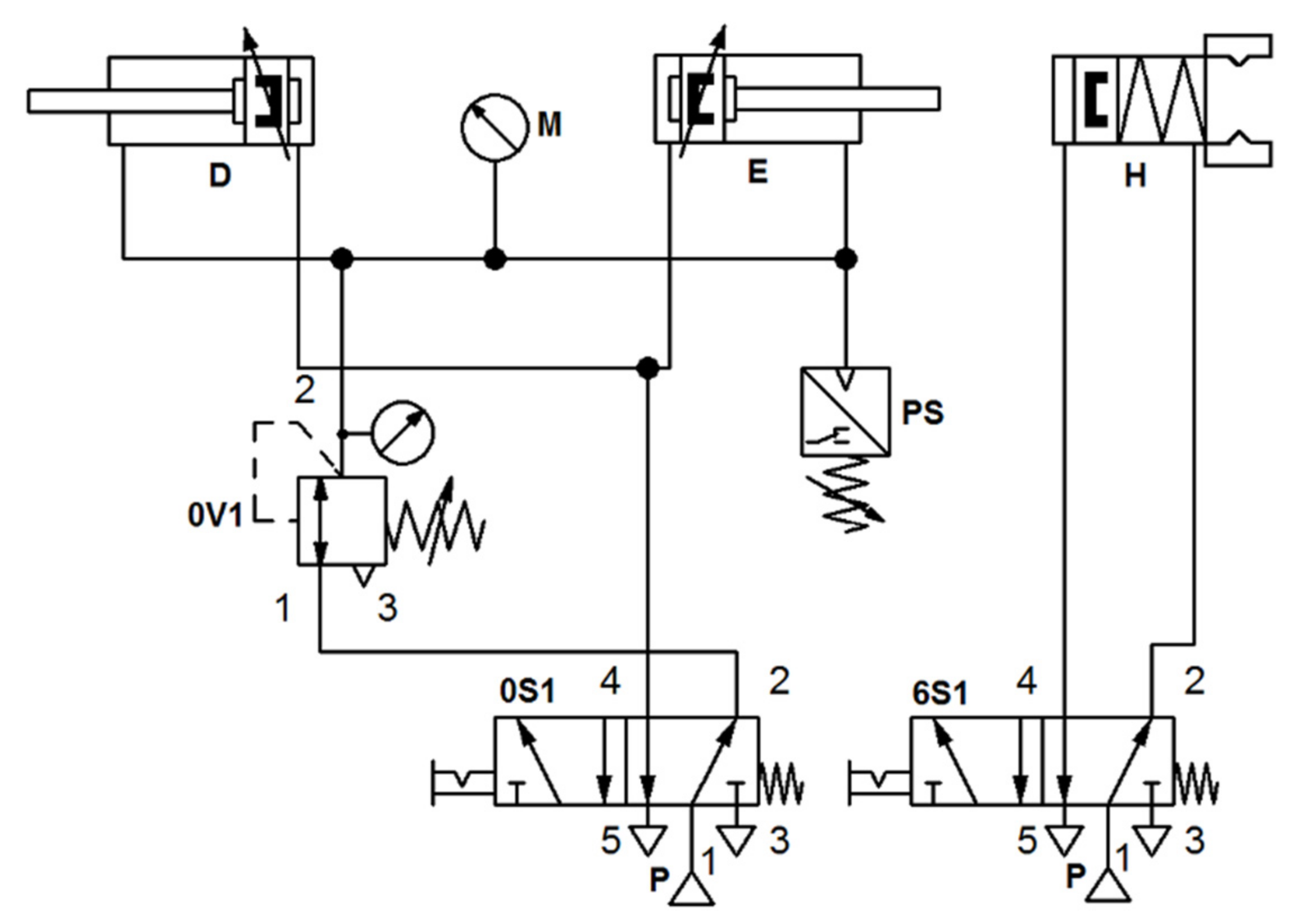
- Two mechanical pressure regulators with pressure gauge, order no. 539756, from the Festo didactic set;
- Three 5/2-way panel mounted valve with selector switch, order no. 152862, from the Festo didactic set;
- Pressure gauge, order no. 152865, from the Festo didactic set;
- Two pressure sensors, by DANFOSS, order no. MBS 3000 [31];
- PLC, by Festo, order no. FC660 Standard;
- Personal computer.
3.1.1. Cylinders A and B
3.1.2. Cylinder C
3.1.3. Cylinders D and E
3.2. Recovery of the Exhausted Compressed Air
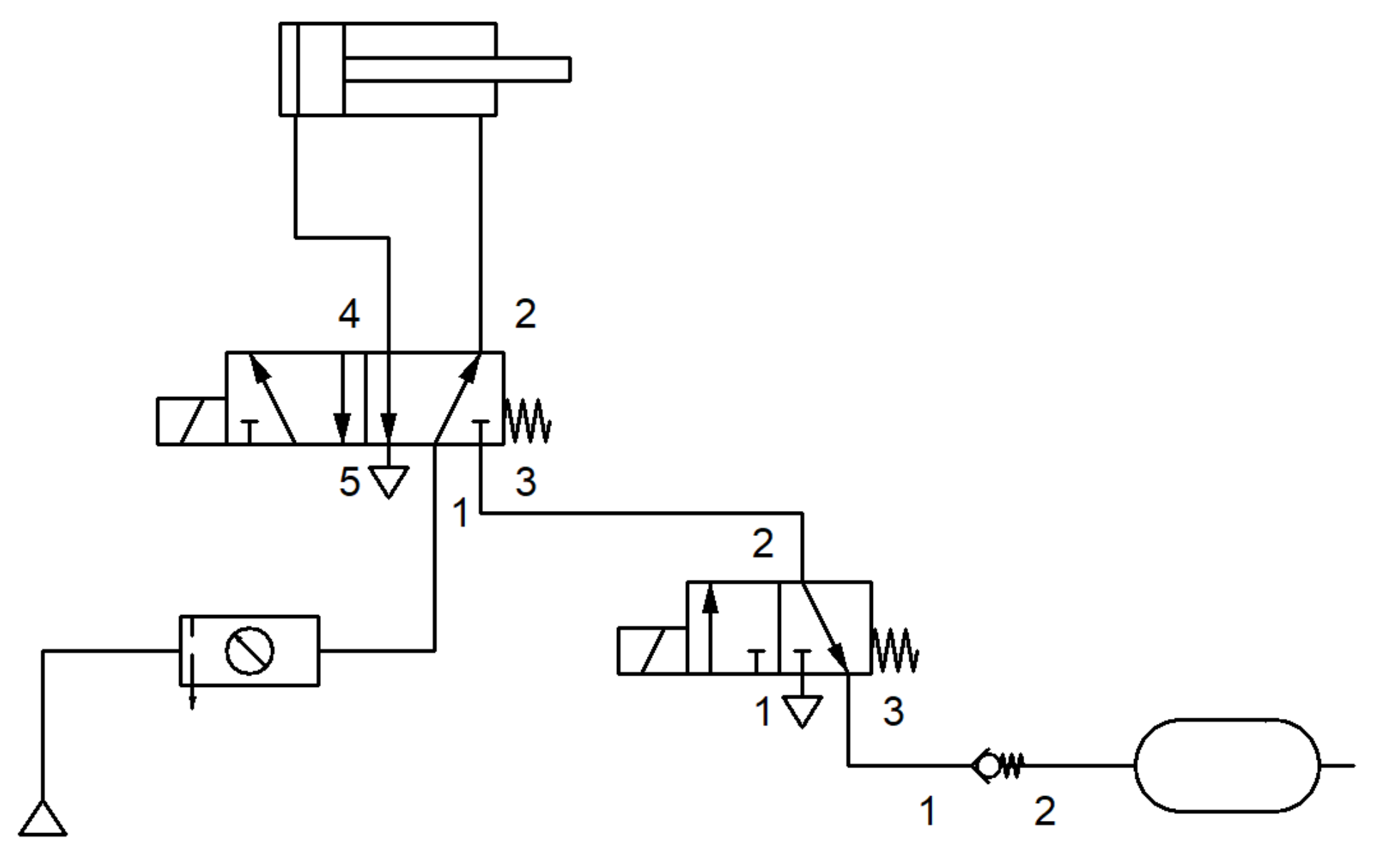
3.2.1. Basic Idea and Development of the New System
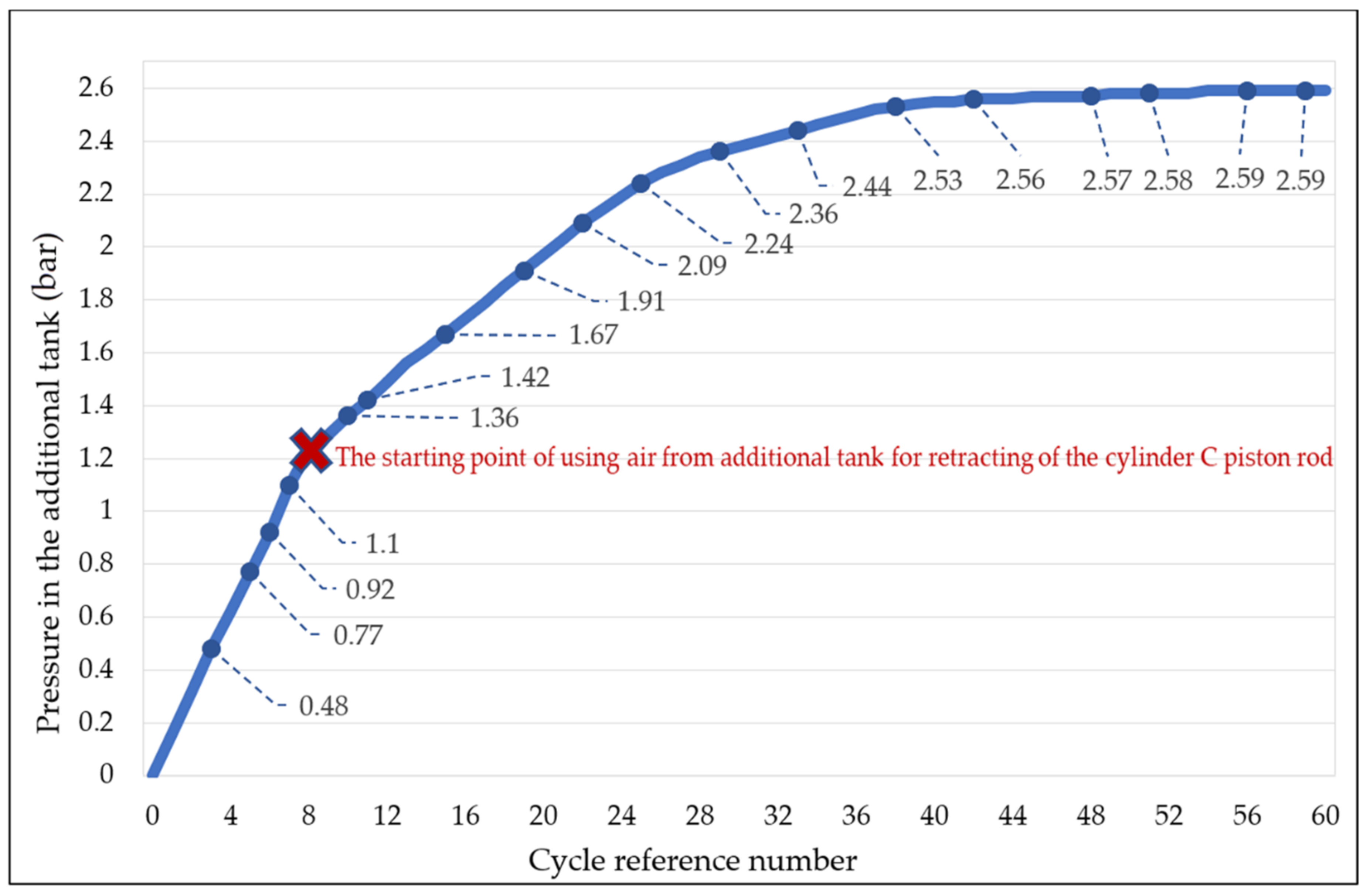
- The lower limit value allows uninterrupted control operation for which it is intended;
- The higher limit value (53% of the input pressure value, from the compressed air supply [25]) must not be exceeded in order to prevent violation of the system dynamics characteristics.
3.2.2. Pneumatic Control Scheme with the Recovery of the Exhausted Air
4. Results and Discussion
4.1. Minimum Pressure Values Necessary to Drive the Actuators
4.2. Compressed Air Consumption
- The Air Box was installed immediately after the service unit, i.e., at the entrance to the system.
- The system pressure was set to 6 bar.
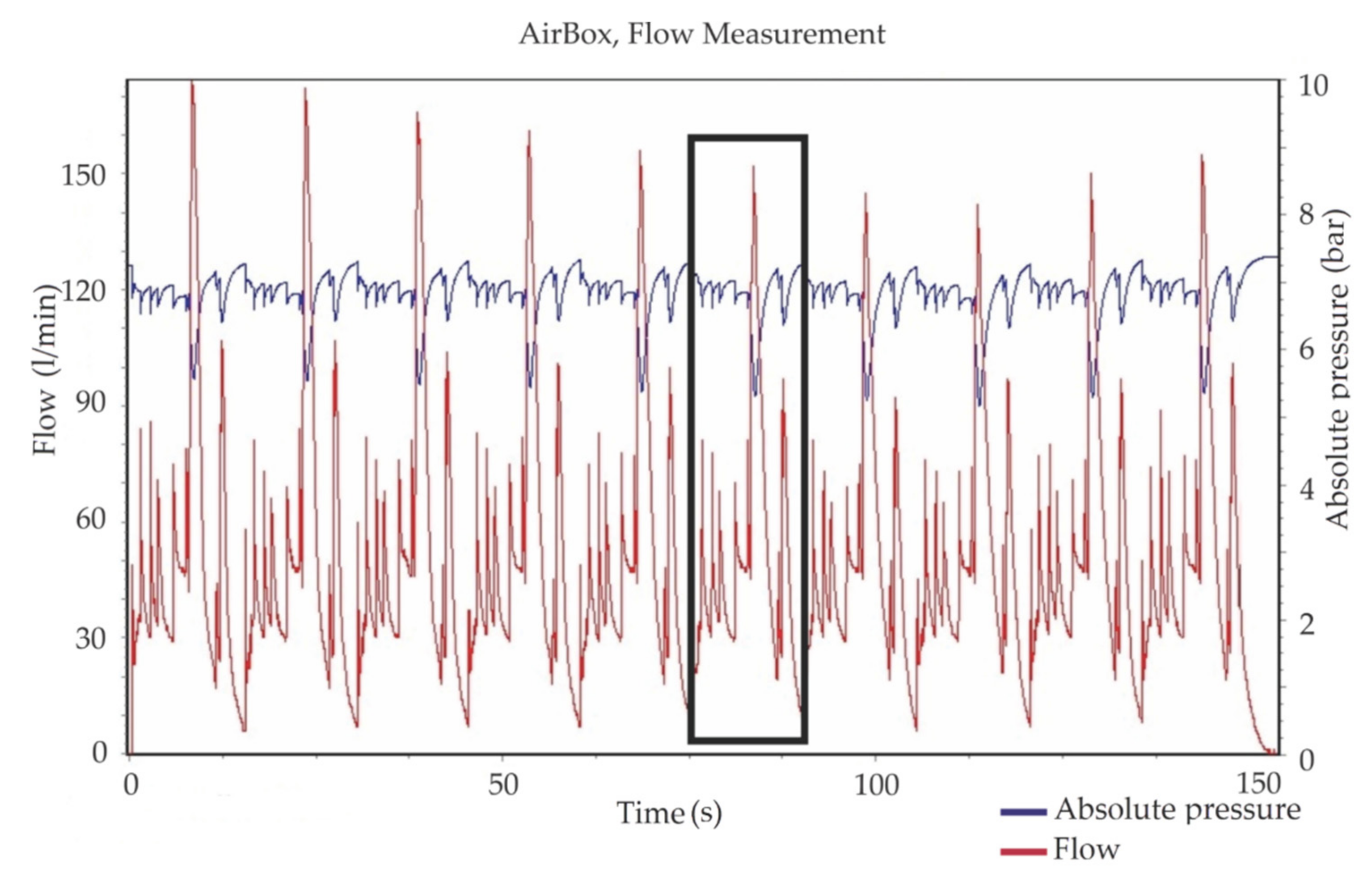
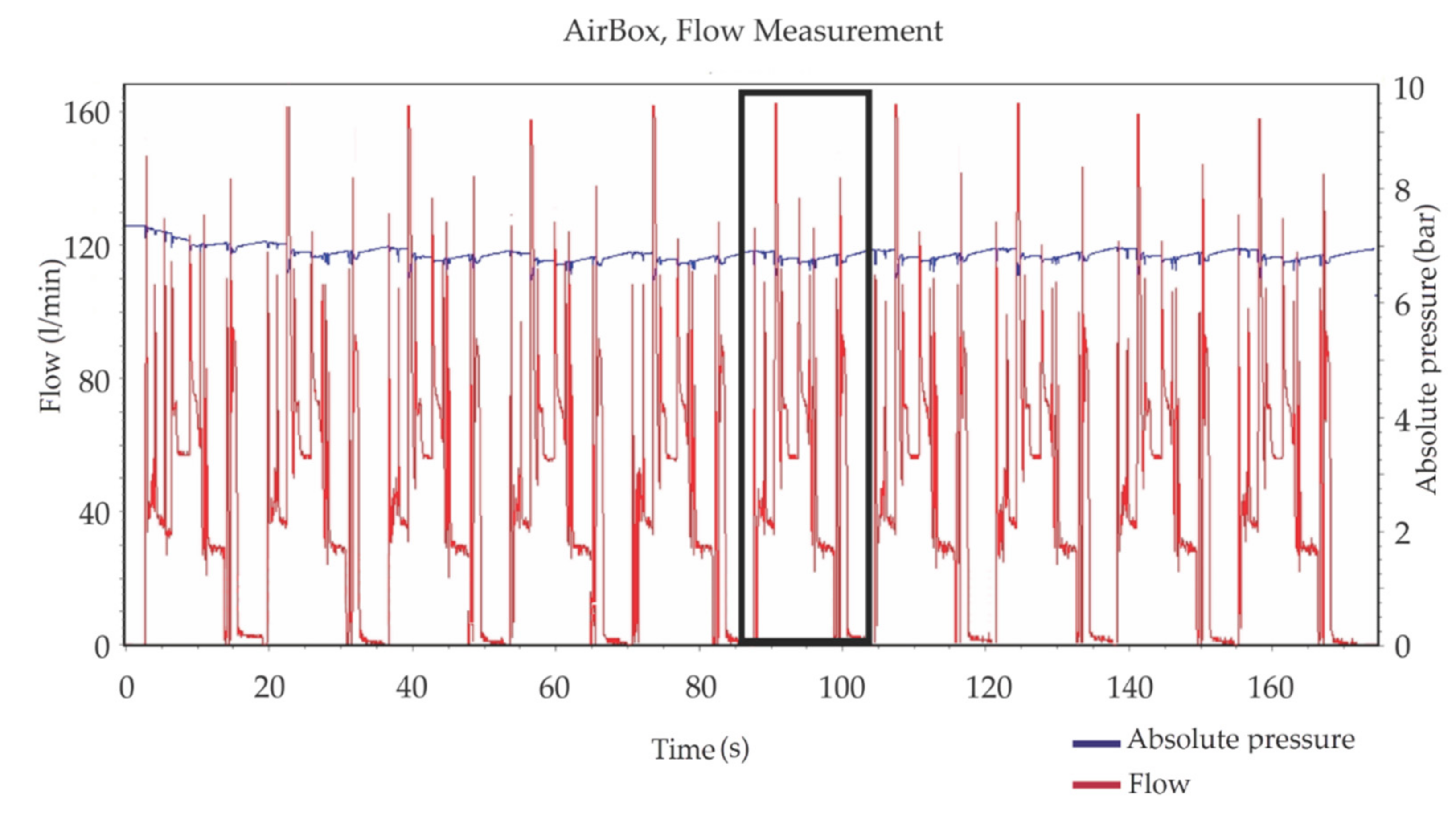
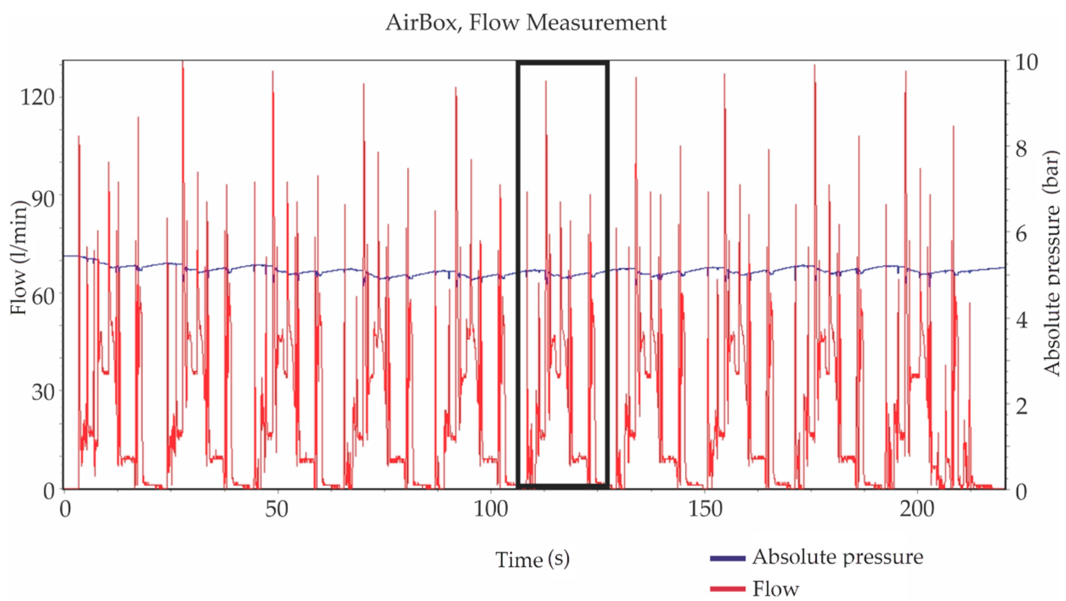
- In order to obtain accurate results, the manipulator was put into operation so that it was arbitrarily defined to perform 10 working cycles for one measurement.
- Data were recorded in the Air Box and then transferred to a PC in a spreadsheet (.csv file) and graphic (.jpg file) form.
- The graphs show the flow of compressed air in L/min (marked with a red curve) and pressure at the entrance to the Air Box (marked with a blue line), which is expressed as absolute pressure.
- In order to determine total compressed air consumption, the values shown in the graph need to be integrated to determine the surface below the curve (using the definite integral). Accordingly, the total compressed air consumption (in L), for one measurement, is calculated using the following formula:where is the total air consumption in l, is the time of measurement in s, is previous measurement time in s, is air flow in expressed in L/min, and air flow in expressed in L/min. Afterward, by dividing by the number of cycles, the consumption of compressed air was calculated for one working cycle.
- The measurement was repeated five times, and then, as the reference value, the mean arithmetic value of all the measured results was calculated. The deviation of all the results from the reference value was negligible.
- When the input pressure value was 6 bar;
- When the input pressure value was 4 bar (in accordance with the results obtained in the first part of the experiment).
- The lower limit value (after which the use of the collected air starts in order to initiate the backstroke of cylinder C) was set to 1.2 bar;
- The upper limit value (after which there would be a release of a certain amount of air from the tank to the atmosphere) was set to 2.12 bar (in case the input pressure in the system was 4 bar) or 3.18 bar (in case the input pressure in the system was 6 bar).
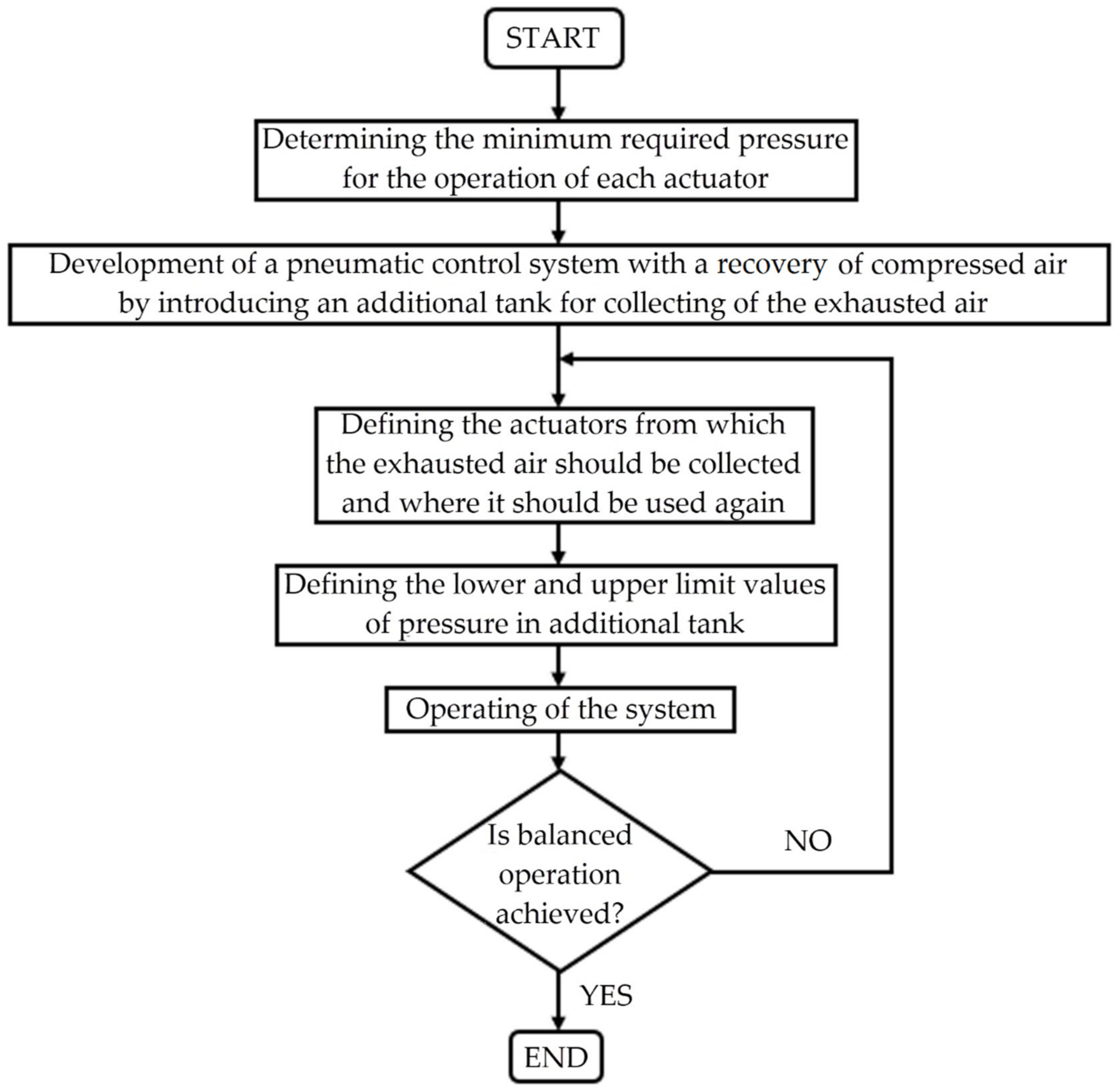
4.3. Systematic Approach for the Development of an Energy-Efficient System with Recovery of Compressed Air
- First, it is necessary to determine the minimal compressed air pressure values. Those values depend on the actuators and workpiece characteristics.
- In the next step, it is necessary to transform the initial pneumatic control scheme into a control scheme with the recovery of the exhausted air by adding appropriate components, such as non-return valves, 2/2-way valves, quick exhaust valves, pressure sensors, and pressure regulators. With the correct component connections, the newly obtained scheme must allow for collecting the exhausted air from some actuators (non-return valves allow compressed air flow only when directed to the additional tank) and reusing the collected compressed air for operation of some actuators (2/2-way valves allow either air supply from the additional tank or a compressed air supply, and the quick exhaust valves allow the compressed air to be exhausted from the actuator chambers in the appropriate time).
- Before starting the system, it is necessary to define boundary compressed air pressure values (the upper and lower limit pressure values) in the additional tank. The lower limit value needs to allow sufficient compressed air for starting the motion of the chosen actuators. The upper limit value must not exceed 53% of the minimally required input pressure value (determined in step 1).
- Finally, the system should be started. The system operation is constantly monitored and checked for malfunction and whether balanced operation is achieved (if the compressed air pressure value is kept within the defined limits). If balanced operation is not achieved, the algorithm is repeated from step 2.
5. Conclusions
- The compressed air consumption of the recovery system at an input pressure of 6 bar, compared to the basic system, was reduced by 2.71 L per cycle of operation of the manipulator, which represented a 22% saving.
- When considering a systematic approach and determination of the minimum forces required to start the motion of the cylinders, a minimum pressure value of 4 bar was set for the input pressure of the recovery system, which enabled safe and undisturbed operation of the manipulator. The consumption of such a recovery system, compared to the basic system, was reduced by 4.54 L per cycle of operation of the manipulator, or by 37%.
- Balanced operation of the pneumatic control system was achieved because the pressure in the tank never exceeded the upper limit value, and there was no need for additional air discharge from the tank, which would result in additional energy loss. If the system were to start with a partially charged tank (to a lower pressure value), the backstroke of the cylinder C piston rod would be, from the very beginning, achieved by the collected air in the tank.
- With the accomplishment of this kind of recovery mode, the energy losses in the system, generated by the release of compressed air into the atmosphere, were minimal. They only appeared while lifting the workpiece and returning the piston rod to its inner-end position (cylinder C), gripping and releasing the workpiece (pneumatic gripper H), and moving the workpiece to the top of the storage tray and returning the piston rod to its forward-end position (cylinder E), because the exhausted air from those ports was not included in the recovery system.
- The main disadvantage of the proposed approach is the increase of the cycle duration period that occurred due to compressed air pressure reduction and changed in the system characteristics. The average time of a manipulator operating cycle with a recovery system with an input pressure of 6 bar, compared to the basic system, was increased by 1.8 s, or 12%. The average time of a manipulator operating cycle with a recovery system with an input pressure of 4 bar, compared to the basic system, was increased by 5.7 s, or 38%.
Author Contributions
Funding
Institutional Review Board Statement
Informed Consent Statement
Data Availability Statement
Conflicts of Interest
References
- Saidur, R.; Rahim, N.A.; Hasanuzzaman, M. A review on compressed-air energy use and energy savings. Renew. Sustain. Energy Rev. 2010, 14, 1135–1153. [Google Scholar] [CrossRef]
- Radgen, P.; Blaustein, E. Compressed Air Systems in the European Union, Energy, Emissions, Savings Potential and Policy Actions; Fraunhofer Institute for Systems Technology and Innovation: Stutgart, Germany, 2001. [Google Scholar]
- Taheri, K.; Gadow, R. Industrial compressed air system analysis: Exergy and thermoeconomic analysis. CIRP J. Manuf. Sci. Technol. 2017, 18, 10–17. [Google Scholar] [CrossRef]
- Mousavi, S.; Kara, S.; Kornfeld, B. Energy Efficiency of Compressed Air Systems. Procedia CIRP 2014, 15, 313–318. [Google Scholar] [CrossRef]
- Dudić, S.; Reljić, V.; Šešlija, D.; Dakić, N.; Blagojević, V. Improving Energy Efficiency of Flexible Pneumatic Systems. Energies 2021, 14, 1819. [Google Scholar] [CrossRef]
- Leszczynski, J.S.; Grybos, D. Compensation for the complexity and over-scaling in industrial pneumatic systems by the accumulation and reuse of exhaust air. Appl. Energy 2019, 239, 1130–1141. [Google Scholar] [CrossRef]
- Ignjatović, I.; Komenda, T.; Šešlija, D.; Malisa, V. Optimisation of compressed air and electricity consumption in a complex robotic cell. Robot. Comput. Integr. Manuf. 2013, 29, 70–76. [Google Scholar] [CrossRef]
- Al-Dakkan, K.A.; Barth, E.J.; Goldfarb, M. Dynamic Constraint-Based Energy-Saving Control of Pneumatic Servo Systems, ASME. J. Dyn. Syst. Meas. Control 2006, 128, 655–662. [Google Scholar] [CrossRef][Green Version]
- Du, H.; Xiong, W.; Jiang, Z.; Li, Q.; Wang, L. Energy efficiency control of pneumatic actuator systems through nonlinear dynamic optimization. J. Clean. Prod. 2018, 184, 511–519. [Google Scholar] [CrossRef]
- Belforte, G.; Eula, G. Smart Pneutronic Equipments and Systems for Mechatronic Applications. J. Control Eng. Appl. Inform. 2012, 14, 70–79. [Google Scholar]
- Salvatori, S.; Benedetti, M.; Bonfa, F.; Introna, V.; Ubertini, S. Inter-sectorial benchmarking of compressed air generation energy performance: Methodology based on real data gathering in large and energy-intensive industrial firms. Appl. Energy 2018, 217, 266–280. [Google Scholar] [CrossRef]
- Endler, L.; De Negri, V.J.; Castelan, E.B. Compressed air saving in symmetrical and asymmetrical pneumatic positioning systems. Proc. Inst. Mech. Eng. Part I J. Syst. Control Eng. 2015, 229, 957–969. [Google Scholar] [CrossRef]
- Kanno, T.; Hasegawa, T.; Miyazaki, T.; Yamamoto, N.; Haraguchi, D.; Kawashima, K. Development of a Poppet-Type Pneumatic Servo Valve. Appl. Sci. 2018, 8, 2094. [Google Scholar] [CrossRef]
- Dvorák, L.; Fojtášek, K. Pressure Regulators as Valves for Saving Compressed Air and their Influence on System Dynamics; EFM14—Experimental Fluid Mechanics 2014. EPJ Web Conf. 2015, 92, 02015. [Google Scholar] [CrossRef]
- Ho, T.H.; Ahn, K.K. Modeling and simulation of hydrostatic transmission system with energy regeneration using hydraulic accumulator. J. Mech. Sci. Technol. 2010, 24, 1163–1175. [Google Scholar] [CrossRef]
- Merit, E. Hydraulic Control Systems; John Wiley&Sons, Inc.: New York, NY, USA, 1967. [Google Scholar]
- Do, T.C.; Nguyen, D.G.; Dang, T.D.; Ahn, K.K. A Boom Energy Regeneration System of Hybrid Hydraulic Excavator Using Energy Conversion Components. Actuators 2021, 10, 1. [Google Scholar] [CrossRef]
- Agostini, T.; De Negri, V.; Minav, T.; Pietola, M. Effect of Energy Recovery on Efficiency in Electro-Hydrostatic Closed System for Differential Actuator. Actuators 2020, 9, 12. [Google Scholar] [CrossRef]
- Festo. Available online: https://www.festo.com/net/SupportPortal/Files/640429/EEF_V02_en_M.pdf (accessed on 25 February 2021).
- Blagojević, V.; Šešlija, D.; Stojiljković, M.; Dudić, S. Efficient control of servo pneumatic actuator system utilizing by-pass valve and digital sliding mode. Sadhana Acad. Proc. Eng. Sci. 2013, 38, 187–197. [Google Scholar] [CrossRef]
- Shi, Y.; Li, X.; Teng, Y. Research on pneumatic cylinder’s exhausted-air reclaiming control devices. In Proceedings of the 6th International Symposium on Fluid Power—JFPS, Tsukuba, Japan, 7–10 November 2005; pp. 558–563. [Google Scholar] [CrossRef]
- Li, T.C.; Wu, H.W.; Kuo, M.J. A study of gas economizing pneumatic cylinder. J. Phys. Conf. Ser. 2006, 48, 1227–1232. [Google Scholar] [CrossRef]
- Yang, F.; Tadano, K.; Li, G.; Kagawa, T.; Peng, J. Simulation on the Characteristics of Pneumatic Booster Valve with Energy Recovery. In Proceedings of the 16th Asia Simulation Conference and SCS Autumn Simulation Multi-Conference, Beijing, China, 8–11 October 2016; pp. 143–153. [Google Scholar]
- Yang, F.; Tadano, K.; Li, G.; Kagawa, T. Analysis of the Energy Efficiency of a Pneumatic Booster Regulator with Energy Recovery. Appl. Sci. 2017, 7, 816. [Google Scholar] [CrossRef]
- Novaković, M.; Šešlija, D.; Čajetinac, S.; Todorović, M. Impact of Capturing Used Air on the Dynamics of Actuator Drive. Control Eng. Appl. Inform. 2015, 17, 82–89. [Google Scholar]
- Reljić, V.; Bajči, B.; Milenković, I.; Šulc, J.; Šešlija, D.; Dudić, S. Development of an Experimental Setup for Remote Testing Pneumatic Control. Int. J. Online Eng. 2018, 14, 195–202. Available online: https://online-journals.org/index.php/i-joe/article/view/7784 (accessed on 20 January 2021). [CrossRef]
- Festo. Available online: https://www.festo.com/net/supportportal/files/10019/fec-standard_enus.pdf (accessed on 8 March 2021).
- Plagemann, B. FST4 Manual; Festo: Esslingen, Germany, 2004. [Google Scholar]
- Plagemann, B. Festo Software Tools; Festo: Esslingen, Germany, 2004. [Google Scholar]
- Ebel, F.; Idler, S.; Prede, G.; Scholz, D. Pneumatik Elektropneumatik-Grundlagen. In Bildungsverlag EINS, Festo, 3rd ed.; Bildungsverlag EINS GmbH: Troisdorf, Germany, 2017. [Google Scholar]
- Available online: https://assets.danfoss.com/documents/156946/AI308930736185en-000201.pdf?_ga=2.6780666.911630632.1618822350-153542798.1618822350 (accessed on 12 March 2021).
- Festo. Air Box Type GHDA-FQ-M-FDMJ-A—Operating Instructions; Festo: Esslingen, Germany, 2006. [Google Scholar]



| Component | Working Operation | Limit Pressure Value (bar) | Minimum Required Force (N) |
|---|---|---|---|
| Cylinder A | Piston rod extracting | 3.88 | 312.05 |
| Piston rod retracting | 2.14 | 172.11 | |
| Cylinder B | Piston rod extracting | 2.03 | 163.26 |
| Piston rod retracting | - | - | |
| Cylinder C | Piston rod extracting | 1.05 | 84.44 |
| Piston rod retracting | 0.60 | 48.25 | |
| Cylinder D | Piston rod extracting | 1.40 | 112.59 |
| Piston rod retracting | 1.93 | 155.22 | |
| Cylinder E | Piston rod extracting | 1.48 | 119.02 |
| Piston rod retracting | 1.93 | 155.22 |
| Component | Working Operation | Limit Pressure Value (bar) |
|---|---|---|
| Cylinder A | Piston rod extracting | 4 |
| Piston rod retracting | 2.3 | |
| Cylinder B | Piston rod extracting | 2.2 |
| Piston rod retracting | - | |
| Cylinder C | Piston rod extracting | 1.2 |
| Piston rod retracting | 0.8 | |
| Cylinder D | Piston rod extracting | 1.6 |
| Piston rod retracting | 2.1 | |
| Cylinder E | Piston rod extracting | 1.6 |
| Piston rod retracting | 2.1 |
Publisher’s Note: MDPI stays neutral with regard to jurisdictional claims in published maps and institutional affiliations. |
© 2021 by the authors. Licensee MDPI, Basel, Switzerland. This article is an open access article distributed under the terms and conditions of the Creative Commons Attribution (CC BY) license (https://creativecommons.org/licenses/by/4.0/).
Share and Cite
Šešlija, M.; Reljić, V.; Šešlija, D.; Dudić, S.; Dakić, N.; Jovanović, Z. Reuse of Exhausted Air from Multi-Actuator Pneumatic Control Systems. Actuators 2021, 10, 125. https://doi.org/10.3390/act10060125
Šešlija M, Reljić V, Šešlija D, Dudić S, Dakić N, Jovanović Z. Reuse of Exhausted Air from Multi-Actuator Pneumatic Control Systems. Actuators. 2021; 10(6):125. https://doi.org/10.3390/act10060125
Chicago/Turabian StyleŠešlija, Milan, Vule Reljić, Dragan Šešlija, Slobodan Dudić, Nikolina Dakić, and Zoran Jovanović. 2021. "Reuse of Exhausted Air from Multi-Actuator Pneumatic Control Systems" Actuators 10, no. 6: 125. https://doi.org/10.3390/act10060125
APA StyleŠešlija, M., Reljić, V., Šešlija, D., Dudić, S., Dakić, N., & Jovanović, Z. (2021). Reuse of Exhausted Air from Multi-Actuator Pneumatic Control Systems. Actuators, 10(6), 125. https://doi.org/10.3390/act10060125


