1. Introduction
Considering the advantages of low cost, high precision, and high torque output, stepper motors are frequently used in the field of high-precision control. Traditional open-loop control can lead to momentary step loss or position error when the load changes. As a result, the stepper motor drive system for position and speed control loops has been gradually enhanced as a closed-loop control [
1,
2,
3,
4,
5]. In Ref. [
1], PI controllers are applied for the current and speed closed-loop control, and P control for the position control loop. For Ref. [
2], the closed-loop control structure and PI controllers with motor parameter identification are applied to the current and position control of a two-phase bipolar hybrid stepper motor. Furthermore, feedforward compensation is used for the damping control such that the motor can be operated at a high speed range. The authors of Ref. [
3] adopted the fuzzy-sliding mode observer to estimate the motor velocity and fed it back as a speed closed-loop system. In that system, PI controllers are used for the stationary A–B phase current control. In Ref. [
4], the authors proposed a wide speed range closed-loop-control drive system, and implemented by a field programmable gate array (FPGA) chip. For low-speed operation, the speed control loop is bypassed, and for the high-speed operation, the field-weaken vector control is used to reach the desired performance. Regarding Ref. [
5], it proposed a simple torque control method with shaft-position feedback to correct the load angle, and was also realized by FPGA. In Ref. [
6], the PID controller and feedforward control are applied to the stepper motor current control to guarantee the desired current response.
For most of the AC motor drive systems, such as induction motor (IM) and permanent magnet synchronous motor (PMSM)-based systems, vector control is widely used. For such systems, a three-phase modulator is usually used to generate the desired d-axis and q-axis voltages. Clarke and inverse Clarke matrices are used for the transformation between the three-phase and two-phase systems. For a two-phase hybrid stepper motor, it only needs a two-axis modulator mainly made by two H-bridge inverters to convert the DC bus voltage into a pair of quadrature voltages for the two stator coils. Thus, the stepper motor drive system can be operated without executing the conversion of a three-phase stationary (a-b-c) coordinate system into two-phase stationary () coordinate system. Regarding the vector control for the stepper motor drive system, for the implementation of the vector control in the stepper motor, only Park and inverse Park matrices are required.
The cogging force of the hybrid stepper motor affects the accuracy of positioning. Moreover, for the vector control protocol, the coordinate transformation requires the position feedback to convert the stationary
-axis signals into synchronous rotary dq-axis signals. For a closed-loop stepper motor drive system, a high-precision incremental encoder can be used to improve the positioning accuracy. However, the coordinate transformation performs the sin/cos calculation. This requires the position feedback, and the resolution of the sin/cos table holds the precision of the transformation. Additionally, a high-resolution position feedback by incremental encoder is hard to produce the same resolution of voltage generation because of the precision limitations of the space vector pulse width modulation (SVPWM) hardware system, and that leads the current control to not be as precise as the position control loop. As a result, a high-performance variable structure controller is used to improve the positioning accuracy regarding the existence of the problems mentioned above. The variable structure control (VSC) has the advantages of insensitivity to parameter changes, external interference suppression and fast dynamic response [
7]. The VSC or sliding mode control (SMC) has been widely applied to single-motor drive design [
8,
9,
10], or designed for a system such as Ref. [
11] which is applied to the balance control of a two-wheel vehicle system. For systems controlled by VSC, some steps are included into the design procedure. First, a mathematic model for the control system is presented. Second, a sliding surface or switching surface which dynamics is equivalent to the desired system performances is made. Third, a control law to guarantee the existence of the sliding mode is made. Sometimes, a VSC system exists in the reaching phase and sliding phase, and the system performance is guaranteed on its sliding phase but not on its reaching phase [
7,
8]. Furthermore, finding an easy way to shape the desired system dynamics is also important for VSC systems. Thus, for the proposed algorithm, the design procedure of a stepper motor drive system is demonstrated step by step. The controlled system is first represented into state space form, and the linear state feedback control method is applied to find the desired system dynamics and switching surface. Finally, a control law which combines the linear control and VSC is designed to make the sliding condition occur.
Hardware circuits realized by field programmable gate array (FPGA) have the benefit of fast prototyping with digital structure, verified with ease. In addition to associating with some of the high-level programming languages, such as C/C++ or MATLAB/Simulink, control systems designed and represented by hardware description language (HDL) are easily achieved. Furthermore, owing to the development of high-density and high-performance FPGA [
12,
13,
14], hardware controllers implemented by FPGA are widely obtained. Some examples include the design of velocity estimation [
15], virtual anemometer [
16], PID controller [
17] and fuzzy controller [
18]. FPGA is also suitable for the control system realization of power electronic circuits [
19]. In this paper, we first constructed the mathematical model of a hybrid stepper motor and its drive control system in Simulink [
4,
9]. Next, the models of the controllers were then digitized to be converted into Verilog HDL codes to meet the requirements of hardware design resources. Finally, the designed hardware circuit was used to implement the position, speed and current control to illustrate the correctness of the hardware circuit design and the performance of the variable structure controller. The performances are mainly demonstrated by a 4-ch digital oscilloscope with logical input. The main contributions of the proposed model are based on the state space motor model to the position and speed control, and the applied variable structure controller reaching the desired position and speed performance. The current loop is based on a two-phase vector control strategy where the d- and q-axis loops are controlled separately. The designed system was successfully implemented on FPGA and evaluated by hybrid stepper motor control platform.
The further contents of the paper are as follows: in
Section 2, the modeling of the hybrid stepper motor is shown, and the variable structure controller for position/speed control is introduced.
Section 3 gives the position variable structure controller design. The simulations on MATLAB/Simulink platform of the proposed are given in
Section 4. The experimental setup and results are shown in
Section 5. Finally,
Section 6 contains the conclusions.
3. Position Control by State Feedback and Variable Structure Control
The vector control methodology is used for the motor drive system design, the Park transformations between the stationary reference frame to synchronous rotation reference frame for winding voltages and currents are, respectively, defined by:
and
where
,
,
and
are direct voltage, quadrature voltage, direct current, and quadrature current in synchronous rotation reference frame. Applying Park transformation to the state-space equation yields new state-space equation as follows:
With the vector control assumed, the instant motor generated torque by stator coil current can be expressed as:
Applying the state feedback position controller design, the system model is first described in the state variable form, as shown in (20):
For a desired rotor position
, we first define two new variables,
and
as:
where
is the position error, and
is its derivative. Substituting (19) and (21) into (20), the dynamic error equation for position control can be obtained as (22):
where
and
, the matrix
and vector
of (8) are:
The pole placement method is used to design the position control system characteristics. At first, we do not have to consider the uncertainty and interference. The feedback gain
of (9) is selected for the nominal condition system. The desired system characteristic equation is shown in (24),
where
and
are defined in (23), in which case the poles of the system are located at:
At first, by appropriately selecting
and
in (24) to meet the requirements, such as the damping ratio,
, and rise time,
[
20]. Second, the sliding surface can be yielded by Equation (11). The matrix
in (11) is the equivalent system matrix under linear state feedback control gain
. The constant vector
can be simply determined by choosing
. Since the matrix
of the two-phase hybrid stepper motor system is
,
can thus be set as:
The VSC compensation part,
, is used to overcome the parameters’ uncertainties and external interferences, including the load and cogging torque. For a motor position control system, the form of the total disturbance
is
, so the value of
should be set to satisfy the requirement:
where
is the upper bound of total perturbation. Note that, with the constraint of (27), the designed system is stable and robust to a bounded uncertainty and load.
4. Computer Simulation and Results
Simulations are based on MATLAB/Simulink platform to verify the system performance. The parameters of the two-phase hybrid stepper motor used in the simulation are listed in
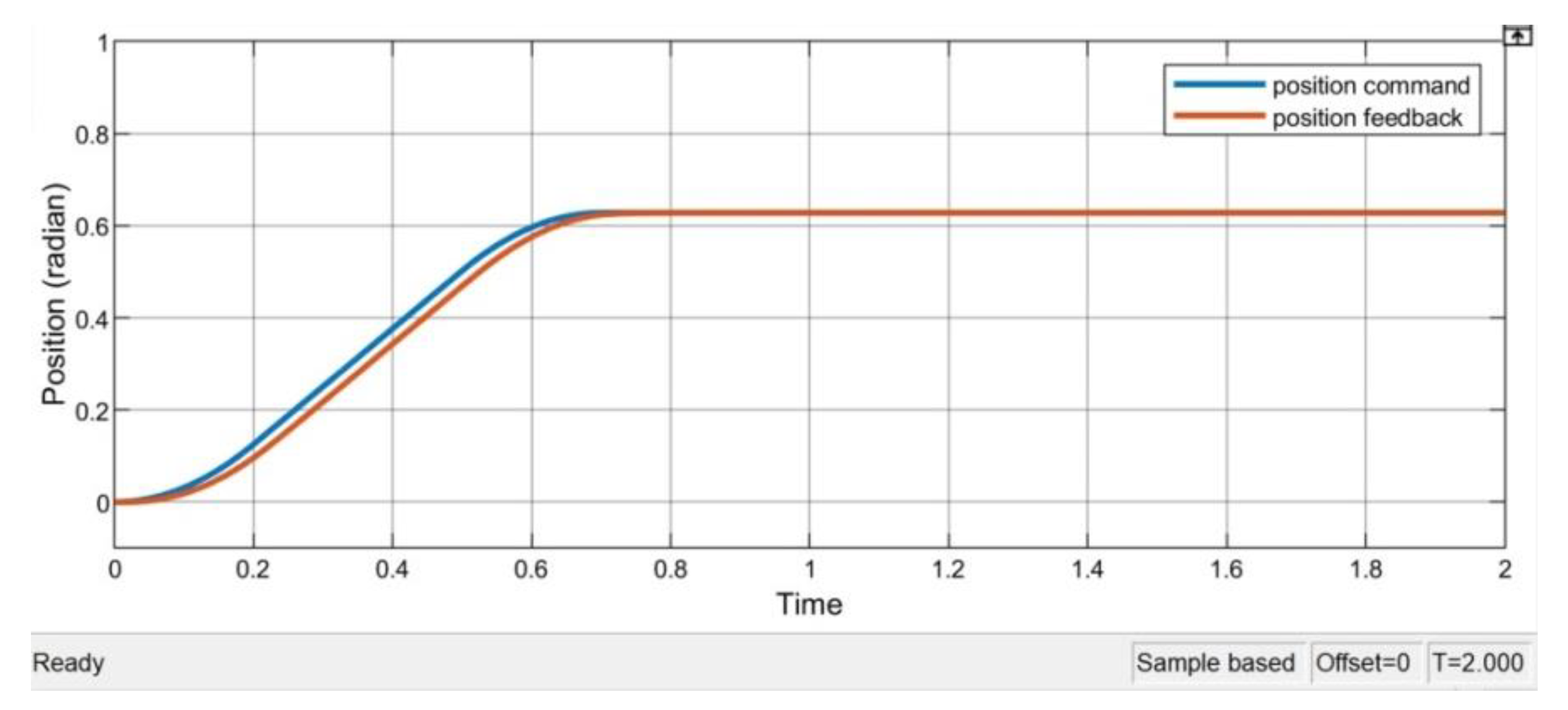
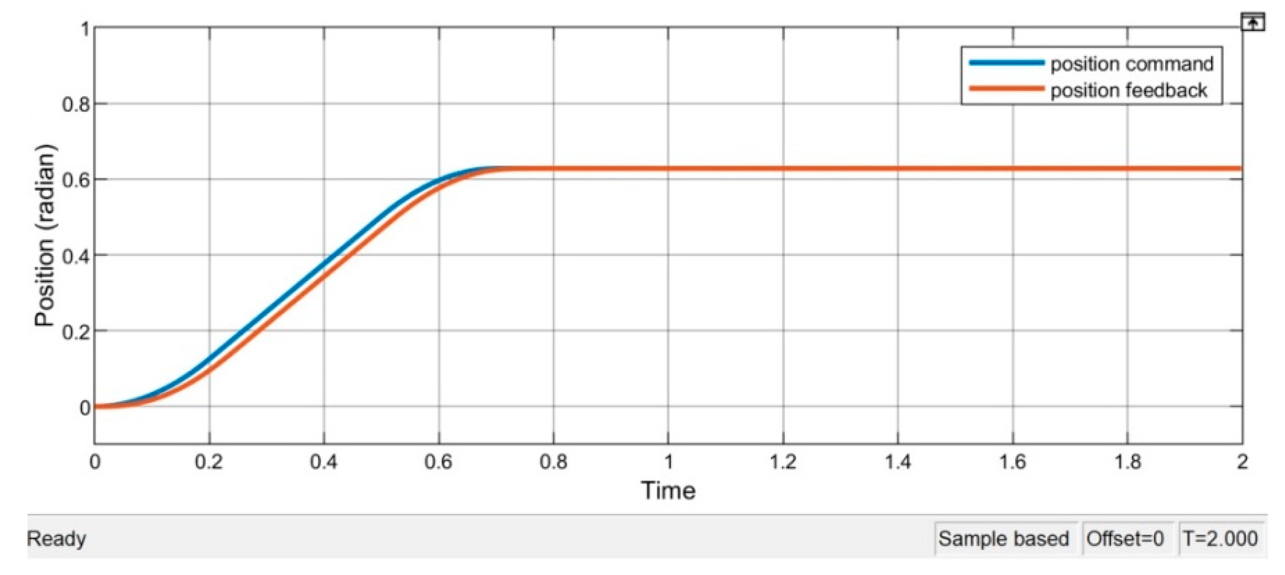
Table 1. Two kinds of command are assumed: (a) position step input, (b) motion control with trapezoidal speed profile limitation. The step input command is 0.628 radian. The motion command includes the acceleration segment, deceleration segment and constant speed, and total angular displacement 0.628 radian in the duration time 0.7 s. Substituting the parameters shown in
Table 1 into (22), the control gain
is chosen such that the resulting second-order system (23) possesses the performances of damping ratio 0.707 and rising time 0.05 s. Thus, the linear control law
and sliding surface
are determined as:
and
According to (28) and (29), and with the setting,
where
and
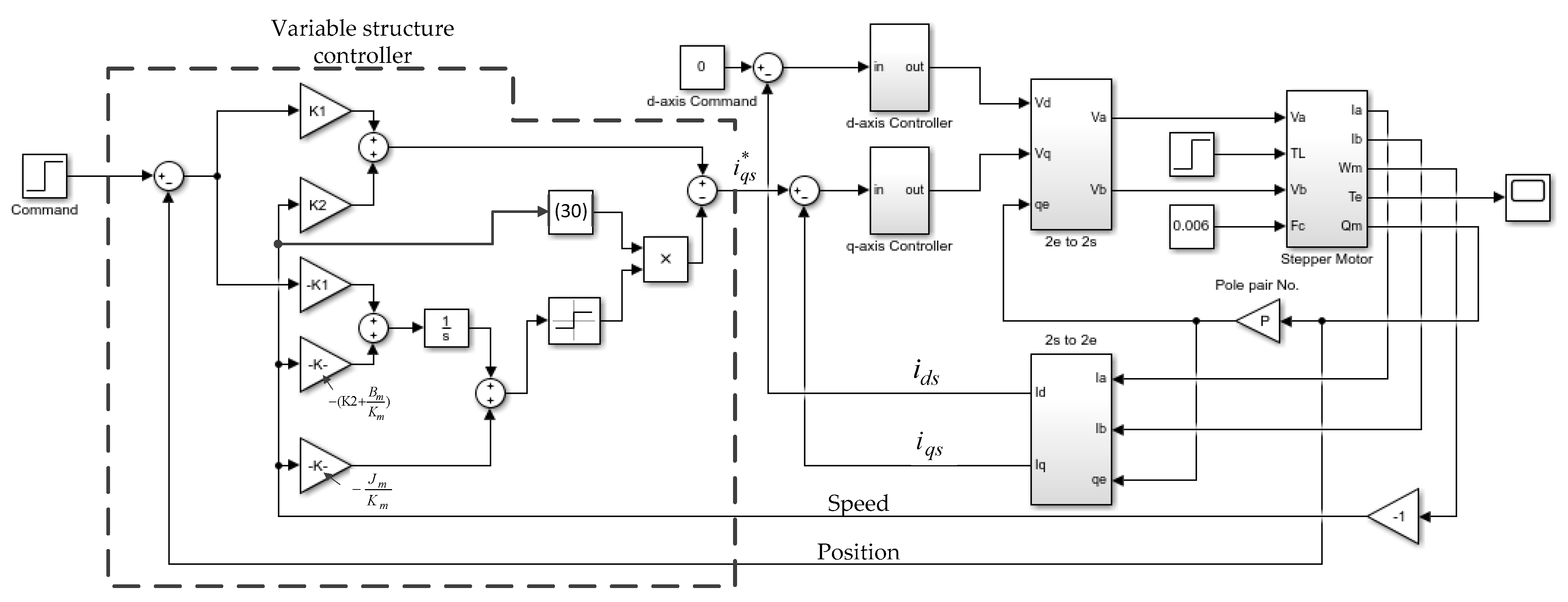
are two positive constants for the VSC control part. The schematic block diagram of the Simulink model of the variable structure controller and the structure of the drive system are shown in
Figure 3.
The system shown in
Figure 3 includes the linear state feedback and variable structure control for the position/speed loops, and the inner d- and q-axis current control loops are dominated by two PI controllers. As shown in
Figure 3, the command of q-axis current control loop is from the output of the variable structure controller, and the command of the d-axis current control loop is set as 0. The sampling time for the current and speed/position control loops are set as 0.05 ms and 0.5 ms, respectively.
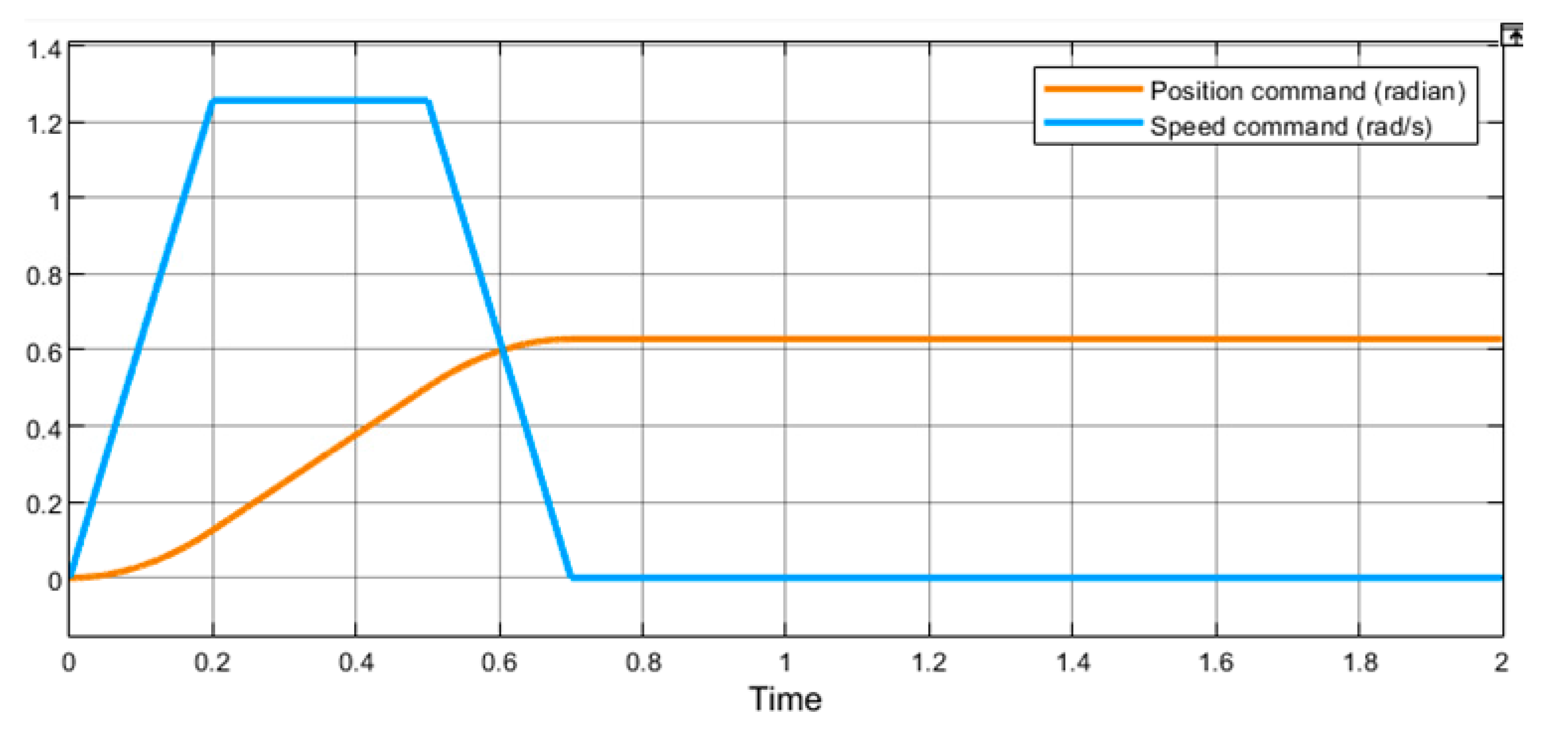
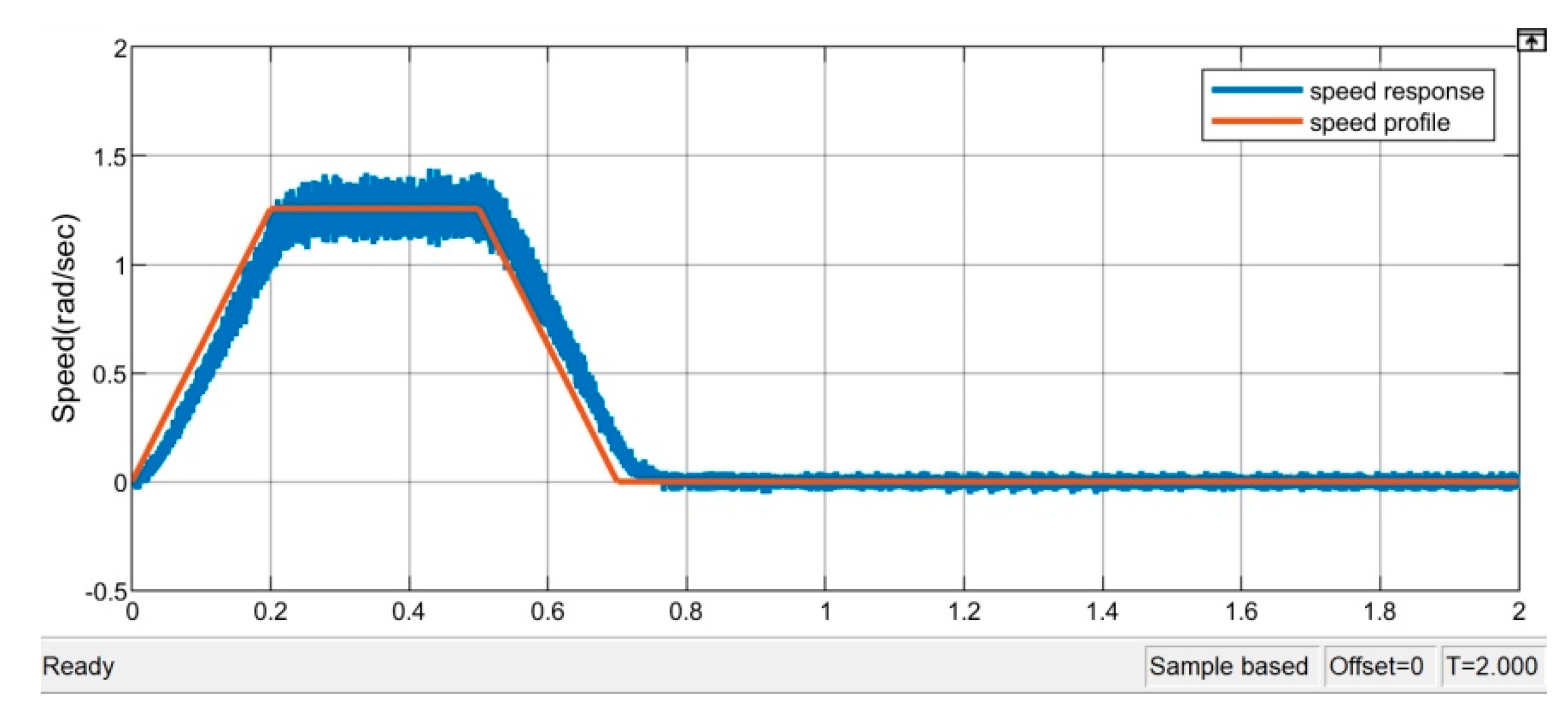
A typical trapezoidal speed profile with a displacement 0.628 radian, as shown in
Figure 4, is used as the command input. The following simulated responses, including the position, speed, current and sliding surface
, will be shown for with and without load conditions, which are defined dependent on whether or not the disk load axis connected. The speed profile of
Figure 4 is made with the time constraints of acceleration period 0.2 s, constant speed period 0.3 s and deceleration period 0.2 s, and the variable structure control part (29) is set as:
In (31), is mainly used to reduce the steady-state error coming from the dead-band, backlash, cogging torque, or other nonlinear part of the system, and make the sliding condition exist. The second part of (31), whereby magnitude is proportional to the motor speed, is designed to guarantee the system states follow the desired trajectory defined in matrix .
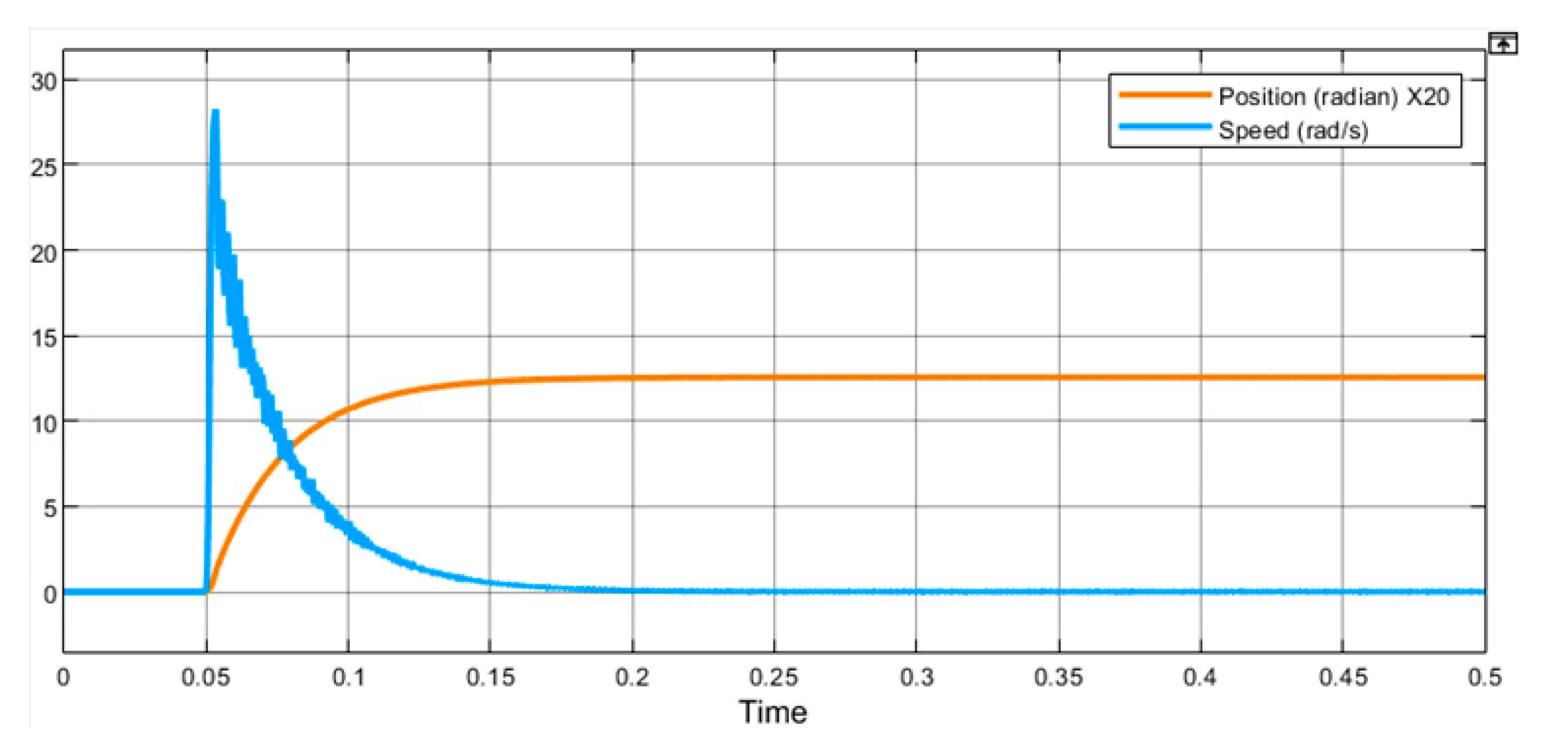
First, the responses of step position command input are shown in
Figure 5. There is no speed restriction on the response, and the speed and position are controlled by the equivalent system matrix
.
Figure 6,
Figure 7 and
Figure 8 are the position, speed and current response under the no-load condition. In
Figure 6, we can see that the feedback has reached the target position of 0.628 radians at the time of about 0.7 s. The simulation shows that the drive system with variable structure control can ensure the performance of the position control. The speed response displayed on
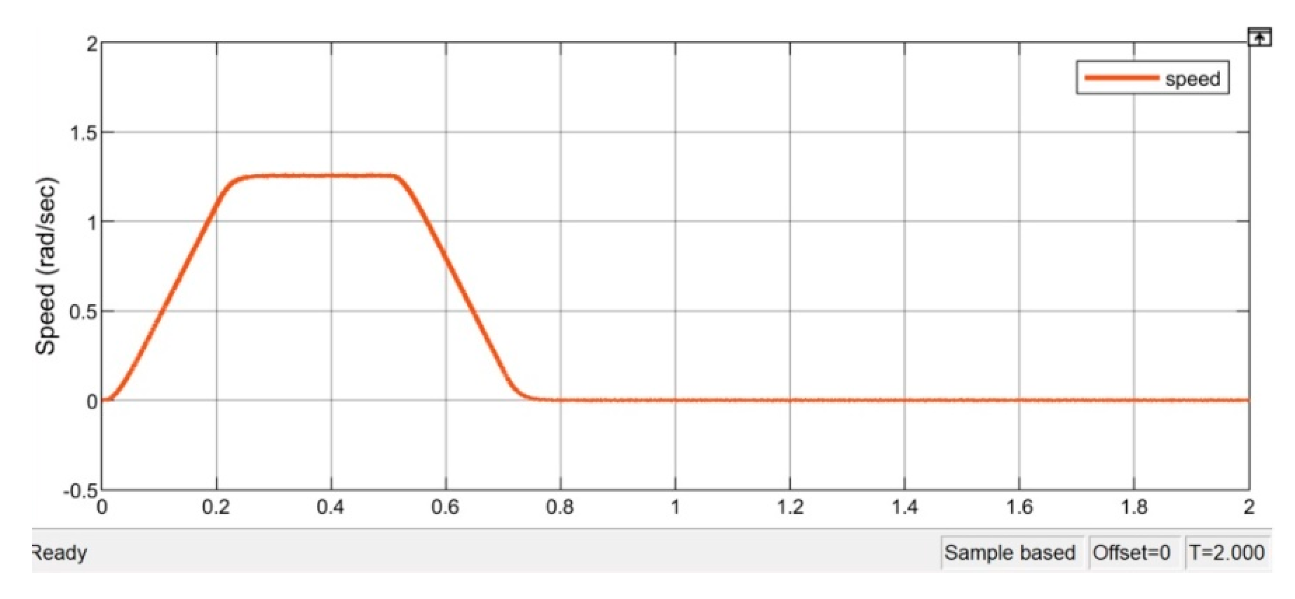
Figure 7 shows that the acceleration segment, constant speed and deceleration are near to the desired speed command profile. From
Figure 7, the speed at the run segment is about 1.256 rad/s. Due to the chatter control of VSC and the low-speed operation, there is a little ripple in the speed response. The current response is shown in
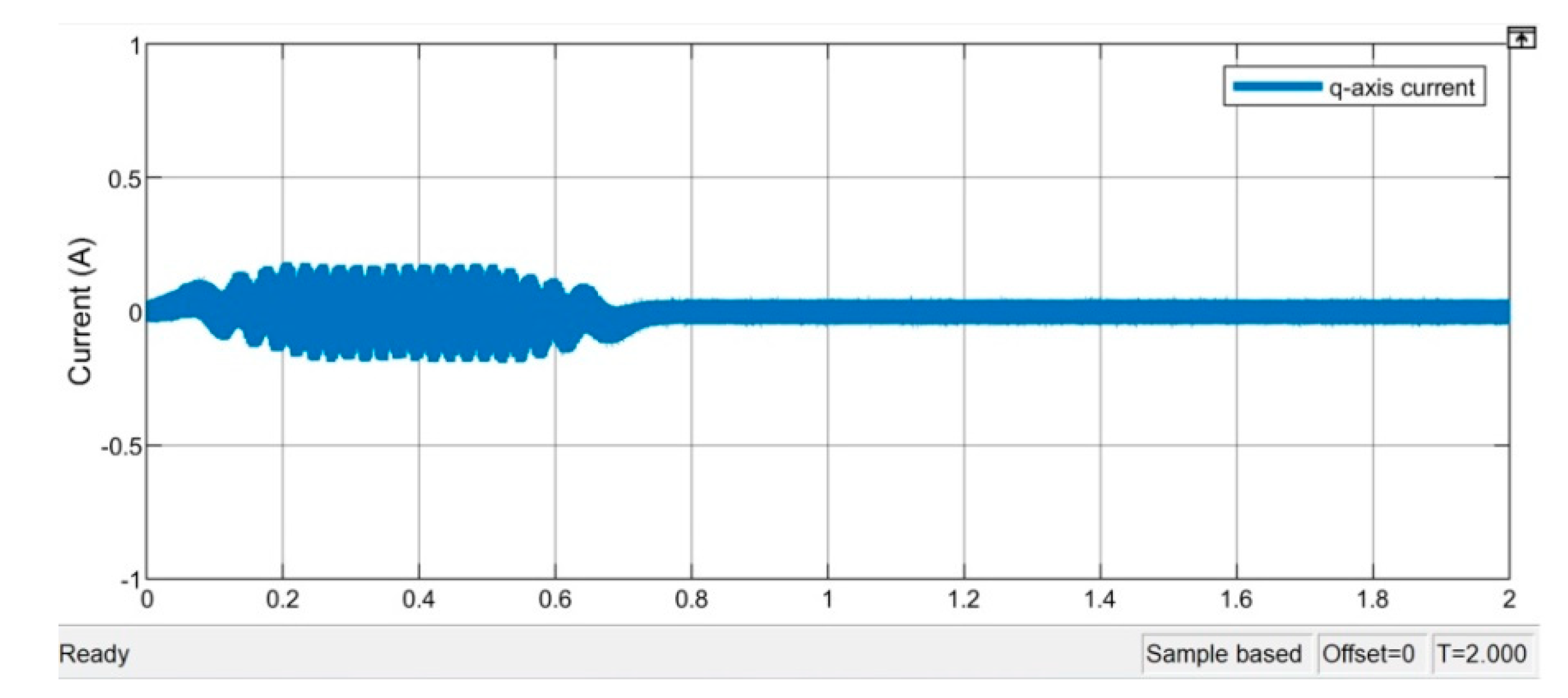
Figure 8, in which the magnitude is small because a no-load condition is asserted.
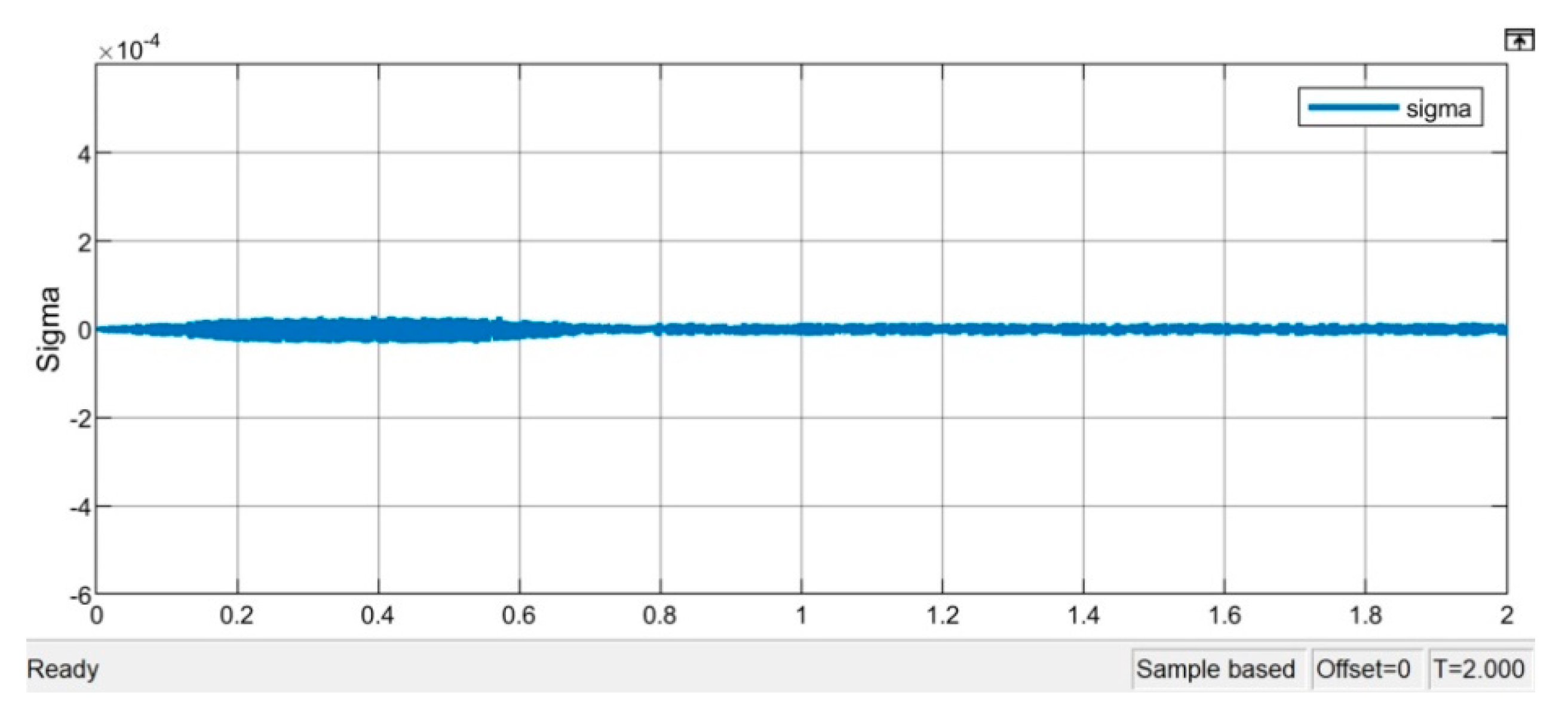
Figure 9 is the response of the sliding surface
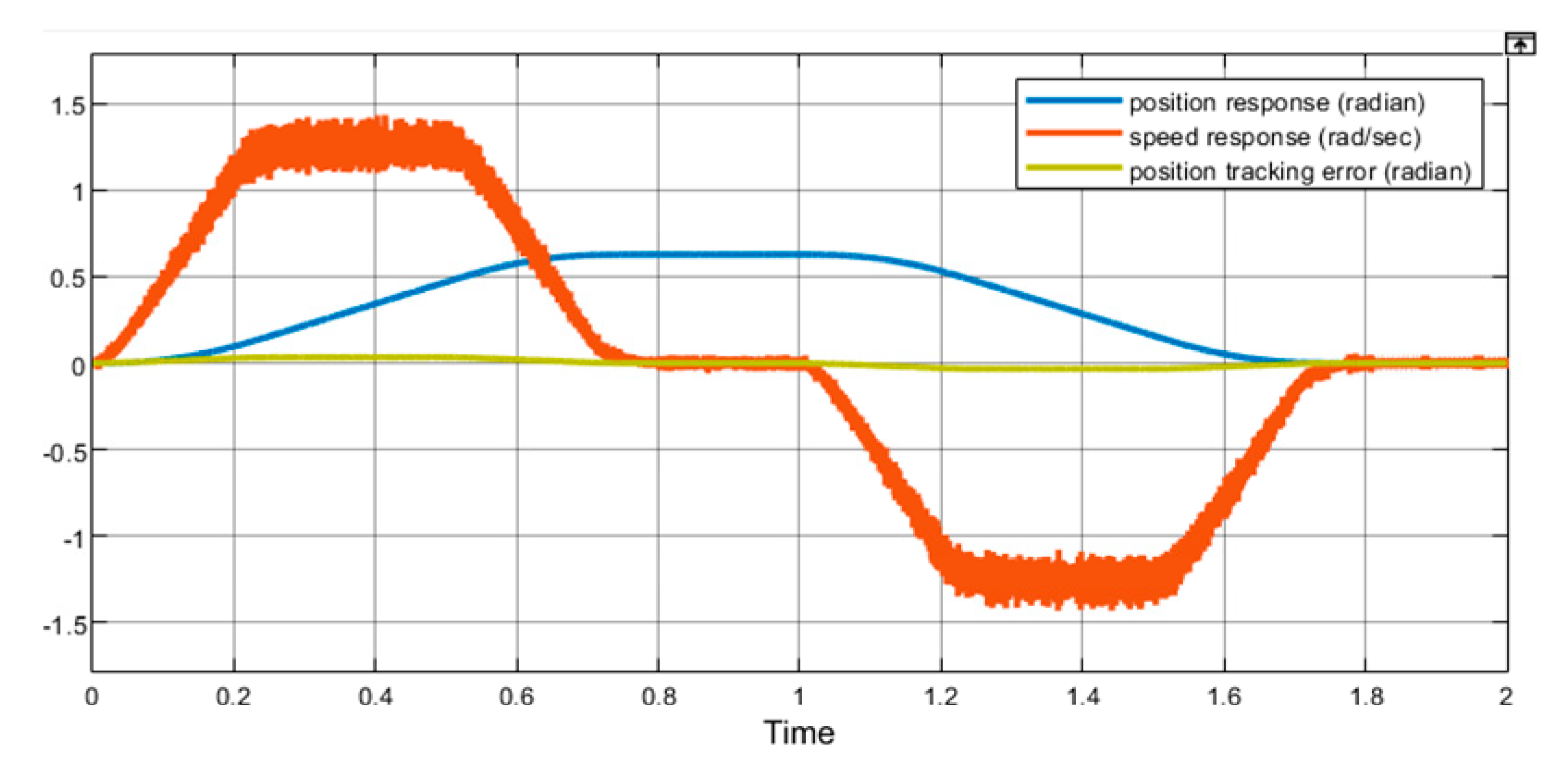
, which shows that the system enters the sliding surface once the motor starts, and it can be used to verify the correctness of the proposed variable structure control. Sometimes, the motion control is shown running forward and backward, as
Figure 10 displays. In it, the position tracking error is defined as the difference between position command and position feedback. Next, the simulation under the load condition is shown; the command used is the same as the no-load condition. For this condition, the inertia and the friction of the rotor are assumed by 10 times and twice the origin, respectively. The simulated results are shown in
Figure 11,
Figure 12 and
Figure 13.
Figure 11,
Figure 12 and
Figure 13 are the position, speed and current responses with load. The position response in
Figure 11 is almost the same as the response without load of
Figure 6; that is what the VSC control wants. However, because the connected flywheel load makes the system with 10 times the inertia as compared to the unload condition, which reduces the system bandwidth and presents small speed ripples. Since the control law of VSC part is used to make sure the system states keep the sliding condition, it is looking forward to a larger q-axis current for load condition. However, since the system has the same setting for both the unload and load conditions, the current response is nearly the same for both cases, as
Figure 8 and
Figure 13 have shown. Next,
Figure 14 displays the response of
with load. As the speed ripple of
Figure 12 is smaller than
Figure 7, the ripple of
in
Figure 14 is smaller than
Figure 9, and the system also stays on the sliding phase from the beginning.
5. Experimental Setup and Results
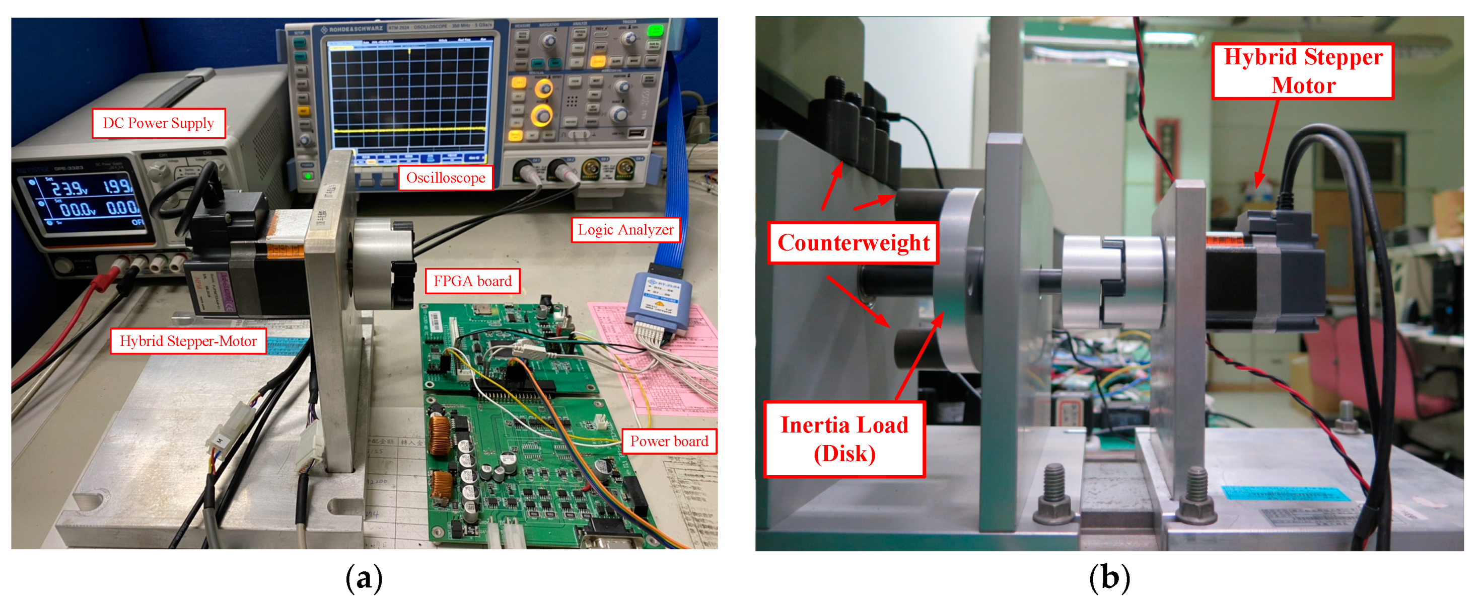
To practically evaluate the actual performance of the proposed control scheme, the experimental setup is shown in
Figure 15a, which includes the FPGA board, power board, DC power supply, hybrid stepper motor, motor load and digital oscilloscope with logic analyzer. On the FPGA board, it includes the Altera Cyclone III FPGA with type EP3C16E144C8N, 12-bit serial analog to digital converter (ADC) AD7866 made by Analog Devices and 12-bit digital to analog converter (DAC) TLV5618 made by Texas Instruments. In the power board, there are two H-bridge circuits used to transfer the DC power to the stepper motor, and two Hall current sensors are set to detect the motor stator currents. The EP3C16E144C8N chip has 84 I/O pins, 15,408 logic elements, 516,096 bits RAM, 56 18 × 18 multipliers and 4 PLLs [
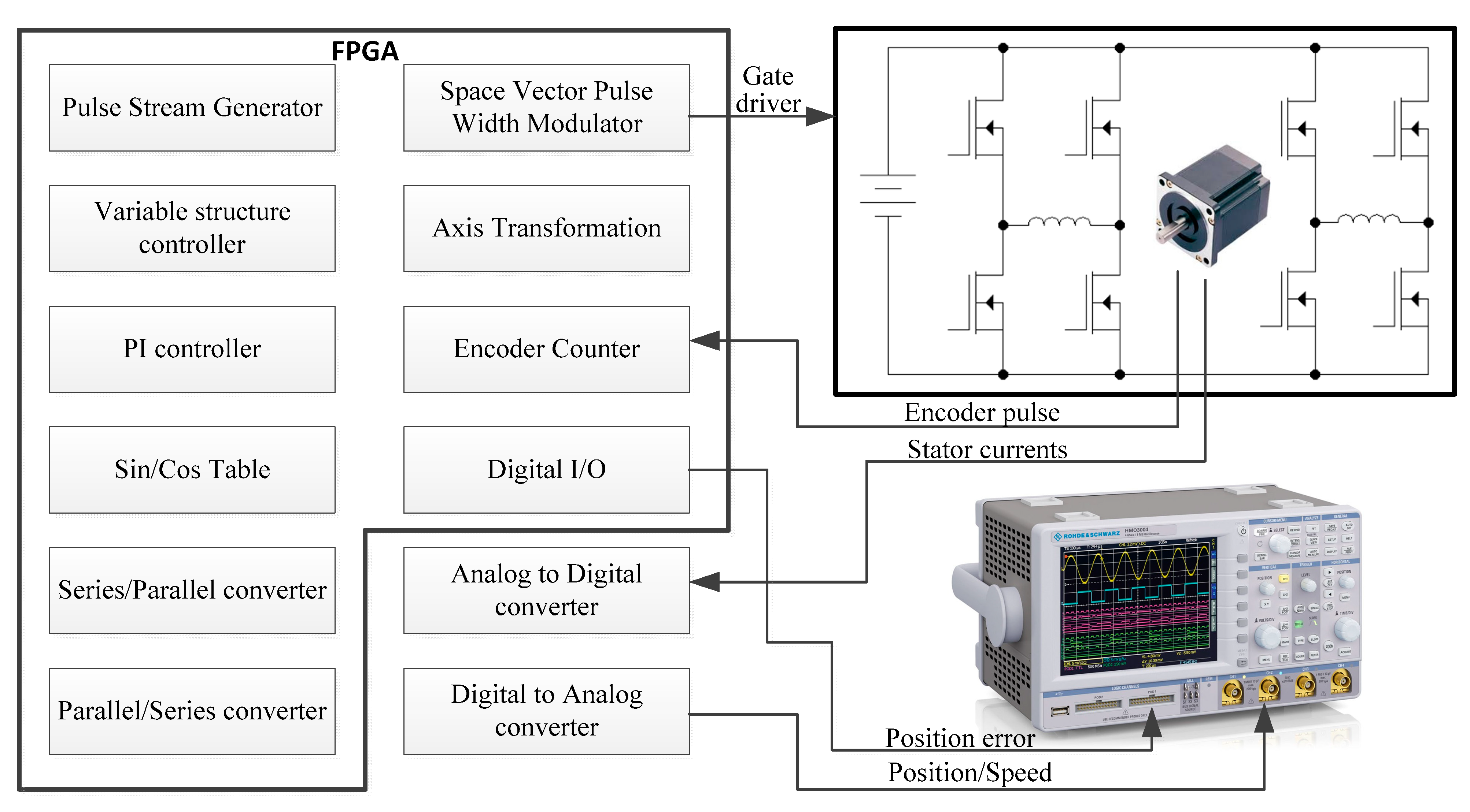
21], and is clocked by 20 MHz. The FPGA chip is used to develop the hardware control system, which includes the coordinate transformation, variable structure controller, PI controllers, 4X quadrature encoder counter, two-phase SVPWM, and the series/parallel conversions for the ADC and DAC converters. A non-optimized usage report about the proposed drive system is shown in
Table 2. ADC and DAC are serial type 12-bit converters clocked by 20 MHz. ADC is used to obtain the analog current of phases A and B detected by Hall sensors, and works with a 20 kHz trigger signal. DAC is used to output the corresponding analog voltage signals of the controlled variables such as the rotor position, speed, and sliding surface
to be checked and compared, and those signals are shown on the digital oscilloscope. DAC is worked with a 2 kHz trigger signal since it is used to demonstrate the mechanic signals. The sampling times for the current control loop and position/speed control loops are, respectively, 0.05 ms and 0.5 ms. The built functions of the FPGA chip and the signal flow diagram out of the FPGA of the experimental system are shown in
Figure 16, and signal flow of the blocks inside the FPGA can be found in
Figure 3. Logic analyzer, which is built in the digital oscilloscope, is used to capture and display the digital signal outputs from the FPGA. In here, the logical analyzer is used to display the position tracking error of the position control loop. The stepper motor is a hybrid one with 50 rotor teeth, rated current 2 A, and is powered by DC bus voltage 24 V. Additionally, it is equipped with a 5000 p/rev incremental encoder for the position/speed feedback. The load system for the experiment is shown in
Figure 15b; it is a flywheel-type load, and counterweights can be used to change the inertia on the rotor. For the comparison purpose, the desired speed waveform and angular destination of the experimental system are the same as the simulated system.
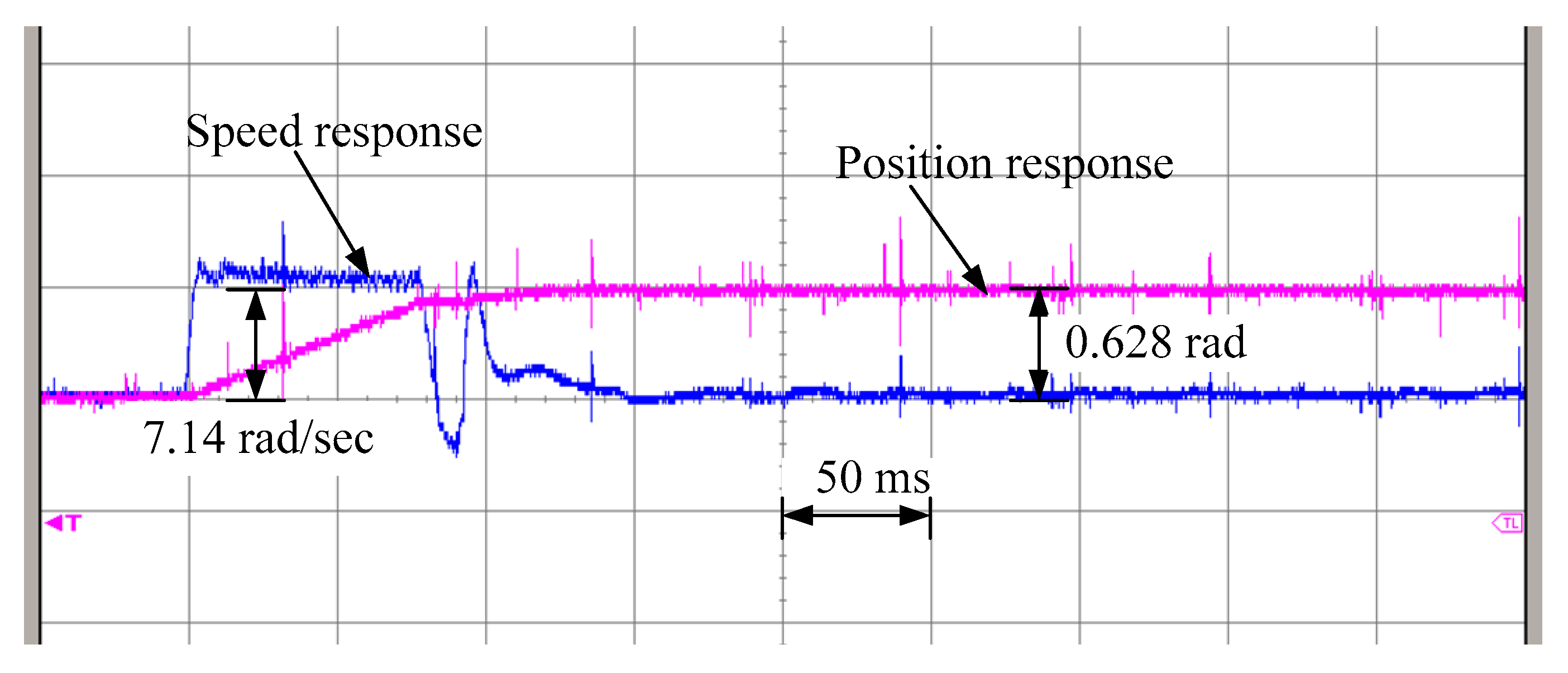
The experimental results with step position command input are shown in
Figure 17. The system takes about 100 ms to reach its steady-state value as simulated, and the speed response is not so sharp as the simulation.
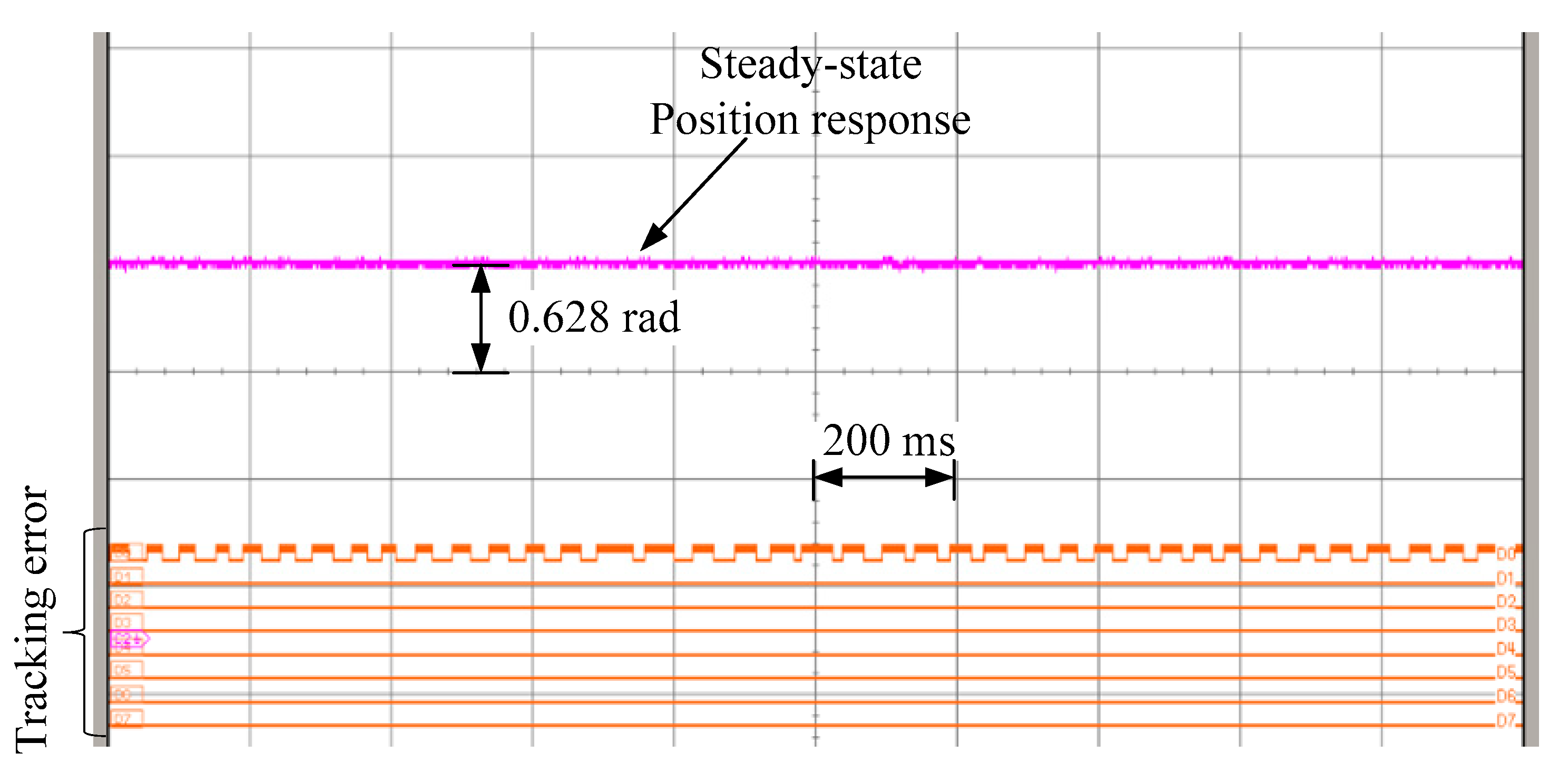
Figure 18 gives the position and speed responses with the 0.628 radian position command. The time base of
Figure 18 is 200 ms/DIV. According to the description about the pulse generator, the amounts of total generated pulse are 2000 within the duration [0 s, 0.7 s]. For the position and speed responses, they fit the requirements about the position and speed constraints. To check the position response precisely, we sent the position error in digital format with 8 bits to the output port of the FPGA, and captured them by the logic analyzer. In
Figure 18, it displays that the bit D0 is switching between 0 and 1, and the other bits, D1-D7, stay at 0. Thus, the position error in the steady-state condition is about one encoder pulse.
Figure 19 is the zoomed plot to the steady-state condition.
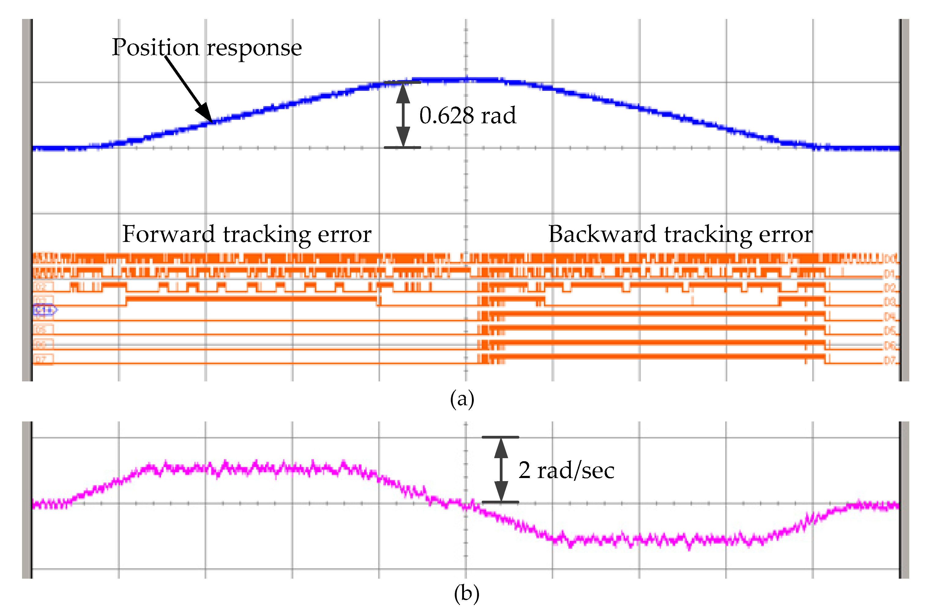
Figure 20 is the result with running forward and backward.
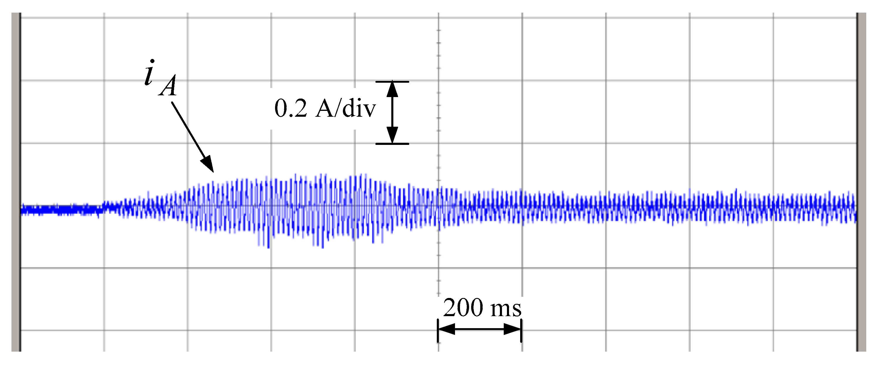
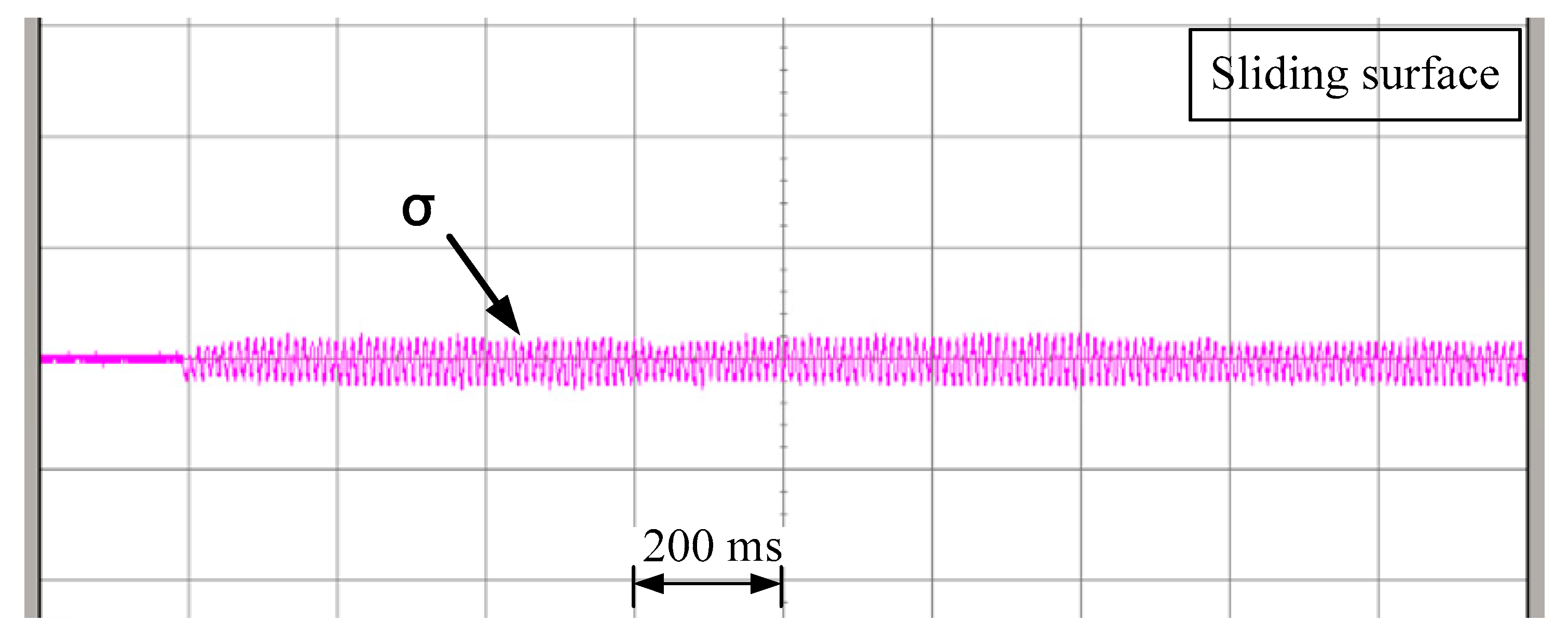
Figure 21 and
Figure 22 are, respectively, the stator current and sliding surface
. Since the system is with a trapezoidal velocity profile command input, the current response is requested to respond to the similar profile as the speed response. In
Figure 22, the sliding surface is always kept at a quite low value since the system enters the sliding phase from starting.
Next, we are going to display the test with load. The motor is connected to a disk load, as shown in
Figure 15b, and four counterweights are added to increase the rotor inertia to about 10 times the case without them, and two-time frictions are assumed.
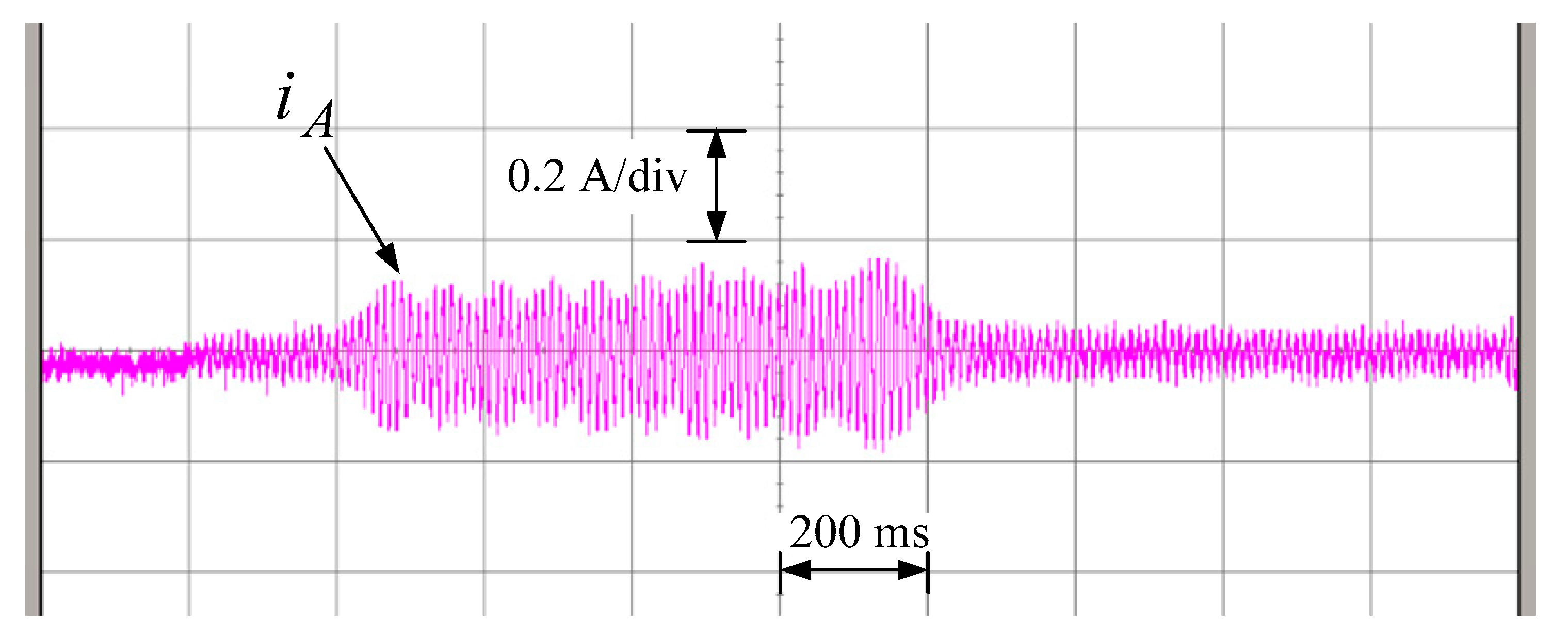
Figure 23,
Figure 24 and
Figure 25 are the results of load conditions.
Figure 23 shows the position and speed responses under the load condition. The speed response is obedient to follow the speed profile as the no-load condition. Since the tested load is constructed by increasing the rotor inertia and friction, more generated torque is needed to overcome the variations as the evidence that the stator current was increased to about 0.35A peak to peak value as shown in
Figure 24, and its magnitude is greater than the one without load connected. Comparing the two sliding surface responses of
Figure 22 and
Figure 25, they show that the ripple of the load condition is greater than the case without load. On the contrary, in the steady-state duration, the system speed is almost zero, and the increased inertia and friction lead to the reduction of system bandwidth. Thus, the magnitude of the ripple about
for the load condition is smaller than the unload condition at the steady-state duration. It can also be seen from the steady-state digital tracking error where the load condition is not so active compared to the no-load condition.
