Abstract
Microfluidic devices providing an accurate delivery of fluids at required rates are of considerable interest, especially for the biomedical field. The progress is limited by the lack of micropumps, which are compact, have high performance, and are compatible with standard microfabrication. This paper describes a micropump based on a new driving principle. The pump contains three membrane actuators operating peristaltically. The actuators are driven by nanobubbles of hydrogen and oxygen, which are generated in the chamber by a series of short voltage pulses of alternating polarity applied to the electrodes. This process guaranties the response time of the actuators to be much shorter than that of any other electrochemical device. The main part of the pump has a size of about 3 mm, which is an order of magnitude smaller in comparison with conventional micropumps. The pump is fabricated in glass and silicon wafers using standard cleanroom processes. The channels are formed in SU-8 photoresist and the membrane is made of SiNx. The channels are sealed by two processes of bonding between SU-8 and SiNx. Functionality of the channels and membranes is demonstrated. A defect of electrodes related to the lift-off fabrication procedure did not allow a demonstration of the pumping process although a flow rate of 1.5 µL/min and dosage accuracy of 0.25 nL are expected. The working characteristics of the pump make it attractive for the use in portable drug delivery systems, but the fabrication technology must be improved.
1. Introduction
In recent decades, a lot of research has been directed towards microfluidic systems. These systems operate with small amounts of fluid using channels from several microns to several hundreds of microns in size. Microfluidic devices are widely implemented in biology and medicine to diagnose bacteria and viruses [1,2], for gene and cell investigations [3,4], and for the synthesis of biological tissues [5,6]. Promising microfluidic devices are small modules that deliver drugs to the human body [7,8]. The module is attached to the body and injects a medicine (for example, insulin) by manual touch [9] or automatically [10], so one does not have to visit a hospital to receive an injection. It is especially convenient when the drug needs to be delivered by small doses in short intervals. Implantable modules that deliver the drug directly to target organ or tissue are of particular interest [11,12]. They significantly increase the therapy effect since the medicine does not have to overcome the physiological barriers of the body.
The simplest drug delivery module consists of a medicine container, pump, and needle [13]. The pump creates an overpressure in the reservoir, the drug is pushed through the needle and enters the body. The module should be small, consume low power, provide high dosage accuracy, and be made of biocompatible materials. The performance of the device is mainly determined by the pump. Several working principles are used for micropump as described in recent reviews [14,15]. Osmotic pumps [16,17,18] are compact, easy to fabricate, and do not require external energy source, but provide a small and unregulated flow rate. Spring-loaded pumps [19,20] also need no battery, but they are not suitable for batch fabrication due to the manual assembly. Thermal actuators [21,22,23] provide a simple and biocompatible design. However, they are notoriously slow and consume a lot of power. A significant progress is achieved in piezoelectric pumps [24,25,26]. They demonstrate a fast response, high pressure, and accurate dosage but have a large size, high driving voltage, and poor compatibility with microtechnology. Other promising candidates for the use in microfluidic systems are electrochemical actuators [27,28,29,30] due to a simple design, compatibility with the microfabrication, and integration with other microfluidic components. However, their size is even larger, and the response time is very long. The flow rate decreases quickly when the pump size is reduced. Therefore, despite the variety of available designs, there is a lack of compact, energy-efficient, and microtechnology-compatible pumps. The improvement of conventional devices has practically reached its limit, and further progress requires unusual approaches.
Recently, an actuator of a new type was demonstrated [31]. It is based on the alternating polarity (AP) electrolysis performed by short voltage pulses. The device consists of a working chamber with two electrodes inside. The chamber is covered by a flexible membrane and filled with an electrolyte. One of the electrodes is grounded, while a series of AP pulses is applied to the working electrode. Bubbles containing H2 and O2 gases are generated above both electrodes. A short duration of pulses (1–5 µs) makes the bubble size smaller than 100 nm [32]. The extra pressure created in the chamber moves the membrane up. Due to the small size of the chamber (500 µm in diameter and 8 µm in height), the displaced volume is below 1 nl. When the pulses are turned off, the nanobubbles (NBs) merge and recombine quickly. A mixture of gases transforms into water in a few milliseconds due to a spontaneous combustion reaction [33], and the membrane returns to the initial state. A reciprocating membrane movement can be performed at a frequency up to 1 kHz. The device operates several orders of magnitude faster than the conventional electrochemical actuators based on DC electrolysis. These features make the novel actuator attractive for pumping purposes, particularly in precise drug delivery systems.
Here, we propose a micropump based on the fast electrochemical actuator. The design and working principle are described, and the expected performance is estimated. The pump is fabricated using conventional microtechnology. We highlight the fabrication issues and provide the first experimental results.
2. Design of the Pump
The pump is shown schematically in Figure 1a. It contains three actuators formed in a 10 µm thick layer of SU-8 photoresist on a 500 µm thick glass substrate. Each chamber has two electrodes inside. The electrode material is a 500 nm thick conductive layer of aluminum covered with a 200 nm thick titanium layer, which demonstrates very good stability in the AP electrolysis [34]. The chambers are sealed with thin silicon nitride films acting as membranes. Platinum disks with a thickness of 100 nm are formed on the membranes allowing for the optical detection of the membrane movement. Above the actuators there is a channel for the liquid being pumped. It is also formed in a 10 μm thick layer of SU-8. The upper wall of the channel is a silicon substrate (380 µm thick) with inlet and outlet ports to fill the pump with liquid. The channels for the electrolyte and pumped liquid have independent ports and are filled separately.
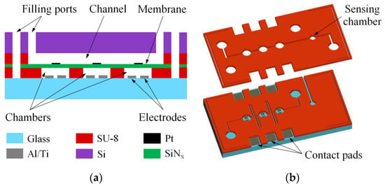
Figure 1.
A schematic illustration of the micropump: (a) a cross-section; (b) a three-dimensional view of the glass substrate with the electrodes and the channels for liquids.
A three-dimensional view of the channels is shown schematically in Figure 1b. The chambers of the actuators have a diameter of 500 µm and are connected to each other by a 50 µm wide channel. The distance between the chambers is 500 µm. The driving voltage applied to one pair of the electrodes can induce the electrochemical process in adjacent chambers. In order to minimize this effect, the channel between the actuators is made in the form of meander to elongate it up to 10 mm. The channel for the pumped liquid is straight and has a width of 100 µm. It contains three chambers with diameters of 500 µm located above the actuators. It is also equipped with an additional chamber of 300 µm in diameter designed to monitor the pressure fluctuations during pumping. The working part of the pump takes a volume of about 3 mm3, which is at least an order of magnitude smaller than the chambers of the diaphragm pumps developed to date [21,22,23,24,25,26,27,28,29,30]. The electrodes have a rectangular shape. Compared to the previously used concentric design, the rectangular electrodes provide more stable long-term operation of the actuator at lower power consumption [35], although the concentric electrodes provide more efficient short-term operation. The width of electrodes is 250 µm and the distance between them is 100 µm.
The electrolyte is separated from the pumped liquid by the membrane layer. In the actuator investigated previously, the membrane was made of polydimethylsiloxane (PDMS) [31]. It exhibited high elasticity and was able to withstand even explosions of microbubbles in the chamber. However, PDMS is a gas permeable material, which may cause leakage of hydrogen and oxygen from the actuator into the upper channel. The gas may form bubbles in pumped liquid and disrupt operation of the pump. In addition, PDMS is difficult to pattern with conventional etching techniques due to its high chemical inertness. Thus, it must be replaced with some other material. An important requirement is a low mechanical stress, which prevents fracture or warping of the membrane. A suitable material is silicon-rich nitride SiNx. Low pressure chemical vapor deposition (LPCVD), under certain conditions, provides SiNx films with low residual stress [36].
The thickness of the SiNx layer determines the membrane deflection and, therefore, the performance of the pump. We have chosen the thickness that provides the same stroke as that achieved earlier for the 30 μm thick PDMS membrane. The deflection of PDMS and SiNx membranes can be predicted and compared using analytical calculations or finite element simulation. However, elastic properties of PDMS vary over a wide range depending on the fabrication conditions [37,38,39]. Thus, the deflection of the PDMS membrane as a function of pressure in the chamber is determined experimentally using an actuator similar to that described in the previous works [31,35]. The chamber is filled with air from a common laboratory line. The overpressure is regulated by a manual valve and detected by a Gems 3300 sensor. The membrane shape is measured with a Polytec MSA-400 laser vibrometer. The deflection at the center as a function of pressure is shown in Figure 2. When driven by the AP electrolysis, the actuator typically provides the stroke below 8 μm. Therefore, the overpressure created by NBs does not exceed 0.1 bar.
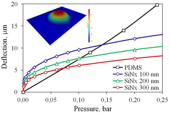
Figure 2.
Membrane deflection as a function of the overpressure in the chamber. The inset shows the PDMS membrane shape measured by the vibrometer.
The deflection of SiNx membranes of various thicknesses from the range of 100–300 nm is calculated by the finite element method using verified software. Strictly speaking, for such a thin membrane the size-dependent effects can influence the mechanical behavior. These effects are related to microstructural phenomena, which are neglected in the classical continuum theory. In order to take them into account, nonlocal strain gradient models are introduced [40,41]. However, a specific scale, for which the size effects become important, remains an open question. The experiments with microfabricated beams demonstrated that the dependence of elastic properties on thickness manifests itself when the thickness goes below 150 nm [42,43,44]. Since the chosen range of the membrane thickness mostly exceeds this value, and for the sake of simplicity, we make the calculations using the classical elasticity theory and bulk material properties of SiNx. The results are shown in Figure 2. At the pressure of 0.1 bar, a 200 nm thick structure provides the deflection similar to that for the PDMS membrane. Therefore, this thickness is chosen for the fabrication. The stress in the membrane reaches 1.9 GPa, which is several times lower than the fracture strength 6.9 GPa of silicon nitride thin films [45]. It was demonstrated that micromechanical structures fabricated from low stress LPCVD SiNx withstand up to 109 loading cycles at the stress amplitude of 5.8 GPa without fatigue-induced degradation or failure [46]. Therefore, the fatigue phenomenon should not limit the performance of the pump.
A separate actuator works as follows. The chamber is filled with sodium sulfate solution that is used as an electrolyte. A series of AP voltage pulses with a frequency of 100 kHz or higher is applied to the electrodes. While the pulses are switched on, the chamber is filled with NBs containing O2 or H2 gases, the pressure increases, and the membrane moves up. It is important that in the AP process only NBs with a size of 60–80 nm [32] are generated but no microbubbles appear. Since the volume of the chamber is small, the concentration of NBs can reach a value as high as 1015 cm−3 in a time as short as 10 ms.
The main problem of the electrochemical actuators using DC electrolysis is a very slow reaction between gases [29] when the voltage is off. Even the use of Pt catalyst with well-developed surface results in a response time of minutes [29] but not milliseconds. The AP process solves this problem in an unexpected way: in NBs containing mixture of O2 or H2 gases the combustion reaction is ignited spontaneously [33]. The mechanism of this combustion is not fully understood, but high surface-to-volume ratio for NBs plays the critical role (see a recent review [47]).
After switching the pulses off the pressure in the chamber decreases fast because when two bubbles containing different gases meet, they merge due to diffusive gas exchange and disappear in 10 ns in the combustion reaction. However, when two bubbles with the same gas meet, the gas exchange is strongly suppressed (no concentration gradient). In this case the repulsion between bubbles induced by the surface charges dominates [47]. Fast extinction of the gas in the chamber strongly reduces the response time of the actuator. Thus, the gas generation in the form of NBs has a principal significance for the short response time of the actuator.
In the pump the fluid is pumped due to the peristaltic movement of the actuators. Peristalsis is a simple and reliable pumping method that is widely implemented in microfluidics using actuators of various types [48,49,50,51,52]. The actuators operate in the sequence shown in Figure 3a. They create a peristaltic wave and push the liquid from left to right. The pumping cycle consists of six phases. In each phase, at least one membrane is lifted, preventing the back flow. This sequence is set by the driving signals shown in Figure 3b. A series of AP voltage pulses with a frequency f~100 kHz is applied to each actuator during the active time ta. The membrane rises and displaces the liquid. During the passive time tp, the pulses are switched off and the membrane returns to its initial position. The signals have the same shape for all the actuators, but for the middle and right devices it is shifted by 2ta/3 and 4ta/3, respectively.
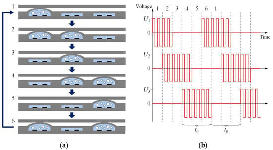
Figure 3.
Working principle of the micropump. The image (a) illustrates sequential operation of the actuators. The liquid is pushed from left to right. The driving signals are schematically illustrated in panel (b). The AP voltage pulses are applied to each actuator during the active time ta. The numbers at the top indicate the pumping phases.
For proper operation, the passive time should be long enough to return the membrane to the initial position. This process takes 40–60 ms for complete return to the initial state [35]. Since in the 6-phase cycle the active and passive times are equal, one can estimate the cycle duration as tc = ta + tp ≈ 100 ms, and the working frequency of the pump is fc = 1/tc = 10 Hz. The volume of liquid pumped per cycle is equal to half of the volume displaced by the membrane:
where r = 250 µm is the chamber radius and d is the deflection of the membrane in its center. Assuming that the membrane rises to a moderate level d = 5 µm, we obtain the displaced volume ΔV = 0.25 nL. The conventional pumps have a stroke volume of several tens or hundreds of nanoliters [21,25,26]. Therefore, the proposed device demonstrates a significant improvement in the dosage precision. The flow rate is calculated as R = ΔVfc = 0.15 µL/min. This value is small in comparison with R~10 µL/min provided by other devices [22,23,24,25,26,27,28,29,30]. However, the actuator can operate with a significantly shorter active and passive time ~1 ms [53]. By setting the working frequency at fc = 100 Hz or higher, we can increase the flow rate up to 1.5 µL/min. Thus, the pump is expected to provide a sufficient pumping speed in combination with a high dosage accuracy, which is beneficial for drug delivery systems.
It is worth noting that the spontaneous combustion of hydrogen and oxygen in NBs produces heat as normal combustion would do. A significant heating of the electrolyte has been observed for the case when the electrodes were deposited on a membrane with a small thermal mass [54]. However, when the electrodes were fabricated on a bulk substrate, the temperature rise was smaller than 1 °C [33]. It is explained by a large thermal mass of the substrate, which is able to absorb the heat produced in a small chamber. Therefore, significant heating of the pump during operation is not expected.
3. Fabrication
The fabrication procedure is shown in Figure 4. It requires six photomasks for the UV contact lithography and three 100 mm diameter wafers. The process begins with the formation of the electrodes, signal lines and contact pads on a 500 µm thick MEMpax glass wafer (wafer 1) using the lift-off technique (Figure 4a). For this purpose, a 1.7 µm thick mold of the photoresist OIR 907-17 is applied by spin-coating, exposed and developed. A 10 nm thick titanium adhesive layer is deposited by e-beam evaporation followed by the deposition of a two-layer Al/Ti film with a thickness of 500/200 nm. The rest of the photoresist is washed out with acetone and isopropanol. The two-layer structure results in a 2 Ω resistance between the electrode and contact pad. Further, the channels for electrolyte are formed in a 10 µm thick layer of photoresist SU-8 25 (Figure 4b). The soft bake and post exposure bake are carried out at 95 and 80 °C during 20 and 10 min, respectively. The hard bake in not performed in order to eliminate final cross-linking of the resist, and to keep the surface compliant for further bonding process.
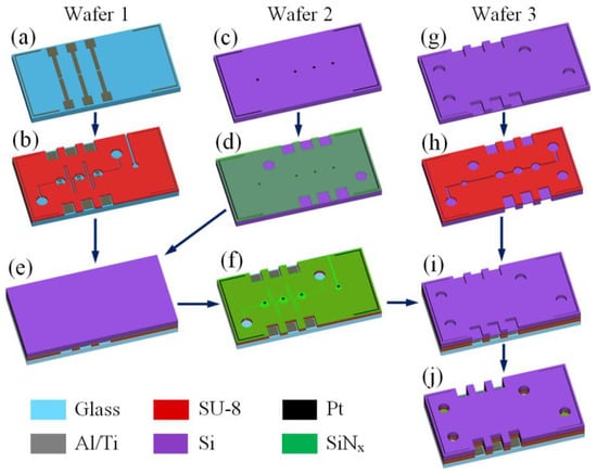
Figure 4.
Fabrication procedure of the pump: (a) patterning of the Al/Ti electrodes on the glass wafer; (b) formation of the channels for the electrolyte in the SU-8 layer; (c) patterning of Pt disks on the Si wafer; (d) deposition and patterning of the SiNx film; (e) bonding of SiNx to SU-8; (f) complete plasma etching of the Si wafer; (g) partial plasma etching of the holes in the Si wafer; (h) formation of the channels for the pumped liquid in the SU-8 layer on the opposite side; (i) bonding of SU-8 to SiNx; (j) final etching of the holes.
At the next stage, a 380 μm thick double side polished silicon wafer (wafer 2) is processed. Platinum discs with a thickness of 100 nm are formed at the polished surface by magnetron sputtering and lift-off (Figure 4c). Next, a membrane layer of 200 nm thick low stress silicon-rich nitride is deposited by LPCVD and patterned by reactive ion etching (RIE, Figure 4d). Further, the wafer is flipped over and bonded to wafer 1 (Figure 4e). The bonding between SiNx and SU-8 is performed using the anodic bonding system EVG510. The wafers are heated up to 180 °C and pressed together with a force of 2 kN during 60 min. The silicon is completely removed from the bonded stack by RIE in SF6 plasma, leaving the SiNx film on top of the SU-8 layer (Figure 4f).
The second silicon wafer (wafer 3) has a thickness of 380 μm and is polished at both sides. First, the inlet and outlet holes and openings for contact pads are etched (Figure 4g). The BOSCH process is performed through the mask of 300 nm thick SiO2 and 3.5 μm thick photoresist OIR 908-35. At this step the wafer is etched to a depth of about 330 μm, in order to form the channels for the pumped liquid in a 10 µm thick SU-8 25 layer on the opposite side (Figure 4h). After the exposure and development of SU-8, the wafer is bonded to the glass wafer (Figure 4i). The surfaces of SiNx and SU-8 are linked using the method described above. Then the holes are finally etched by the BOSCH process (Figure 4j), the mask is removed by RIE and the glass wafer is cut with a dicing saw.
The fabricated assembly containing six samples is shown in Figure 5a. One can see the dark spot in the central part, where SU-8 is well bonded to SiNx. Typically, this spot covers about half the wafer area. Due to incomplete bonding, only 60% of the samples have hermetically sealed channels. The assembly is divided into separate chips manually. The glass and silicon sides of the chip are shown in Figure 5b,c, respectively. The sample has a sufficiently large size of 28 × 22 mm2 chosen for the convenience of connecting the microfluidic tubes. In addition, it allows one to design the channels long enough to observe the pumping by meniscus movement. Figure 5d shows a close-up view of the actuator. Light spots around the chamber and channels are the areas of poor bonding. For this sample the bonding provides no leakage, and it is strong enough to withstand the pressure above 5 bar in the channels, but the process has to be improved in order to increase the bonding quality and fabrication yield. This can be achieved by optimizing the thermal treatment of SU-8 and bonding conditions.
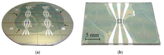
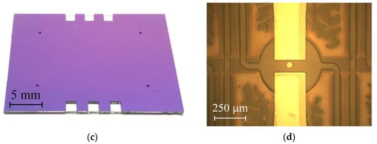
Figure 5.
(a) A photo of the assembled wafers from the glass side. The arrows indicate the edge of the dark spot, where SU-8 is well bonded to SiNx. (b,c) A separate chip detached from the assembly. The photos are taken from the glass and silicon sides, respectively. The black rectangle in image (b) indicates the actuator that is zoomed in panel (d).
4. Testing
To test the pump, a holder is designed and fabricated using a 3D printer. The chip is placed on the lower platform glass side down and pressed by the upper platform using screws, as shown in Figure 6. The lower platform contains six tungsten probes, which are installed on the contact pads of the sample and provide driving signals to the electrodes. In addition, it has an opening to observe the movement of the membranes and the meniscus in the channel. The upper platform has four ports for connecting the microfluidic tubes with the outer diameter of 0.5 mm using nuts and ferrules. The actuators are filled with the electrolyte, which is a molar solution of Na2SO4 in distilled water. The channel for the pumped liquid is filled with distilled water. The holder is installed onto a stage of the microscope equipped with a Moticam 1SP camera. In order to verify the pump for leakage and membrane movability, the pressure is created in the channels using a syringe. The deflection of the membranes under this pressure is detected by the platinum discs coming out of focus of the microscope, as demonstrated in Video S1.
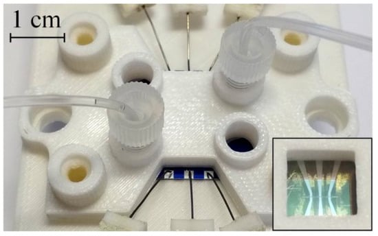
Figure 6.
A micropump mounted in the holder. The probes are connected to the contact pads and the microfluidic tubing is connected to the inlet and outlet ports. The inset shows the bottom side of the holder with a square opening.
The driving voltage is provided by a homemade three-channel signal generator based on the microcontroller STM32G474RBT3. The signal is produced by the microcontroller using a direct digital synthesis method and amplified 20 times by a built-in class AB power amplifier. For each actuator, series of AP voltage pulses are fed to the working electrode, while the counter electrode is grounded. Previously it was shown that the membrane deflection increases, and the degradation of the electrodes slows down with the frequency of pulses f [53]. Here, we take the maximal value f = 500 kHz provided by the generator. The series consists of N = 50,000 pulses with the amplitude Ua. The active time is ta = N/2f = 50 ms and the passive time is chosen to be tp = 50 ms, so the pump operates at the frequency fc = 10 Hz.
The first test of the pump revealed a problem related to the formation of long-lived bubbles in the working chambers of the actuators. Normally in the AP process, no visible bubbles are generated [55] and their unexpected formation indicates the presence of some active defects. The bubbles emerge at the edges of the electrodes and grow until the chamber is filled with gas and the current is blocked. They appear at a voltage Ua = 8 V and grow faster as Ua increases. At an amplitude of 12–14 V, which is typically required to achieve a significant membrane deflection, the chamber is filled with gas in several tens of seconds, see Video S2. At a sufficiently high voltage, short-lived microbubbles are observed, which disappear in a few hundred microseconds due to a spontaneous combustion reaction between hydrogen and oxygen as was observed earlier [31]. This effect shows that together with parasitic gas formation the regular AP electrolysis also occurs.
In order to explain the formation of the long-lived visible bubbles, an additional experiment is performed. The glass substrate with the electrodes is detached from the assembly and placed in a Petri dish filled with the electrolyte. This configuration allows observation of the working surface of the electrodes. The AP pulses with Ua = 10 V are continuously applied to one electrode during 60 s, while the other electrode is grounded. As well as in the pumping regime, the gas production is observed. It is accompanied by the degradation of the electrodes, which visually appears as the darkening of their edges, see Figure 7. After the test, the chemical composition of the sample is investigated with the energy-dispersive X-ray (EDX) spectrometer Oxford Instruments INCA X-act, which is installed into the scanning electron microscope (SEM) Zeiss Supra 40. The maps of chemical elements are shown in Figure 7. The dark region contains less aluminum than the undamaged one, while the titanium content is the same in both areas. In addition, the dark region demonstrates higher content of silicon. It means that X-rays coming from the glass substrate are blocked by the damaged part to a lesser degree compared to the undamaged electrode area. To all appearance, aluminum is removed from under the titanium working layer during the AP electrolysis, and this process is accompanied by the generation of visible bubbles.
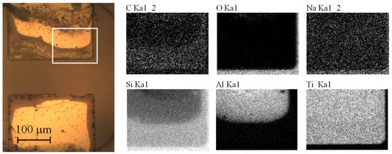
Figure 7.
The electrodes after the test. The bottom electrode was grounded, while the AP voltage pulses with Ua = 10 V were applied to the upper electrode during 60 s. The optical micrograph of the electrodes is shown on the left. The white rectangle indicates the area of EDX analysis. Right images demonstrate the EDX mapping of chemical elements at 30 kV accelerating voltage.
Al/Ti electrodes have been used previously in the fast electrochemical actuators [31,35,53] and in several experiments on the AP electrolysis [32,56,57,58]. They can be recommended as rather durable structures, which are able to withstand extremely high current densities ~100 A/cm2 for long time. The degradation of the electrodes manifested itself as the oxidation of the titanium working layer, but no removal of aluminum was observed. Probably, this phenomenon takes place in the micropump due to a change in the fabrication technology. Previously, the electrodes were patterned by wet etching, but here the lift-off technique is used. The lift-off provides a sharper edge of the film and may cause fence-like structures, which act as preferable sites for the formation of the pinned bubbles during the electrolysis. The defects at the electrode edge are shown in Figure 8. Further, we plan to correct the fabrication procedure in order to avoid gas generation and removal of Al that will allow the investigation of the pump performance in various regimes.
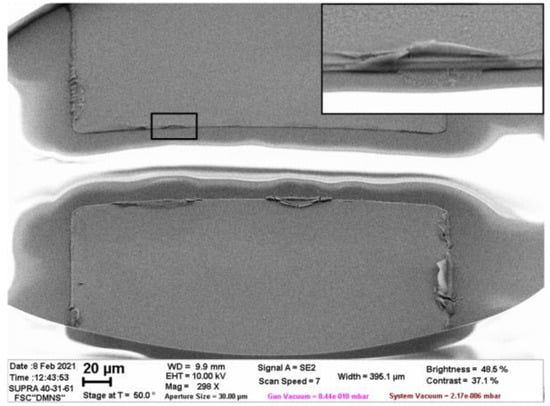
Figure 8.
SEM image of the as-fabricated electrodes captured at an angle of 40° with respect to the substrate plane. The inset demonstrates the fence-like structure at the electrode edge, which is marked by the black frame.
5. Conclusions
A peristaltic micropump using electrochemical generation of nanobubbles as a new working principle is described. It contains three actuators, which are driven by the AP electrolysis performed by microsecond voltage pulses. Such actuators operate several orders of magnitude faster than the conventional electrochemical devices. The pump is designed to be fabricated with standard cleanroom processing. The actuators are formed in the SU-8 photoresist and sealed by the SiNx membrane. The channels for the pumped liquid are also made in SU-8. The fabrication procedure requires one glass wafer, two silicon wafers, and six photomasks. It includes two processes of bonding between SU-8 and SiNx, which are the most critical steps. For reasons of handling convenience, we set a relatively large size of the chip of 28 × 22 mm2, although the working part has a footprint of 3 × 1 mm2. The pump is designed to have a flow rate of 1.5 μL/min with a dosage accuracy of 0.25 nL at a working frequency of 100 Hz, targeting portable drug delivery devices. However, the defect of electrodes resulted in the formation of long-lived parasitic bubbles in the chambers of the actuators, which prevent actual pumping. The growth of these bubbles is accompanied by removal of Al from under the working Ti layer of the electrodes. It was not observed previously when the electrodes were patterned by wet chemical etching, making the lift-off technique a candidate for further investigations towards the hampered performance.
Supplementary Materials
The following are available online at https://www.mdpi.com/2076-0825/10/3/62/s1, Video S1: Deflection of the membranes under the air pressure of about 0.1 bar, which is periodically created in the channel by a syringe. Video S2: Formation of the long-lived visible bubbles in the chambers. The pump is driven by AP voltage pulses with the amplitude of 13 V.
Author Contributions
Conceptualization, I.V.U., V.B.S. and G.J.M.K.; investigation, I.V.U., V.B.S. and P.S.S.; resources, A.E.M. and K.M.; writing—original draft preparation, I.V.U.; writing—review and editing, V.B.S. and G.J.M.K. All authors have read and agreed to the published version of the manuscript.
Funding
I.V.U., P.S.S. and A.E.M. acknowledge support from the Russian Science Foundation, grant number 18-79-10038. K.M., V.B.S. and G.J.M.K. acknowledge support from the Netherlands Organization for Scientific Research (NWO) grant number 13595.
Institutional Review Board Statement
Not applicable.
Informed Consent Statement
Not applicable.
Data Availability Statement
The data presented in this study are available on request from the corresponding author.
Acknowledgments
Authors acknowledge technical support from the Facilities Sharing Centre “Diagnostics of Micro- and Nanostructures”.
Conflicts of Interest
The authors declare no conflict of interest. The funders had no role in the design of the study; in the collection, analyses, or interpretation of data; in the writing of the manuscript, or in the decision to publish the results.
References
- Nasseri, B.; Soleimani, N.; Rabiee, N.; Kalbasi, A.; Karimi, M.; Hamblin, M.R. Point-of-care microfluidic devices for pathogen detection. Biosens. Bioelectron. 2018, 117, 112–128. [Google Scholar] [CrossRef]
- Basiri, A.; Heidari, A.; Nadi, M.F.; Fallahy, M.T.P.; Nezamabadi, S.S.; Sedighi, M.; Saghazadeh, A.; Rezaei, N. Microfluidic devices for detection of RNA viruses. Rev. Med. Virol. 2020, e2154. [Google Scholar] [CrossRef]
- Luo, T.; Fan, L.; Zhu, R.; Sun, D. Microfluidic single-cell manipulation and analysis: Methods and applications. Micromachines 2019, 10, 104. [Google Scholar] [CrossRef]
- Coluccio, M.L.; Perozziello, G.; Malara, N.; Parrotta, E.; Zhang, P.; Gentile, F.; Limongi, T.; Raj, P.M.; Cuda, G.; Candeloro, P.; et al. Microfluidic platforms for cell cultures and investigations. Microelectron. Eng. 2019, 208, 14–28. [Google Scholar] [CrossRef]
- Wang, X.; Liu, J.; Wang, P.; deMello, A.; Feng, L.; Zhu, X.; Wen, W.; Kodzius, R.; Gong, X. Synthesis of biomaterials utilizing microfluidic technology. Genes 2018, 9, 283. [Google Scholar] [CrossRef] [PubMed]
- Ma, J.; Wang, Y.; Liu, J. Biomaterials meet microfluidics: From synthesis technologies to biological applications. Micromachines 2017, 8, 255. [Google Scholar] [CrossRef]
- Riahi, R.; Tamayol, A.; Shaegh, S.A.M.; Ghaemmaghami, A.M.; Dokmeci, M.R.; Khademshosseini, A. Microfluidics for advanced drug delivery systems. Curr. Opin. Chem. Eng. 2015, 7, 101–112. [Google Scholar] [CrossRef] [PubMed]
- Sanjay, S.T.; Zhou, W.; Dou, M.; Tavakoli, H.; Ma, L.; Xu, F.; Li, X. Recent advances of controlled drug delivery using microfluidic platforms. Adv. Drug Deliv. Rev. 2018, 128, 3–28. [Google Scholar] [CrossRef] [PubMed]
- Lo, R.; Li, P.-Y.; Saati, S.; Agrawal, R.N.; Humayun, M.S.; Meng, E. A passive MEMS drug delivery pump for treatment of ocular diseases. Biomed. Microdevices 2009, 11, 959–970. [Google Scholar] [CrossRef]
- Fiering, J.; Mescher, M.J.; Leary Swan, E.E.; Holmboe, M.E.; Murphy, B.A.; Chen, Z.; Peppi, M.; Sewell, W.F.; McKenna, M.J.; Kujawa, S.G.; et al. Local drug delivery with a self-contained, programmable, microfluidic system. Biomed. Microdevices 2009, 11, 571–578. [Google Scholar] [CrossRef]
- Stewart, S.A.; Dominguez-Robles, J.; Donnelly, R.F.; Larraneta, E. Implantable polymeric drug delivery devices: Classification, manufacture, materials, and clinical applications. Polymers 2018, 10, 1379. [Google Scholar] [CrossRef]
- Pons-Faudoa, F.P.; Ballerini, A.; Sakamoto, J.; Grattoni, A. Advanced implantable drug delivery technologies: Transforming the clinical landscape of therapeutics for chronic diseases. Biomed. Microdevices 2019, 21, 47. [Google Scholar] [CrossRef] [PubMed]
- Cobo, A.; Sheybani, R.; Meng, E. MEMS: Enabled drug delivery systems. Adv. Healthc. Mater. 2015, 4, 969–982. [Google Scholar] [CrossRef] [PubMed]
- Mendoza, L.A.V.; Scilletta, N.A.; Bellino, M.G.; Desimone, M.F.; Catalano, P.N. Recent advances in micro-electro-mechanical devices for controlled drug release applications. Front. Bioeng. Biotechnol. 2020, 8, 827. [Google Scholar] [CrossRef] [PubMed]
- Ghazali, F.A.M.; Hasan, M.N.; Rehman, T.; Nafea, M.; Ali, M.S.M.; Takahata, K. Micro-electromechanical-system actuators for biomedical applications: A review. J. Micromech. Microeng. 2020, 30, 073001. [Google Scholar] [CrossRef]
- Li, Y.-H.; Su, Y.-C. Miniature osmotic actuators for controlled maxillofacial distraction osteogenesis. J. Micromech. Microeng. 2010, 20, 065013. [Google Scholar] [CrossRef]
- Ryu, W.; Huang, Z.; Prinz, F.B.; Goodman, S.B.; Fasching, R. Biodegradable micro-osmotic pump for long-term and controlled release of basic fibroblast growth factor. J. Control. Release 2007, 124, 98–105. [Google Scholar] [CrossRef]
- Su, Y.-C.; Lin, L. A water-powered micro drug delivery system. J. Microelectromech. Syst. 2004, 13, 75–82. [Google Scholar] [CrossRef]
- Evans, A.T.; Chiravuri, S.; Gianchandani, Y.B. A multidrug delivery system using a piezoelectrically actuated silicon valve manifold with embedded sensors. J. Microelectromech. Syst. 2011, 20, 231–238. [Google Scholar] [CrossRef]
- Evans, A.T.; Park, J.M.; Chiravuri, S.; Gianchandani, Y.B. A low power, microvalve regulated architecture for drug delivery systems. Biomed. Microdevices 2010, 12, 159–168. [Google Scholar] [CrossRef]
- Spieth, S.; Schumacher, A.; Holtzman, T.; Rich, P.D.; Theobald, D.E.; Dalley, J.W.; Nouna, R.; Messner, S.; Zengerle, R. An intra-cerebral drug delivery system for freely moving animals. Biomed. Microdevices 2012, 14, 799–809. [Google Scholar] [CrossRef]
- Mousoulis, C.; Ochoa, M.; Papageorgiou, D.; Ziaie, B. A skin-contact-actuated micropump for transdermal drug delivery. IEEE Trans. Biomed. Eng. 2011, 58, 1492–1498. [Google Scholar] [CrossRef]
- Elman, N.M.; Ho Duc, H.L.; Cima, M.J. An implantable MEMS drug delivery device for rapid delivery in ambulatory emergency care. Biomed. Microdevices 2009, 11, 625–631. [Google Scholar] [CrossRef] [PubMed]
- Zhao, B.; Cui, X.; Ren, W.; Xu, F.; Liu, M.; Ye, Z.-G. A controllable and integrated pump-enabled microfluidic chip and its application in droplets generating. Sci. Rep. 2017, 7, 11319. [Google Scholar] [CrossRef] [PubMed]
- Dumont-Fillon, D.; Tahriou, H.; Conan, C.; Chappel, E. Insulin micropump with embedded pressure sensors for failure detection and delivery of accurate monitoring. Micromachines 2014, 5, 1161–1172. [Google Scholar] [CrossRef]
- Geipel, A.; Goldschmidtboeing, F.; Jantscheff, P.; Esser, N.; Massing, U.; Woias, P. Design of an implantable active microport system for patient specific drug release. Biomed. Microdevices 2008, 10, 469–478. [Google Scholar] [CrossRef] [PubMed]
- Kim, H.; Hwang, H.; Baek, S.; Kim, D. Design, fabrication, and performance evaluation of a printed-circuit-board microfluidic electrolytic pump for lab-on-a-chip devices. Sens. Actuators A 2018, 277, 73–84. [Google Scholar] [CrossRef]
- Cobo, A.; Sheybani, R.; Tu, H.; Meng, E. A wireless implantable micropump for chronic drug infusion against cancer. Sens. Actuators A 2016, 239, 18–25. [Google Scholar] [CrossRef] [PubMed]
- Yi, Y.; Buttner, U.; Carreno, A.A.A.; Conchouso, D.; Foulds, I.G. A pulsed mode electrolytic drug delivery device. J. Micromech. Microeng. 2015, 25, 105011. [Google Scholar] [CrossRef]
- Chung, A.J.; Huh, Y.S.; Erickson, D. A robust, electrochemically driven microwell drug delivery system for controlled vasopressin release. Biomed. Microdevices 2009, 11, 861–867. [Google Scholar] [CrossRef]
- Uvarov, I.V.; Lokhanin, M.V.; Postnikov, A.V.; Melenev, A.E.; Svetovoy, V.B. Electrochemical membrane microactuator with a millisecond response time. Sens. Actuators B 2018, 260, 12–20. [Google Scholar] [CrossRef]
- Postnikov, A.V.; Uvarov, I.V.; Penkov, N.V.; Svetovoy, V.B. Collective behavior of bulk nanobubbles produced by alternating polarity electrolysis. Nanoscale 2018, 10, 428–435. [Google Scholar] [CrossRef] [PubMed]
- Svetovoy, V.B.; Sanders, R.G.P.; Lammerink, T.S.J.; Elwenspoek, M.C. Combustion of hydrogen-oxygen mixture in electrochemically generated nanobubbles. Phys. Rev. E 2011, 84, 035302(R). [Google Scholar] [CrossRef] [PubMed]
- Shlepakov, P.S.; Uvarov, I.V.; Naumov, V.V.; Svetovoy, V.B. Choosing the electrode material for the fast electrochemical actuator. J. Phys. Conf. Ser. 2020, 1695, 012155. [Google Scholar] [CrossRef]
- Uvarov, I.V.; Melenev, A.E.; Selyukov, R.V.; Svetovoy, V.B. Improving the performance of the fast electrochemical actuator. Sens. Actuators A 2020, 315, 112346. [Google Scholar] [CrossRef]
- Gardeniers, J.G.E.; Tilmans, H.A.C.; Visser, C.C.G. LPCVD silicon-rich silicon nitride films for applications in micromechanics, studied with statistical experimental design. J. Vac. Sci. Technol. A 1996, 14, 2879–2892. [Google Scholar] [CrossRef]
- Liu, M.; Sun, J.; Chen, Q. Influences of heating temperature on mechanical properties of polydimethylsiloxane. Sens. Actuators A 2009, 151, 42–45. [Google Scholar] [CrossRef]
- Liu, M.; Sun, J.; Sun, Y.; Bock, C.; Chen, Q. Thickness-dependent mechanical properties of polydimethylsiloxane membranes. J. Micromech. Microeng. 2009, 19, 035028. [Google Scholar] [CrossRef]
- Khanafer, K.; Duprey, A.; Schlicht, M.; Berguer, R. Effects of strain rate, mixing ratio, and stress–strain definition on the mechanical behavior of the polydimethylsiloxane (PDMS) material as related to its biological applications. Biomed. Microdevices 2009, 11, 503–508. [Google Scholar] [CrossRef] [PubMed]
- Apuzzo, A.; Barretta, R.; Faghidian, S.A.; Luciano, R.; de Sciarra, F.M. Nonlocal strain gradient exact solutions for functionally graded inflected nano-beams. Compos. Part B 2019, 164, 667–674. [Google Scholar] [CrossRef]
- Pinnola, F.P.; Faghidian, S.A.; Barretta, R.; de Sciarra, F.M. Variationally consistent dynamics of nonlocal gradient elastic beams. Int. J. Eng. Sci. 2020, 149, 103220. [Google Scholar] [CrossRef]
- Gavan, K.B.; Westra, H.J.R.; van der Drift, E.W.J.M.; Venstra, W.J.; van der Zant, H.S.J. Size-dependent effective Young’s modulus of silicon nitride cantilevers. Appl. Phys. Lett. 2009, 94, 233108. [Google Scholar] [CrossRef]
- Sadeghian, H.; Yang, C.K.; Goosen, J.F.L.; van der Drift, E.; Bossche, A.; French, P.J.; van Keulen, F. Characterizing size-dependent effective elastic modulus of silicon nanocantilevers using electrostatic pull-in instability. Appl. Phys. Lett. 2009, 94, 221903. [Google Scholar] [CrossRef]
- Sadeghian, H.; Yang, C.K.; Goosen, J.F.L.; Bossche, A.; Staufer, U.; French, P.J.; van Keulen, F. Effects of size and defects on the elasticity of silicon nanocantilevers. J. Micromech. Microeng. 2010, 20, 064012. [Google Scholar] [CrossRef]
- Chuang, W.-H.; Luger, T.; Fettig, R.K.; Ghodssi, R. Mechanical property characterization of LPCVD silicon nitride thin films at cryogenic temperatures. J. Microelectromech. Syst. 2004, 13, 870–879. [Google Scholar] [CrossRef]
- Chuang, W.-H.; Fettig, R.K.; Ghodssi, R. An electrostatic actuator for fatigue testing of low-stress LPCVD silicon nitride thin films. Sens. Actuators A 2005, 121, 557–565. [Google Scholar] [CrossRef]
- Svetovoy, V.B. Spontaneous chemical reactions between hydrogen and oxygen in nanobubbles. Curr. Opin. Colloid Interface Sci. 2021, 52, 101423. [Google Scholar] [CrossRef]
- Stout, J.M.; Baumgarten, T.E.; Stagg, G.G.; Hawkins, A.R. Nanofluidic peristaltic pumps made from silica thin films. J. Micromech. Microeng. 2020, 30, 015004. [Google Scholar] [CrossRef]
- Tanaka, Y. A peristaltic pump integrated on a 100% glass microchip using computer controlled piezoelectric actuators. Micromachines 2014, 5, 289–299. [Google Scholar] [CrossRef]
- Chen, Y.; Wu, T.-H.; Chiou, P.-Y. Scanning laser pulses driven microfluidic peristaltic membrane pump. Lab Chip 2012, 12, 1771–1774. [Google Scholar] [CrossRef]
- Jeong, O.C.; Konishi, S. Fabrication of a peristaltic micro pump with novel cascaded actuators. J. Micromech. Microeng. 2008, 18, 025022. [Google Scholar] [CrossRef]
- Mamanee, W.; Tuantranont, A.; Afzulpurkar, N.V.; Porntheerapat, N.; Rahong, S.; Wisitsoraat, A. PDMS based thermopnuematic peristaltic micropump for microfluidic systems. In Journal of Physics: Conference Series; IOP Publishing: Bristol, UK, 2006; Volume 34, pp. 564–569. [Google Scholar]
- Uvarov, I.V.; Melenev, A.E.; Lokhanin, M.V.; Naumov, V.V.; Svetovoy, V.B. A fast electrochemical actuator in the non-explosive regime. J. Micromech. Microeng. 2019, 29, 114001. [Google Scholar] [CrossRef]
- Svetovoy, V.B.; Sanders, R.G.P.; Ma, K.; Elwenspoek, M.C. New type of microengine using internal combustion of hydrogen and oxygen. Sci. Rep. 2014, 4, 4296. [Google Scholar] [CrossRef] [PubMed]
- Svetovoy, V.; Postnikov, A.; Uvarov, I.; Sanders, R.; Krijnen, G. Overcoming the fundamental limit: Combustion of a hydrogen-oxygen mixture in micro- and nano-bubbles. Energies 2016, 9, 94. [Google Scholar] [CrossRef]
- Postnikov, A.V.; Uvarov, I.V.; Lokhanin, M.V.; Svetovoy, V.B. Electrically controlled cloud of bulk nanobubbles in water solutions. PLoS ONE 2017, 12, e0181727. [Google Scholar] [CrossRef] [PubMed]
- Svetovoy, V.B.; Prokaznikov, A.V.; Postnikov, A.V.; Uvarov, I.V.; Palasantzas, G. Explosion of microbubbles generated by the alternating polarity water electrolysis. Energies 2020, 13, 20. [Google Scholar] [CrossRef]
- Uvarov, I.V.; Shlepakov, P.S.; Postnikov, A.V.; Svetovoy, V.B. Highly energetic impact of H2 and O2 nanobubbles on Pt surface. J. Colloid Int. Sci. 2021, 582, 167–176. [Google Scholar] [CrossRef]
Publisher’s Note: MDPI stays neutral with regard to jurisdictional claims in published maps and institutional affiliations. |
© 2021 by the authors. Licensee MDPI, Basel, Switzerland. This article is an open access article distributed under the terms and conditions of the Creative Commons Attribution (CC BY) license (http://creativecommons.org/licenses/by/4.0/).