Abstract
Haptic displays have been developed to provide operators with rich tactile information using simple structures. In this study, a three-axis tactile actuator capable of thermal display was developed to deliver tactile senses more realistically and intuitively. The proposed haptic display uses pneumatic pressure to provide shear and normal tactile pressure through an inflation of the balloons inherent in the device. The device provides a lateral displacement of ±1.5 mm for shear haptic feedback and a vertical inflation of the balloon of up to 3.7 mm for normal haptic feedback. It is designed to deliver thermal feedback to the operator through the attachment of a heater to the finger stage of the device, in addition to mechanical haptic feedback. A custom-designed control module is employed to generate appropriate haptic feedback by computing signals from sensors or control computers. This control module has a manual gain control function to compensate for the force exerted on the device by the user’s fingers. Experimental results showed that it could improve the positional accuracy and linearity of the device and minimize hysteresis phenomena. The temperature of the device could be controlled by a pulse-width modulation signal from room temperature to 90 °C. Psychophysical experiments show that cognitive accuracy is affected by gain, and temperature is not significantly affected.
1. Introduction
A haptic sense is the human recognition of a real or virtual environment through touch or tactile sensation [1]. Recent developments in haptic display technology have involved the manipulation of machines in environments difficult for humans to access. Currently, this technology is applied in various fields, such as medical robots, augmented reality (AR), and virtual reality (VR) [2]. It has also been applied to surgery using medical robots to improve precision and provide a realistic operational feeling to the operator [3,4]. With the increase in the complexity of remote tactile transmission, the realism and intuition of user interaction with master robots should be improved [5,6]. In addition, entertainment systems, such as VR systems, have adopted haptic functions to recreate realistic haptic feedback [7,8].
Touch is the sensation experienced when skin interacts mechanically or thermally with an object [9]. In remote robots or VR environments, tactile information is transmitted remotely to the operator, which is important for recognizing the touch sensation and controlling objects accurately [10,11]. A haptic display is a device that transmits physical touch sensations to the operator; it must provide rich information with a simple structure [12]. Various actuation technologies, such as electromagnetic, piezoelectric, electrostatic, fluidic or pneumatic, and motorized transducers, have been reported for haptic display applications [13,14,15,16,17,18]. Among them, pneumatic actuators are used for various applications because they can produce high displacements and output forces and are light and robust [19,20]. The force feedback on the finger consists of normal haptic feedback to represent the force applied perpendicular to the finger surface and shear haptic feedback to represent slip and pull on the surface of the object. Recently, studies of the three-axis haptic feedback have been reported for more intuitive haptic feedback during teleoperation [11,21,22]. Leroy et al. published a device that can generate haptics in both vertical and lateral directions using electrostatic forces [21]. Although hydrolytic forces were combined, it was a limitation of the device that the maximum lateral force was only 5 mN and the displacement was less than 1 mm. To generate a large force, Lim et al. reported a three-axis haptic device using pneumatic pressure [22]. However, there was a problem that the size of the device was large and control was complicated to include the closed-loop feedback control for shear haptic generation. In addition, these studies have introduced single-mode haptic devices providing only mechanical tactile feedback.
In addition to mechanical touch, the surface temperature of an object corresponding to its unique thermal characteristics is sensed by fingertips in contact with it. Temperature is an essential parameter that aids the identification of a target object by a human touching it. For example, thermo-haptic feedback can be used to quickly recognize the temperature of objects during remote operations using robots at disaster sites such as fire and radioactive accidents, thereby recognizing the working environment and preventing damage to working robots due to high temperatures. If there is thermo-haptic feedback, more realistic touch can be delivered to users when manipulating hot water cups or objects in AR and VR mimicking daily life. In addition, the temperature is used as a way to improve object identification in virtual and remote operating environments, and it is also an important sense when inferring properties [23,24,25,26,27]. Therefore, one can convey a realistic sense to the user in a virtual environment by reproducing thermal sensations in a haptic device [28,29]. The difference in temperature between the skin and the object has been observed to be very important in recognizing the material in contact with the skin [30]. Therefore, producing thermal sensations in a haptic device will improve realism and intuition during its use.
There have been several reports about multimodal haptic displays that can provide both mechanical and thermal feedback [5,31,32]. However, in most studies, the shear force feedback was not embedded, but only the vertical force or vibrational force was implemented with the thermal feedback. Gallo et al. presented a flexible multimodal haptic display that can convey thermal and tactile cues while matching the skin curvature [5]. Only vertical force feedback could be generated using pneumatic-assisted electromagnetic forces, and vertical force patterns could be generated using array cells. In addition, as with most other multimodal devices, thermal feedback has been applied to enhance the identification accuracy of the contact materials.
Therefore, in this study, we developed a pneumatically controlled three-axis haptic display capable of transmitting vertical and lateral forces and expressing thermal sensation. A haptic display capable of expressing thermal sensation can convey a sense of reality and intuition better when touched with a fingertip. In our work, we conducted experiments on the effect of thermal feedback on lateral force feedback, which has not been well examined in previous studies. In addition, we adopted the simple open-loop control method to actuate the device in the shear direction. In this way, we can reduce the size of the device to be equipped with a robotic arm manipulator.
2. Design
Figure 1 shows a schematic diagram of the proposed device consisting of an outer case, moving block, and finger stage. The moving block moves in the lateral directions denoted as the x- and y-directions, and the user’s finger is placed on the finger stage. The device is designed to generate a haptic feedback in both normal and shear directions. The haptic feedback in the normal direction is applied to the finger when the balloon at the center of the finger stage is inflated in the z-direction. In the shear direction, the haptic feedback to the finger is applied when the moving block moves in the lateral direction. As shown in Figure 1, the moving block is actuated in the lateral direction by the inflation of four balloons placed on the side walls. The balloons are inflated by external pneumatic pressure. Each balloon is connected to a steel use stainless (SUS) hollow tube through a channel inside the body, and the tubes are connected to a pneumatic regulator through silicone tubes to transmit pneumatic pressure.
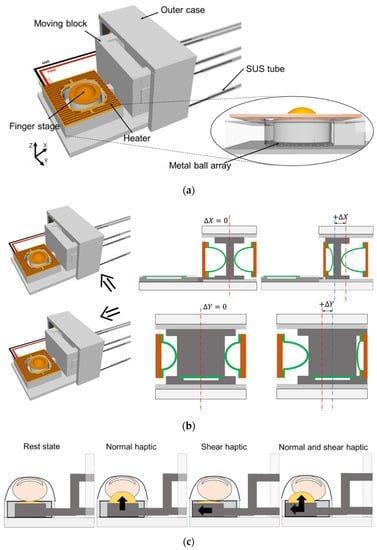
Figure 1.
Conceptual view of a three-axis pneumatic haptic display capable of expressing thermal sensation (excluding rubber strap for finger fixation). (a) Proposed device. (b) Side and rear view during operation. (c) Finger on the device and its operation for normal and shear haptics.
Figure 2 shows the dissembled figure and its dimensions. The size of the device is 48 × 35 × 18 mm3. The radius of the four balloons for lateral actuation is 4.5 mm, and the radius of the balloon on the finger stage for the normal haptic display is 4 mm. The gap between the moving block and the side wall with balloon rubber is 1.5 mm when the moving block is at the center position. Therefore, the moving block can move up to ±1.5 mm in both x- and y-directions.
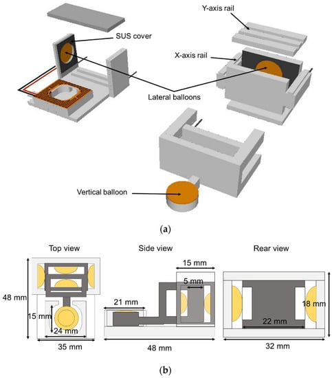
Figure 2.
Disassembled view of the proposed device (a) and its dimension (b).
This displacement in the lateral direction is enough for shear haptic display because it is known that the finger pads have a deformation limitation in the shear direction of approximately 2 mm [33]. The finger stage is designed to have exterior and interior sizes of 15 × 15 mm2 and 24 × 21 mm2, respectively, to properly position a fingertip. As shown in Figure 2, a balloon is formed at the moving block, which can freely move in the lateral direction. This generates shear haptic feedback and normal haptic feedback to the finger positioned on top. The rails are designed for accurate motion in the desired direction and for the minimization of the yaw motion of the moving block. The lateral position data of the moving block and vertical inflation data are used to control the pneumatic regulator to inflate the balloons. A lookup table was prepared through a preliminary experiment to move the block to a desired position, and the appropriate channel pressure was designated for each position. In addition, a SUS cover was attached to the rubber membrane balloon to withstand a higher air pressure. A metal ball array was installed on the body in contact with the finger stage to minimize the friction between the finger stage and the body. A control box was designed to adjust the gain manually and compensate for the force caused by the finger gripping.
The heater located on the finger stage directly transfers the thermal sensation to the finger. The heater is made of a SUS film with a thickness of 0.2 mm and a total length of 270 mm and has an initial resistance of 5.3 Ω at 27 °C. The heater located on the finger stage directly transfers the thermal sensation to the finger. The heater is made of a SUS film with a thickness of 0.2 mm and a total length of 270 mm and has an initial resistance of 5.3 Ω at 27 °C. The heater was controlled via pulse-width modulation (PWM) to change the surface temperature from room temperature to over 90 °C without contact with a fingertip. When a finger is positioned on the finger stage and in contact with the heater, the heater temperature is below 46 °C because of its additional thermal mass. This is a good operational range because the thermal receptors of human skin respond between 5 and 45 °C [34].
3. Experiments
The proposed device is manufactured using a three-dimensional (3D) printer. Figure 3a shows the device parts printed using the 3D printer. In this study, polylactic acid materials with little cracking or shrinkage were used. After a manual assembly of the parts printed using the 3D printer, a 0.5-mm-thick rubber film was attached to the device to form balloons. As pneumatic connectors, SUS tubes with an inner diameter of 0.1 mm were inserted in the body to transmit external air pressure. The copper-patterned polyimide film was attached around the finger stage to form the heater. Figure 3b shows a photograph of the fabricated device and the device holding a finger. As shown in this figure, a rubber belt with Velcro was used to fix the finger tightly onto the finger stage.
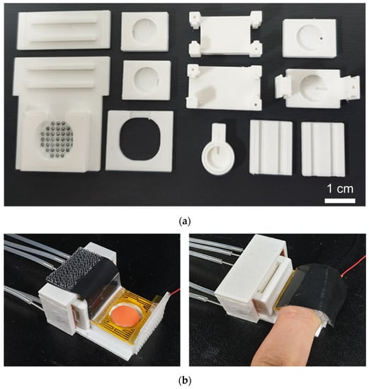
Figure 3.
Photos of the haptic display. (a) Parts printed by a 3D printer for the haptic display; (b) A fully assembled haptic display and the device holding a finger.
Figure 4 shows a custom-designed open-loop control module built to drive the proposed device. It is composed of a master microcontroller unit (MCU), slave MCU, liquid crystal display (LCD) monitor, and digital-to-analog converter (DAC). The master MCU controls five DACs to send a signal to the pneumatic regulator after receiving position data and calculating the required signal level for proper positioning. The slave MCU controls five DACs by receiving the calculated signal from the master MCU. The lateral axis connected to the master MCU, the lateral axis connected to the vertical axis slave MCU, and the gain (k) were adjusted through four knobs added to the module. An LCD monitor was added to check the gain (k) value.
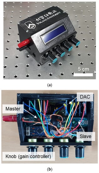
Figure 4.
Photo of a custom-designed control module (a) and its inside view (b).
Figure 5 shows the operation of the open-loop controller, where two haptic displays are managed by a single control module. The haptic data collected from the sensor and delivered to the module generate output signals for the inflation of the balloons and the thermal display through the heater. The sensory sensitivity differs from person to person during practical usage by an operator. Therefore, we designed the control module to control the gain (k) from 0 to 10, which varies the motion force and moving distance in lateral motion. The temperature was controlled using a PWM control method, in which the duty ratio of the current in the heater was controlled.
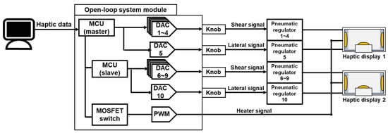
Figure 5.
Functional diagram of the custom-designed control module.
Figure 6 shows an experimental setup used to analyze the characteristics of the proposed device. The data on the lateral positions (x and y positions) and vertical inflation of the balloon are transferred to the control module through a computer to generate a proper voltage level to manage the output pressure of a pneumatic regulator. This pneumatic regulator provides pressurized air to each balloon of the devices. The control module calculates the output voltages required for the target lateral position and vertical pressure using the input haptic data and the gain value provided by the module’s knob. In addition to position control, the heater temperature for thermal haptic sensation is controlled by the PWM switching module embedded in the control module.
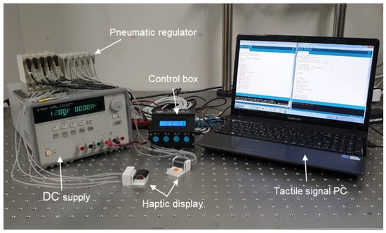
Figure 6.
Experimental setup for the three-axis haptic display.
The vertical force and displacement generated by the balloon on the finger stage were measured using a force gauge and microscope, respectively. The lateral displacement in the x- and y-directions was monitored using a camera and analyzed using graphic software.
4. Results and Discussions
Figure 7 shows the force and inflation height of a balloon in the normal direction when various input voltages were applied to the pneumatic regulator. The force by balloon inflation increased linearly with the input voltage, and a maximum force of 11 N was observed at the input voltage of 2 V. Accordingly, the inflation height was also linear, and the maximum height was approximately 3.8 mm.
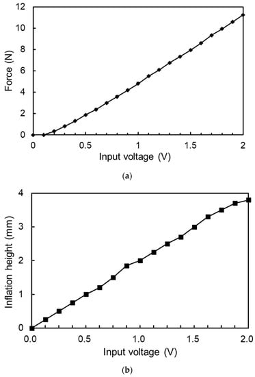
Figure 7.
Force (a) and inflation height (b) of a balloon in the normal direction at various input voltages.
Figure 8a shows photographs of the actuation in the two-dimensional (2D) lateral position control of the haptic display. To evaluate the lateral actuation, 14,400 coordinates were set by dividing an area of 3 × 3 mm2 into 120 × 120 grids in the x- and y- directions. Figure 8b shows the results of 2D position control without load or finger contact. The positional control was very accurate with an average error of less than 0.1 mm. For the open-loop control, the pressure ratios and the resultant voltage values for each balloon were prepared for each coordinate in the form of a lookup table.
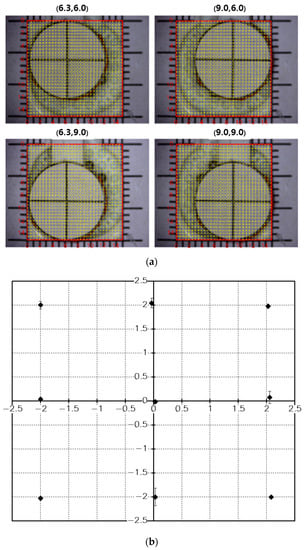
Figure 8.
(a) Photo of the experimental procedure measuring the displacement in the lateral direction. (b) Displacement accuracy in lateral position control without finger contact.
Although the lateral actuation was accurate, large hysteresis and positional errors were observed when a finger was fixed onto the finger stage. To address this problem, the gain control function was embedded in the control module, where the gain (k) could be controlled from 0 to 10 to enhance or reduce the pneumatic pressure ratio. Figure 9 shows the hysteresis according to the change in the gain value when the balloon membrane is driven in the lateral direction while pressing the finger stage with a force of 2 N. In these graphs, the vertical axis represents the displacement in the lateral direction, and the horizontal axis represents the command numbers in the lookup table required to arrive at the lateral positions. These experiments show that the larger the gain value, the smaller was the hysteresis obtained because the moving stage was operated by a larger pressure ratio between the two balloons on opposite sides. It can also be observed that the accuracy of arriving at the target position was improved with a high gain value.
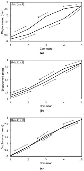
Figure 9.
Hysteresis showing positional accuracy in lateral motion according to the gain (k) value while pressing the finger stage with a force of 2 N. (a) k = 7; (b) k = 9; (c) k = 10.
The moving velocity of the finger stage is affected by the gain value. Figure 10 shows the time required to reach a target point 3 mm away for various gain values and vertical forces. When there was no vertical force, the maximum speed could be obtained when the gain was 8. However, when the vertical force was greater than 1.5 N, the maximum speed could be obtained for the gain value of 10. Therefore, the gain value must be adjusted according to the finger force required to press the finger stage.
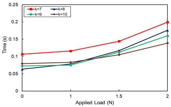
Figure 10.
Time required to reach a target point at a distance of 3 mm for various gain values and vertical forces.
The surface temperature of the heater was measured by using a resistance temperature detector. Figure 11 shows the temperature of the heater for various duty ratios of the PWM control signal. In this experiment, the temperature could be controlled by adjusting the duty ratio from room temperature up to 90 °C without a finger on the device. When a finger is positioned on the finger stage and in contact with the heater, the temperature of the heater changes because of the additional thermal mass. The temperature of the heater changes from 35 to 46 °C in accordance with the duty ratio when a finger is loaded on. We also performed a thermal simulation to expect the temperature of the heater by using commercial finite element software (COMSOL Multiphysics), as shown in Figure 12. During the simulation, a water-filled polymer shell structure was used to realize the effect of a finger, and the results are depicted with dot lines in Figure 11. As shown in the figure, the tendency of temperature according to input signals can be found to be relatively consistent in simulations and experiments. However, in the absence of a finger, the slope of temperature response for input power differed in simulations and experiments, presumably due to inaccurate model parameters for the material used.
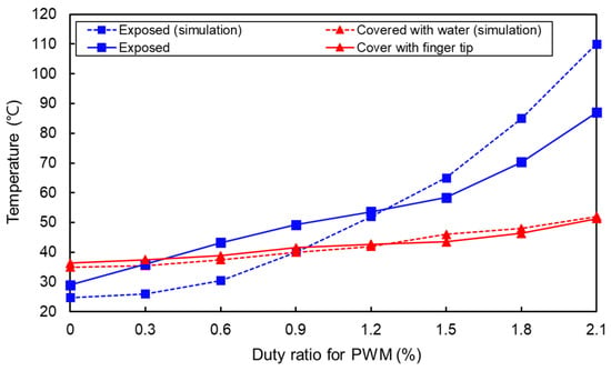
Figure 11.
Heater temperature according to the duty ratio of the PWM control signal.
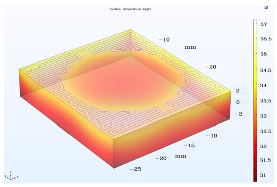
Figure 12.
Thermal analysis using finite element software (COMSOL).
Finally, in this work, we performed simple psychophysical experiments to test the ability of the proposed device to display both force and thermal stimuli on human fingers and see the effect of thermal sensation on the force feedback. From previous studies, it has been known that the degree of recognition of tactile stimuli varies depending on the temperature of the skin [35,36]. However, little research has been identified on the correlation between the surface temperature of an object and the recognition of shear stimuli on its fingers. Therefore, in this experiment, we would like to check the accuracy of recognizing the shear displacement while changing the temperature of the surface where the fingers come into contact.
Six people aged 27–33 participated in this experiment. The experimental settings are shown in Figure 13a. The subject sat in front of the desk and placed his hand on the desk with one palm facing down. The index finger was positioned on the finger stage and fixed to the tactile display using the holding strap. In this experiment, we conducted experiments on three variables: temperature, gain (k), and displacement. The heater temperature was tested at room temperature (heater off), 41–42 °C, and 45–46 °C, respectively, and three displacements (1, 2, and 3 mm) were randomly applied to the finger of a subject at three different k values. At this time, the subjects assessed the accuracy by answering the extent of the currently authorized displacement according to the feeling of shear displacement acquired in advance.
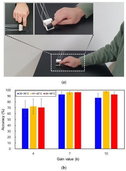
Figure 13.
Setup for psychophysical experiments (a) and accuracy measured at various heater temperatures (b).
As a result, a total of 81 experimental data were obtained for one subject. As shown in Figure 13b, there was no significant difference between k = 7 and 10, but the maximum accuracy was obtained when the gain was k = 7. Furthermore, in this experiment, we were able to confirm that the sensitivity to gain varies from person to person, but this requires further study through further experiments on the number of samples. Considering the error, there was no big difference in accuracy with temperature at the same gain value. This does not seem to have a significant relationship between the force and the thermal haptics, at least in the range of temperatures conducted in this study. This result is different from previous studies in that spatial acuity and the vibrotactile perception threshold vary depending on temperature [35,37]. However, since the number of experimental samples was not large and the range of temperature was not wide, the exact correlation needs to be studied later.
5. Conclusions
In this study, a pneumatic three-axis haptic display capable of expressing thermal sensation was proposed, implemented, and experimentally demonstrated by evaluating the haptic feedback of force and temperature. In the force feedback, both normal and shear haptic displays were demonstrated using an independently controlled three-axis actuator. In addition to the force feedback, the thermal sensation to the operator’s finger was demonstrated using a heater made of a thin SUS film integrated into the device. The output force and displacement for the haptic feedback were linearly proportional to the input voltage applied to the pneumatic regulator. The temperature of the heater was controlled from room temperature up to 90 °C through a PWM signal. The modifying gain method was applied to the custom-designed control module to minimize the hysteresis and load effects of the finger during position control. The maximum position error was 0.45 mm when the gain was controlled, and the error was reduced to within 0.1 mm. Psychophysical experiments have shown that cognitive accuracy is affected by gain and temperature is not significantly affected, but further research is needed to confirm the exact association.
Author Contributions
E.-H.L. fabricated the device, conducted experiments, evaluated the data, and wrote this paper. S.-H.K. presented the idea, designed the experiment. K.-S.Y. contributed to the data analysis, the verification of the approach, and reviewed the paper. All authors have read and agreed to the published version of the manuscript.
Funding
This work was supported by the Technology Innovation Program (10077620) funded by the Ministry of Trade, Industry and Energy (MOTIE, Korea) and the MSIT (Ministry of Science and ICT), Korea, under the ITRC (Information Technology Research Center) support program (IITP-2021-2018-0-01421) supervised by the IITP (Institute of Information and Communications Technology Planning and Evaluation).
Institutional Review Board Statement
Not applicable.
Informed Consent Statement
Not applicable.
Data Availability Statement
Data is contained within the article.
Conflicts of Interest
The authors declare no conflict of interest.
References
- King, C.; Franco, M.; Culjat, M.O.; Higa, A.T.; Bisley, J.W.; Dutson, E.; Grundfest, W.S. Fabrication and Characterization of a Balloon Actuator Array for Haptic Feedback in Robotic Surgery. ASME J. Med. Devices 2008, 2, 041006. [Google Scholar] [CrossRef]
- Laycock, S.D.; Day, A.M. Recent Developments and Applications of Haptic Devices. Comput. Graph. Forum 2003, 22, 117–132. [Google Scholar] [CrossRef]
- Culjat, M.; King, C.; Franco, M.; Bisley, J.; Grundfest, W.; Dutson, E. Pneumatic balloon actuators for tactile feedback in robotic surgery. Ind. Robot 2008, 35, 449–455. [Google Scholar] [CrossRef]
- Yun, S.; Yoo, J.; Lim, S.; Park, J.; Lee, H.-K.; Yun, K.-S. Three-axis pneumatic tactile display with integrated capacitive sensors for feedback control. Microsyst. Technol. 2016, 22, 275–282. [Google Scholar] [CrossRef]
- Gallo, S.; Son, C.; Lee, H.J.; Bleuler, H.; Cho, I.-J. A flexible multimodal tactile display for delivering shape and material information. Sens. Actuators A Phys. 2015, 236, 180–189. [Google Scholar] [CrossRef]
- Kontarinis, D.; Son, J.; Peine, W.; Howe, R. A tactile shape sensing and display system for teleoperated manipulation. In Proceedings of the 1995 IEEE International Conference on Robotics and Automation, Nagoya, Japan, 21–27 May 1995; pp. 641–646. [Google Scholar] [CrossRef]
- Minamizawa, K.; Prattichizzo, D.; Tachi, S. Simplified design of haptic display by extending one-point kinesthetic feedback to multipoint tactile feedback. In Proceedings of the 2010 IEEE Haptics Symposium, Waltham, MA, USA, 25–26 March 2010; pp. 257–260. [Google Scholar] [CrossRef]
- Yoo, J.; Yun, S.; Lim, S.-C.; Park, J.; Yun, K.-S.; Lee, H.-K. Position controlled pneumatic tactile display for tangential stimulation of a finger pad. Sensors Actuators A Phys. 2015, 229, 15–22. [Google Scholar] [CrossRef]
- Shiokawa, Y.; Tazo, A.; Konyo, M.; Maeno, T. Hybrid display of realistic tactile sense using ultrasonic vibrator and force display. In Proceedings of the 2008 IEEE/RSJ International Conference on Intelligent Robots and Systems, Nice, France, 22–26 September 2008; pp. 3008–3013. [Google Scholar]
- Kuroki, S.; Kajimoto, H.; Nii, H.; Kawakami, N.; Tachi, S. Proposal for tactile sense presentation that combines electrical and mechanical stimulus. In Proceedings of the Second Joint EuroHaptics Conference and Symposium on Haptic Interfaces for Virtual Environment and Teleoperator Systems (WHC’07), Tsukuba, Japan, 22–24 March 2007; pp. 121–126. [Google Scholar]
- Doh, E.; Yoo, J.; Lee, H.; Park, J.; Yun, K.-S. Microfabrication of Three-Axis Tactile Feedback Actuator for Robot-Assisted Surgery. Jpn. J. Appl. Phys. 2013, 52, 17302. [Google Scholar] [CrossRef]
- Fukuda, T.; Morita, H.; Arai, F.; Ishihara, H.; Matsuura, H. Micro resonator using electromagnetic actuator for tactile display. In Proceedings of the 1997 International Symposium on Micromechanics and Human Science, Nagoya, Japan, 5–8 October 1997; pp. 143–148. [Google Scholar] [CrossRef]
- Kajimoto, H.; Kawakami, N.; Maeda, T.; Tachi, S. Electrocutaneous display as an interface to a virtual tactile world. In Proceedings of the IEEE Virtual Reality 2001, Yokohama, Japan, 13–17 March 2001; pp. 289–290. [Google Scholar] [CrossRef]
- Tang, H.; Beebe, D. A microfabricated electrostatic haptic display for persons with visual impairments. IEEE Trans. Rehabil. Eng. 1998, 6, 241–248. [Google Scholar] [CrossRef]
- Wagner, C.; Lederman, S.; Howe, R. A tactile shape display using RC servomotors. In Proceedings of the 10th Symposium on Haptic Interfaces for Virtual Environment and Teleoperator Systems, Orlando, FL, USA, 24–25 March 2002; pp. 354–355. [Google Scholar]
- Ikei, Y.; Wakamatsu, K.; Fukuda, S. Texture presentation by vibratory tactile display-image based presentation of a tactile texture. In Proceedings of the IEEE 1997 Annual International Symposium on Virtual Reality, Albuquerque, NM, USA, 1–5 March 1997; pp. 199–205. [Google Scholar]
- Taylor, P.M.; Hosseini-Sianaki, A.; Varley, C.J. Anelectrorheological fluid-based tactile array for virtual environments. In Proceedings of the IEEE International Conference on Robotics and Automation, Minneapolis, MN, USA, 22–28 April 1996; pp. 18–23. [Google Scholar]
- Sato, K.; Igarashi, E.; Kimura, M. Development of non-constrained master arm with tactile feedback device. In Proceedings of the Fifth International Conference on Advanced Robotics ’Robots in Unstructured Environments, Pisa, Italy, 19–22 June 1991; Volume 1, pp. 334–338. [Google Scholar]
- Konishi, S.; Kawai, F.; Cusin, P. Thin flexible end-effector using pneumatic balloon actuator. Sensors Actuators A Phys. 2001, 89, 28–35. [Google Scholar] [CrossRef]
- Monkman, G.J.; Taylor, P.M. Thermal tactile sensing. IEEE Trans. Robot. Autom. 1993, 9, 313–318. [Google Scholar] [CrossRef]
- Kim, J.J.; Wang, Y.; Wang, H.; Lee, S.; Yokota, T.; Someya, T. Skin Electronics: Next-Generation Device Platform for Virtual and Augmented Reality. Adv. Funct. Mater. 2021, 2009602. [Google Scholar] [CrossRef]
- Lim, S.-C.; Lee, H.-K.; Doh, E.; Yun, K.-S.; Park, J. Tactile display with tangential and normal skin displacement for robot-assisted surgery. Adv. Robot. 2014, 28, 859–868. [Google Scholar] [CrossRef]
- Gallo, S.; Rognini, G.; Santos-Carreras, L.; Vouga, T.; Blanke, O.; Bleuler, H. Encoded and cross modal thermal stimulation through a fingertip-sized haptic display. Front. Robot. AI 2015, 2, 25. [Google Scholar] [CrossRef]
- Yang, G.-H.; Kwon, D.-S. Effect of temperature in perceiving tactile stimulus using a thermo-tactile display. In Proceedings of the 2008 International Conference on Control, Automation and Systems, Seoul, Korea, 14–17 October 2008; pp. 266–271. [Google Scholar]
- Yang, G.-H.; Kyung, K.-U.; Srinivasan, M.; Kwon, D.-S. Quantitative tactile display device with pin-array type tactile feedback and thermal feedback. In Proceedings of the 2006 IEEE International Conference on Robotics and Automation, Orlando, FL, USA, 15–19 May 2006; pp. 3917–3922. [Google Scholar]
- Guiatni, M.; Kheddar, A. Theoretical and experimental study of a heat transfer model for thermal feedback in virtual environments. In Proceedings of the 2008 IEEE/RSJ International Conference on Intelligent Robots and Systems, Nice, France, 22–26 September 2008; pp. 2996–3001. [Google Scholar]
- Citerin, J.; Pocheville, A.; Kheddar, A. A touch rendering device in a virtual environment with kinesthetic and thermal feedback. In Proceedings of the 2006 IEEE International Conference on Robotics and Automation, Orlando, FL, USA, 15–19 May 2006; pp. 3923–3928. [Google Scholar]
- Ho, H.-N.; Jones, L.A. Development and evaluation of a thermal display for material identification and discrimination. ACM Trans. Appl. Percept. 2007, 4, 13. [Google Scholar] [CrossRef]
- Ino, S.; Shimizu, S.; Odagawa, T.; Sato, M.; Takahashi, M.; Izumi, T.; Ifukube, T. A tactile display for presenting quality of materials by changing the temperature of skin surface. In Proceedings of the 1993 2nd IEEE International Workshop on Robot and Human Communication, Tokyo, Japan, 3–5 November 1993; pp. 220–224. [Google Scholar]
- Hou, C.; Wang, H.; Zhang, Q.; Li, Y.; Zhu, M. Highly Conductive, Flexible, and Compressible All-Graphene Passive Electronic Skin for Sensing Human Touch. Adv. Mater. 2014, 26, 5018–5024. [Google Scholar] [CrossRef]
- Nakatani, M.; Sato, K.; Sato, K.; Kawana, Y.; Takai, D.; Minamizawa, K.; Tachi, S. A Novel Multimodal Tactile Module that Can Provide Vibro-Thermal Feedback. In Proceedings of the AsiaHaptic2016, Kashiwanoha, Japan, 29 November–1 December 2016; pp. 437–443. [Google Scholar]
- Oh, J.; Kim, S.; Lee, S.; Jeong, S.; Ko, S.H.; Bae, J. A Liquid Metal Based Multimodal Sensor and Haptic Feedback Device for Thermal and Tactile Sensation Generation in Virtual Reality. Adv. Funct. Mater. 2020, 2007772. [Google Scholar] [CrossRef]
- Friedman, R.M.; Hester, K.D.; Green, B.G.; LaMotte, R.H. Magnitude estimation of softness. Exp. Brain Res. 2008, 191, 133–142. [Google Scholar] [CrossRef]
- Jones, L.A.; Ho, H.-N. Warm or Cool, Large or Small? The Challenge of Thermal Displays. IEEE Trans. Haptics 2008, 1, 53–70. [Google Scholar] [CrossRef] [PubMed]
- Stevens, J.C. Temperature can sharpen tactile acuity. Percept. Psychophys. 1982, 31, 577–580. [Google Scholar] [CrossRef]
- Gescheider, G.; Thorpe, J.M.; Goodarz, J.; Bolanowski, S.J. The effects of skin temperature on the detection and discrimination of tactile stimulation. Somatosens. Mot. Res. 1997, 14, 181–188. [Google Scholar] [CrossRef]
- Harazin, B.; Harazin-Lechowska, A.; Kałamarz, J. Effect of individual finger skin temperature on vibrotactile perception threshold. Int. J. Occup. Med. Environ. Health 2013, 26, 930–939. [Google Scholar] [CrossRef] [PubMed]
Publisher’s Note: MDPI stays neutral with regard to jurisdictional claims in published maps and institutional affiliations. |
© 2021 by the authors. Licensee MDPI, Basel, Switzerland. This article is an open access article distributed under the terms and conditions of the Creative Commons Attribution (CC BY) license (http://creativecommons.org/licenses/by/4.0/).