1. Introduction
In automobile, aerospace, medical equipment, and other industries, most metal workpieces are formed through welding, casting and other necessary processing procedures. They need to be polished to meet accepted standards. Most traditional polishing procedures are carried out manually. However, the polishing process produces a large amount of dust, corrosive chip fluid and noise, which can easily lead to safety accidents resulting in operators’ injury [
1,
2,
3]. Simultaneously, manual polishing faces disadvantages of low production efficiency, poor product accuracy and low consistency. It is necessary to get rid of manual polishing to achieve automation. The precision and consistency of the workpiece largely depends on whether the polishing tool and the contact surface maintain a constant force. Therefore, it is essential to adopt real–time force–control technology to control the contact force in the polishing process [
4].
At present, there are two commonly used force control methods for robots. The first method is joint force control [
5,
6,
7,
8]. It realizes force control in Cartesian space by controlling the force or torque of the robot joints. This method is usually applied to human–robot interaction (HRI), collision detection, and so on. Thus, the object of application is often a lightweight cooperative robot. The difficulty is that it is necessary to build accurate dynamic models for specific robots. There are many advanced machine–learning and deep–learning methods to solve complex models and high-uncertainty problems of manipulators [
9]. However, it is commonly known that industrial robots are not suitable for force–control tasks, and they have large inertia, flexibility in joints and considerable friction in the transmission system, which lead to poor force–control performance. The second method uses an external device (an end-effector) to perform force control [
10,
11,
12,
13]. An industrial robot called a macro manipulator and the end-effector called a mini manipulator constitute a macro-mini manipulator system. This method is often used in medical surgery [
14], assembly [
15], polishing [
2] and other tasks requiring precise force control. Although the whole structure becomes complex, each system retains advantages in operation. The mini manipulator has high bandwidth and low impedance [
3], while the macro manipulator has a large workspace. This concept was proposed by Sharon and Hardt [
16]. During operation, the macro moves according to traditional position control, and the mini achieves force control. Therefore, force control processing can be performed without the need for accurate industrial robot system dynamic modeling.
A nonrigid macro manipulator will start to vibrate even at low frequencies, which may limit the series-coupled mini manipulator force control performance. Many related studies have been carried out using intelligent materials and intelligent structures to suppress end-effector vibration. Fan [
17] proposed a novel intelligent end-effector for active-contact force control. Two novel eddy-current dampers were designed and integrated into the end-effector to improve the system dynamics and suppress vibration. Lou and Wei [
18] proposed a flexible manipulator with tip payload featuring surface-bonded piezoelectric torsional and shear actuators with a nonlinear controller for active vibration suppression. Chen [
19] proposed a novel 3-DoFs (Degree-of-Freedom) linear magnetic actuator, which increases the damping and static stiffness of flexible structures during machining. These methods could effectively reduce the vibration in a series macro-mini manipulator system, but the structure is complex and the cost is high.
Some researchers have used different control methods to adjust the dynamic of the macro manipulator. Sharon [
20] proposed an impedance matching method, which modified the impedance of the macro manipulator to dampen the resonance peak. Wang [
21] created a function of the contact force and vibration responses, and a force-control-based workpiece vibration control method was proposed. Labrecque [
22] proposed a unique control strategy to minimize the impedance of the manipulator. This could eliminate the nonlinear impedance to improve force performance simultaneously. Arifin [
23] introduced a general control framework for a macro-mini manipulator to improve the force and compliant motion control of robotic manipulators. Resolved Motion Rate Control (RMRC) was used as the controller for the macro manipulator while switching between position control and force control was applied for the mini. Cao [
24] proposed a novel particle swarm optimization (PSO) named CP-PSO to optimize joint trajectory and suppress robot vibration with specified constraints. Lin [
25] proposed an active damping control applied to the macro manipulator to suppress the vibration. Guo [
26] adopted a novel method that vibration suppression could be achieved by generating friction force to balance the cutting force based on the pressure foot. Other control algorithms can also achieve vibration suppression of contact force [
27,
28,
29]. Since the stiffness of the joint of the manipulator has a significant influence on that of the robot, the suppression of joint vibration is another primary method [
30,
31,
32]. However, many industrial robots do not provide an interface for users to arbitrarily modify robot dynamics because their control architecture is closed, so users cannot modify the control algorithms. Li [
33] proposed a zero-coupling impedance theory based on the macro-mini manipulator, which could theoretically improve the bandwidth of force control. However, it lacked a damped and rigid end-effector to further illustrate the feasibility. Others adopted advanced control algorithms such as deep-learning, machine-learning [
9] and mathematical prediction [
34,
35]. Pelayo [
36] selected the appropriate technological parameters of robotic processing by predicting the surface roughness of the workpiece to achieve the optimal processing effect.
Generally, the polishing tool moves from a noncontact state to a contact state. To avoid impact, the force is required to have compliance. The most common compliance control method is impedance control, which was proposed by Hogan [
37]. However, this requires accurate motion trajectory and appropriate impedance parameters for contact-force tracking [
38,
39,
40,
41]. This is suitable for robots that interact with changing environments. However, the contact-force response is slower due to the increase of the loop.
To enhance the system performance of a macro-mini manipulator, in this research, both the direct force control and impedance control are combined with impedance matching to realize the complete polishing process. The significant contribution is that impedance matching is introduced into the primary control strategy, and a suitable impedance is to match the dynamic coupling impedance to achieve vibration suppression for the macro-mini manipulator. The coupling impedance contains both mechanical impedance and control impedance between the macro and mini. The advantage of the proposed vibration suppression method is that it neither changes the dynamics of industrial robots nor complicates the architecture of control systems and mechanical systems.
The paper is organized as follows.
Section 2 introduces the structure of a force-controlled end-effector and the dynamic model of the macro-mini manipulator is established.
Section 3 introduces the direct force control, suggests impedance matching method, and presents simulations and experiments with the proposed control method.
Section 4 discusses the impedance control with impedance matching and then carries out the simulations and polishing experiments. Finally,
Section 5 summarizes the present study and future work is discussed.
3. Direct Force Control with Impedance Matching
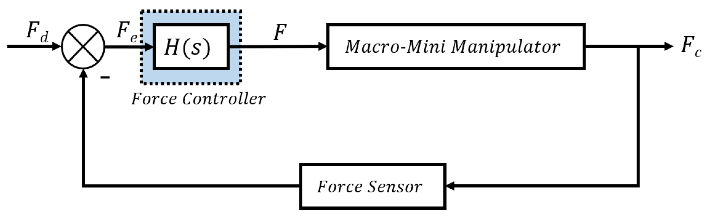
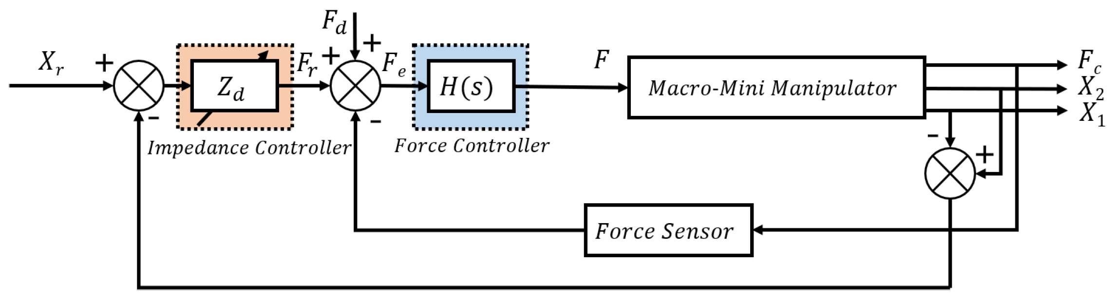
In the polishing operation, the end-effector needs to have the high force control precision to achieve the tracking of the desired force. The direct force control strategy uses the measured force for feedback to obtain the force error vector. Then the stable contact force can be obtained through the force controller. The control block diagram is shown in
Figure 3.
The relationship between the contact force and the desired force becomes:
where
is the force controller. Equation (
14) shows that the contact force is still affected by the macro manipulator’s vibration after the force controller is introduced. The antiresonance mode can be removed by choosing a proper
. However, the coupling impedance cannot be eliminated from springs, guide rail and other motion devices. Because these mechanical parts will produce force associated with motion when they move. Therefore, one solution was suggested that adding a matched impedance
to make the total impedance obtain a suitable value to eliminate
.
3.1. Impedance Matching
3.1.1. Analysis
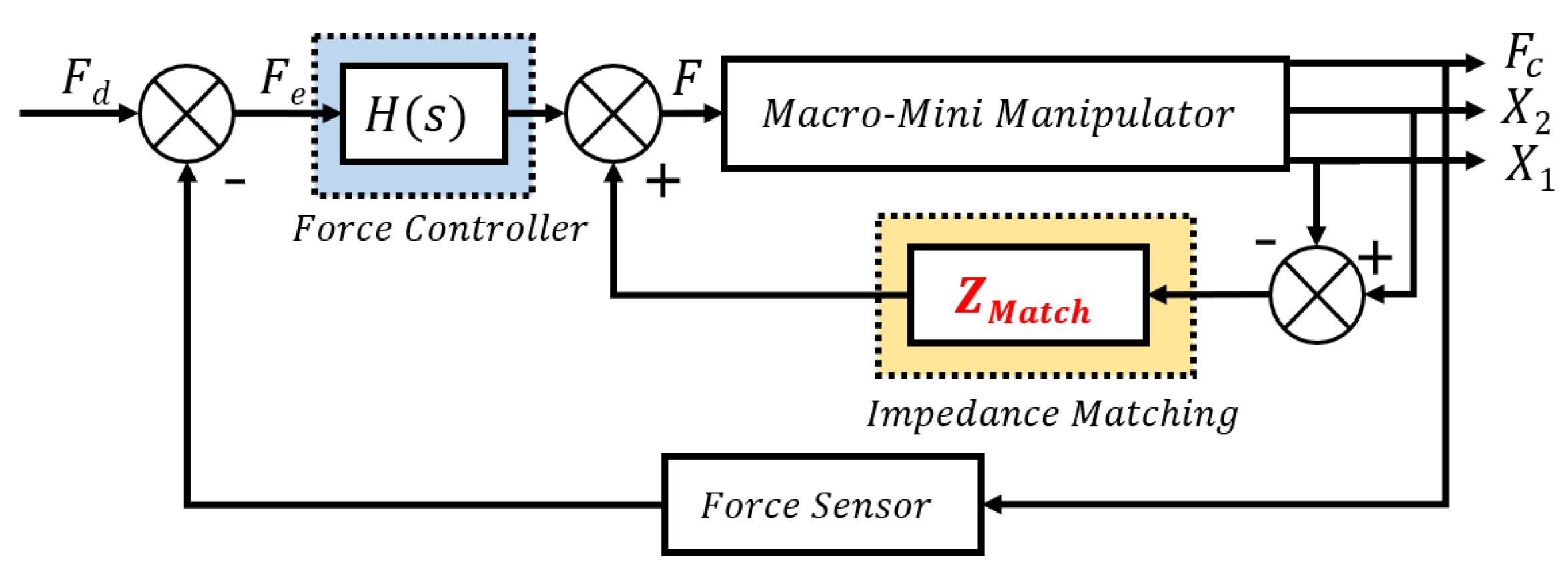
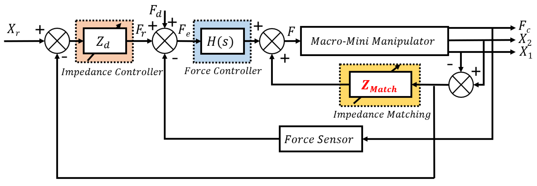
According to the previous analysis, the force generated by the relative motion between the macro and mini manipulator through the coupling impedance affects both the macro and mini. Based on the force control, an additional impedance
is introduced in the macro-mini manipulator system to match the coupling impedance. As shown in
Figure 4.
Here, the total impedance between the macro and mini is the sum of the coupling impedance
and the matched impedance
. The coupling impedance only includes mechanical impedance
. Hence Equation (
14) can be written as:
where:
In order to eliminate the influence of macro manipulator on force control performance, as shown in Equations (15) and (16), it can be found that the system impedance can match each other as long as it is designed
to make
ideally. So the transfer function becomes:
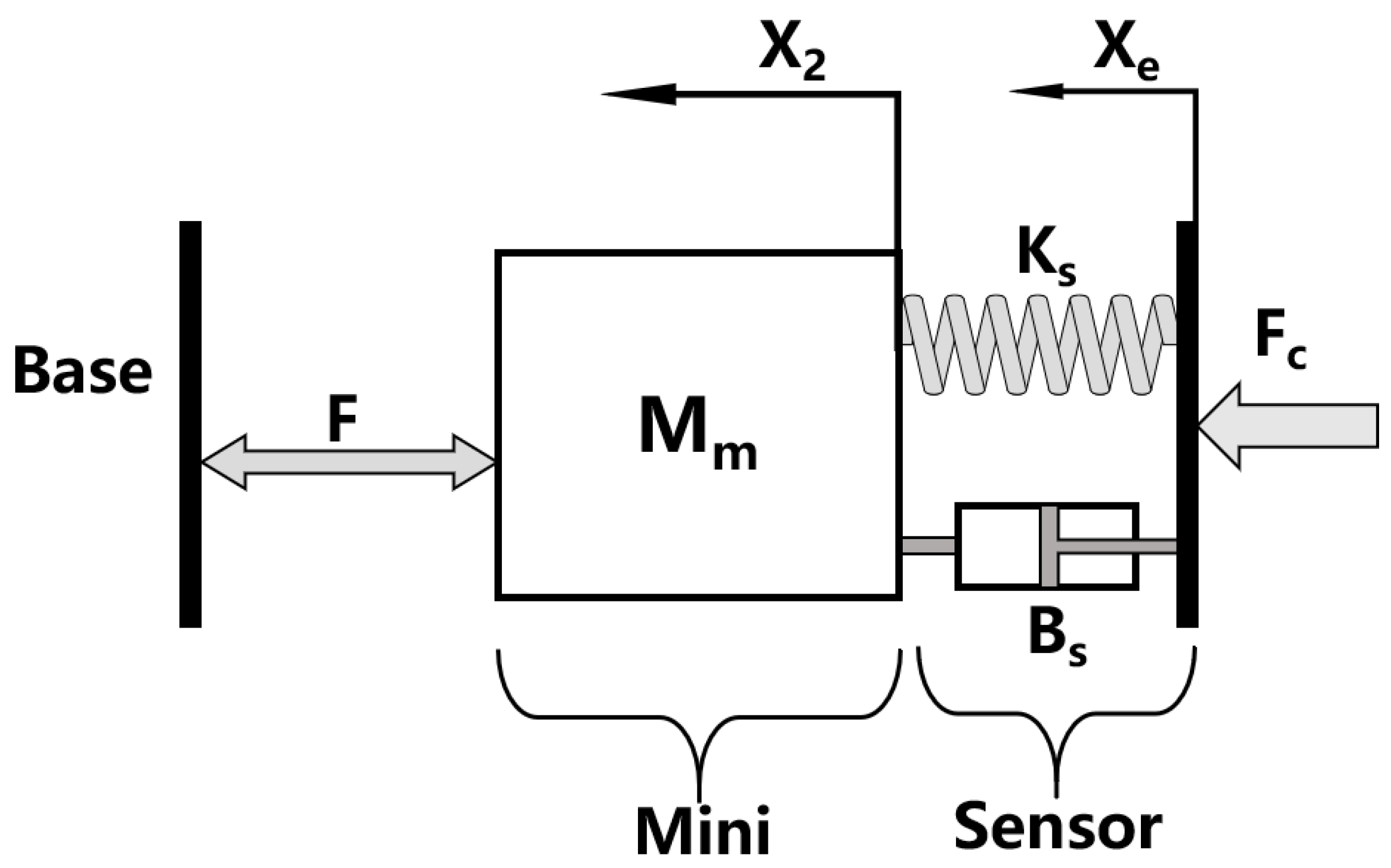
The macro manipulator will not affect the contact force between the tool and the surface of a workpiece. Hence, the macro-mini manipulator system is equivalent to installing the mini manipulator on the high stiffness base after introducing the impedance matching. As shown in
Figure 5.
3.1.2. Stability Condition
Through the previous analysis, the force controller selects the PID type, its algorithm is simple, robust and reliable, and is widely used in industrial process control. Its transfer function:
where
,
and
are the proportional, integral and differential gains respectively. Then the transfer function Equation (
18) is expanded:
The system’s characteristic equation is:
Based on Routh–Hurwitz criterion, and the known parameters, the condition of system stability is given:
3.2. Simulation
In this section, simulation analysis on the vibration problem is employed in the macro-mini manipulator. The mechanical impedance parameters of the mini manipulator are shown in
Table 1. Other simulation parameters of the macro and sensor do not represent real values. They are shown in
Table 2.
The force controller is PID type. Based on the stability condition and the integral of squared error (ISE) criterion [
43]. The proper gains are designed as:
,
,
. The constant force response and its force error are shown in
Figure 6. In
Figure 6a, the simulation of the end-effector alone is carried out first. The green line shows that only the mini manipulator is installed on a base with high stiffness which will not vibrate to affect the contact force. Its maximum overshoot of response is 6.3% (21.26 N) and the contact force is stable after 1.38 s. When the mini manipulator is installed at the end of the macro manipulator, its response of contact force is shown as the red line. The maximum overshoot is 11.5% (22.3 N). There is constant attenuation of vibration and it eventually converges to the desired force after 5.41 s. The impedance matching is introduced and the blue dotted line shows that the overshoot and decay time reduce to 6.7% (21.34 N) and 1.32 s, respectively.
Comparing the contact force obtained by controlling the end-effector, the force error curve can be obtained. The blue line in
Figure 6b shows the step force response of the macro-mini manipulator with impedance matching is constant with that of the end-effector. The red line shows the macro-mini manipulator will produce oscillation, but it will soon converge to 0 N.
3.3. Experiments
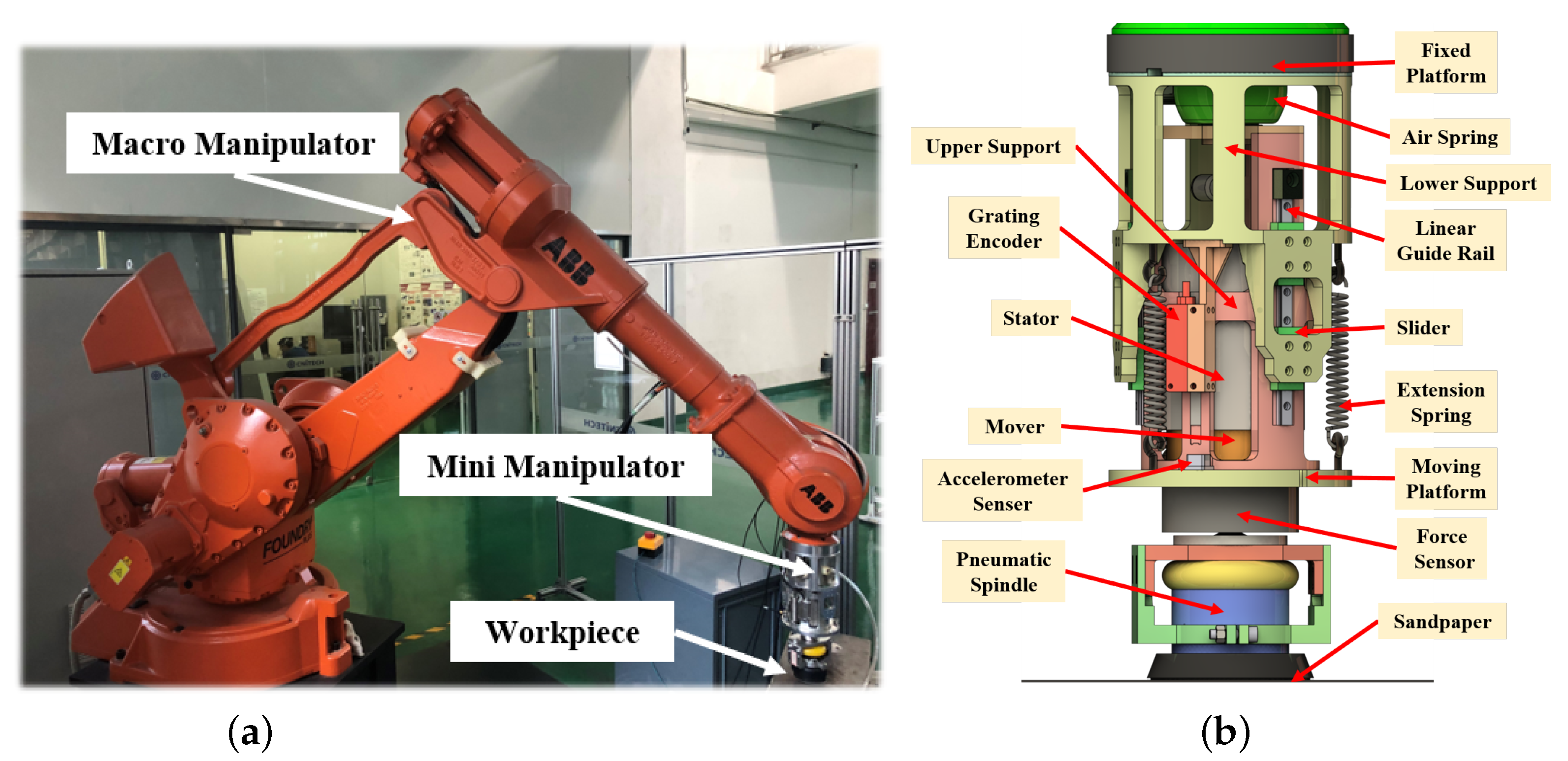
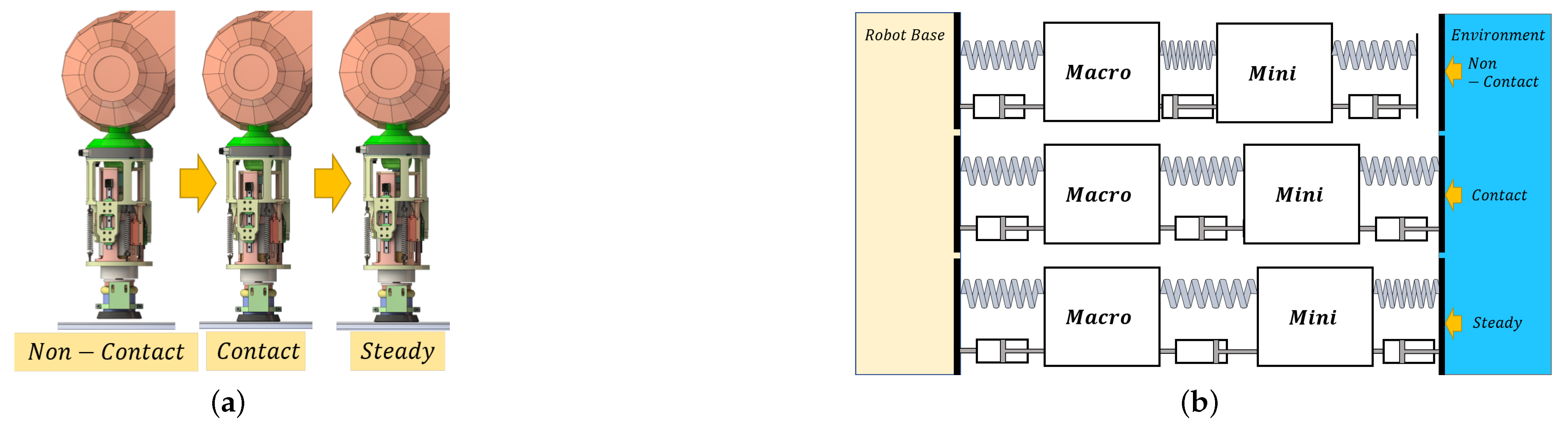
A contact force control experimental platform based on the force-controlled end-effector is built to verify the control effect of the impedance matching method on the system’s dynamic performance. The direct force control algorithm described in the previous subsection was implanted on the current prototype shown in
Figure 1a. In the experiments, the macro manipulator is ABB IRB 4400 which is a position control based industrial robot capable of carrying loads up to 60 kg. It is also capable of a broader range of applications with high accuracy, speed and flexibility.
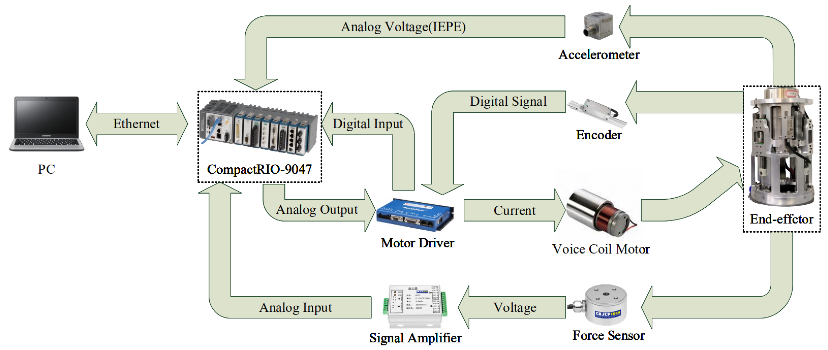
Figure 7 shows the experimental hardware composed mainly of PC, data acquisition system (NI-cRIO 9047), motor driver (Copley ACJ-055-18), force sensor, grating encoder and accelerometer sensor. The air path part mainly consists of air compressor, additional air chamber, pressure regulating valve, etc. Commonly used polishing tools are polishing brush, sandpaper [
13] and flexible abrasive tools [
44]. In this experiments, the abrasive tool is 180 mesh sandpaper which is suitable for flats with small curvature. The PC implement the control program’s writing and the processing of the collected data with LabVIEW. The data acquisition system collects feedback data to realize the force closed-loop control. It also sends external loop control instructions to motor driver. The sampling time of the system is 2 ms. According to the control command, the output force adjustment is realized by controlling the voice coil motor’s current. This current contains both the part obtained by the force controller and the other part obtained by the impedance matching controller. On the other hand, to consider the moving platform’s inertia force, the acceleration needs to be known. It is measured by the accelerometer sensor which is installed on the moving platform. The impedance matching controller contains an impedance opposite to the magnitude of the coupling impedance. Its inputs are the relative displacement variation of moving and fixed platforms measured by a grating encoder, and the velocity is obtained by displacement differential. Its output is compensation force.
When only considering the end-effector, and which is mounted on the base with high stiffness rather than the macro manipulator’s flange, its control block diagram is shown in
Figure 8. The force controller is PID type, based on the stability condition and the integral of squared error (ISE) criterion [
43]. Its gains are designed as
,
,
. The current loop with the
controller is employed inside the driver. The proportional and integral gain of the PI controller are designed as
,
by auto tune. Gravity is utilized as the offset compensation of the current. Contact force is the resultant force between the voice coil motor’s output force and the external interference force. Disturbing force refers to the elastic force and damping force produced by the extension springs and the air spring. During the experiment, the air spring is charged with an air pressure of 1 Bar and it is kept constant during the experiment, besides keeping the force controller parameters unchanged in the control loop in the experiments.
The force control response of the end-effector is shown in
Figure 9. Under the control of 20 N step force, the response time of the end-effector is about 20 ms. Its maximum overshoot is 22.6% (24.52 N) and its time for the force error to reach within 5% is 0.31 s. The force control accuracy is less than ±0.1 N.
In the following, when the end-effector is mounted at the end of industrial robot, the result of the constant force control experiment is shown in
Figure 10. Before impedance matching is introduced in the macro-mini manipulator, the red line indicates that the overshoot of response reaches 57.5% (31.49 N), and the settling time rises to 0.83 s. However, after the introduction of impedance matching according to the blue line, the overshoot of the step force response reaches 29.6% (25.95 N), and the settling time decreases to 0.5 s. Its performance index is close to that of direct force control of the end-effector alone in
Figure 9. Their response times are almost the same, about 20 ms, when the contact force reaches a steady state. The Fourier transform of the contact force is shown in
Figure 11. After introducing the impedance matching, the of the contact force’s amplitude decreases at steady state.
The direct force control is suitable for polishing operations in which the tool is always attached to the workpiece surface during the polishing stage. This stage realizes the fast and accurate desired force tracking. Even though the workpiece surface may be curved, the end-effector can quickly adjust the actual contact force to achieve constant force polishing operation.
In the actual polishing process, the tool is not always in contact with the workpiece, and there is a process from free space to constrained space as shown in
Figure 12. The macro manipulator carries the mini moves and enables the polishing tool to approach the workpiece surface quickly and stably. Then, through the mini manipulator, the polishing tool and the workpiece change from the noncontact state to the contact state with a certain contact force, so the control mode in this stage is compliant control. Because the workpieces are metal materials, when the tool contacts with the surface of a workpiece, it is easy to produce collision, even shock phenomenon. The workpiece surface and the tool are likely to cause damage, so in the process of contact, we need to achieve both contact force to change smoothly and to avoid impact shock to contact.
For the method of direct force control, the end-effector compliance is achieved through mechanical impedance, and it is difficult to adjust its mechanical stiffness or damping in processing. So this method is not applicable at noncontact stage. As shown in
Figure 13a, when the tool is 5 mm away from the workpiece, the overshoot of contact force is 97.7% (39.53 N). Moreover, its decay time is 0.88 s. Although the overshoot is reduced by 58.3% (27.88 N) after the addition of impedance matching, the oscillation time is still 0.45 s in
Figure 13b.
When the polishing spindle rotates, the result is shown in
Figure 14. The end-effector transforms from a free space to a constrained space, and its maximum overshoot reaches 104.4% (40.87 N). After impedance matching introduced into the controller, the overshoot reduces to 40.5% (28.09 N). The decay time reduces by 0.3 s. The contact force accuracy at the final steady-state is ±2 N. Obviously, when the polishing spindle rotates, the contact force error is more significant than when it does not rotate. It generates vibrations of frequencies associated with the speed. Therefore, it is inevitable that the accuracy of force control becomes worse due to the spindle rotation.
Due to the initial noncontact state, the direction of force applied by the mini is not constrained by the environment and the feedback force is zero, then the voice coil motor generates a large current after the force error through the force controller. So it will quickly impact the workpiece and produce a shock. For the large stiffness of the polishing tool, the workpiece and it will be collapsed and broken. Therefore, only the mechanical impedance is not enough. The control impedance is needed to be considered to improve the end-effector compliance.
4. Impedance Control with Impedance Matching
To make the end-effector compliant is not limited by mechanical impedance, controllable impedance is needed. So the impedance control is introduced. In general, impedance control is used to control the joint force or torque to make the manipulator show the desired impedance characteristics. In this paper, the controlled object is the 1-DoF end-effector, which can be regarded as a prismatic joint. Therefore, the impedance relationship can be directly established for the end-effector, which is equivalent to the spring-mass-damping model. Therefore, the impedance relationship between them is adjusted by changing the inertia, damping and stiffness coefficients.
The control system of impedance control is composed of internal force closed-loop control and external loop of impedance regulation, as shown in
Figure 15. According to the system reference motion state, the actual motion state and the desired impedance model, the impedance controller generates reference force function. Finally, through the force controller of the internal loop, the actual force between the mini and the environment can track the force consisting of
and
.
In the impedance controller, the reference force can be obtained:
where:
is the reference position for
. Its value is calculated by desired force, actual position and known system parameters.
is reference force calculated by Equation (
23).
is desired force. Due to there will be an error in the actual position, the reference value
is an approximation.
and
are the desired damping and stiffness coefficients which are variable. In the contact force tracking phase, they become to zero. So the reference force is zero to make contact force can track the desired force in final.
4.1. Impedance Matching
4.1.1. Analysis
On the basis of impedance control, the impedance matching method is introduced into the force loop. The control block diagram is shown in
Figure 16. The transfer function between the contact force and the reference position is:
where:
Here, the coupling impedance includes:
where
.
is the mechanical impedance as shown in
Table 1. In order to eliminate the influence of the macro manipulator on the terminal contact force, both the control impedance and the mechanical impedance need to be eliminated:
Impedance control can improve the compliance when the mini manipulator moves from noncontact stage to contact stage. However, there is a steady-state error between the approximate force and the desired force due to the approximate reference position. To realize the desired force tracking, setting as desired force and the output of the impedance control is zero. When the contact force is stable, the impedance controller’s parameters gradually become zero. Simultaneously, the matched impedance parameters gradually changes from the initial value to the mechanical impedance value only.
4.1.2. Stability Condition
The impedance control is force control based on position feedback. The stability of the force loop has been proved in
Section 3. As well as the external position loop is stable, the whole system can be stable. Based on the dynamics of the macro and mini manipulator, the relative position of the moving platform and fixed platform can be obtained:
According to Equations (13) and (26), the above equation can be written as:
So the characteristic equation of the closed loop transfer function
is:
Based on Routh–Hurwitz criterion, the conditions of system stability are given:
The system’s stability is unrelated to the parameters of impedance controller. In the proposed controller, the parameters of impedance controller can be any value. As long as the PID gains satisfy these conditions, the system will be stable. When they are zero, the control loop becomes the direct force control whose stability is proved in
Section 3.
4.2. Simulation
In this section, simulation analysis on the impedance control is carried out in the macro-mini manipulator. The force controller is PID type. Its gains are the same as that in direct force control simulation. Other parameters are shown in
Table 2.
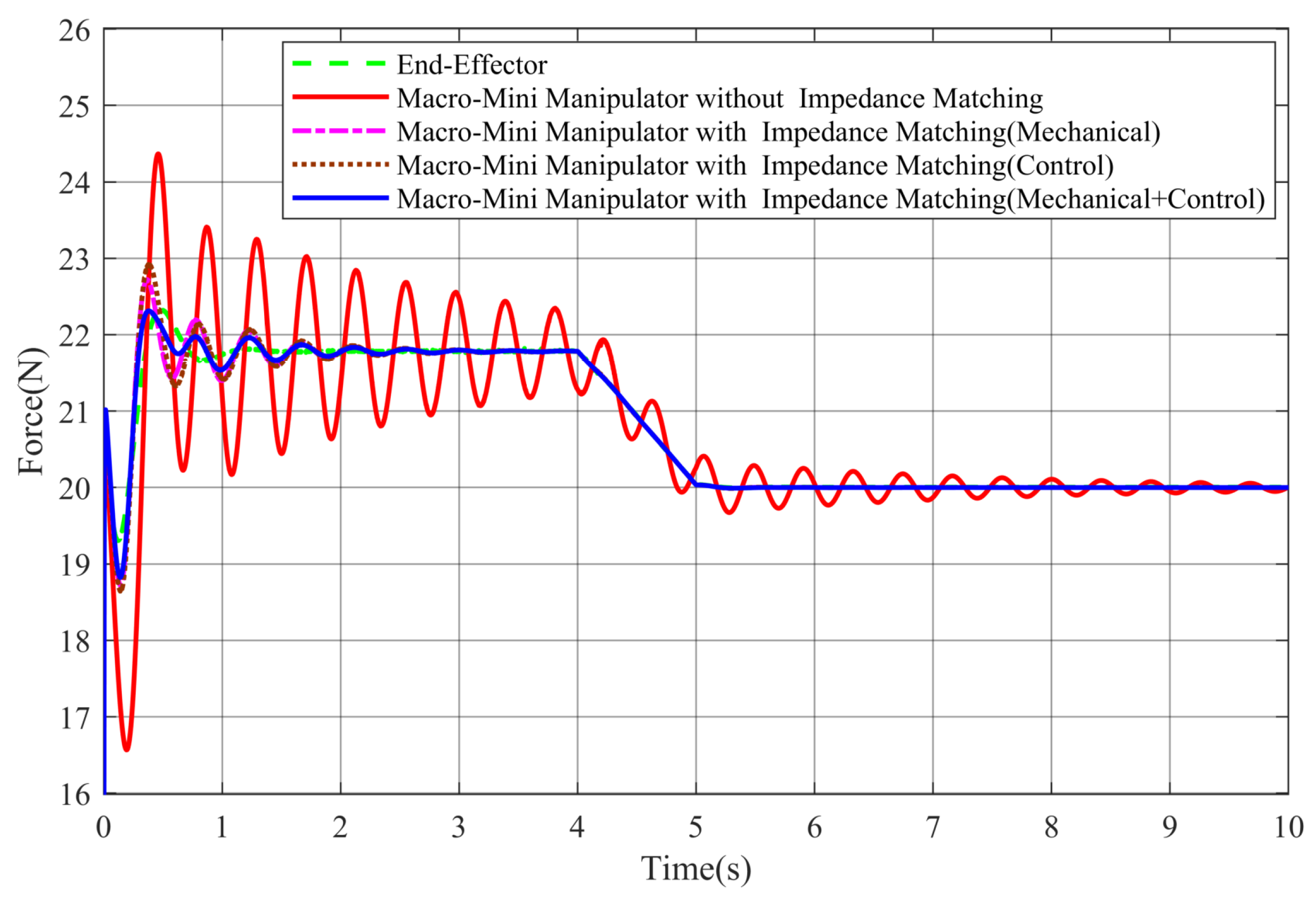
The result is shown in
Figure 17. When the position and force reach dynamic equilibrium, the sum of the reference force and desired force is 21.8 N. From 4 s to 5 s, the impedance controller’s parameters gradually become to zero. Then the impedance control simulation is performed on the end-effector alone, and the overshoot is 2.3% (22.3 N) and the decay time is 0.63 s, as shown by the green dot-dash line. For the macro-mini manipulator, the result is shown by the red solid line. The maximum overshoot of the contact force reaches 11.9% (24.4 N), and the decay time is 6.39 s. After introducing impedance matching, if the additional impedance only contains mechanical impedance, the pink dot-dash line expresses the contact force’s overshoot decreases to 4.1% (22.7 N), the decay time reduces to 1.28 s. If the additional impedance only contains control impedance, the brown dotted line shows its overshoot decreases to 5.1% (22.9 N). The decay time reduces to 1.48 s. When it contains both mechanical and control parts, its overshoot further reduces to 2.8% (22.4 N). The decay time is 0.64 s.
The simulation results suggest that the impedance matching is introduced in impedance control; the end-effector’s vibration can be suppressed no matter the additional impedance included in the mechanical part or the control part. When the two parts of impedance are included, the contact force response is optimal.
4.3. Experiment
By adjusting the macro manipulator’s position, the polishing tool is kept 5 mm away from workpiece’s surface. In the experiment, the parameters of impedance controller are
= 3 N/(mm/s) and
= 7 N/mm. The PID gains are the same as that in direct force control experiment. The desired force is set as 20 N. The value of the reference position is calculated by the desired force and impedance controller parameters. When the contact force is stable, the parameters of impedance controller are reduced to zero. So the output of the impedance controller is zero. Only the desired force becomes the input of the force loop. Simultaneously, the parameters of the impedance matching controller change from the sum of mechanical and control impedance to the mechanical impedance. So the control loop is the same as the direct force control. The polishing spindle does not rotate. When the force is stable, transforming the desired force between 5 N and 20 N. Its results are shown in
Figure 18 and
Figure 19.
This experiment represents the entire process of force control, from contact to stabilization, and then realizing force tracking. It verifies that impedance control can improve the compliance of end-effector compared with
Figure 13. In
Figure 18, the impedance matching is not introduced in the control loop. When the polishing tool comes into contact with the workpiece, its maximum overshoot is 20.3%. The parameters of the impedance controller begin decreasing at 3.675 s, become zero after 0.065 s and then change the desired force to 5 N. Its overshoot is 46.6%. When the desired force changes from 5 N to 20 N, its overshoot is 28.9%. After introducing the impedance matching in impedance control, the result is shown in
Figure 19. Its maximum overshoot reduces to 5.3% when the polishing tool comes into contact with the workpiece. The parameters of the impedance controller begin decreasing at 3.625 s. Furthermore, they become zero at 3.915 s. Then they change the desired force to 5 N. Its overshoot is 26.4%. When the desired force changes from 5 N to 20 N, its overshoot decreases to 12.2%. The results in
Table 3 show that impedance matching in the impedance control can effectively achieve vibration suppression. In fact, it is direct force control when the desired force changes. Whether impedance control or direct force control is adopted, the vibration of contact force decreases obviously with impedance matching in the whole polishing process.
When the polishing spindle rotates with a high speed, the target contact force is still 20 N. Impedance control with impedance matching is tested in the macro-mini manipulator. The experimental results are shown in the
Figure 20 and
Figure 21.
Compared with the direct force control in
Figure 14a,
Figure 20 shows the maximum overshoot of contact force reduces to 38.2% (26.97 N) according to the impedance controller’s output force and desired force (19.51 N). The parameters of impedance controller change to zero from 5.80 s to 5.90 s. When impedance matching is introduced in the macro-mini manipulator, the sum of the reference force and desired force is 19.88 N.
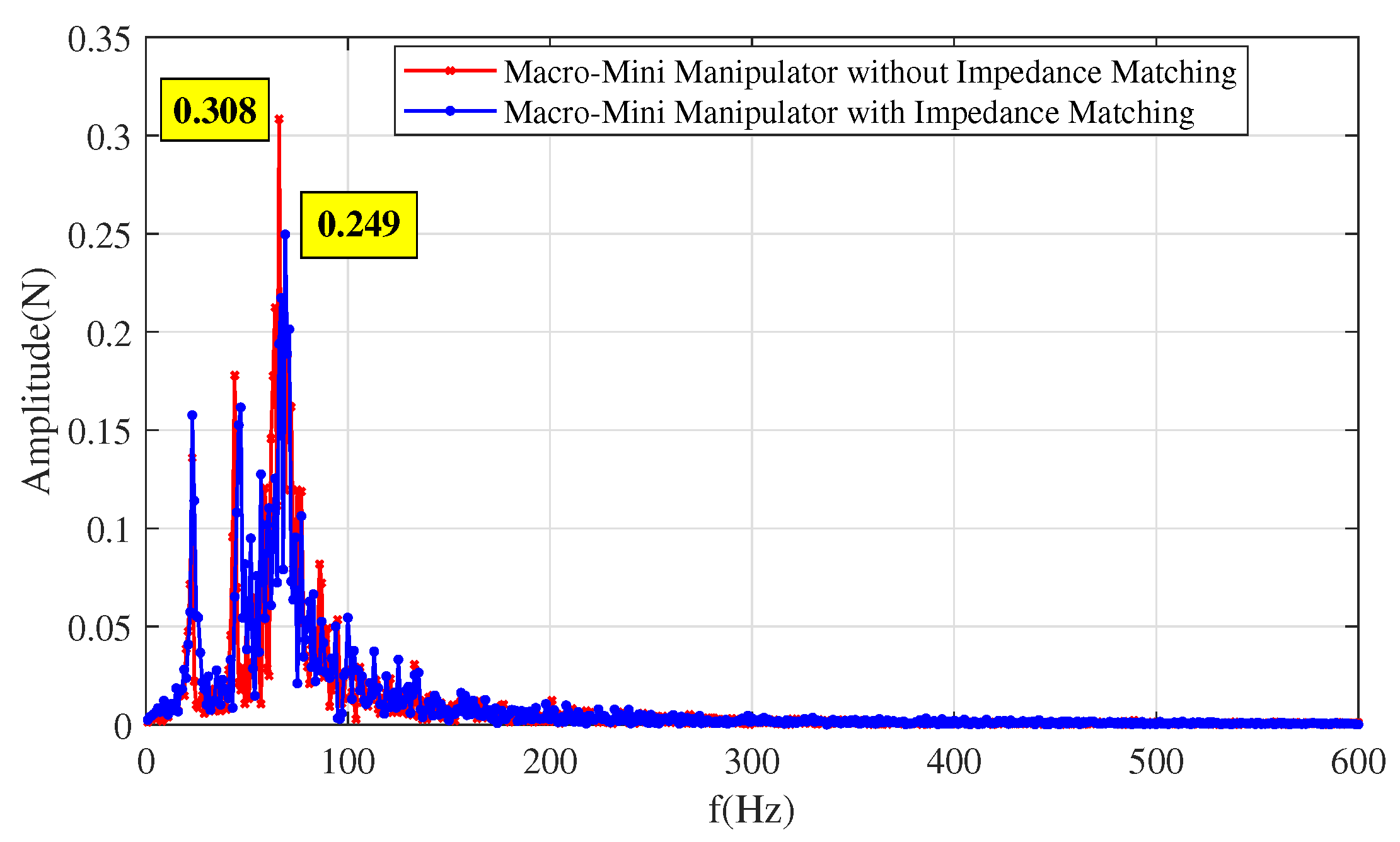
Figure 21 shows the force’s maximum overshoot further reduces to 10.3% (21.92 N). Due to the polishing tool being eccentric to the center of the spindle, the contact point will vibrate while rotating. The force precision is ±2 N. When the contact force reaches steady state, its Fourier transform is shown in
Figure 22. Compared with the amplitude in
Figure 11, it increases because of the spindle’s rotation. After introducing the impedance matching, the amplitude of the contact force’s amplitude decreases at steady state.
In summary, impedance matching can be carried out in both direct force control and impedance control. The vibration of contact force is suppressed effectively in the whole polishing process.


 ,
, 


