Article

Torque Characteristics Analysis of a Magnetorheological Brake with Double Brake Disc

Key Laboratory of Conveyance and Equipment, Ministry of Education, East China Jiaotong University, Nanchang 330013, China
*
Author to whom correspondence should be addressed.
Actuators 2021, 10(2), 23; https://doi.org/10.3390/act10020023
Submission received: 11 December 2020 / Revised: 29 December 2020 / Accepted: 23 January 2021 / Published: 27 January 2021
(This article belongs to the Section Actuators for Land Transport)

Abstract

:
Magnetorheological (MR) brake is a sort of electromagnetic brake that uses the controllable output characteristics of MR fluid for braking. In this paper, an MR brake with a double brake disc was developed to improve the braking performance of conventional MR brakes. The effective damping gaps were increased from the traditional two sections to four sections by increasing the single brake disc of the conventional MR brake to a double brake disc. By reasonably arranging the non-magnetic sleeve inside the MR brake, the magnetic flux lines were better guided to the effective damping gaps, which increased the utilization rate of the magnetic field, effectively enhanced the braking performance, and also reduced the braking power consumption. The structure and working principle of the MR brake with double brake disc were discussed. The magnetic field of the proposed MR brake was analyzed by ANSYS software, and the theoretical result of braking performance was obtained by combining the established mechanical model. The braking performance test rig was setup to investigate the torque performance of the MR brake. The experimental results show that the maximum braking torque is 18.01 N·m at the applied current of 2.0 A and the rotational speed of 400 r·min−1, and the simulation values are basically verified. In addition, the results indicate that the constant torque characteristic of the MR brake is relatively stable, and the torque is almost unaffected by the changes of rotational speed. The results can provide some guidance for the structural design and optimization of the MR actuators.

1. Introduction

Magnetorheological (MR) fluid, which consists of carbonyl iron powder and carrier liquid, is a sort of intelligent industrial material [1]. MR fluid exhibits its unique rheological properties, that is, when exposed to an external magnetic field, it can respond quickly within milliseconds and change from the fluid state to a solid-like state, thus generating the shear stress required for work [2,3,4,5]. The shear stress can be reversibly and consecutively adjusted by changing applied current to coordinate the internal magnetic flux density [6]. As a kind of semi-active control device, MR actuators work based on the rheological properties of MR fluids, which have attracted more and more attention due to their excellent controllability, rapid response, low power consumption, and simple structure [7,8]. According to the working mode, there are many MR actuators, such as, MR valves [9,10], MR dampers [11,12], MR brakes [13,14], and MR clutches [15]. These types of controllable devices are widely applied in vehicle systems, machining, rehabilitation equipment [16,17], and other industrial fields.
The MR brake is a representative MR actuator. It can effectively shorten the braking distance, reduce the braking lag time, and conveniently realize the integration of various new control technologies compared to traditional hydraulic brakes [18]. The disc-type MR brake is mainly composed of brake discs and the housing, and the rheological characteristics of the MR fluid are used to achieve braking performance.
At present, the MR brake still faces the problem of insufficient braking torque, which hinders its application range [19,20,21]. The typical methods for increasing the braking torque are to improve the rheological properties of MR fluid, modify the structure of the MR brake, and increase the strength of the internal magnetic field. In order to obtain MR fluid with high performance, Wang et al. [22] compared the performance of a variety of MR fluids with different particle volume fractions. The test results show that within a certain range, with an increase in the particle volume fraction of magnetic powder, there is an increase in rheological characteristics of the MR fluid. Patel et al. [23] synthesized and developed a non-spherical iron particle MR fluid for MR brakes, and the comparison results prove that the non-spherical particle MR fluid has a 17% higher braking torque and a smaller hysteresis loss than the conventional spherical MR fluid. In addition, the most common method to enhance the braking performance is to improve the structure of the MR brake. Nam et al. [24] proposed an MR brake incorporating a brake disc with a wave-shaped boundary, which provides braking torque produced by the effects of material deformation process. The results illustrate that the output torque with this kind of structure is close to 600% larger than that of conventional brakes. Qin et al. [25] proposed a miniature multi-drum MR brake, which has three effective brake drums inside so that there are more braking areas under a limited volume. The utilization of the magnetic field is maximized, the torque–volume ratio of the brake is 27.86 kN·m−2, and the braking time is relatively short. Liu et al. [26] designed a single-disc MR brake for the haptic device. The optimal sizes of the brake were obtained through finite element software, which greatly improved the performance of the brake. The maximum braking torque reaches 7 N·m, and the torque–volume ratio reaches 17.45 kN·m−2 at the applied current of 2 A. Wang et al. [27] designed a multi-cylindrical MR brake. There is a total of sixteen brake cylinders inside to provide eighteen sections of effective damping gaps. In order to reduce the overall volume of the brake, the excitation coil is placed sideways along with the axial position, and the structure is more compact. The results show that this structure can provide larger braking torque, but the multi-cylindrical structure is too complex, and the structure is easily damaged due to the brake cylinder under the action of force and thermal load, so the stiffness problem is difficult to solve. In order to further improve the braking performance of the MR brake in a limited volume, Hu et al. [28] presented and fabricated a rotary MR brake with multiple fluid flow channels. The brake has two layers of fluid flow channels and the effective damping gaps were increased from two sections to four sections by adding a special non-magnetic material inside the brake. The utilization rate of the magnetic field is higher, and the structure is not too complicated, which well solves the problem of the low torque–volume ratio.
The above methods to improve braking performance mainly increase the shear yield stress of the working area by improving the MR fluid characteristics and increasing the effective damping gap length. However, the complicated flow channel structures will increase the processing difficulty to some extent. Therefore, from the perspective of increasing the internal magnetic flux density of the MR brake, some researchers use different methods to increase the magnetic flux density, thereby increasing the braking torque in the working area. Binyet et al. [29] proposed an MR brake with built-in permanent magnets, by adding a permanent magnet to increase the internal magnetic field intensity. The experimental results show that the permanent magnet can better form plastic viscosity regions in the braking system, thus providing a specific output braking torque, and its braking efficiency is relatively high. Mousavi et al. [30] developed a hybrid MR brake with a T-shaped drum structure for prosthetic knee joints. The T-shaped drum makes the effective shearing area of the brake larger, and its braking performance is significantly improved by setting the excitation coil on both sides of the brake drum. Shiao et al. designed a new multipole bilayer MR brake with multiple electromagnetic poles and multiple layers of MR fluid [31,32]. The characteristic of this structural design is that a plurality of excitation coils is uniformly arranged along the circumference, which can generate multiple magnetic poles, and effectively utilize the magnetic flux lines of the rotor surface. The test demonstrates that the magnetic flux density inside the brake has been greatly increased, and the braking performance has been improved. However, due to the size of the excitation coil being restricted by the internal structure, the magnetic flux density at the liquid flow channel is not high enough, so the maximum torque value is relatively small.
As mentioned above, the appropriate structure or improvement of MR fluid can enhance the braking performance, solve the problem of low output torque, and broaden the application fields of the MR brake. In this paper, an MR brake with double brake disc is designed and developed. Compared with drum-type brakes, the axial size of disc-type brakes can be effectively reduced, which is suitable for more complicated occasions with limited axial installation space. On the basis of the traditional MR brake, the structure of single brake disc is improved to double brake disc, and the effective fluid flow channel is increased to four sections of serpentine radial flow channels. Under the action of non-magnetic material, the magnetic flux lines are more concentrated in the working gap, and the torque–volume ratio of the MR brake is effectively increased. Based on the finite element simulation combined with the braking torque mathematical model, the mechanical performance of the proposed MR brake is analyzed and predicted, and the torque performance is obtained. Finally, in order to verify the feasibility of the proposed MR brake, judge whether the braking torque can meet the expected design goal, and investigate the characteristics of braking performance, the prototype of the MR brake is fabricated, and the torque performance test is also carried out.

2. Design of Proposed MR Brake

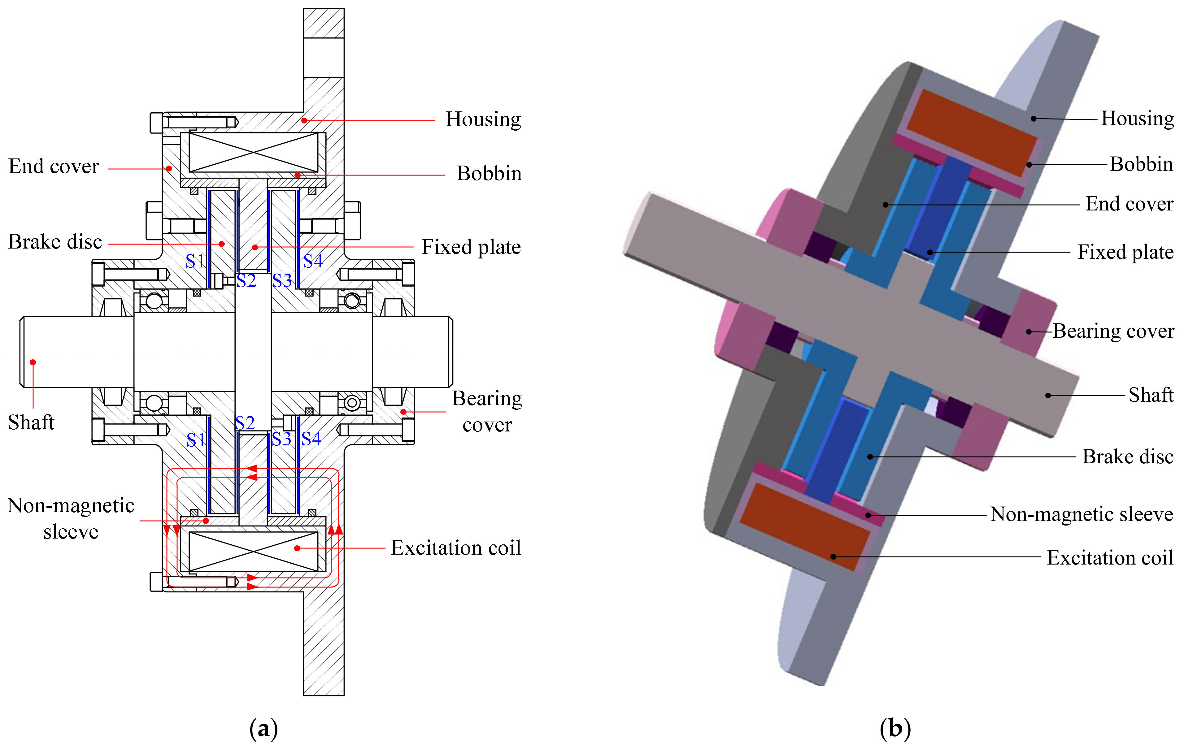
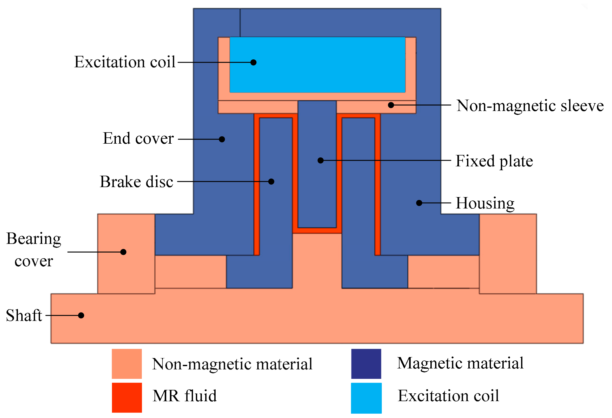
2.1. Working Principle and Structural Design

The MR brake achieves braking through the shearing effect of MR fluid in the magnetic field. Generally, the factors that have a greater impact on the braking effect are the magnetic flux density and the length of the effective damping gap. Therefore, the MR brake with the double brake disc shown in Figure 1 is designed, which reasonably extends the length of the effective damping gap by increasing the number of brake discs and increasing the braking torque while ensuring a compact overall structure. The MR brake is mainly composed of end cover, housing, brake discs, fixed plate, shaft, non-magnetic sleeves, bobbin, excitation coil, etc. The brake disc and the shaft are connected by screws. The end cover, shaft, non-magnetic sleeve, and bobbin are made of stainless-steel non-magnetic material, and the other parts are made of No.10 steel magnetic material.
For disc-type MR brake, the output braking torque will increase with the increase in the numbers of brake discs, but in actual working conditions too many brake discs will make the brake structure more complex and increase volume size. Therefore, the proposed MR brake adopts a common double brake disc structure. As shown in Figure 1, the structure of the double brake disc increases the length of the effective damping gap in the brake. The traditional single disc MR brake generally has two radial flow damping gaps, while the double disc structure meanders the damping gap into four effective radial flow damping gaps. Since the bobbin is made of non-magnetic material, the utilization rate of the magnetic flux lines can be greatly increased, and the magnetic flux lines can be prevented from forming a closed loop outside the damping gap by adding a non-magnetic sleeve at the radially inner ring of the excitation coil, thereby effectively increasing the magnetic flux density of the MR brake. In general, the smaller the thickness of the effective damping gap, the greater the shear stress generated by the MR fluid, and the better the braking performance. However, because the MR fluid itself contains micro-magnetic particles and carrier fluid, and due to the existence of the oil membrane effect, it is easy to block the fluid flow channel and affect the normal work of the MR brake if the fluid flow gaps are small. Therefore, the thickness of the fluid flow channel of the proposed MR brake is set as 1 mm. The maximum diameter and axial length of the MR brake are 130 mm and 60 mm, respectively.
When the MR brake is working, the required DC is applied into the excitation coil. Due to the electromagnetic effect, an induced magnetic field will be generated at the fluid flow channel. The magnetic flux lines are guided inside the brake to pass through the end cover, effective damping gap S1, left brake disc, the effective damping gap S2 and reach the fixed plate, and then vertically pass through the effective damping gap S3, the right brake disc, the effective damping gap S4, and finally form a closed magnetic flux line loop through the housing. Through real-time control of the applied current, the magnetic flux density in the MR brake can be changed, and the stepless adjustment of the braking torque can be achieved according to the actual working conditions.

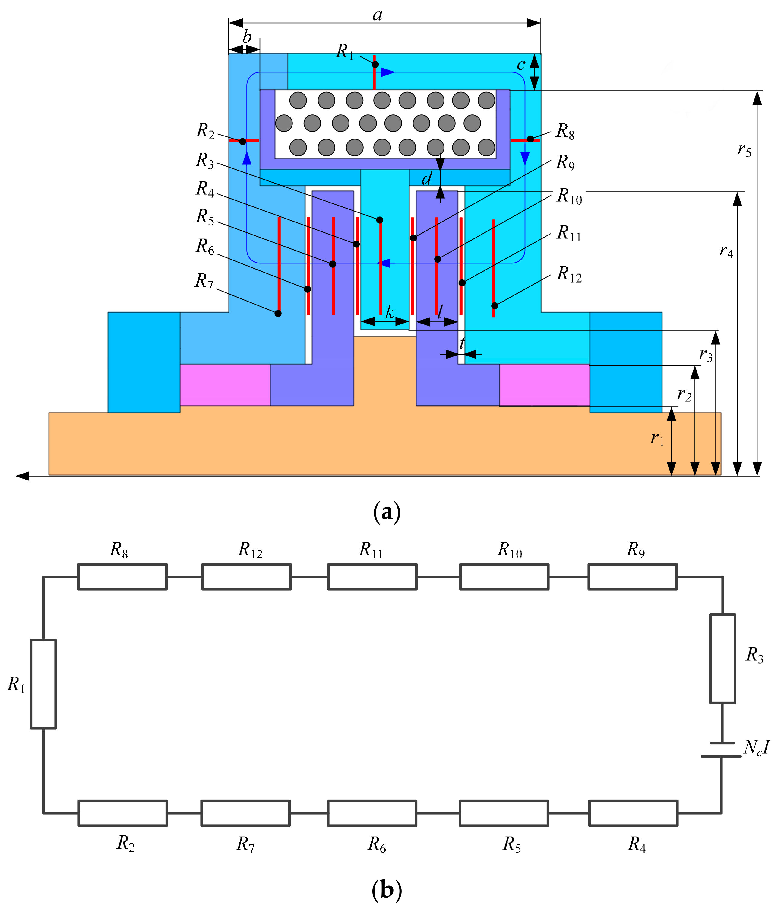
2.2. Magnetic Circuit Analysis of the Proposed MR Brake

In order to simplify the analysis process, the housing outer ring fixing frame is ignored, and the MR brake is regarded as an axisymmetric structure. Figure 2 shows the magnetic circuit of the MR brake. The magnetic circuit including the excitation coil was simplified to a series magnetic circuit so as to simplify analysis.
Analyzed by Kirchhoff’s law of the magnetic circuit, the magneto-motive force can be expressed as:
F = N c I = c H d l = i = 1 12 H i l i
where F is the magneto-motive force, Nc is the number of coil turns, I is the applied current in the excitation coil, Hi is the magnetic field intensity, and li is the effective length of the magnetic circuit.
The magnetic flux perpendicular to a certain section can be expressed as:
Φ = c B d S = B i A i
where Bi is the magnetic flux density, and Ai is the cross-sectional area of the magnetic flux lines perpendicular to the magnetic circuit.
Meanwhile, the magnetic flux density and the magnetic field intensity have the following relationship:
B i = μ 0 μ i H i
where μ0 is the absolute permeability of the air, and μi is the relative permeability of each effective part of the magnetic circuit
In a closed magnetic field loop, the magnetic reluctance Ri of each part is:
R i = l i μ 0 μ i A i
The internal effective structure of the brake is symmetrical, ignoring the magnetic flux leakage of the excitation coil, and almost no magnetic flux lines pass through both ends of the end cover and the housing, then the magnetic reluctance R1 of the effective upper part of the housing can be expressed as:
R 1 = a b π ( r 5 + c ) 2 r 5 2 μ 0 μ 1
The magnetic reluctance R2 of the left wing of the end cover and the magnetic reluctance R8 of the right wing of the housing are approximately as follows:
R 2 = R 8 = ln ( r 5 + c / 2 ) ln ( r 4 + t ) 2 π b μ 0 μ 1 + ln ( 2 r 4 + 2 t ) ln ( r 2 + r 4 ) 2 π e μ 0 μ 1
The magnetic reluctance R3 of the fixed plate can be calculated as:
R 3 = k π ( r 4 + t + d ) 2 r 3 2 μ 0 μ 1
The magnetic reluctance R4 and R9 of the radial damping gap S2 and S3 can be denoted as:
R 4 = R 9 = t π ( r 4 2 r 3 2 ) μ 0 μ 2
The magnetic reluctance R5 and R10 of the effective part of the left brake disc and the right brake disc are approximately as follows:
R 5 = R 10 = l π ( r 4 2 r 1 2 ) μ 0 μ 1
The magnetic reluctance R6 and R11 of the radial damping gap S1 and S4 can be regarded as:
R 6 = R 11 = t π ( r 4 2 r 2 2 ) μ 0 μ 2
The magnetic reluctance R7 and R12 of the bottom of the end cover and the housing are approximately as follows:
R 7 = R 12 = e π ( r 4 + t ) 2 r 2 2 μ 0 μ 1
where μ1 = 1000 H·m−1 is the relative permeability of No. 10 steel, and μ2 = 2.5 H·m−1 is the relative permeability of the MR fluid.
Due to the symmetry of the brake structure, the calculation of the total magnetic reluctance can be denoted as:
R total = R 1 + R 3 + 2 ( R 2 + R 4 + R 5 + R 6 + R 7 )
According to Equations (1)–(3), it can be obtained that:
N c I = i = 1 12 B i μ 0 μ i l i = i = 1 12 l i μ 0 μ i A i Φ = i = 1 12 R i Φ
Therefore, according to Equation (13), the magnetic flux density of each part of the MR brake can be defined as:
B i = Φ S i = N c I A i i = 1 12 R i

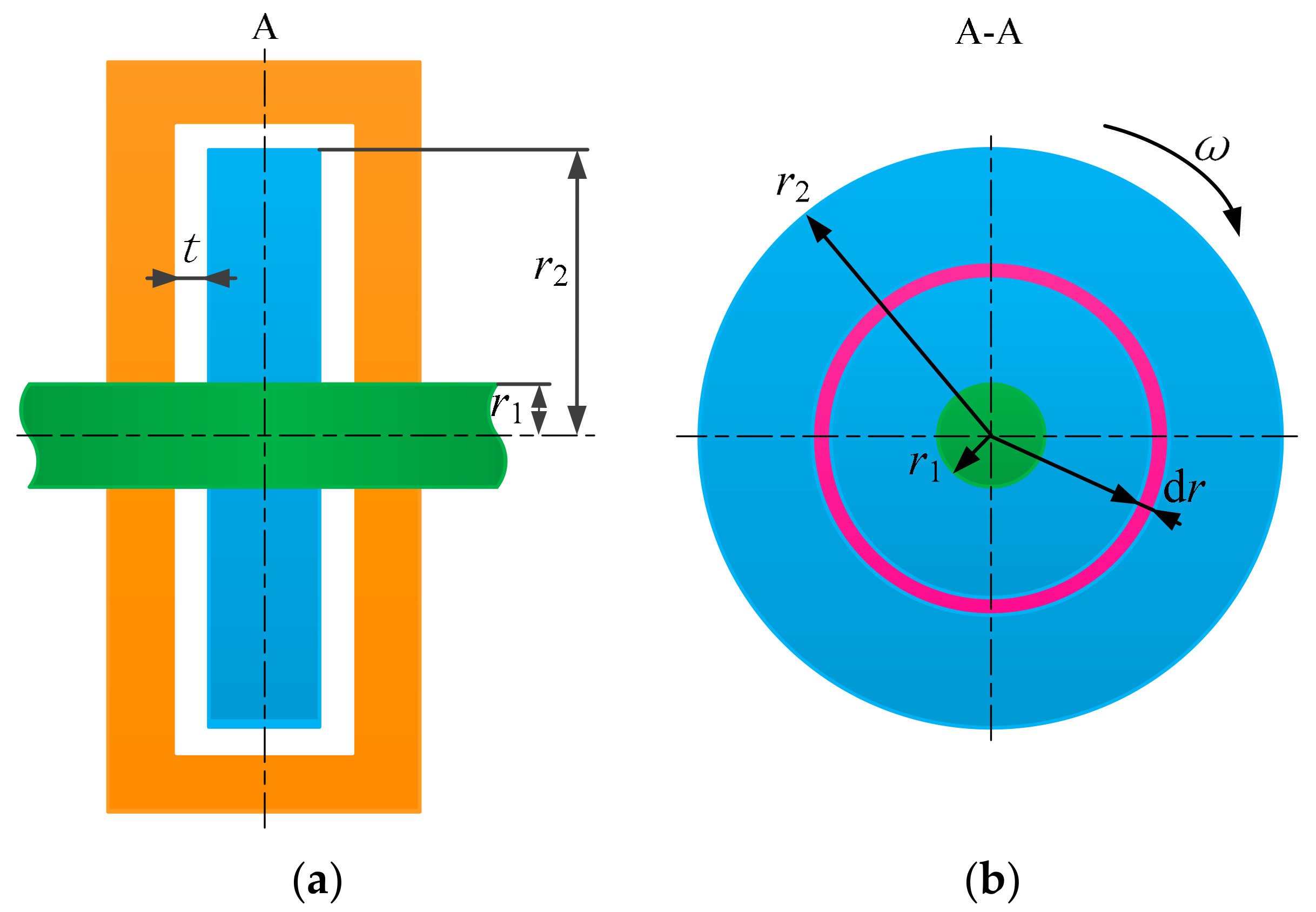
2.3. Mathematical Model of Braking Torque of the Proposed MR Brake

In order to better determine the torque model of the MR brake, it is assumed that the MR fluid cannot be compressed and is evenly distributed in the fluid flow channel. The working mode of the disc-type MR brake is mainly the shear mode, so the Bingham plastic model and the Herschel–Bulkley model are often adopted as the basis for the establishment of the torque model [33,34]. The difference is that the latter considers the influence of the shear rate on the shear stress. The Bingham model is more concise and is suitable for expressing the rheological characteristics of the MR fluid at a medium shear rate. Considering the actual working conditions and to make the model more concise, the constitutive equation of the Bingham model is used in this article; the shear stress equation of MR fluid is shown as:
τ = τ ( B ) sgn ( γ ˙ ) + η γ ˙
where τ is the shear stress of MR fluid, τ(B) is the yield stress of MR fluid changing with the magnetic flux density, η is the zero field viscosity of MR fluid, and γ ˙ is the shear strain rate.
When the magnetic field acts on the MR brake, the output braking torque mainly includes the magnetic torque generated by the yield shear stress τ(B) and the viscous torque produced by the viscosity of the MR fluid. The braking torque of the radial damping gap at the single acting surface of the brake disc is calculated by using the infinitesimal method. Figure 3 shows the axial schematic diagram of the single brake disc.
A ring area dA is selected at the radial damping gap of the brake disc, the force generated at this place is dF, and the braking torque dT generated by this infinitesimal ring area is expressed as:
d T = r d F = r τ d A = 2 π τ r 2 d r
The shear-strain rate at any point in the working area of the brake disc is:
γ ˙ = ω r t
where r is the rotation radius of the optional point, ω is the angular velocity of the shaft, and t is the damping gap thickness of the brake.
From Equations (15)–(17), the braking torque of the MR brake on the ring surface of r1 to r2 can be obtained as:
T 0 = r 1 r 2 2 π r 2 τ d r = 2 π r 1 r 2 r 2 τ ( B ) + η γ ˙ d r = 2 3 π τ ( B ) r 2 3 r 1 3 + π η ω 2 t r 2 4 r 1 4
The total braking torque of the MR brake is:
T = 2 n T 0 = 4 n 3 π τ ( B ) r 2 3 r 1 3 + π η ω n t r 2 4 r 1 4
where n is the number of brake discs.
As the proposed MR brake has two brake discs, the total braking torque is expressed as:
T = 8 3 π τ ( B ) r 2 3 r 1 3 + 2 π η ω t r 2 4 r 1 4
The total braking torque T is composed of TB and Tη. TB is the controllable torque generated by the shear stress of the MR fluid under a magnetic field, and its braking torque changes with the magnetic flux density in the MR fluid. Therefore, it can be adjusted by changing the applied current in the excitation coil. Tη is the torque generated by the viscosity of the MR fluid. Its magnitude is mainly related to the viscosity of the MR fluid and the structural parameters of the MR brake. It accounts for a relatively small part of the total braking torque, so the total braking torque is still regarded as a controllable torque. The total output torque of the brake can be expressed as:
T = T B + T η
Among them:
T B = 8 3 π τ ( B ) r 2 3 r 1 3
T η = 2 π η ω t r 2 4 r 1 4

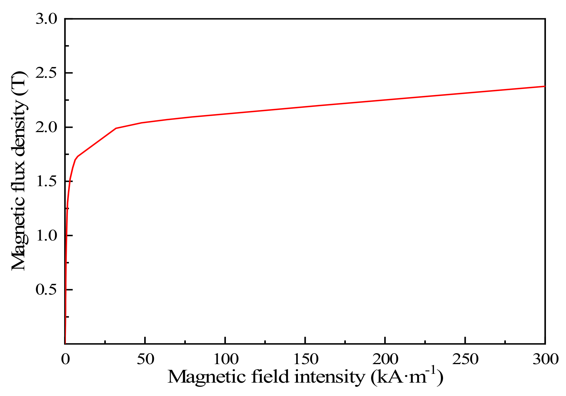
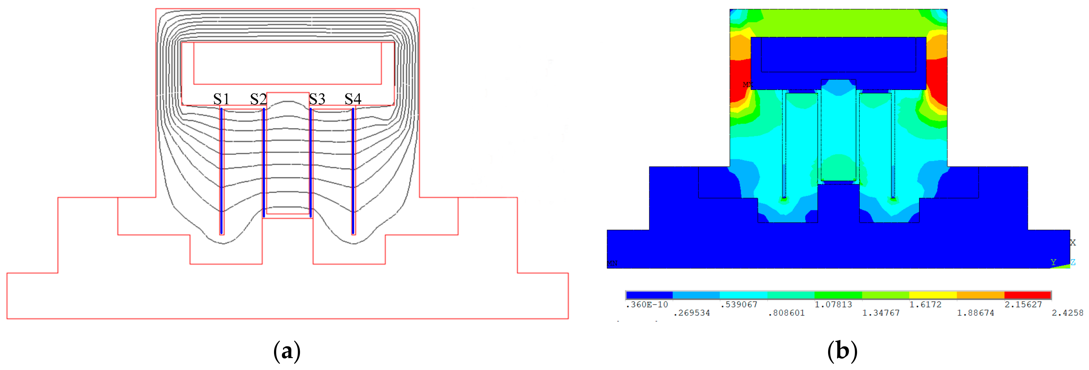
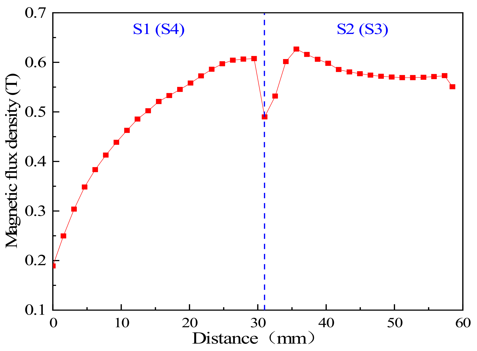
3. Finite Element Simulation of the Proposed MR Brake

In order to simplify the solution process, the instantaneous change of the applied current and the small eddy current generated when the brake disc rotates in the magnetic field are ignored. Only the static magnetic field analysis is needed, that is, the steady-state analysis of the magnetic field of the brake is carried out.
By using the guiding effect of the magnetic and non-magnetic materials on the magnetic flux lines, the magnetic flux lines in the brake are distributed perpendicular to the liquid flow channel as much as possible, which improves the utilization rate of the limited magnetic field. After the structural parameters of the brake are determined, the output braking torque is mainly affected by the magnetic flux density at the effective damping gap. Therefore, to test the braking performance of the MR brake, it is necessary to conduct a finite element analysis of the electromagnetic field inside the MR brake.
Figure 4 shows the magnetization characteristic curve of No. 10 steel. From the BH curve, it can be seen that its hysteresis performance is better when the magnetic field intensity changes within 0–50 kA·m−1. Moreover, the manufacturing cost of No. 10 steel is relatively low, and the processing performance is good, so it is chosen as the magnetic material.
The MRF-J01T MR fluid developed by Chongqing Materials Research Institute in China is used in the MR brake. The related performance of this type of MR fluid is exhibited in Figure 5. The nonlinear relationship between the magnetic flux density and the shear stress is fitted with a cubic polynomial using the Least Square Method [9], and the relationship between the dynamic shear yield stress and magnetic flux density at the effective damping gap is obtained as follows:
τ y = a 1 B 3 + a 2 B 2 + a 3 B + a 4
where a1, a2, a3 and a4 are polynomial fitting coefficients, here, a1 = −984.27 kPa·T−3, a2 = 865.39 kPa·T−2, a3 = −48.46 kPa·T−1, and a4 = 0.02 kPa.
To examine the torque performance of the MR brake, ANSYS software was used to conduct a two-dimensional static magnetic field analysis, which is shown in Figure 6. As the MR brake is an axisymmetric structure, under the premise of ensuring the accuracy of the simulation, selecting 1/2 of the cross section can simplify the calculations.
Figure 7 shows the magnetic circuit simulation results of the MR brake when the applied current is 1.0 A. By adding a non-magnetic material near the excitation coil, more magnetic flux lines pass through the brake disc to form a closed loop, which effectively improves the utilization rate of magnetic field. It can be seen from Figure 7a that the distribution of magnetic flux lines are distributed as expected in the brake, and most of them can pass through the four effective damping gaps vertically, which verifies the correctness and rationality of the structural design and material selection. Figure 7b is the magnetic flux density distribution diagram of the brake. It can be seen that the magnetic flux density at the effective damping gap can be well distributed. When the applied current is 1 A, the maximum magnetic flux density is about 0.63 T, and the average magnetic flux density is about 0.52 T, which is consistent with the distribution law of the magnetic flux lines diagram.
Figure 8 shows the magnetic flux density varying with the path of the flow channel at the applied current of 1.0 A. Since the internal effective structure of the MR brake is symmetrical about the central axis, the magnetic flux density at effective damping gap S1 and S4, as well as S2 and S3, is close to the same. The magnetic flux density at the beginning of the damping gap S1 and S4 is relatively small, mainly due to the material factors of the brake disc, which causes partial magnetic flux leakage. As the path increases, the effective damping gap is closer to the excitation coil, the distribution of the magnetic flux lines is relatively dense, and magnetic flux density gradually increases. At the end close to the axial flow channel, the magnetic flux density decreases slightly. The magnetic flux density at the damping gap S2 and S3 also varies at the beginning and the end, but the magnetic flux lines at most positions are more evenly distributed. It can be seen from Figure 8 that most of the magnetic flux density is in a relatively good range, and the magnetic flux lines are used reasonably. When the applied current is 1.0 A, the average magnetic flux density of damping gap S1 and S4 is about 0.48 T, and the average magnetic flux density of S2 and S3 is about 0.56 T.
Figure 9 shows the change of the average magnetic flux density with the varied applied current. It can be seen that the average magnetic flux density increases significantly when the current varies within 0–1.2 A. After the applied current exceeds 1.2 A, the magnetic field intensity in the MR brake tends to saturation, and its growth rate is relatively slow.
Figure 10 shows the braking torque varying with the applied current at the rotation speed of 400 r·min−1, and the overall trend of braking torque increases with the applied current. When the current increases within 0–1.2 A, it can be seen that the average magnetic flux density at the effective damping gap increases significantly, so the braking torque also increases rapidly. When the current changes from 1.2 A to 2.0 A, the braking torque increases more slowly, and the increase amplitude is not large. When the current approaches 2 A, the braking performance hardly improves, mainly due to the average magnetic flux density not increasing significantly with the current in this interval. In addition, the shear stress almost reaches saturation under this magnetic flux density, so that the braking performance hardly improves with the increase in current. It can be concluded that the maximum braking torque is about 18.15 N·m.

4. Test and Analysis of Braking Torque Performance Characteristics

4.1. Prototype of Proposed MR Brake and Test Rig Setup

According to the structure of the proposed MR brake, the prototype of the MR brake with the double-brake disc was fabricated, which is shown in Figure 11. To provide a greater braking torque and reasonably utilize the internal space of the brake, the number of turns of the excitation coil is 700.
Figure 12 is the torque performance test rig for the MR brake. The torque performance test rig consists of two parts, that is, the motor drive system and the torque performance acquisition system. Among them, the motor drive system is mainly composed of triple-phase asynchronous motor, frequency converter, the developed MR brake, torque and rotational speed sensor (the maximum measured torque is 200 N·m), and other parts. The torque performance acquisition system uses the NI-USB-6210 multi-function acquisition board to obtain the torque performance voltage signal and filters the electrical signal through the computer’s LabVIEW software, and finally processes the experimental data of the speed and torque of the MR brake. The test process is as follows: the motor speed is adjusted through the frequency converter so that the brake is driven to rotate at a certain speed; torque performance is obtained by torque and rotational speed sensor; performance parameters through the data acquisition system are recorded and uploaded.

4.2. Experimental Analysis of Braking Torque Performance

In the experiment, the current adjustment range is 0–2 A, and the range of the rotation speed is 200–600 r·min−1. Figure 13 shows the braking torque varying with the applied current. It can be seen that with the increase in the applied current, the braking torque increases in almost the same trend. When the current changes within 0–1.6 A, the increasing rate is relatively large, and the change trend is obvious. However, when the current increases within 1.6–2.0 A, the output torque tends to be flat since the internal magnetic field of the brake is almost saturated, which is less affected by the applied current. The experimental results illustrate that the maximum braking torque can reach 18.29 N·m when the applied current is 2.0 A and the rotational speed is 600 r·min−1.
Figure 14 shows the comparison between the simulated results and the experimental results of the MR brake at the speed of 400 n·min−1. The simulated braking torque in the zero-field state is 1.33 N·m, and the experimental value is 2.18 N·m at the applied current of 0 A. It is mainly due to the friction between the rotating parts of the brake that the experimental torque value is greater than the theoretical value. When the current continues to increase within a certain range, the experimental braking torque is still greater than the simulated one, but the increasing trend decreases. It can be seen that the simulated braking torque is greater than the experimental value when the current reaches about 0.65 A. The main reason is that the magnetic flux leakage phenomenon and coil heating are ignored, and the Bingham model expression does not take into account the shear thinning phenomenon at the simulation process, which leads to the measured torque value being slightly smaller than the simulated value. When the applied current is 2.0 A, the experimental value is almost close to the simulated value, which is about 18.15 N·m. The experimental curve is consistent with the overall trend of the simulation curve, indicating that the established braking torque model and magnetic field simulation can better express the actual braking performance. It is reflected from the side that the magnetic field simulation of the brake plays an important reference role in the overall experimental design.
Figure 15 shows the changes of braking torque under different currents and speeds. It can be seen that the braking torque increases from 2 N·m to 18 N·m with the applied current, and the adjustable range of braking torque is relatively wide. Under the same applied current, the braking torque increases slightly with the rotational speed, and the rising trend is small. The torque mathematical model shows that the speed has no effect on the magnetic induced torque and has a certain effect on the viscous induced torque. However, the viscous-induced torque accounts for a small proportion of the total braking torque, so the braking torque does not increase much with the increase in rotational speed. This manifests that the MR brake has good constant torque characteristics and is suitable for the application of stable braking or deceleration buffer under various rotational speed conditions.
Two modes of loading and unloading are adopted for the applied current of the MR brake. First, the current is gradually loaded from 0 A to 2.0 A with an interval of 0.2 A, and then the current is gradually reduced from 2.0 A to 0 A by the unloading input mode. Figure 16 shows the hysteresis curve of the braking torque with the current when the speed is 400 r·min−1. It can be seen that under the same rotational speed and the same applied current state, the braking torque in the unloaded state is slightly larger than the torque in the loaded state. The hysteresis phenomenon of the torque curve under the two input states is mainly due to the hysteresis characteristic of the magnetic material when the magnetic flux density changes [35,36]. The larger the distance between the torque curves in the two states, the more hysteresis loss of the magnetic material. In the two opposite loading modes, the torque difference of the MR brake under the same current is small, so the hysteresis characteristic is ideal.

5. Conclusions

An MR brake with a double brake disc was designed and fabricated. The purpose of improving braking performance was achieved by increasing the number of brake discs and reasonably distributing the magnetic materials of the brake structures. The torque mathematical model was established, and the electromagnetic field simulation analysis was also carried out using finite element software. The simulation results manifest that the maximum braking torque reaches 18.15 N·m at a rotational speed of 400 r·min−1.
A performance test rig was setup to investigate the braking performance of the proposed MR brake. The braking performance under different applied currents was tested, and the experimental results show that the maximum braking torque can reach 18.01 N·m and the torque–volume ratio is 22.61 kN·m−2 when the rotational speed is 400 r·min−1, which meets the design requirements, and its experimental value is basically the same as the simulation result. The torque–volume ratio of the designed brake is higher than that of most disc-type MR brakes. Furthermore, different rotational speeds have almost no effect on the braking performance under the fixed applied current, and this characteristic greatly reduces the design difficulty of control strategy of the MR brake and broadens its application fields. The developed MR brake can be used in a variety of medium and low torque braking situations, such as scissor seat suspension for automobile, rehabilitation equipment and machining applications.

Author Contributions

G.H. developed the MR brake and revised the paper; L.W. conducted experimental research and wrote the first draft. L.L. conducted theoretical analysis and built the performance test rig. All authors have read and agreed to the published version of the manuscript.

Funding

This research was funded by the National Natural Science Foundation of China, grant number 51765016.

Conflicts of Interest

The authors declare no conflict of interest.

References

  1. Kumar, J.S.; Paul, P.S.; Raghunathan, G.; Alex, D.G. A review of challenges and solutions in the preparation and use of magnetorheological fluids. Int. J. Mech. Mater. Eng. 2019, 14, 1–18. [Google Scholar] [CrossRef]
  2. Jolly, M.R.; Bender, J.W.; Carlson, J.D. Properties and applications of commercial magnetorheological fluids. J. Intel. Mater. Syst. Struct. 1999, 10, 5–13. [Google Scholar] [CrossRef]
  3. Heo, Y.H.; Choi, D.; Yun, I.; Kim, S. A tiny haptic knob based on magnetorheological fluids. Appl. Sci. 2020, 10, 5118–5129. [Google Scholar] [CrossRef]
  4. Li, D.D.; Keogh, D.F.; Huang, K.; Chan, Q.N.; Yuen, A.C.Y.; Menictas, C.; Timchenko, V.; Yeoh, G.H. Modeling the response of magnetorheological fluid dampers under seismic conditions. Appl. Sci. 2019, 9, 4189–4204. [Google Scholar] [CrossRef] [Green Version]
  5. Zhao, D.; Shi, X.X.; Liu, S.G.; Wang, F.H. Theoretical and experimental investigation on wave propagation in the periodic impedance layered structure modulated by magnetorheological fluid. J. Intell. Mater. Syst. Struct. 2020, 31, 882–896. [Google Scholar] [CrossRef]
  6. Kordonsky, W.I. Magnetorheological effect as a base of new devices and technologies. J. Magn. Magn. Mater. 1993, 122, 395–398. [Google Scholar] [CrossRef]
  7. Blake, J.; Gurocak, H.B. Haptic glove with MR brakes for virtual reality. IEEE/ASME Trans. Mech. 2009, 14, 606–615. [Google Scholar] [CrossRef]
  8. Qin, H.; Song, A.; Mo, Y. A hybrid actuator with hollowed multi-drum magnetorheological brake and direct-current micromotor for hysteresis compensation. J. Intel. Mat. Syst. Struct. 2019, 30, 1–12. [Google Scholar] [CrossRef]
  9. Hu, G.; Zhang, J.; Zhong, F.; Yu, L. Performance evaluation of an improved radial magnetorheological valve and its application in the valve controlled cylinder system. Smart Mater. Struct. 2019, 28, 047003. [Google Scholar] [CrossRef]
  10. Keshav, M.; Bhagyarajan, A.; Chandramohan, S. Regression models for magnetic flux density using DoE techniques and geometric optimization of MR valve. Smart Mater. Struct. 2019, 28, 075008. [Google Scholar] [CrossRef]
  11. Kim, B.; Yoon, D.; Kim, G.; Choi, S.; Tan, A.S.; Sattel, T. Design of a novel magnetorheological damper adaptable to low and high stroke velocity of vehicle suspension system. Appl. Sci. 2020, 10, 5586–5602. [Google Scholar] [CrossRef]
  12. Bai, X.; Hu, W.; Wereley, N.M. Magnetorheological damper utilizing an inner bypass for ground vehicle suspensions. IEEE T. Magn. 2013, 4, 3422–3425. [Google Scholar] [CrossRef]
  13. Diep, B.T.; Nguyen, N.D.; Tran, T.T.; Nguyen, Q.H. Design and experimental validation of a 3-DOF force feedback system featuring spherical manipulator and magnetorheological actuators. Actuators 2020, 9, 19–39. [Google Scholar] [CrossRef] [Green Version]
  14. Qin, H.; Song, A.; Mo, Y. Performance evaluation of a hollowed multi-drum magnetorheological brake based on finite element analysis considering hollow casing radius. IEEE Access 2019, 7, 96070–96078. [Google Scholar] [CrossRef]
  15. Rizzo, R.; Musolino, A.; Bucchi, F.; Forte, P.; Frendo, F. Magnetic FEM design and experimental validation of an innovative fail-safe magnetorheological clutch excited by permanent magnets. IEEE Trans. Energy Conver. 2014, 29, 628–640. [Google Scholar] [CrossRef] [Green Version]
  16. Xu, J.; Liu, Y.; Chen, J.; Li, Y.; Xu, L.; Peng, C.; Chen, S.; Liu, J.; Xu, C.; Cheng, G.; et al. A multi-mode rehabilitation robot with magnetorheological actuators based on human motion intention estimation. IEEE Trans. Neur. Sys. Reh. 2019, 27, 2216–2228. [Google Scholar] [CrossRef]
  17. Avraam, M.; Horodinca, M.; Romanescu, I.; Preumont, A. Computer controlled rotational MR-brake for wrist rehabilitation device. J. Intel. Mater. Syst. Struct. 2010, 21, 1543–1557. [Google Scholar] [CrossRef]
  18. Wang, D.; Wang, Y.; Pang, J.; Wang, Z.; Zi, B. Development and control of an MR brake- based passive force feedback data glove. IEEE Access 2019, 7, 172477–172488. [Google Scholar] [CrossRef]
  19. Wang, N.; Liu, X.; Królczyk, G.; Li, Z.; Li, W. Effect of temperature on the transmission characteristics of high-torque magnetorheological brakes. Smart Mater. Struct. 2019, 28, 057002. [Google Scholar] [CrossRef]
  20. Shiao, Y.; Nguyen, Q. Torque enhancement for a new magnetorheological brake. Procedia Eng. 2014, 76, 12–23. [Google Scholar] [CrossRef] [Green Version]
  21. Wang, D.M.; Hou, Y.F.; Tian, Z.Z. A novel high-torque magnetorheological brake with a water cooling method for heat dissipation. Smart mater. Struct. 2013, 22, 025019. [Google Scholar] [CrossRef]
  22. Wang, N.; Liu, X.; Sun, S.; Królczyk, G.; Li, Z.; Li, W. Microscopic characteristics of magnetorheological fluids subjected to magnetic fields. J. Magn. Magn. Mater. 2020, 501, 166443. [Google Scholar] [CrossRef]
  23. Patel, S.R.; Patel, D.M.; Upadhyay, R.V. Performance enhancement of MR brake using flake-shaped iron-particle–based magnetorheological fluid. J. Test. Eval. 2020, 48, 2396–2411. [Google Scholar] [CrossRef]
  24. Nam, T.H.; Ahn, K.K. A new structure of a magnetorheological brake with the waveform boundary of a rotary disk. Smart Mater. Struct. 2009, 18, 115029. [Google Scholar] [CrossRef]
  25. Qin, H.; Song, A.; Zeng, X.; Hu, S. Design and evaluation of a small-scale multi-drum magnetorheological brake. J. Intel. Mat. Syst. Struct. 2018, 29, 2607–2618. [Google Scholar] [CrossRef]
  26. Liu, B.; Li, W.; Kosasih, P.B.; Zhang, X. Development of an MR-brake-based haptic device. Smart Mater. Struct. 2006, 15, 1960. [Google Scholar] [CrossRef]
  27. Wang, S.; Song, W.; Li, H.; Wang, N. Modeling and multi-field simulation analysis of a multi-cylindrical magneto-rheological brake. Int. J. Appl. Electrom. Mech. 2018, 57, 399–414. [Google Scholar] [CrossRef]
  28. Hu, G.; Wu, L.; Li, L.; Yu, L. Performance analysis of rotary magnetorheological brake with multiple fluid flow channels. IEEE Access 2020, 8, 173323–173335. [Google Scholar] [CrossRef]
  29. Binyet, E.M.; Chang, J. Magnetohydrodynamics modelling of a permanent magnets activated MRF clutch–brake. Microsyst. Technol. 2020, 26, 3451–3457. [Google Scholar] [CrossRef]
  30. Mousavi, S.H.; Sayyaadi, H. Optimization and testing of a new prototype hybrid MR brake with arc form surface as a prosthetic knee. IEEE/ASME Trans. Mech. 2018, 23, 1204–1214. [Google Scholar] [CrossRef]
  31. Shiao, Y.; Ngoc, N.A.; Lai, C. Optimal design of a new multipole bilayer magnetorheological brake. Smart Mater. Struct. 2016, 25, 115015. [Google Scholar] [CrossRef]
  32. Shiao, Y.; Nguyen, Q.A. Development of a multi-pole magnetorheological brake. Smart Mater. Struct. 2013, 22, 065008. [Google Scholar] [CrossRef]
  33. Zhang, Y.; Li, D.; Cui, H.; Yang, J. A new modified model for the rheological properties of magnetorheological fluids based on different magnetic field. J. Magn. Magn. Mater. 2020, 500, 166377. [Google Scholar] [CrossRef]
  34. Raul-Alexandru, S.; Daniela, S.R.; Sebastian, M.; Vékás, L. Magnetorheological Fluids Flow Modelling Used in A Magnetorheological Brake Configuration. In Proceedings of the 2019 International Conference on Energy and Environment, Timisoara, Romania, 17–18 October 2019; pp. 403–407. [Google Scholar]
  35. Bai, X.; Chen, P. On the Hysteresis mechanism of magnetorheological fluids. Front. Mater. 2019, 6, 36–44. [Google Scholar] [CrossRef] [Green Version]
  36. Bai, X.; Cai, F.; Chen, P. Resistor-capacitor (RC) operator-based hysteresis model for magnetorheological (MR) dampers. Mech. Syst. Signal Pr. 2019, 117, 157–169. [Google Scholar] [CrossRef]
Figure 1. Structure diagram of magnetorheological (MR) brake. (a) Structure schematic and (b) three-dimensional model.
Actuators 10 00023 g001
Figure 2. Diagram of magnetic circuit. (a) Control sections and (b) equivalent circuit.
Actuators 10 00023 g002
Figure 3. Schematic diagram of brake disc. (a) Front view and (b) cross-sectional view.
Actuators 10 00023 g003
Figure 4. BH curve of No. 10 steel.
Actuators 10 00023 g004
Figure 5. τy–B curve of MRF-J01T.
Actuators 10 00023 g005
Figure 6. Material distribution for simulation modeling.
Actuators 10 00023 g006
Figure 7. Magnetic circuit simulation results. (a) Distribution of magnetic flux lines and (b) distribution of magnetic flux density.
Actuators 10 00023 g007
Figure 8. Variation of magnetic flux density along paths.
Actuators 10 00023 g008
Figure 9. Variation of average magnetic flux density with current.
Actuators 10 00023 g009
Figure 10. Simulation results of braking torque with current.
Actuators 10 00023 g010
Figure 11. Prototypes of MR brake. (a) Components and (b) prototype.
Actuators 10 00023 g011
Figure 12. Experimental test rig. (a) Schematic diagram and (b) test rig. (1) Power supply, (2) MR brake, (3) coupling, (4) speed torque sensor, (5) acquisition board, (6) three-phase asynchronous AC motor, (7) frequency converter, (8) computer.
Actuators 10 00023 g012
Figure 13. Variation of experimental braking torque with current and rotational speed.
Actuators 10 00023 g013
Figure 14. Variation of simulated and experimental braking torque.
Actuators 10 00023 g014
Figure 15. Dynamic variation of braking torque under different currents and rotational speeds.
Actuators 10 00023 g015
Figure 16. Hysteresis curve of braking torque.
Actuators 10 00023 g016
Publisher’s Note: MDPI stays neutral with regard to jurisdictional claims in published maps and institutional affiliations.

