Abstract
The paper presents a joint experimental and numerical characterization of double-orifice synthetic jet actuators for flow control. Hot-wire measurements of the flow field generated by the device into a quiescent air environment were collected. The actuation frequency was systematically varied to obtain the frequency response of the actuator; its coupled resonance frequencies were detected and the velocity amplitude was measured. Direct numerical simulations (DNS) of the flow field generated by the device were subsequently carried out at the actuation frequency maximizing the jet output. The results of a fine-meshed parametric analysis are outlined to discuss the effect of the distance between the orifices: time-averaged flow fields show that an intense jet interaction occurs for small values of the orifice spacing-to-diameter ratio; phase-averaged velocity and turbulent kinetic energy distributions allow to describe the vortex motion and merging. A novel classification of the main regions of dual synthetic jets is proposed, based on the time- and phase-averaged flow behaviour both in the near field, where two distinct jets converge, and in the far field, where an unique jet is detected. The use of three-dimensional DNS also allows to investigate the vortex merging for low values of the jet spacing. The work is intended to provide guidelines for the design of synthetic jet arrays for separation control and impinging configurations.
1. Introduction
The use of synthetic jet (SJ) actuators for flow control has become widespread during the last years. Their application field is nowadays very wide, including flow separation control [1], optimization of the aerodynamic forces of lifting surfaces on aircraft [2] and wind energy systems [3], jet cooling [4] and many other activities. The rise in popularity of synthetic jet actuators has been driven by the fact that they are able to produce global changes to an incoming flow with low power consumption and reduced sizes [5].
Generally, synthetic jets are generated by arrays or multi-orifice devices, in order to maximize their efficiency in impinging configurations or to cover extended regions for separation control purposes [6,7]. The flow field generated by these devices and their heat transfer performance are dramatically influenced by the presence of adjacent jets, which can interact and merge, thus affecting their control authority. For this reason, research activities on multi-orifice actuators in quiescent conditions appeared as a compulsory step before introducing them in more complex environments.
The application of multi-orifice and multi-slot actuators in practical situations is well established in literature, starting from the seminal work of Smith and Glezer [8] on a double-slotted actuator. One of the key reasons which led the researchers to investigate this configuration is its higher cooling performance with respect to a single, centered orifice. The works by Chaudhari et al. [9] and Mangate et al. [10] first investigated this feature: they designed an actuator with a resonant cavity connected to the external environment by means of a set of circular orifices, constituted by a central one, which is surrounded by satellite holes. Their experimental measurements allowed to state that this solution is able to achieve a higher heat dissipation if compared with a single hole device, even if a plug central orifice is considered.
Introducing a phase difference between the jets has been found to further enhance their thermal efficiency: Luo et al. [11] conceived an innovative synthetic jet device, where a resonant cavity is split by a wall on which two piezo-electric elements are glued, thus creating two jets in opposing phase. This actuator was recently used for the control of spray cooling systems by He et al. [12]. The same goal, obviously, can be accomplished by using jets issuing from twin, independent cavities, as in Alimohammadi et al. [13] and Berk et al. [14]. This allowed to exploit a continuous range of phase differences between the jets, which can be fixed between 0 and to maximize a relevant performance index.
Besides, a smaller number of research activities involved multiple synthetic jets issuing in phase into a free, quiescent environment. The first study of this kind was carried out by Watson et al. [15], who investigated experimentally the effects of the jet exit area and spacing using smoke and laser visualization techniques. Implications of the use of adjacent synthetic jets to control an incoming crossflow were subsequently discussed by the same group [16]. More recently, Riazi and Ahmed performed numerical simulations of the external field generated by a double-orifice synthetic jet actuator [17]. Its behaviour was first compared with an equivalent, single-orifice one, then the effects of varying the orifice diameter and the jet spacing on the vortex coalescence were investigated. They found a threshold value of (where is the orifice spacing and d the orifice diameter) for vortex interaction, which depends on the dimensionless stroke length of the actuator. However, their analysis was restricted to very low Reynolds numbers (indeed, the flow is laminar), which rarely occurs in practical SJ applications.
Chiatto et al. [18] carried out a joint numerical, experimental and analytical lumped element model (LEM) investigation. They have been able to describe the effect of the main actuator characteristics (actuation frequency, cavity geometry and mechanical properties) on the jet output. Ceglia et al. [19] performed an experimental study, using hot-wire anemometry (HWA) and particle image velocimetry (PIV) to investigate the external flow behavior of an array of slotted synthetic jets in quiescent condition. Their analysis considered both the time-averaged flow characteristics, including jet spreading, axis switching and streamwise velocity decay, and phase-averaged velocity data to discuss the vortex organization and trajectory. The same device was also numerically investigated by Palumbo et al. [20]. Kim et al. [21] analyzed the effect of dimensionless orifice spacing and stroke length on the jet interaction in double-orifice synthetic jets, using phase-locked PIV to obtain time- and phase-averaged flow fields. They invoked previous findings on continuous dual-jet flows to define different flow regions, where the jet trajectories converge and merge in single ones, and investigated their features as a function of the SJ operation parameters.
The present analysis is focused on the practical realization of a double-orifice actuator for flow control. A combined experimental and numerical investigation has been carried out, in order to characterize the actuator performance and detect the main external flow characteristics. A first step of the present study consisted in the actuator design and manufacturing; hot-wire measurements of the flow immediately downstream of the orifice exit plane were collected for different values of the actuation frequency, thus obtaining the frequency response of the device.
Direct Numerical Simulations (DNS) of the actuator under investigation were subsequently performed: while the computational geometry of the cylindrical cavity perfectly matches the experimental one, the orifices position was gradually changed to seek a configuration characterized by strong jet interaction. The innovative aspect of the present work is that, to the authors’ knowledge, no fully three-dimensional representation of the turbulent flow field generated by the synthetic jets in dual-orifice configuration has been obtained so far. As a matter of fact, the additional flow resolution guaranteed by DNS, its intrinsic three-dimensionality and ability of capturing all temporal and spatial scales of the instantaneous, turbulent motion can provide further insights than the previous experimental studies [21] and laminar simulations [17]. It is worth noting that the experimental and the computational methods are basically complementary to each other: the experimental investigation allowed to obtain an overall assessment of the actuator performance (in terms of the relation between the jet output velocity and the actuation frequency), and to detect its resonance frequencies. The numerical simulations have been carried out at the actuation frequency which maximizes the jet averaged velocity, taking advantage of the previous experimental study, and their aim is basically to investigate the dependence of the external flow features on the jet spacing.
The paper is outlined as follows: Section 2 outlines the experimental and numerical methods employed for the present analysis, and the set of the involved actuator parameters. Section 3 regards the frequency response of the device, based on hot-wire experimental measurements, whereas the effect of the orifice spacing on the external flow development is numerically analyzed in Section 4. Conclusions are reported in Section 5, which also includes a brief discussion of future work.
2. Experimental and Numerical Methodology
The present section is devoted to providing information about the experimental and numerical setup employed for the present investigation. A description of the manufactured device and the experimental mock-up is presented in Section 2.1, whereas a description of the numerical tools in given in Section 2.2.
2.1. Experimental Setup and Synthetic Jet Actuator Description
A double-orifice synthetic jet actuator was designed to investigate the features of multi-orifice devices. The actuator was completely assembled in house: it consists of a thin lead zirconate titanate (LZT) piezo-element (realized by PIEZO Inc. and reported as the element (2) in Figure 1), which is glued on the bottom surface of a brass membrane (element (3) in Figure 1) using a two-component silver-filled epoxy resin (EPO-TEK E4110-LV); A circular guide was used to correctly place the piezo-ceramic disk, to have its axis coincident with the actuator one. A sketched view of the main elements of the actuator is provided in Figure 1, which also highlights its correct assembly order and the main connecting elements; the geometrical parameters and mechanical properties of the double-orifice actuator are summarized in Table 1 and Figure 2: a shallow cavity of diameter mm and height mm (element (4) in Figure 1) is connected to the external environment by two cylindrical orifices of length mm and diameter mm (elements (5) in Figure 1).
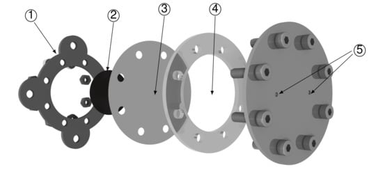
Figure 1.
Exploded view of the double-orifice synthetic actuator, with indication of the main connection elements: support (1), piezo-element (2), shim (3), cylindrical cavity (4), orifices (5).

Table 1.
Geometrical characteristics, mechanical properties and resonance frequencies of the double-orifice synthetic jet actuator. The subfixes and refer to the shim and piezo-element properties.
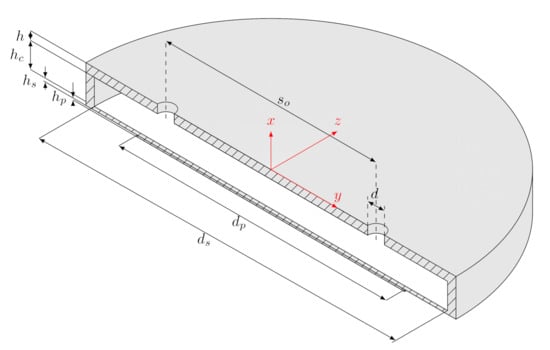
Figure 2.
Sketch of the double-orifice configuration under investigation, with main notation and reference axes.
The piezo-element is deformed as the result of the application of a sinusoidal electrical excitation, generated by a multi-function instrument (Digilent Analog Discovery 2) first, and then amplified by a linear gain amplifier (EPA-104, Piezo Systems). Piezo-electric electrodes are connected to the amplifier, and welded to the LZT disk in order to provide the desired excitation. A peak-to-peak voltage equal to 60 was fixed for all the experiments, whereas the actuation frequency range was preliminarily chosen according to analytical evaluations of the decoupled structural and fluid-dynamic (Helmholtz) resonance frequencies, whose expressions can be found on previous works [22,23]. Further remarks on the selection of the actuation frequency range are given in Section 3, as regards additional information on the physical characteristics of the piezo-ceramic disk, the reader is referred to previous works written by the present authors [22,24], where the same type of piezoceramic disk has been employed and its parameters have been used to build a lumped element model of the actuator.
The frequency response of the actuator and the distribution of its main non-dimensional parameters (described in the following) were obtained by means of experimental measurements of the streamwise velocity component at a location close to the orifice exit (). A constant temperature hot-wire anemometer (Dantec Dynamics MiniCTA), equipped with a 5 m wire probe, was used at this purpose. The measurement device has been preliminary calibrated, as outlined in Appendix B, to obtain a relationship between the output voltage and the measured velocity. The velocity signal was sampled at a 10 kHz rate for over 1000 cycles; an estimation of the experimental uncertainty of the hot-wire data has been made with standard procedures [25]; the uncertainty in the phase-averaged streamwise velocity is found to be less then .
The experimental mock-up used throughout the present work is shown in Figure 3; all tests have been carried out at atmospheric pressure and a constant temperature of 21 C within a unique time window, which made possible to neglect the effect of temperature variations on the hot-wire anemometry calibration curve. The effect of the misalignment between the air flow generated by the actuator and the hot-wire anemometer is not considered as well, as the hot-wire measurements are collected in the near-field region of the jet, within its potential core, where the velocity is orthogonal to the orifice exit plane. This assumption is further corroborated by the numerical simulation in Section 4.1, which also shows that the jets evolve independently for the chosen value of for the experimental actuator (meaning that no jet convergence is detected in this case).
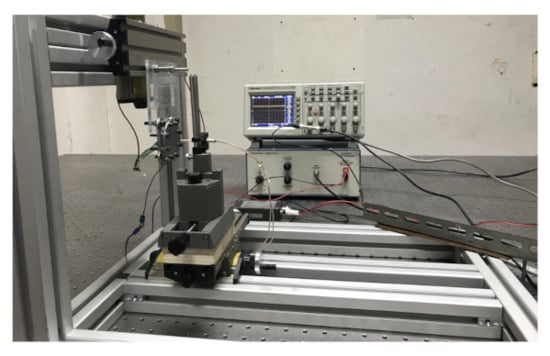
Figure 3.
View of the experimental setup for the hot-wire anemometry measurements.
The primary objective of the experimental campaign was the evaluation of the phase-averaged velocity at the orifice exit , which can be used to obtain an experimental-based definition of the stroke length:
where T is the actuation period. The non-dimensional stroke length is a crucial parameter in determining the synthetic jet performance as it is related by many authors to the jet formation (see [23] for an extensive discussion on this topic). Besides, other important non-dimensional quantities are the jet Reynolds, Stokes and Strouhal numbers, defined in the following Equation (2)
where is the averaged jet blowing velocity. Such parameters exhaustively define the external flow features of a single-cavity, single-orifice actuator; however, in the context of multi-orifice actuators the jet spacing-to-diameter ratio is definitely an additional parameter to be taken into consideration. It is worthwhile noting that the quantities described above are intrinsically area-averaged due to the finite dimension of the hot-wire probe: on the other hand, numerical simulations allow to define another reference velocity
with Reynolds and Strouhal numbers modified accordingly.
2.2. Numerical Model
The numerical investigation relies on fully three-dimensional direct numerical simulations of the flow field generated by the double-orifice actuator in a quiescent environment. A representation of the z-normal symmetry plane of the three-dimensional domain used for the present work is depicted in Figure 4, highlighting the boundary conditions enforced on the external boundaries.
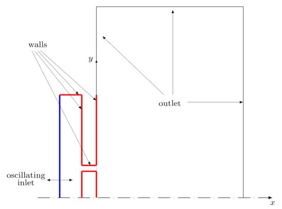
Figure 4.
Numerical setup: slice view of the symmetry plane and summary of the boundary conditions.
The numerical domain includes the actuator cavity, the orifices and an external environment of cylindrical shape; the external domain was designed, after preliminary computations, to be large enough to prevent any dependence of the numerical results on its dimensions. The cavity geometrical parameters (height and diameter) were fixed for all simulations as well as the orifice shape, whereas the orifice distance is systematically varied to investigate its effect on the jet development. The parameter ranges between 5 mm (which, as highlighted in Section 4, satisfies the criterion for vortex interaction by Riazi and Ahmed [17]) and 25 mm, which is the orifice spacing of the manufactured actuator. The latter case constitutes a validation of the numerical setup.
The numerical simulations were carried out using the popular open-source suite OpenFOAM. This code has been widely used in a large variety of fluid-dynamic problems, both in industrial and research activities. The native solver pimpleFoam, based on a finite-volume discretization of the unsteady incompressible Navier-Stokes equations, was chosen. All simulations were carried out in parallel on the CINECA high-performance clusters Marconi and Galileo, using up to 256 processors.
The multi-block, structured numerical meshes used in the present work were built using the native meshing tool blockMesh; the domain decomposition required for the parallel computation was obtained using the parallelization option scotch provided by the OpenFOAM utility decomposePar. Figure 5 represents two zoomed views of the grid in the x-y and y-z planes, next to the orifice exit, for the case: the mesh was clustered in the near field to correctly discretize the actuator geometry and provide good resolution of the high velocity gradients. The total number of cells of the numerical mesh reaches about 4 millions for the finest grid used within the present work; two coarser grids, of about 1 and 2 million grid cells, were also tested.

Figure 5.
Zoomed view of the computational mesh in the x-y plane (left) and y-z plane (right). Case . Only half of the cells are shown for the x-y view.
The temporal discretization used for all computations is based on a order, multi-step backward scheme, whereas the spatial discretization relies on full order centred schemes. The arising pressure linear system is solved using a generalized geometric-algebraic multi-grid (GAMG), with a target tolerance of ; a Gauss-Seidel iterative method with the same tolerance is used for the momentum equation. A constant Courant number is used for all simulations; the flow was initially at rest, then 10 operating cycles were simulated to reach a statistically stationary flow. The averaging process was carried out within the following 40 cycles.
The metal shim is driven at its structural frequency, which is shown to be 1850 Hz in Section 3, for all simulations. The effect of the oscillating motion on the flow within the cavity is modeled using a time-varying Dirichlet condition, enforced at the undisturbed position of the diaphragm. More details on the time and space distributions of the inlet condition are provided in Appendix A; in this context, it is worthwhile remarking that the goals of the analytical approach carried out for the evaluation of the inlet condition were to define a spatial shape close to the actual diaphragm motion and to obtain the correct value of the volumetric flow rate to match the experimental measurements at the jet exit. Moreover, as the oscillating inlet condition mimics the actual wall deformation, no turbulent fluctuations have been introduced on this boundary; the turbulent nature of the flow is the result of the transitional phenomena inside the pipe and in the external environment.
As regards the other velocity boundary conditions, no-slip conditions are enforced on all of the fixed cavity walls, whereas homogeneous Neumann conditions are applied on the side environmental boundaries. The mixed condition inletOutlet is used on top of the external domain, which automatically prevents the possibility of backflow when the instantaneous turbulent flow structures impact against the domain streamwise end. The (differential) pressure is set to zero on the same boundary and the environment sidewalls, as opposed to all the other domain faces where a null normal derivative is imposed.
3. Experimental Evaluation of the Actuator Frequency Response
The frequency response of the device, in the plane, is reported in Figure 6; it was obtained varying the actuation frequency from 0 to 2500 Hz, which corresponds to a Stokes number ranging from 0 to 65. The frequency range is chosen to include both the incompressible actuator behavior (which is obtained for small values of the actuation frequency) [22] and the resonance frequencies. As regards the latter quantities, the structural and Helmholtz uncoupled frequencies have been computed and used to define the experimental operation range: their values are given by Equations (A6) and (4), respectively:
where is the ambient air density, is the heat coefficient ratio and the orifice area. It must be noted that, according to [18], the modified length of the orifice is used for the evaluation of the Helmholtz frequency, and only half of the cavity volume is considered. The values of the uncoupled resonance frequencies are Hz and Hz; as little jet velocity is detected for Hz, the experimental campaign was stopped at this frequency value.
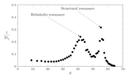
Figure 6.
Frequency response of the manufactured double-orifice actuator: experimental Strouhal number as a function of the Stokes number S. The resonance peaks (modified structural and Helmholtz frequencies) are highlighted.
Note that at low frequencies all the data points tend towards a constant value represented by the incompressible solution, which is the static solution of the equivalent forced damped spring-mass system [23]. Increasing the Stokes number (thus the actuation frequency), higher velocities are retrieved close to the modified Helmholtz () and structural () resonance frequencies, and then the response decreases to zero. For this specific case, the Helmholtz resonance frequency is equal to Hz (), while the structural one is Hz (); this latter has been chosen as the reference case for the numerical simulations reported below.
4. Effect of Orifice Spacing via Direct Numerical Simulation
The direct numerical simulations of the flow generated by the device for different values of the orifice spacing ratio are discussed in the present section. Four spacing values have been considered for the numerical campaign only, namely = 2.5, 3, 3.75, 5, with the additional validation case of , identical to the manufactured device. The validation study is discussed in Section 4.1: the list of the computational cases involved in the present investigation is given in Table 2.
Table 2.
Summary of the numerical cases: V is the validation case, S1–S4 refer to the parametric analysis in terms of the orifice spacing.
All the computational results are shown in terms of time-averaged and phase-averaged velocity fields, defined as in Equation (5):
where is the time-averaged velocity vector field and is the phase-averaged one. The remaining terms on the right-hand side of Equation (5) are the phase-correlated velocity contribution (due to the periodic inlet generated by the actuator) and the actual turbulent fluctuation . As usually done for synthetic jets, it is interesting to investigate the phase-averaged Reynolds stress tensor , which well describes the turbulent behavior of the flow during the actuation cycle. The turbulent kinetic energy associated to this Reynolds stress definition is . Finally, the phase-averaged Q-criterion [26] is used to investigate the development of the vortical structures generated during the ejection phase at the actuator exit.
4.1. Validation of the CFD Setup
A preliminary step of the numerical investigation consisted in validating the CFD setup. For this reason, a preliminary computation was performed for the very same geometry involved in the experimental analysis (with ). The reference quantity used for validation was the phase-averaged streamwise velocity component at the jet exit, where hot-wire measurements are available (, ). A comparison between the CFD results and the experimental data is provided in Figure 7, where three different grids are investigated: it is shown that a good agreement is obtained for the finest grid case, which is also characterized by a quasi-sinusoidal trend.
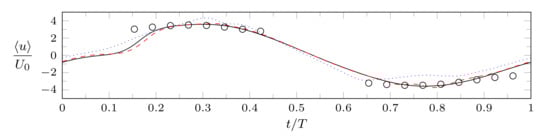
Figure 7.
Comparison between experimental streamwise phase-averaged velocity measurements at the orifice exit plane (circles) and numerical results for different grid sizes: coarse (dotted line), medium (dashed), fine (solid). Validation case, .
Interestingly, one can erroneously state that a phase lag between the actuator forcing and the jet output exists at the beginning of the actuator cycle; in fact, such a behavior can be attributed to the effect of the very high Stokes number of the simulations, which leads to an irregular velocity profile at the jet exit. A closer look to the phase-averaged volumetric flow rate, depicted in Figure 8, reveals that there is no actual phase difference between the diaphragm velocity and the exit flow rate, given that a sinusoidal trend is retrieved for this quantity. Such a behaviour must be expected for the chosen computational setup.
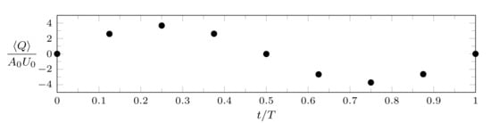
Figure 8.
Phase-averaged distribution of the volumetric flow rate issuing from one orifice. Validation case, , fine grid.
The possible existence of twin jet interaction can be investigated by looking at the time-averaged velocity profiles in Figure 9. It is clear that the jets behave as isolated ones, due to the very high spacing between the orifices. Indeed, the crosswise location of the velocity peaks is basically constant with x, suggesting that the jet trajectories are orthogonal to the exit plane, and a large region of null streamwise velocity is obtained between the jets.
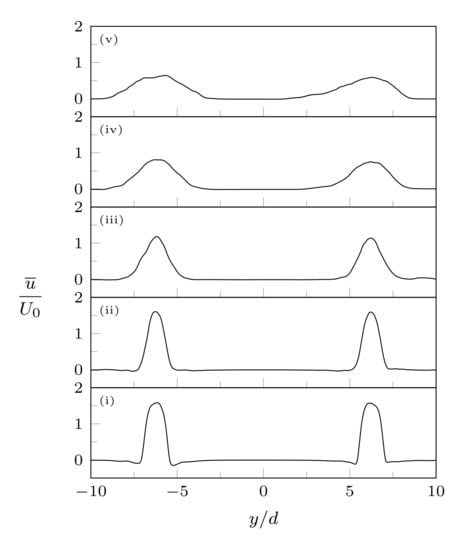
Figure 9.
Crosswise profiles of time-averaged streamwise velocity at streamwise stations (i) , (ii) 2, (iii) 4, (iv) 6, (v) 8.
As a result of the validation study, it can be stated that the numerical setup is capable of reproducing the experimental data, but no jet interaction can be seen for the baseline case mm. Given that the next sections are devoted to investigating possible jet convergence and vortex merging phenomena, this case will not be investigated any further.
4.2. Phase-Averaged Results
A three-dimensional view of the different flow topologies generated for two values is given by Figure 10, which depicts the vortex distribution for and during the ejection phase (). Vortex interaction is clearly visible in the former case, as the vortices move toward the symmetry plane during their motion; the inner parts of the vortex rings basically meet themselves after about 2 cycles. The ring shapes are also affected by the small orifice distance, as the vortices generated in the previous cycle are clearly distorted for the lowest value. In fact, it can be seen that the inner sides of the vortex rings are basically parallel to the actuator exit plane, whereas their outer edges are strongly inclined. The above features cannot be observed for the vortex rings in the case, whose trajectories are roughly parallel to the x axis and their annular shape is preserved during their motion.
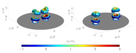
Figure 10.
Isosurfaces of phase-averaged Q-criterion, colored with the streamwise phase-averaged velocity component : , , (left), (right).
Further insights on synthetic jet merging during the actuation cycle can be observed using phase-averaged velocity fields. Figure 11 and Figure 12 depict several contour plots of streamwise velocity and turbulent kinetic energy in the x-y plane at different actuation phases. For simplicity only one orifice is shown, thus exploiting the fact that phase-averaged streamwise fields are symmetric with respect to the x axis. In the case the flow is clearly asymmetric with respect to the orifice axis (), as the jet trajectory is strongly inclined toward the plane. The negative streamwise velocity observed in the inner region is stronger than the external one, as the result of the composition of the velocities induced by the vortex pair. This effect can be easily deduced by the kinetic energy contour plots, which are characterized by a strong asymmetry with respect to the orifice axis as well. In particular, in the near field a strong region of turbulent intensity can be encountered in the external part of the vortex ring; this intense turbulent region rapidly dissipates as the vortices move downstream, whereas the turbulent intensity in the region between the orifices simultaneously increases. For the kinetic energy distribution appears to have only the external peak, meaning that its distribution is matching the one of a single turbulent jet.
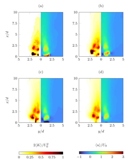
Figure 11.
Contour plots of the phase-averaged turbulent kinetic energy (left half of each plot) and phase-averaged streamwise velocity component (right half of each plot): , , (a) 0.25, (b) 0.5, (c) 0.75, (d) 1.
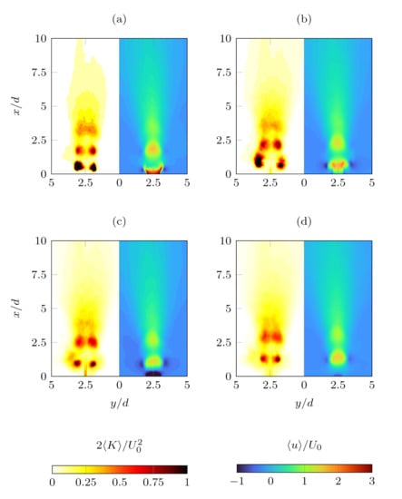
Figure 12.
Contour plots of the phase-averaged turbulent kinetic energy (left half of each plot) and phase-averaged streamwise velocity component (right half of each plot): , , (a) , (b) 0.5, (c) 0.75, (d) 1.
On the other hand, all the features just described are barely visible for the case, suggesting that the vortices dissipate themselves before reaching the plane. However, for the jet is clearly spreading in the y direction, meaning that a possible jet merging can be seen in the far field region due to this effect, rather than due to vortex interaction. However, such a jet coalescence would happen in a region where the jet strength is almost dissipated.
Finally, it is interesting to investigate the phase-averaged streamwise velocity distribution along the x axis, shown in Figure 13. As a matter of fact, the pair of vortex rings generated by the double-orifice device induces a reverse flow region between them, which is clearly visible for the lowest spacing case. This negative streamwise velocity area can be observed during the entire cycle, not only during the suction phase, meaning that an extended, strong time-averaged recirculation region should be expected.
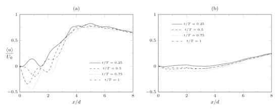
Figure 13.
Distribution along the x axis of the streamwise component of the phase-averaged flow field , for different phases: = 0.25, 0.5, 0.75, 1. (a) , (b) .
Likewise, the highest spacing case is also characterized by the presence of a reverse flow phase-averaged streamwise velocity, whose intensity is smaller than in the above case; the reverse flow is stronger during the suction phase, as for the lower actuator.
In conclusion, the phase-averaged flow field is characterized by the presence of two reverse flow region, one occurring only during the suction phase around the orifice exit and another one lying on the symmetry plane due to the vortex-induced velocity. The latter region reaches a longer streamwise distance from the exit plane than the former (for , ≈2.5d for the reverse flow on the symmetry plane, ≈0.5d for the extremal position of the saddle point), meaning that double-orifice actuators are characterized by the possibility of negative streamwise velocity way beyond the saddle point. This feature must be taken into account for both control and cooling applications.
4.3. Time-Averaged Results
The theory of continuous twin jets has defined two main characteristic points, namely the merging point and the converging point, which can be used to split the time-averaged velocity field into three main regions: a converging region, where a low-speed motion can be observed within the jets, a merging region, where the jets coalesce and the velocity peaks converge toward the spanwise symmetry plane, and the combined region, where the flow behaves as a single jet [27,28]. Operative definitions of the time-averaged streamwise locations and of merging and combined points are the following: is obtained as the streamwise location where the streamwise velocity on the actuator axis is null, whereas is evaluated as the location where the velocity peak is close enough to the centerline one.
It is worth noting that the converging region of continuous slotted jets is characterized by the presence of a time-averaged bubble region, as opposed to continuous twin jets where no reverse flow has been detected so far, as documented by the literature review in the research paper by Laban et al. [29]. Conversely, recent experimental works have demonstrated that double-orifice synthetic jets present a recirculation region between its orifices [21]; the present study, along with the findings of the cited one, can shed light on the occurrence of this inner reverse flow region for synthetic jets, also by relating phase- and time-averaged results.
Two contour plots of the streamwise time-averaged velocity in the x-y plane, for two different values of the orifice spacing and 5, are shown in Figure 14. The isocontour lines is represented as a thick blue line to represent the extent of the recirculation regions. The basic structure introduced above is observed also in the present case, and the reverse flow region is larger for the highest case, in agreement with the aforementioned study. The combined region is visible for the lower case: for the jets collapse into an unique structure, and their behavior appears similar to a single jet.
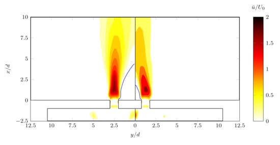
Figure 14.
Contour plot of the time-averaged streamwise velocity field , . (left), (right). A blue contour line is depicted to highlight the recirculation zones.
The distribution of the characteristic points as a function of the orifice spacing is shown in Figure 15, along with streamwise profiles of the streamwise velocity component along the x axis for different values. A linear trend for both and is obtained by the numerical simulations, in agreement with the previous studies of continuous and synthetic dual jets. It is worth noting, therefore, that although the simulations with are beyond the threshold proposed by Riazi and Ahmed [17], jet interaction still exists and it is possible to also obtain a single jet behavior for .
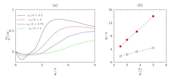
Figure 15.
(a) Streamwise distribution of the time-averaged streamwise velocity along the x axis; (b) Streamwise location of merging (∘) and combined (•) points as a function of the orifice spacing, with linear fits (dashed lines).
Finally, it is interesting to compare the streamwise position of the time-averaged merging point with the maximum extension of the phase-averaged reverse flow region , which occurs during the suction phase (as highlighted by Figure 13). As discussed in the previous section, for the case the latter is ≈2.5d, whereas ; similarly, for , and . This fact clearly highlights that, mainly due to the phase-correlated velocity contribution, negative values of the streamwise velocity may occur also downstream of the time-averaged merging point. Again, this aspect should be carefully taken into consideration to correctly design the actuator.
5. Conclusions
A combined numerical and experimental study of the performances of a piezo-driven synthetic jet in double-orifice configuration has been presented. The investigation follows the preliminary tasks of a possible design procedure of a SJ actuator in crossflow conditions. First of all, the device has been designed according to the main guidelines provided by the lumped element model technique. It is worth noting that obtaining a desired value of the jet velocity for the design frequency of the control strategy (which, in this case, is the structural one) is a crucial step for a correct assessment of the device. Indeed, several works have demonstrated that the control of shear flows is strongly dependent both on the jet-to-crossflow momentum ratio and the ratio between the actuation frequency and a characteristic flow pulsation. Such a finding is well recognized in literature for both attached [30] and separated [31] turbulent flows.
Once the baseline configuration was defined and the frequency response was obtained, numerical simulations were performed to properly investigate the main external flow topology, in terms of vortex trajectory and jet interaction as a function of the orifice spacing. Time-averaged flow fields allow to observe that, contrarily to continuous twin round jets, a strong recirculation region is formed between the orifices for relatively low orifice spacings. A close inspection of the centerline phase-averaged velocity plots reveals also that a reverse flow region is visible not only during the suction phase but also during the rest of the cycle, as it is formed by the induced velocity generated by the twin vortex rings generated by the device. This means that the time-averaged negative streamwise velocity is not only a result of the averaging process, but it actually exists for the most part of the actuation cycle, and a non-negligible probability of reverse flow can be found also beyond the time-averaged merging point. All these aspects can be crucial either in a separated flow control framework (to define an optimal orifice spacing for the crossflow under investigation) or in an impinging one; as a matter of fact, the heat transfer performances of impinging jets have found, for single-orifice actuators, to be strongly dependent on the vortex celerity and trajectory and on the existence of intense shear layers phenomena at the jet periphery [32,33].
As a conclusion, the present investigation constitutes an important step in the definition of optimized arrays of synthetic jets for separation control on aerodynamic surfaces or for heat transfer purposes. Adjacent jets can be encountered in a huge number of applications, as outlined in Section 1, and they can be generated both by multi-orifice devices and/or independent actuators. The present work confirms the existence of backflow also for higher orifice spacings () than the ones previously investigated and values of the stroke length close to the jet diameter (), which have never been treated before in this context. Moreover, the presented three-dimensional view of the interaction between vortical structures arising for low values of can be conveniently used to deduce the vortex motion in the aforementioned cases, where a crossflow or a bounding surface is concerned.
Future work in this topic should be devoted to driving quantitative comparison with dual continuous jets and single-orifice actuators. A better view of the vortex converging and merging phenomena can be obtained using modal analysis techniques, as Proper Orthogonal Decomposition and Dynamic Mode Decomposition. Experiments and numerical simulations of dual impinging synthetic jets would be also of paramount importance to provide information on the efficiency of such devices for cooling applications.
Author Contributions
The authors conceived and contributed equally to the writing of the manuscript. All authors have read and agreed to the published version of the manuscript.
Funding
This research received no external funding.
Institutional Review Board Statement
Not applicable.
Informed Consent Statement
Not applicable.
Data Availability Statement
Not applicable.
Acknowledgments
The computational part of this work was supported by a grant of HPC time from CINECA under the ISCRA-C projects NISIDA and NIDI.
Conflicts of Interest
The authors declare no conflict of interest.
Sample Availability
Experimental and numerical data are available from the authors upon reasonable request.
Abbreviations
The following abbreviations are used in this manuscript:
| CFD | Computational fluid dynamics |
| CTA | Constant temperature anemometry |
| LZT | Lead zirconate titanate |
| DNS | Direct numerical simulation |
| HWA | Hot-wire anemometry |
| PIV | Particle Image Velocimetry |
| SJ | Synthetic jet |
| Nomenclature | |
| A | Area (m) |
| a | Sound speed (m/s) |
| C | Courant number |
| D | Shim flexural rigidity (N m) |
| d | Diameter (m) |
| E | Young Modulus (Pa) |
| Hot-wire output voltage (V) | |
| f | Frequency (Hz) |
| h | Height (m) |
| K | Turbulent kinetic energy (m/s) |
| L | Stroke length (m) |
| p | Pressure (Pa) |
| Q | Volumetric flow rate (m/s) |
| Reynolds number | |
| Jet spacing (m) | |
| S | Stokes number |
| Strouhal number | |
| t | Time (s) |
| T | Actuation period (s) |
| Velocity (m/s) | |
| V | Volume (m) |
| Heat coefficient ratio | |
| Dynamic viscosity (Pa s) | |
| Poisson’s ratio | |
| Density (kg/m) | |
| Subscripts | |
| c | Cavity |
| Converging point | |
| H | Helmholtz |
| Merging point | |
| o | Orifice |
| p | Piezo-element |
| s | Shim |
| t | Total |
| w | Wall |
| 0 | Orifice area-averaged |
Appendix A. Inlet Boundary Condition
As explained in Section 2.2, the effect of the diaphragm motion is modeled by using a time-varying inlet condition for the wall-normal velocity at the lower end of the cavity. This approach has been successfully applied in several CFD works on synthetic jets as a simple way to represent the oscillating mass flow rate generated by the device [34,35] as opposed to the more computationally expensive solution of using coupled fluid-structure solvers and moving meshes. A general form of the inlet condition is given by Equation (A1)
which is enforced at the undeformed position of the wall . In this respect, several choices for the velocity spatial distribution can be made, ranging from a simple plug approximation (), used in the aforementioned works, to more complicated functions. In the present case, the orifices are placed far away from the actuator axis, which implies that the effect of the diaphragm deformation shape should not be neglected. For this reason, it has been preferred to use a velocity amplitude distribution close to the time derivative of the actual diaphragm vibration shape. The governing equation describing the vibration of a thin plate of thickness is given by Equation (A2)
where q is the external forcing, is the shim flexural rigidity (with and being the Young modulus and the Poisson’s ratio coefficient, respectively), its density and its rotatory inertia. In general, the external forcing is the superposition of two different loads: the force generated by the interaction of the shim with the deformated piezo disk and the pressure force, caused by the difference between the cavity pressure and the external one, which makes difficult to find an analytical solution to the problem. However, given that the actuation frequency for the simulated cases is equal to the structural frequency of the diaphragm, it can be reasonably assumed that the actual deformation shape is equal to the leading free, axisymmetric vibrational mode of a clamped plate. Its analytical expression is given by the solution of the eigenvalue problem arising from the introduction of the modal ansatz into Equation (A2) (with the additional approximation of neglecting the term) [36]
with . The leading eigenvalue is given by the solution of the non-linear equation
with , and and are, respectively, the n-th order Bessel function and the Bessel modified one. The numerical solution of the non-linear eigenvalue relation is , thus obtaining
The corresponding eigenmode is
and therefore
where , and . Laser-Doppler vibrometer measurements (not shown herein), carried out at the structural resonance frequency of the actuator, corroborated the present ansatz. Finally, the amplitude of the diaphragm motion is obtained by enforcing the global cycle-averaged mass conservation between the diaphragm and the orifices. The mass conservation equation reads
where is the peak velocity at the orifices exit of the SJ actuator, is the orifices number and is the mean inlet velocity amplitude, given by
The inlet condition was implemented in OpenFOAM using the codeStream utility, and the Bessel functions are evaluated using their truncated Taylor series expansions [37]:
with the first terms adequately approximating the Bessel distributions.
Appendix B. Calibration of the Hot-Wire Anemometer
The calibration has been carried out in order to define a transfer function between the hot-wire output voltage and the flow velocity. Such relation has been obtained using the procedure outlined in [38]: the hot-wire probe is exposed to different (known) velocity values, thus obtaining several points in the plane. A best-fit curve, defined by Equation (A9), is then reconstructed from the HW data and used as transfer function.
In the present calibration, the hot-wire has been located at the exit of a converging nozzle of circular cross-section; the evaluation of the jet velocity generated outside of the nozzle is obtained by comparing the hot-wire data with concurrent measurements of the pressure difference along the contoured nozzle, which is related to it using the Bernoulli equation
where is the speed of sound, defined with reference to the total temperature . A radiator was used to prevent temperature increases in the external air flow due to the compressibility effects generated by the nozzle. Several jet velocities were obtained by changing the between the total pressure (in a reservoir upstream of the nozzle) and the static external one P. This pressure difference was detected by two differential pressure transmitters (All Sensors and Honeywell pressure transducers, with a range respectively of ±0.25 and ±2 in HO and accuracy of 0.05 and 0.25%), whose output voltage is acquired by the USB Instruments DS1M12, which is also used for the applied voltage E acquisition and post-processing. The results of the calibration procedure are shown in Figure A1; the chosen velocity range reaches m/s, which safely exceeds the maximum SJ velocity, to avoid extrapolation in the subsequent experimental phases.
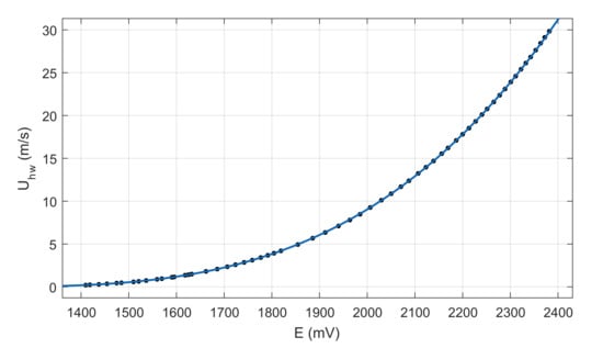
Figure A1.
Calibration curve: relation between the applied voltage and the velocity U.
References
- Rice, T.T.; Taylor, K.; Amitay, M. Pulse modulation of synthetic jet actuators for control of separation. Phys. Rev. Fluids 2021, 6, 093902. [Google Scholar] [CrossRef]
- Jansen, K.; Rasquin, M.; Farnsworth, J.; Rathay, N.; Monastero, M.; Amitay, M. Interaction of a Synthetic Jet with Separated Flow over a Vertical Tail. AIAA J. 2018, 56, 2653–2668. [Google Scholar] [CrossRef]
- Velasco, D.; Mejia, O.L.; Laín, S. Numerical simulations of active flow control with synthetic jets in a Darrieus turbine. Renew. Energy 2017, 113, 129–140. [Google Scholar] [CrossRef]
- Gil, P.; Wilk, J.; Smusz, R.; Gałek, R. Centerline heat transfer coefficient distributions of synthetic jets impingement cooling. Int. J. Heat Mass Transf. 2020, 160, 120147. [Google Scholar] [CrossRef]
- Glezer, A.; Amitay, M. Synthetic Jets. Annu. Rev. Fluid Mech. 2002, 34, 503–529. [Google Scholar] [CrossRef]
- Chiatto, M.; Hlevca, D.; Grasso, F.; de Luca, L. Modal Analysis of Actively Controlled Flow Past a Backward Facing Ramp. In Proceedings of the AIAA Scitech 2020 Forum, AIAA Paper 2020-0100, Orlando, FL, USA, 6–10 January 2020; pp. 1–13. [Google Scholar]
- Chiatto, M.; de Luca, L.; Grasso, F. Modal analysis of actively controlled flow past a backward facing ramp. Phys. Rev. Fluids 2021, 6, 064608. [Google Scholar] [CrossRef]
- Smith, B.; Glezer, A. Vectoring of adjacent synthetic jets. AIAA J. 2005, 43, 2117–2124. [Google Scholar] [CrossRef]
- Chaudhari, M.; Puranik, B.; Agrawal, A. Heat transfer characteristics of synthetic jet impingement cooling. Int. J. Heat Mass Transf. 2010, 53, 1057–1069. [Google Scholar] [CrossRef]
- Mangate, L.; Chaudhari, M. Experimental study on heat transfer characteristics of a heat sink with multiple-orifice synthetic jet. Int. J. Heat Mass Transf. 2016, 103, 1181–1190. [Google Scholar] [CrossRef]
- Luo, Z.; Xia, Z.; Liu, B. New Generation of Synthetic Jet Actuators. AIAA J. 2006, 44, 2418–2419. [Google Scholar] [CrossRef]
- He, W.; Luo, Z.B.; Deng, X.; Xia, Z.X. Experimental investigation on the performance of a novel dual synthetic jet actuator-based atomization device. Int. J. Heat Mass Transf. 2019, 142, 118406. [Google Scholar] [CrossRef]
- Alimohammadi, S.; Fanning, E.; Persoons, T.; Murray, D. Characterization of flow vectoring phenomenon in adjacent synthetic jets using CFD and PIV. Comput. Fluids 2016, 140, 232–246. [Google Scholar] [CrossRef]
- Berk, T.; Gomit, G.; Ganapathisubramani, B. Vectoring of parallel synthetic jets: A parametric study. J. Fluid Mech. 2016, 804, 467–489. [Google Scholar] [CrossRef] [Green Version]
- Watson, M.; Jaworski, A.J.; Wood, N. A study of synthetic jets from rectangular and dual-circular orifices. Aeronaut. J. 2003, 107, 427–434. [Google Scholar]
- Watson, M.; Jaworski, A.J.; Wood, N.J. Contribution to the understanding of flow interactions between multiple synthetic jets. AIAA J. 2003, 41, 747–749. [Google Scholar] [CrossRef]
- Riazi, H.; Ahmed, N. Numerical investigation on two-orifice synthetic jet actuators of varying orifice spacing and diameter. In Proceedings of the 29th AIAA Applied Aerodynamics Conference, Honolulu, HI, USA, 27–30 June 2011; pp. 2011–3171. [Google Scholar]
- Chiatto, M.; Capuano, F.; de Luca, L. Numerical and experimental characterization of a double-orifice synthetic jet actuator. Meccanica 2018, 53, 2883–2896. [Google Scholar] [CrossRef]
- Ceglia, G.; Invigorito, M.; Chiatto, M.; Greco, C.S.; Cardone, G.; de Luca, L. Flow characterization of an array of finite-span synthetic jets in quiescent ambient. Exp. Therm. Fluid Sci. 2020, 119, 110208. [Google Scholar] [CrossRef]
- Palumbo, A.; Chiatto, M.; de Luca, L. Measurements versus Numerical Simulations for Slotted Synthetic Jet Actuator. Actuators 2018, 7, 59. [Google Scholar] [CrossRef] [Green Version]
- Kim, M.; Lee, H.; Hwang, W. Experimental study on the flow interaction between two synthetic jets emanating from a dual round orifice. Exp. Therm. Fluid Sci. 2021, 126, 110400. [Google Scholar] [CrossRef]
- Chiatto, M.; Capuano, F.; Coppola, G.; de Luca, L. LEM characterization of synthetic jet actuators driven by piezoelectric element: A review. Sensors 2017, 17, 1216. [Google Scholar] [CrossRef] [Green Version]
- Chiatto, M.; Palumbo, A.; de Luca, L. Design approach to predict synthetic jet formation and resonance amplifications. Exp. Therm. Fluid Sci. 2019, 107, 79–87. [Google Scholar] [CrossRef]
- de Luca, L.; Girfoglio, M.; Coppola, G. Modeling and experimental validation of the frequency response of synthetic jet actuators. AIAA J. 2014, 52, 1733–1748. [Google Scholar] [CrossRef]
- Moffat, R. Describing the uncertainties in experimental results. Exp. Therm. Fluid Sci. 1988, 1, 3–17. [Google Scholar] [CrossRef] [Green Version]
- Hunt, J.; Wray, A.; Moin, P. Eddies, Streams, and Convergence Zones in Turbulent Flows; CTR Summer Program; Center for Turbulence Research: Stanford, CA, USA, 1988. [Google Scholar]
- Tanaka, E. The interference of two-dimensional parallel jets: 1st report, experiments on dual jet. Bull. JSME 1970, 13, 272–280. [Google Scholar] [CrossRef] [Green Version]
- Okamoto, T.; Yagita, M.; Watanabe, A.; Kawamura, K. Interaction of twin turbulent circular jet. Bull. JSME 1985, 28, 617–622. [Google Scholar] [CrossRef]
- Laban, A.; Aleyasin, S.; Tachie, M.F.; Koupriyanov, M. Experimental Investigation of Nozzle Spacing Effects on Characteristics of Round Twin Free Jets. J. Fluids Eng. 2019, 141, 071201. [Google Scholar] [CrossRef] [Green Version]
- Palumbo, A.; Semeraro, O.; Robinet, J.C.; de Luca, L. Receptivity to synthetic jet actuation in boundary layer flows. In Proceedings of the AIAA Scitech 2020 Forum, AIAA Paper 2020-0099, Orlando, FL, USA, 6–10 January 2020; pp. 1–16. [Google Scholar]
- Dandois, J.; Garnier, E.; Sagaut, P. Numerical simulation of active separation control by a synthetic jet. J. Fluid Mech. 2007, 574, 25–58. [Google Scholar] [CrossRef]
- Greco, C.S.; Paolillo, G.; Ianiro, A.; Cardone, G.; de Luca, L. Effects of the stroke length and nozzle-to-plate distance on synthetic jet impingement heat transfer. Int. J. Heat Mass Transf. 2018, 117, 1019–1031. [Google Scholar] [CrossRef]
- Arshad, A.; Jabbal, M.; Yan, Y. Synthetic jet actuators for heat transfer enhancement—A critical review. Int. J. Heat Mass Transf. 2020, 146, 118815. [Google Scholar] [CrossRef]
- Kotapati, R.; Mittal, R.; Cattafesta III, L. Numerical study of a transitional synthetic jet in quiescent external flow. J. Fluid Mech. 2007, 581, 287–321. [Google Scholar] [CrossRef] [Green Version]
- Capuano, F.; Palumbo, A.; de Luca, L. Comparative study of spectral-element and finite-volume solvers for direct numerical simulation of synthetic jets. Comput. Fluids 2019, 179, 228–237. [Google Scholar] [CrossRef]
- Reddy, J.N. Theory and Analysis of Elastic Plates and Shells; CRC Press: Boca Raton, FL, USA, 2006. [Google Scholar]
- Abramowitz, M.; Stegun, I.A. Handbook of Mathematical Functions with Formulas, Graphs, and Mathematical Tables; US Government Printing Office: Washington, DC, USA, 1964. [Google Scholar]
- Jørgensen, F.E. How to Measure Turbulence with Hot-Wire Anemometers: A Practical Guide; Technical Report; Dantec Dynamics: Skovlunde, Denmark, 2002. [Google Scholar]
Publisher’s Note: MDPI stays neutral with regard to jurisdictional claims in published maps and institutional affiliations. |
© 2021 by the authors. Licensee MDPI, Basel, Switzerland. This article is an open access article distributed under the terms and conditions of the Creative Commons Attribution (CC BY) license (https://creativecommons.org/licenses/by/4.0/).