1. Introduction
The giant magnetostrictive actuator (GMA), also known as the linear magnetostrictive motor (LMM), is the object of continuous innovation and intense research. The working principle and design of the LMM rely on the deformation of a magnetostrictive (MS) rod that is part of the magnetic circuit of the actuator. The MS rod contracts when the magnetic flux goes through and elongates to the rest state (size) when the magnetic field is suppressed. The size of the magnetostrictive rod deformation is proportional to the magnetic field provided by the coil system that, in turn, is a function of the electrical current. Liu et al. proposed a magnetostrictive actuator in which the bias magnetic field is provided by alternatively stacking permanent magnets with giant magnetostrictive material (GMM) rods to produce a stacked magnetic-biased giant magnetostrictive actuator (SGMA) [
1]. Dorota et al. proposed a simplified form of a GMA that consists of a cylindrical Terfenol-D (Tb–Dy–Fe alloy) rod, which is magnetically excited by a coil surrounding the rod to generate strain and force.
Moreover, axial compression (mechanical bias) may be used to enhance the magnetostrictive strain of the Terfenol-D rod; hence, the GMM is usually pre-stressed with a spring. Of these two (magnetization and pre-stress), the proposed model in [
2] accounts for the mechanical bias only. GMAs are generally used in applications where several requirements must be met simultaneously, such as high forces (hundreds of N), small linear displacements (tens of μm), and high frequencies (of up to 15 kHz). In this regard, an ultrasonic transducer based on rare-earth giant magnetostrictive materials could be designed to comply with the technical requirements of ultrasonic surface strengthening [
3].
GMAs are used for a range of applications that other available devices, e.g., piezo-actuators, may not provide. Microactuation permitting high strokes of high energy density and acceptable frequency bands enabled the spread of Terfenol-D-based actuators until the 1990s. Then, the new Fe-Ga binary alloy capable of lower strokes but much higher mechanical performances boosted innovative device design.
Apicella et al. revealed that the development of new types of active GMMs, with better mechanical properties; higher magnetostriction coefficient, energy density, and magnetic conversion efficiency; and faster response, such as Terfenol-D, Galfenol, and, in perspective, other iron alloys such as FeCo and FeAl, may lead to broad applications in several potential fields. These applications cover a wide range of micropositioning, motors, active vibration control, micro-pumping, and automotive areas like needle actuation for fuel injectors and aerospace applications [
4]. For instance, [
5] reported on an ultrasonic GMA using a compound of rare earth elements, including Terfenol-D, which was fabricated and tested. In [
6], an efficient damage-detection system for structural health monitoring in composites, with potential applications in the aerospace industry to detect and monitor cracks in critical aerospace components, is presented. Huang et al. proposed a model of a GMA for which the principal parts consist of a cylindrical Terfenol-D rod, an activation coil, an enclosing permanent magnet, a pre-stressed bolt, and a spring washer. A numerical dynamic model for giant magnetostrictive actuators is presented based on the Hamilton principle of minimum potential energy. The finite element method (FEM) was used to calculate the relation between the exciting magnetic field and the output displacement of the actuator [
7,
8].
GMA distinguishes itself by robust construction and the possibility of reaching forces up to hundreds of N. The excellent dynamic properties and the ability to work at higher frequencies up to 15 kHz qualifies it to be used to control fuel injectors [
9,
10]. An essential role in the functioning of the GMA injection is played by the external mechanical stress (pre-stress) and by the bias magnetic field [
10]. The bias magnetic field was provided by a permanent magnet positioned at the bottom of the active GMM core. The mathematical model describing the GMA’s physics under variable load was FEM-solved [
10,
11,
12].
Using an optimal design method, Dehui et al. [
13] proposed, designed, and tested a GMA prototype with improved performance: a displacement in the range of 70 μm, a precision of 0.05 μm, and a driving force of 500 N. Terfenol-D, one of the most used GMMs, has a low relative permeability of about four, which is responsible for leakage flux. In this regard, to ensure a homogeneous magnetic field along the rod, the flux leakage at the rod ends has to be compensated for [
14]. GMA is also used in hydraulic servo-valve systems where the output displacement of the actuator may be detected by measuring the change in the activation coil voltage [
15].
The bias magnetic field can be produced by using a cylindrical, axially magnetized permanent magnet [
7,
8], by several permanent magnets stacked with the active magnetostrictive material [
1], or by a permanent magnet positioned near the MAC, at the bottom [
3,
10]. However, for enhanced and flexible control of GMA (the LMM), the bias magnetic field can be produced by either a magnetic bias coil [
16,
17] or a combination of permanent magnets and a magnetic bias coil [
18]. The magnetic bias coil can either be powered by a DC source [
16,
17] or by a pulse width modulation (PWM) modulator, which provides a rectangular pulse train of a set frequency [
18,
19]. The duty cycle may be adjusted to minimize Joule losses.
The shape and structure (constructal) optimization of the GMA core concerning its geometric ratio (height/width) was evidenced to be a critical stage of design [
18,
20]. Constructal optimization aims at GMA core morphology, which enables the GMM to reach a working state that complies, as optimally as possible, with internal fluxes (magnetic and mechanical) and external constraints (mechanical load). This optimization allows the LMM performance to be maximized in terms of linear motion dynamics.
This body of work—the concept, design, fabrication, and validation of an LMM for outer space applications—is the object of this paper. In the following, we present the notional LMM model that bears the main constructive and functional features, the numerical simulation-assisted design and validation of the LMM prototype, and the numerical and physical experiments that were performed to validate the LMM prototype, which provides a maximum force of 225.177 N and a maximum mechanical excursion A100 = 30 μm for 28 VDC at f = 100 Hz.
2. Materials and Methods
2.1. The Linear Magnetostrictive Motor
The active material of the magnetostrictive core 1 (
Figure 1) achieves a longitudinal deformation taken by the pusher rod (2) under the action of the magnetic field of the activation coil (10). On the GMM core, the permanent (1) acts a bias magnetic field, which is obtained by the cumulative effect of the magnetic field of the permanent magnets of cylindrical shape ((3) and (4)) respectively of the magnetic field generated by the coil of magnetic bias (12). The activation coil (10) is wound on the housing (9) and is excited with the voltage U1 using PWM1, utilizing an electronic block arranged in the area for the integration of the electric drive system (23). The magnetic bias coil (12) is wound on the housing (11) and is excited with voltage U2 with PWM2, utilizing an electronic block also arranged in the area (23). The characteristics of the PWM1 and PWM2 waveforms, frequency, and duty cycles are given by the specific application.
The mechanical pre-stress (bias) causes rotation of the magnetic moments for the active GMM core so that they are aligned perpendicular to the applied tensioning force. Consequently, a variation ΔB of the magnetic field induction produces a larger variation, Δl, of the GMM core (1), so that Δl >> Δl1, where Δl1 is the variation of the length of the active GMM core in the absence of mechanical bias. The mechanical bias is produced by the pre-tensioning spring (5), with five turns and an elastic constant of 5000 N/m. The ring (6), made of a material with low magnetic remanence, grips the active GMM core (1) so that the lower magnet (4) is in its immediate vicinity. The ring (6) is split (a gap of 0.8 mm) to not short-circuit the coil, as is the rod (13), which aims to fix the components of (A). The plate (7) is fastened to the pusher rod (2) using the fixing screw (8).
The components of (A) and (B) (see
Appendix A are arranged in the inner half-housing (14). The brass sleeve (15) is aimed at reducing the coefficient of friction between the pusher rod (2) and the inner half-housing (14). It is fixed to the intermediate cover (16) on the upper face by gluing the lower magnet (4). All three subassemblies ((A), (B), and (C)) (see
Appendix A) are inserted into the outer half-housing (20) and are fixed with the lower cover (21) by four screws. The inner half-housing (14) is fixed to the external half-housing (20) through the fixing screw (22).
Figure 1b shows the LMM.
2.2. Constructive and Functional Special Features
The LMM is designed to operate in outer space, in a vacuum, in the absence of the Earth’s gravitational field. Consequently, the heat produced by the active central subassembly (A) and the coil subassembly (B) (see
Appendix A) cannot be released to the environment by convection, and only thermal radiation can be utilized. The total current absorbed is drastically limited to a maximum of 2 A for the entire LMM. The DC supply voltage has to be in the range of U = 18 V–28 V, which is the voltage that is provided by photovoltaic panels used in outer space. Peltier elements (17) are used [
19] to subcool the active central subassembly (A) and the coil subassembly (B) (see
Appendix A) to lower than the contextual working temperature.
Peltier elements are supplied at U3 voltage, employing an electronic modulator block, PWM3, also placed in the area for the integration of the electric drive system (23). U3 has a peak-to-peak amplitude of 18–28 V and a duty cycle 30% at f = 24 kHz to minimize the current drained by Peltier elements.
Both the activation coil and the magnetic bias coil are supplied with PWM voltages U1 and U2 of the same peak-to-peak amplitude and frequency to minimize Joule losses. However, the duty cycle for U1 is k = 70%, and the duty cycle for U2 is k = 40%. For the same reason, a constructive feature of the magnetic bias coil is that the DC resistance is RDC = 81 Ω.
2.3. The Design and Validation of the LMM Prototype
Mathematical modeling and numerical simulation are part of the design cycle, from GMM core optimization, LMM sizing, fabrication, and experimental validation, at all stages. In what follows, we present the electromagnetic field and structural design modeling approach, which has shown to be rewarding in terms of design duration and product quality.
2.3.1. The Mathematical Model
The mathematical model for the linear magnetostrictive motor accounts for the magnetic field and the structural mechanics that concur with its operation.
Figure 2 shows the computational domain that relies on the assumed symmetry of the motor (structural and functional), which allowed the problem to be reduced to a 2D axial model.
This hypothesis reduced the numerical complexity and the associated computational effort significantly. The associated quasi-stationary magnetic field problem is described by [
19]:
for the GMM core, and
for all the other parts. Here,
[T⋅m] is the magnetic vector potential,
[A/m
2] is the electric current density (the azimuthal component),
is the azimuthally unit vector, and
H [A/m] is the magnetic field strength. The boundary conditions were “symmetry,” on the symmetry axis, and magnetic insulation (
n ×
A = 0, where
n is the outward pointing normal to the boundary). Homogeneous initial conditions were assumed. The GMM core was made of Terfenol-D (T-D). The H–B curves of the first magnetization are shown in
Figure 3 for the two analyzed cases: no-load operation and on-load operation, respectively 0 ksi and 3 ksi (i.e., 210.921 kgf/cm
2, or ~20.6843 MPa).
The GMM core was prestressed for maximum magnetostrictive effect using a spring, which was assumed to be linear. Its elasticity constant was K = 5153 N/m. The generalized Hooke law [
19]
was used to model the axial deformation of the T-D core. Here, [C] [N/m] is the rigidity matrix, [ε] [m] is the elongation, [ε
i] [m] is the initial elongation, [σ] [N] is the tension, and [σ
i] [N] is the pre-stress state. The non-linear coupling between the magnetic field and the structural response of the GMM core is given by
where λ
r,z are the magnetostriction coefficients, which depend on the magnetostriction constant λ
S and the direction of the magnetization, in this case, the
Oz direction. The aluminum frame was assumed to be rigid, with no displacement, whereas the core, the steel rod, and the magnets were free to deform, assuming axial symmetry was preserved. A roller-type, frictionless condition was used for the interface between the rod and the casing. The system was mechanically prestressed by the spring. The mathematical models (1)–(4) were solved using the finite element method (FEM).
The two-way magnetoelastic coupling (the magnetic state of the system depends on its mechanical state and reciprocally) requires the solution of the magnetic and structural field at the same time, and to reduce the computational effort, a segregated time-stepping approach was used. The mathematical model was solved numerically using FEM [
19]. The FEM mesh is shown in
Figure 4. Areas that were not occupied by material bodies did not occur in the structural analysis.
2.3.2. Numerical Sizing and Experiments
Figure 5 shows the magnetic field and the deformations when both windings were fed (PWM currents). It can be observed that the inner ferromagnetic casing conveyed the magnetic field. The maximum value of the magnetic flux density did not exceed 2.1 T, ensuring the operation of the ferromagnetic core below the saturation limit.
The drive rod was compressed under the action of mechanical load 3.44738 MPa (0.5 ksi) and the GMM core expanded under the action of the magnetic field. Its maximum relative deformation was approx. 7.6 μm. Numerical simulations were then performed for PWM frequencies of 20, 100, and 15,000 Hz for the duty cycles of
kbias = 0.4 and
kex = 0.7, corresponding to the voltages applied to the bias and excitation coils, respectively. We consider the measurement points for deformation as shown in
Figure 6.
Figure 7 shows the deformations of the tip of the drive rod (in red) and the upper end of the GMM part, (in blue). For on-load operation, the drive rod was pressed by a weight that provided 3.44738 MPa (0.5
ksi), i.e., 351.535 kgf/cm
2.
Other numerical simulations were conducted for 3D models that may have accounted for the PWM voltage excitation [
21,
22]. It was observed that the electric and structural eigenfrequencies of the LMM and power spectrum of the applied voltage (PWM excitation) were independent factors that contributed to the electromechanical work and could be adjusted to reach an optimal LMM mechanical operation. It was evidenced that it is essential to establish the right level of prestress (
Fps): To increase
Fps, the phase lag between the displacement of the drive rod and the coil voltage excitation decreases. Moreover, when increasing
Fps, if the mechanical eigenfrequency
fm coincides with the fundamental electrical frequency
fe, and then the harmonic components in the displacement of the drive rod tend to diminish. The functioning of the LMM at
fPWM close to
fm and, should it be the case, also near the fundamental frequency value
fe (calculated using the FFT from the axial displacement), indicates that the output connector (pushing rod) excursion turns unregular and departs from cyclic.
The spectrum of the PWM frequency fPWM, and that of the LMM structure (for a specific framing and prestress Fps) are independent quantities changeable in the optimization process of the LMM design. Essentially, the adjustment of fPWM should observe the structural eigenfrequencies of the LMM when intending to boost the displacement yield of the drive rod and a more stable operating mode. Therefore, their acquaintance is an initial step in the LMM optimal design and, later on, tuning.
2.3.3. Experimental Results and Validation
The Forces Provided by LMM
The magnetostrictive linear motor was tested in the Testing Laboratory of the Institute for Theoretical and Experimental Analysis of Aeronautical–Astronautics Structures, Romania. From the point of view of this test, the linear magnetostrictive motor is a metal cylinder with a diameter of 80 mm and a height of 231.5 mm, inside which are mounted several subassemblies and components, both mechanical and electronic. At one end of the cylinder, there is a pushing metal rod ((2) in
Figure 1) with an attached plate ((7) in
Figure 1) 80 mm in diameter and 2 mm thick.
The metallic pushing rod is the actuating element of the LMM. To fix the LMM between the plates of the INSTRON test machine with columns and electromechanical drive (
Figure 8), a preloaded elastic element was used: The motor was placed on the bottom plate, and the elastic element was placed between the actuator plate and the top plate of the testing machine. The preload force used was in the range of 8 to 10 N for all the test cases performed. The test method consisted of measuring the force developed by LMM when it was fed from a variable DC voltage source, type AGILENT U 8031A, with direct current voltages in the range of 18 to 32 V
DC.
Six test cases depending on the supply voltage of the LMM were considered.
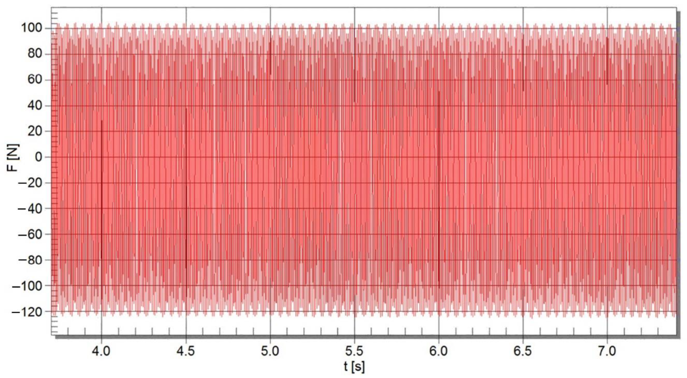
Figure 9,
Figure 10 and
Figure 11 show three of the test cases performed, namely, the cases when the LMM was supplied with 18 V
DC, 22 V
DC, and 28 V
DC, respectively. The measurement of the force developed by the LMM was done by using a 50 daN cell force and a Spider 8 signal conditioning and amplification system (
Figure 9).
The acquisition and processing of signals were made using the specific Catman 5.0 software running on a personal computer (PC). The sampling frequency of the acquired signal was 800 Hz for all test cases. The characteristics of the equipment used for measurements and their identification elements are presented in
Table 1.
The forces presented in
Figure 10 and
Figure 11 showed off envelopes of lower frequencies. We inferred that this happens because the LMM, as an electromechanical device, has electric (driven by the PVM power source), electromagnetic (mainly inductive), and mechanical eigenfrequencies and modes. A glimpse in the analysis of this complex behavior is given in [
22].
Following the test, the processing of the acquired data resulted in the values of the force developed by LMM summarized in
Table 2.
The frequency of the excitation force determined by the power spectrum analysis of the acquired signal method is shown in
Table 3. The frequency was identical to the frequency of the mechanical oscillation of the MAC.
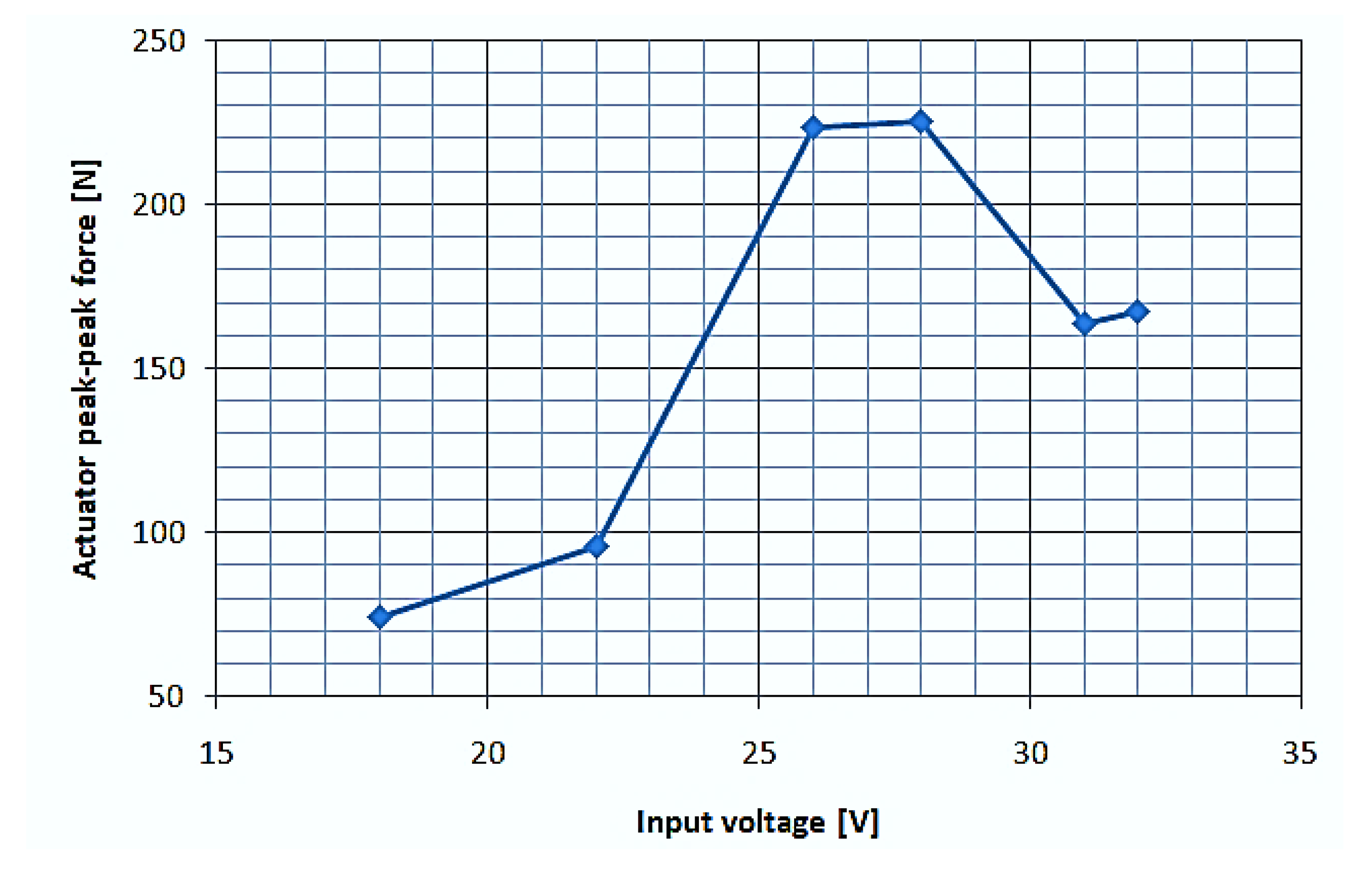
The variation of the maximum force developed by LMM for different supply voltages is seen in
Figure 12.
The maximum peak-to-peak force developed by LMM was 225.177 N and it was obtained in test case four, in which the supply voltage was 28 VDC.
The Acceleration of the Magnetostrictive Active Core LMM
Figure 16 shows the fast Fourier transform (FFT) of the magnetostrictive core acceleration for a voltage U1 applied to the activation coil PWM1 (pulse width modulation 1) with a frequency of f = 1 kHz, a peak-to-peak amplitude of U1 = 28 V, and a duty cycle of k = 70%, as well as a continuous voltage U2 = 28 V
DC applied to the magnetic bias coil. The two harmonics that accompanied the fundamental had frequencies of f
A1 = 1.4 kHz and f
A2 = 2 kHz. The amplitude of these harmonics were 0.27 ms
−2 and 0.15 ms
−2, respectively, much smaller than the fundamental of 1.082 ms
−2.
The measurements were performed using a Panasonic mechanical vibration measurement system, with accelerometer type PCB353B03, with Soundbook processing and analysis software.
The Total Current at the LMM Terminals for Different Working Conditions
Because LMM is intended for electrical drives specific to the field of space technology, the applied voltage at the coil of magnetic bias, as well as at the coil of activation, were of the PWM type with peak-to-peak amplitude correlated with the nominal voltage provided by photovoltaic panels, specifically UN = 28 VDC. The minimization of the total absorbed current for different operating regimes of LMM is a mandatory requirement. Measurements of the total absorbed current were performed at the supply terminals of LMM, with effective values for different operating regimes in the most unfavorable case in which a DC voltage U2 of 28 VDC was applied for the coil of magnetic bias, and for the coil of activation, the voltage U1 of the PWM1 type was applied. In all cases of testing, three Peltier cooling that is disposed of in series was electrically fed by a PWM module that provided a voltage UP of fixed frequency of f = 24 kHz, a peak-to-peak amplitude of A = 28 Vp-p, and a duty cycle of k = 30%.
The following experimental results were obtained:
- A.
For the voltage U1 of type PWM1 where f = 10 Hz–21 kHz, A = 28 Vp-p, and k = 50% applied to the activation coil and the DC voltage U2 = 28 V
DC applied to the magnetic bias coil, the experimental results obtained are represented in
Figure 17.
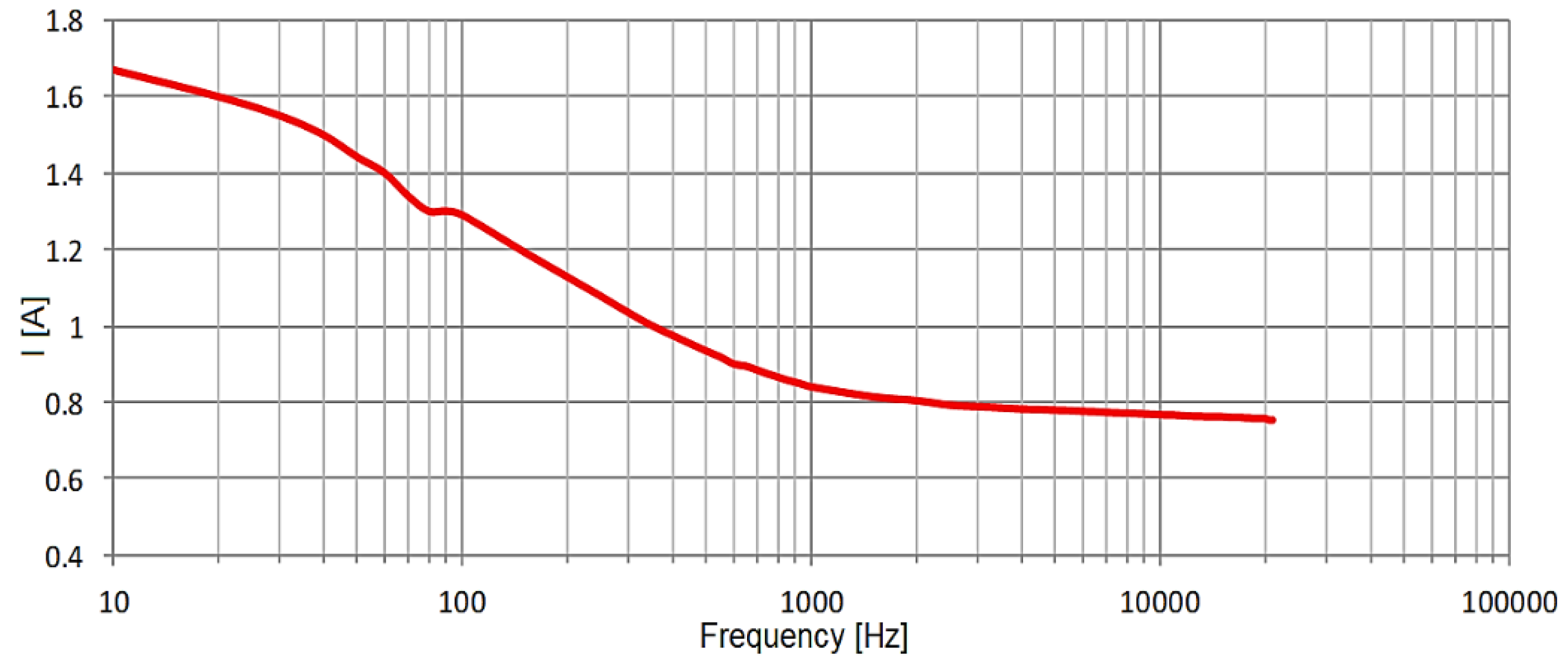
- B.
For the voltage U1 of type PWM1 where f = 10 Hz–21 kHz, A = 28 Vp-p, and k = 70% applied to the activation coil and the continuous voltage U2 = 28 V
DC applied to the magnetic bias coil, the experimental results obtained are represented in
Figure 18.
The total current absorbed by the LMM, the average value (RMS), was less than I = 1.9 A for all frequencies.
The Measurements of Total Current of the Magnetostrictive Actuator in Harsh Environments
These measurements were performed in a Vötsch climate chamber type VC 4018 (
Figure 19) to ensure the operation of the magnetostrictive actuator in harsh environments. The characteristics of the climate chamber were the following: volume 190 L, which allowed for measurements at temperatures in the range of [−40 °C, +180 °C] and humidity in the range of 10–98 RH. The following temperature values were chosen for the experiments: –30 °C, –10 °C, +10 °C, +30 °C, +50 °C, +70 °C, +90 °C, and +120 °C. The temperature value can be set and displayed by the climate chamber monitor. All measurements were performed after the temperature reached each set temperature level and at the end of a 10-min interval. An order of magnitude analysis was used to estimate the time needed for the LMM to reach the climate chamber temperature before performing each of the experiments.
For the chosen temperatures, –30 °C, –10 °C, +10 °C, +30 °C, +50 °C, +70 °C, +90 °C, and +120 °C, the total current of the magnetostrictive actuator (pos. 1,
Figure 19), was monitored in average value (RMS) for the f = 1000 Hz operating mode (
Figure 20) with the digital multimeter Agilent 34461A, 6 1/2 Digit. The voltage U1 of the PWM1 type presented the characteristics of f = 1 kHz, A = 28 Vp-p, and k = 50% applied to the activation coil and DC voltage U2 = 28 V
DC applied to the magnetic bias coil.
We may conjecture that the almost linear decrease in the electric current was mainly due to the work done by the Peltier cooling stage, whose thermal “pumping” needs to decrease as the LMM eventually reaches the thermal steady state that matches the chamber thermal conditions. The rather different behavior (higher absorbed current) at lower temperatures (–30 °C …–10 °C) may have been due, on the one hand, to the initial thermal load of the LMM that did not reach the set chamber temperature fully before starting the tests, and, on the other hand, to the Peltier cooler itself, designed for higher lowest hot head temperatures.
In addition, the temperature values of the chosen temperatures, –30 °C, –10 °C, +10 °C, +30 °C, +50 °C, +70 °C, +90 °C, and +120 °C, were monitored using a T-type thermocouple system (
Figure 21) positioned very close to the slipring bearing area of the magnetostrictive actuator (pos. 2,
Figure 19).
The temperature measurements suggest that, for the duration of the experiments, the slipring bearing worked at the climate chamber temperature, and it did not overheat. The fluctuations in the temperature measurement can be explained by its local, “pointwise” nature, unlike the current measurement, which was “global.”
3. Discussion
This paper presents the concept, design, mathematical modeling, numerical simulation, fabrication, and testing of an LMM designed to work in outer space. Several significant constraints require unique constructive solutions.
First, the cylindrical permanent magnet, axially magnetized, used in the classical construction to produce the magnetic bias field, is replaced by a magnetic bias coil and two small permanent magnets that are coaxial and have the same diameter as the magnetostrictive active core (MAC). This redundant design solves the problems that may occur if the magnets get demagnetized. An assembly of three Peltier elements subcools both the two permanent magnets, the MAC and subassemblies (A) and (B). The exhausted heat is conducted to the outer casing to be dissipated by radiation. Thus, a concern that may become a menace in LMM applications targeting outer space, namely, the demagnetization of the permanent magnet with cylindrical geometry when the temperature reaches +80 °C to +150 °C, is solved.
To solve the request for the severe limitation of the total current to max. 2A (the whole LMM) and the constraint posed by the DC supply voltage (18 VDC–28 VDC) produced by the photovoltaic panels used in outer space, the two coils (the activation and bias) and the assembly of three Peltier elements are supplied with PWM voltages, which are provided by three separate PWM modulators.
The activation and the magnetic bias coils are supplied with U1 and U2 voltages of PWM type with the same peak-to-peak amplitude and frequency to minimize Joule losses (a significant heat source). However, the duty cycle of U1 is k = 70%, whereas that for U2 is k = 40%. For the same reason, a constructive feature of the magnetic bias coil is that the DC resistance is RDC = 81 Ω. Thus, the energy dissipated by the Joule effect in the power components of PWM modulators is reduced.
Mathematical modeling and numerical simulation play a crucial role in understanding the underlying physics and working conditions of the LMM. The shape and structure (constructal) optimization of the LMM (core) may prompt solutions in morphing the system to reach a state that complies, as optimally as possible, with internal (magnetic and mechanical) and external (mechanical load) constraints. The optimal design provides for minimum resistance (reluctance) to the internal “flows” within the LMM core—the fascicular magnetic flux density and the mechanical stress, commonly known as the slenderness ratio (height/radius), which leads to the largest elongation (axial deformation) possible for the smallest amount of GMM.
The numerical simulations were aimed at identifying optimal shapes for the magnetostrictive core (MSC). Both no-load and load working conditions (20.6843 MPa, or 3 ksi) were considered for several GMM core volumes with different initial slenderness (aspect) ratios in pre-magnetized and pre-stressed, unexcited states. The main finding was the existence of maximal elongations for load and, within a limited range of GMM core volume, for no-load working conditions.
The usage of 3D models alleviates the difficulties related to using the electrical current (in 2D models) compared to the voltage excitation (for 3D models), which is consistent with the actual working conditions of the LMM.
The numerical simulation provided clues on the right level of pre-stress. For instance, when the stresses increase, the phase delay between the displacement of the drive rod and the excitation voltage decreases. When the dominant PWM frequency approaches the mechanical, structural frequency of the harmonic components of the drive rod displacement vanishes out; yet another finding, though expected, is the need for an adequate adjustment of the pre-stress level such that the drive rod reaches the rest state. The mechanical eigenmodes and frequencies and the spectral analysis of the drive rod displacement may be used to tune the LMM to avoid less-stable working conditions.
The LMM here showed off the subsequent performances during the tests: a maximum force of 225.177 N for the supply voltage 28 VDC, and a peak-to-peak amplitude of the mechanical oscillation of the MAC A100 = 30 μm at f = 100 Hz. As expected through design, the total current of the LMM does not exceed an I = 1.9 A effective value. Subsequent research aims to minimize the total current absorbed at the LMM terminals while maximizing the amplitude of the mechanical oscillation for the entire frequency spectrum of f = 0.5 Hz–15,000 Hz.
A set of experiments was conducted using a thermal metrological-level chamber that provides for controlled temperature conditions in the range of –30 °C… +120 °C to assess the robustness of the LMM under harsh thermal working conditions. The almost linear decrease in the electric current that was observed was mainly the result of the work done by the Peltier cooling stage, whose thermal “pumping” needs to decrease and eventually reaches the thermal steady state that matches the chamber thermal conditions. The temperature measurements indicate that for the duration of the experiments, the slipring bearing does not overheat. It works at the climate chamber temperature.
The LMM described in this paper is representative of a family of products for applications that cover a wide range of frequencies in the range of f = 0.5 Hz–15,000 Hz, specially designed for space industry applications. It can be used to equip devices that modulate fuel injection for rocket engines and/or machines used to correct positioning in circumterrestrial orbit.


 ,
, 


