
Design of an Anti-Slip Mechanism for Wheels of Step Climbing Robots


Abstract
:1. Introduction
2. Working Principle and Design Approach
2.1. Working Principle
2.2. Design Approach
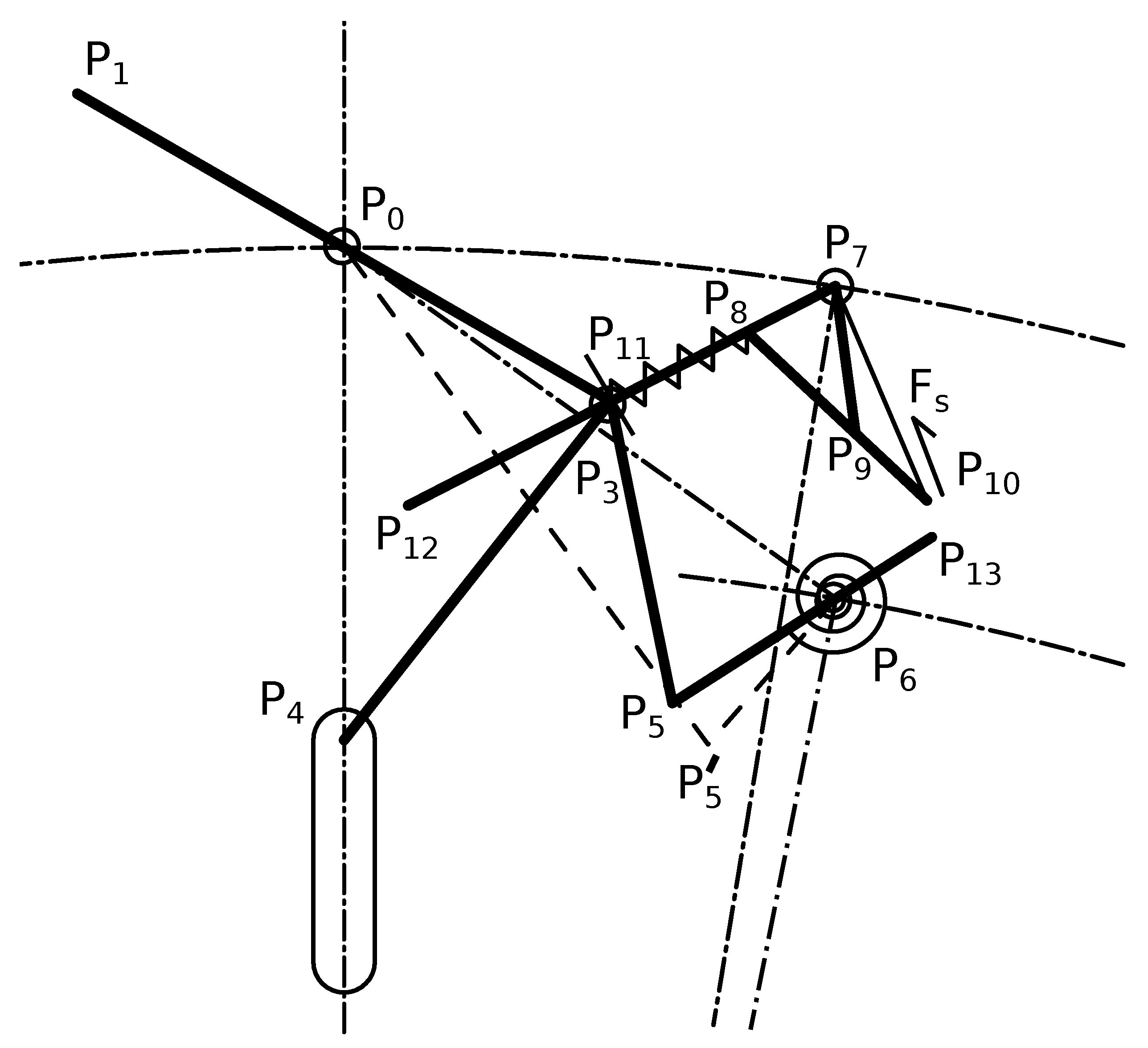
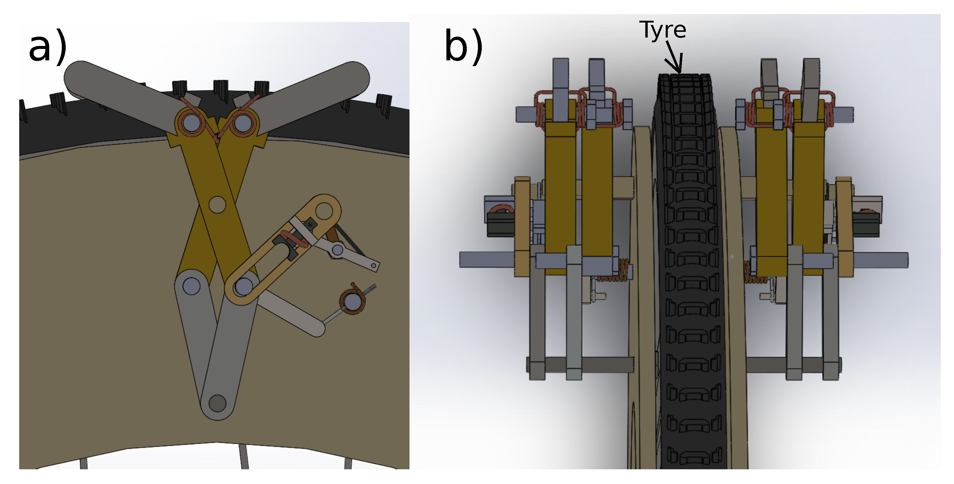
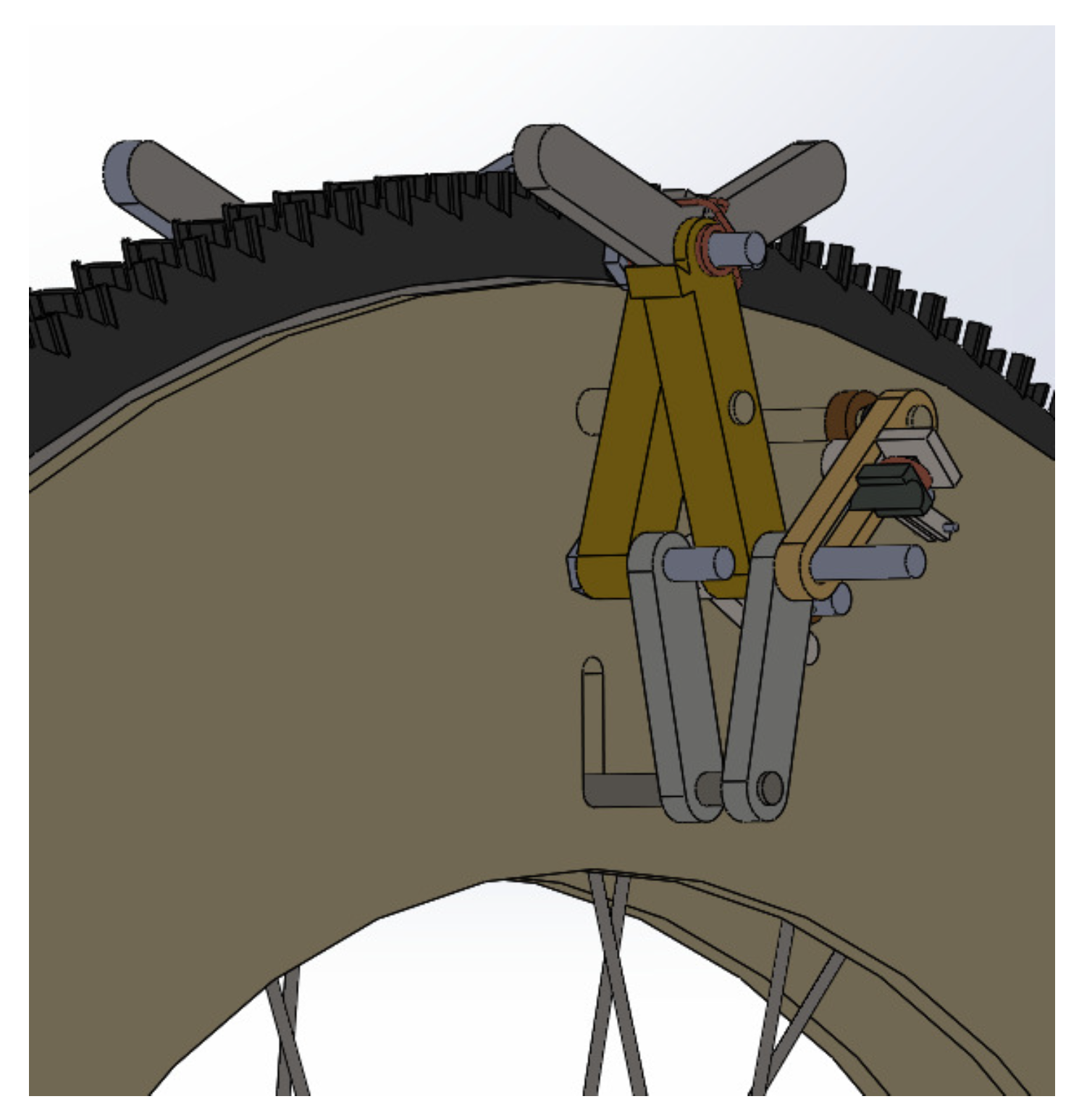
3. Design and Modeling
3.1. Chain 1: Clamping Mechanism
3.2. Chain 2: Bi-Stable Four Bar Mechanism
3.3. Chain 3: Actuator Mechanism
3.4. Force Requirement of the SMA Actuator
3.5. Actuation Length of an SMA Actuator
4. Results and Discussion
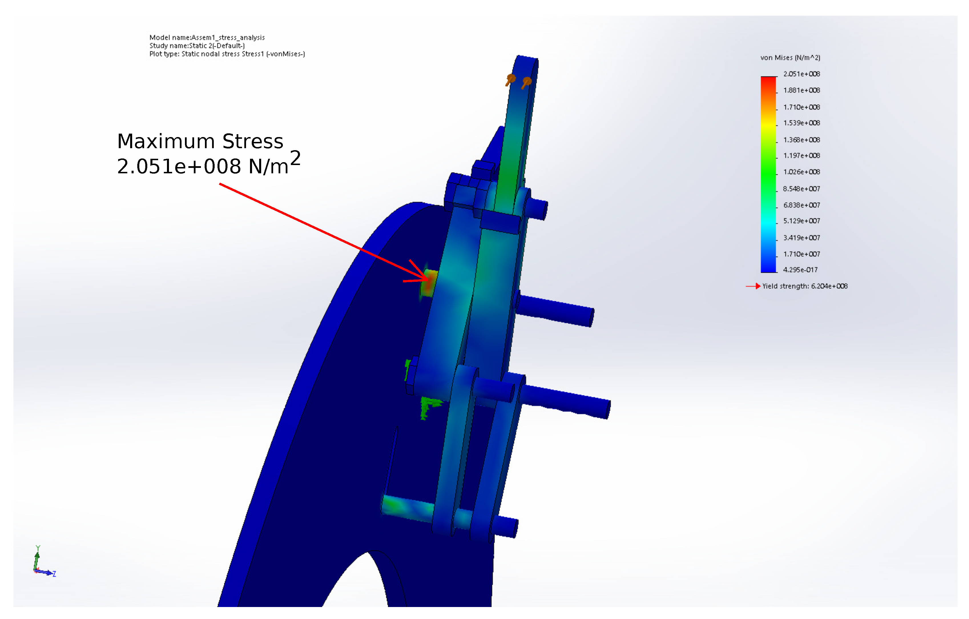
4.1. Stress Analysis
4.2. Motion Analysis
5. Conclusions
Author Contributions
Funding
Conflicts of Interest
Abbreviations
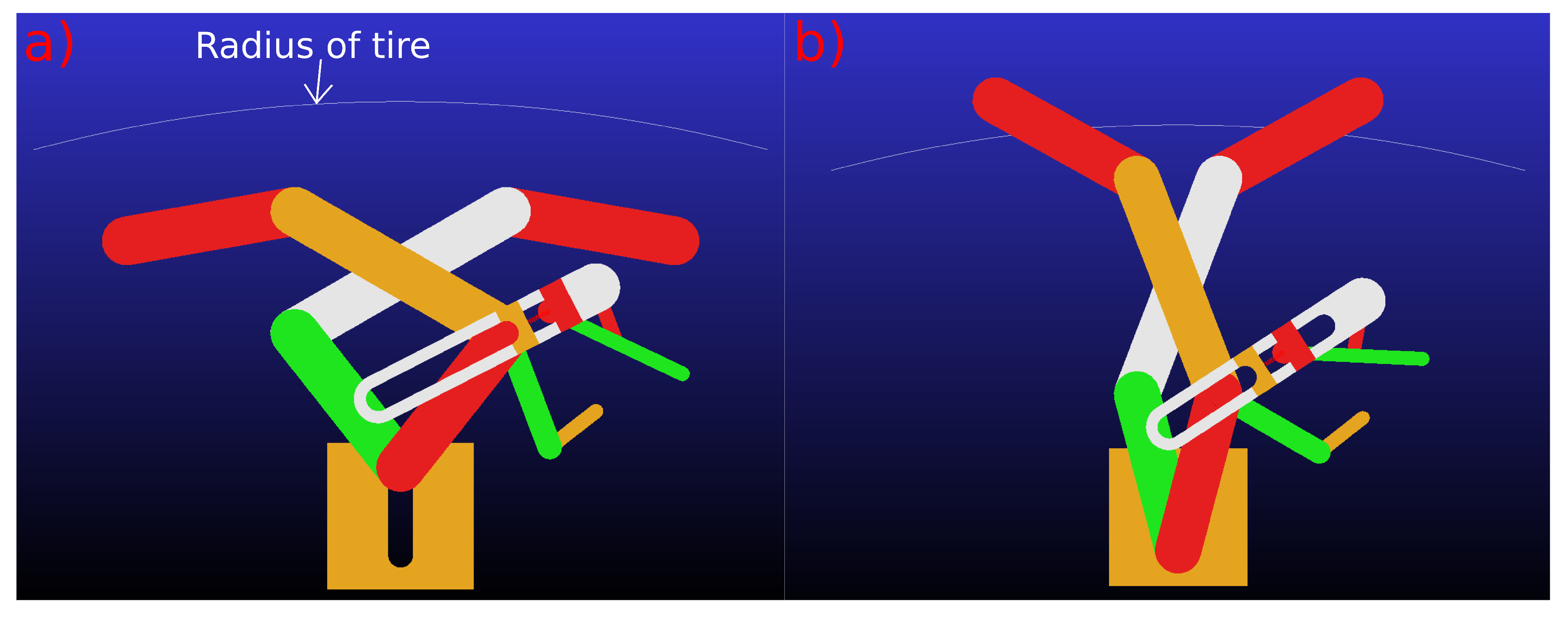
| Radius of tire | |
| Outer radius of base plate | |
| Inner radius of base plate | |
| Radius of point (x is variables) | |
| Length of slot 1 | |
| Angle of point with vertical | |
| Angle of point with vertical | |
| Angle between link 1 and link 2 | |
| Acute angle between points A, B, and C with B as vertex (A,B,C are variables) | |
| distance between points i and j | |
| Angle made by link i with horizontal (in a counterclockwise direction) |
References
- Lawn, M.J.; Sakai, T.; Kuroiwa, M.; Ishimatsu, T. Development and practical application of a stairclimbing wheelchair in Nagasaki. Int. Hum. Friendly Welf. Robot. Syst. 2001, 2, 33–39. [Google Scholar]
- Hirose, S.; Fukushima, E.F.; Damoto, R.; Nakamoto, H. Design of terrain adaptive versatile crawler vehicle HELIOS-VI. In Proceedings of the 2001 IEEE/RSJ International Conference on Intelligent Robots and Systems, Maui, HI, USA, 29 October—3 November 2001; Volume 3, pp. 1540–1545. [Google Scholar] [CrossRef]
- Yu, S.; Wang, T.; Li, X.; Yao, C.; Wang, Z.; Zhi, D. Configuration and tip-over stability analysis for stair-climbing of a new-style wheelchair robot. In Proceedings of the 2010 IEEE International Conference on Mechatronics and Automation, ICMA 2010, Xi’an, China, 4–7 August 2010; pp. 1387–1392. [Google Scholar] [CrossRef] [Green Version]
- Sugahara, Y.; Ohta, A.; Hashimoto, K.; Sunazuka, H.; Kawase, M.; Tanaka, C.; Lim, H.O.; Takanishi, A. Walking up and down stairs carrying a human by a biped locomotor with parallel mechanism. In Proceedings of the 2005 IEEE/RSJ International Conference on Intelligent Robots and Systems, Edmonton, AB, Canada, 2–6 August 2005; pp. 1489–1494. [Google Scholar]
- Yuan, J.; Hirose, S. Research on leg-wheel hybrid stair-climbing robot, Zero Carrier. In Proceedings of the 2004 IEEE International Conference on Robotics and Biomimetics, Shenyang, China, 22–26 August 2004; pp. 654–659. [Google Scholar] [CrossRef]
- Bang, Y.B.; Lee, C.H.; Yoo, J.H.; Lee, K.M.; Kim, I.S. Two-legged stair-climbing wheelchair and its stair dimension measurement using distance sensors. In Proceedings of the 2011 11th International Conference on Control, Automation and Systems, Gyeonggi-do, Korea, 26–29 October 2011; pp. 1788–1791. [Google Scholar]
- Wang, H.; He, L.; Li, Q.; Zhang, W.; Zhang, D.; Xu, P. Research on a kind of leg-wheel stair-climbing wheelchair. In Proceedings of the 2014 IEEE International Conference on Mechatronics and Automation, Tianjin, China, 3–6 August 2014; pp. 2101–2105. [Google Scholar] [CrossRef]
- Meghdari, A.; Pishkenari, H.N.; Gaskarimahalle, A.; Mahboobi, S.; Karimi, R. A novel approach for optimal design of a rover mechanism. J. Intell. Robot. Syst. 2005, 44, 291–312. [Google Scholar] [CrossRef]
- Chocoteco, J.; Morales, R.; Feliu, V.; Sanchez, L. Trajectory Planning for a Stair-Climbing Mobility System Using Laser Distance Sensors. IEEE Syst. J. 2016, 10, 944–956. [Google Scholar] [CrossRef]
- Woo, C.K.; Do Choi, H.; Yoon, S.; Kim, S.H.; Kwak, Y.K. Optimal design of a new wheeled mobile robot based on a kinetic analysis of the stair climbing states. J. Intell. Robot. Syst. 2007, 49, 325–354. [Google Scholar] [CrossRef]
- Zúñiga-Avilés, L.; Pedraza-Ortega, J.; Gorrostieta-Hurtado, E.; Tovar-Arriaga, S.; Ramos-Arreguín, J.; Aceves-Fernández, M.A.; Vargas-Soto, J. HTG-Based Kinematic Modeling for Positioning of a Multi-Articulated Wheeled Mobile Manipulator. J. Intell. Robot. Syst. 2014, 76, 267–282. [Google Scholar] [CrossRef]
- Bruzzone, L.; Fanghella, P. Functional redesign of Mantis 2.0, a hybrid leg-wheel robot for surveillance and inspection. J. Intell. Robot. Syst. 2016, 81, 215–230. [Google Scholar] [CrossRef] [Green Version]
- Zhu, Y.; Fei, Y.; Xu, H. Stability analysis of a wheel-track-leg hybrid Mobile robot. J. Intell. Robot. Syst. 2018, 91, 515–528. [Google Scholar] [CrossRef]
- Qiao, G.; Song, G.; Zhang, Y.; Zhang, J.; Li, Z. A wheel-legged robot with active waist joint: Design, analysis, and experimental results. J. Intell. Robot. Syst. 2016, 83, 485–502. [Google Scholar] [CrossRef]
- Bruzzone, L.; Baggetta, M.; Nodehi, S.E.; Bilancia, P.; Fanghella, P. Functional Design of a Hybrid Leg-Wheel-Track Ground Mobile Robot. Machines 2021, 9, 10. [Google Scholar] [CrossRef]
- Zhao, J.; Han, T.; Wang, S.; Liu, C.; Fang, J.; Liu, S. Design and Research of All-Terrain Wheel-Legged Robot. Sensors 2021, 21, 5367. [Google Scholar] [CrossRef]
- Misawa, R. Stair-Climbing Wheelchair Carrier; ScienceON: Yorba Linda, CA, USA, 1986. [Google Scholar]
- Lawn, M.J.; Ishimatsu, T. Modeling of a stair-climbing wheelchair mechanism with high single-step capability. IEEE Trans. Neural Syst. Rehabil. Eng. 2003, 11, 323–332. [Google Scholar] [CrossRef] [PubMed] [Green Version]
- Liu, J.; Wu, Y.; Guo, J.; Chen, Q. High-Order Sliding Mode-Based Synchronous Control of a Novel Stair-Climbing Wheelchair Robot. J. Control Sci. Eng. 2015, 2015, 46. [Google Scholar] [CrossRef]
- Morales, R.; Feliu, V.; Gonzalez, A.; Pintado, P. Kinematic Model of a New Staircase Climbing Wheelchair and its Experimental Validation. Int. J. Robot. Res. 2006, 25, 825–841. [Google Scholar] [CrossRef]
- Morales, R.; Feliu, V.; Gonzalez, A.; Pintado, P. Coordinated motion of a new staircase climbing wheelchair with increased passenger comfort. In Proceedings of the Proceedings 2006 IEEE International Conference on Robotics and Automation, Orlando, FL, USA, 15–19 May 2006; Volume 2006, pp. 3995–4001. [Google Scholar] [CrossRef]
- Morales, R.; Gonzalez, A.; Feliu, V.; Pintado, P. Environment adaptation of a new staircase-climbing wheelchair. Auton. Robot. 2007, 23, 275–292. [Google Scholar] [CrossRef]
- Gonzalez, A.; Ottaviano, E.; Ceccarelli, M. On the kinematic functionality of a four-bar based mechanism for guiding wheels in climbing steps and obstacles. Mech. Mach. Theory 2009, 44, 1507–1523. [Google Scholar] [CrossRef]
- Morales, R.; Feliu, V.; González, A. Optimized obstacle avoidance trajectory generation for a reconfigurable staircase climbing wheelchair. Robot. Auton. Syst. 2010, 58, 97–114. [Google Scholar] [CrossRef]
- Shino, M.; Tomokuni, N.; Murata, G.; Segawa, M. Wheeled inverted pendulum type robotic wheelchair with integrated control of seat slider and rotary link between wheels for climbing stairs. In Proceedings of the 2014 IEEE International Workshop on Advanced Robotics and its Social Impacts, Evanston, IL, USA, 11–13 September 2014; pp. 121–126. [Google Scholar] [CrossRef]
- Ghani, N.M.A.; Nasir, A.N.K.; Tokhi, M.O. Optimization of fuzzy logic scaling parameters with spiral dynamic algorithm in controlling a stair climbing wheelchair: Ascending task. In Proceedings of the 2014 19th International Conference on Methods and Models in Automation and Robotics (MMAR), Miedzyzdroje, Poland, 2–5 September 2014; pp. 776–781. [Google Scholar] [CrossRef]
- Quaglia, G.; Maffiodo, D.; Franco, W.; Appendino, S.; Oderio, R. The Epi.q-1 Hybrid Mobile Robot. Int. J. Robot. Res. 2009, 29, 81–91. [Google Scholar] [CrossRef]
- Quaglia, G.; Franco, W.; Oderio, R. Wheelchair.q, a mechanical concept for a stair climbing wheelchair. In Proceedings of the 2009 IEEE International Conference on Robotics and Biomimetics (ROBIO), Guilin, China, 19–23 December 2009; pp. 800–805. [Google Scholar] [CrossRef]
- Quaglia, G.; Franco, W.; Oderio, R. Wheelchair.q, a motorized wheelchair with stair climbing ability. Mech. Mach. Theory 2011, 46, 1601–1609. [Google Scholar] [CrossRef] [Green Version]
- Quaglia, G.; Oderio, R.; Bruzzone, L.; Razzoli, R. A modular approach for a family of ground mobile robots. Int. J. Adv. Robot. Syst. 2013, 10. [Google Scholar] [CrossRef] [Green Version]
- Quaglia, G.; Nisi, M. Design of a Reconfiguration Mechanism for an Electric Stair-Climbing Wheelchair. In Proceedings of the ASME 2014 International Mechanical Engineering Congress and Exposition, Montreal, QC, Canada, 14–20 November 2014; pp. 1–10. [Google Scholar]
- Quaglia, G.; Matteo, N. Design and Construction of a New Version of the EPI.Q UGV for Monitoring and Surveillance Tasks. In Proceedings of the ASME 2015 International Mechanical Engineering Congress and Exposition, Houston, TX, USA, 13–19 November 2015; pp. 1–8. [Google Scholar]
- Quaglia, G.; Franco, W.; Nisi, M. Evolution of Wheelchair.q, a Stair-climbing Wheelchair. In Proceedings of the 14th IFToMM World Congress, Taipei, Taiwan, 25–30 October 2015. [Google Scholar] [CrossRef] [Green Version]
- Quaglia, G.; Nisi, M. Design of a self-leveling cam mechanism for a stair climbing wheelchair. Mech. Mach. Theory 2017, 112, 84–104. [Google Scholar] [CrossRef]
- Chen, C.T.; Pham, H.V. Design and fabrication of a statically stable stair-climbing robotic wheelchair. Ind. Robot 2009, 36, 562–569. [Google Scholar] [CrossRef]
- Sugahara, Y.; Yonezawa, N.; Kosuge, K. A novel stair-climbing wheelchair with transformable wheeled four-bar linkages. In Proceedings of the IEEE/RSJ 2010 International Conference on Intelligent Robots and Systems, IROS 2010—Conference Proceedings, Taipei, Taiwan, 18–22 October 2010; pp. 3333–3339. [Google Scholar] [CrossRef]
- Baishya, N.J.; Ogai, H. Wa-Chair: A concept for development of economical stair-climbing wheelchair. In Proceedings of the IOP Conference Series: Materials Science and Engineering, Jakarta, Indonesia, 22–23 November 2018; Volume 307, p. 012010. [Google Scholar]
- Baishya, N.J.; Ogai, H.; Bhattacharya, B. Design and Development of a New Active Slider Crank Mechanism Based Step Climbing Wheelchair. In Proceedings of the 2019 12th Asian Control Conference (ASCC), Fukuoka, Japan, 9–12 June 2019; pp. 271–276. [Google Scholar]
- Baishya, N.J.; Bhattacharya, B.; Ogai, H.; Tatsumi, K. Analysis and Design of a Minimalist Step Climbing Robot. Appl. Sci. 2021, 11, 7044. [Google Scholar] [CrossRef]
- Mavanthoor, A.; Midha, A. Bistable Compliant Four-Bar Mechanisms With a Single Torsional Spring. In Proceedings of the International Design Engineering Technical Conferences and Computers and Information in Engineering Conference, Philadelphia, PA, USA, 10–13 September 2006; Volume 2, pp. 151–157. [Google Scholar] [CrossRef]
- Tideman, H. Mechanism of the Lazy-Tong Genus. U.S. Patent 899,769, 29 September 1908. [Google Scholar]
- Kalra, S.; Bhattacharya, B.; Munjal, B. Design of shape memory alloy actuated intelligent parabolic antenna for space applications. Smart Mater. Struct. 2017, 26, 095015. [Google Scholar] [CrossRef]


| Parameters | Values | Parameters | Values |
|---|---|---|---|
| Link 1 | 35 mm | 290 mm | |
| Link 2 | 50 mm | 275 mm | |
| Link 3 | 35 mm | 185 mm | |
| Link 4 | 25 mm | 255 mm | |
| Link 5 | 50 mm | 230 mm | |
| Link 6 | 42 mm | 18 mm | |
| Link 7 | 12 mm | ||
| Link 8 | 30 mm | ||
| Spring length | 10 mm |
| Mesh Details | Values |
|---|---|
| Mesh type | Solid mesh (Tetrahedral) |
| Mesher used | Standard mesh |
| Jacobian points | 4 points |
| Element size | 8.92029 mm |
| Tolerance | 0.446014 mm |
| Adaptive Method | None |
Publisher’s Note: MDPI stays neutral with regard to jurisdictional claims in published maps and institutional affiliations. |
© 2021 by the authors. Licensee MDPI, Basel, Switzerland. This article is an open access article distributed under the terms and conditions of the Creative Commons Attribution (CC BY) license (https://creativecommons.org/licenses/by/4.0/).
Share and Cite
Baishya, N.J.; Bhattacharya, B.; Ogai, H.; Tatsumi, K. Design of an Anti-Slip Mechanism for Wheels of Step Climbing Robots. Actuators 2021, 10, 259. https://doi.org/10.3390/act10100259
Baishya NJ, Bhattacharya B, Ogai H, Tatsumi K. Design of an Anti-Slip Mechanism for Wheels of Step Climbing Robots. Actuators. 2021; 10(10):259. https://doi.org/10.3390/act10100259
Chicago/Turabian StyleBaishya, Nayan Jyoti, Bishakh Bhattacharya, Harutoshi Ogai, and Kohei Tatsumi. 2021. "Design of an Anti-Slip Mechanism for Wheels of Step Climbing Robots" Actuators 10, no. 10: 259. https://doi.org/10.3390/act10100259
APA StyleBaishya, N. J., Bhattacharya, B., Ogai, H., & Tatsumi, K. (2021). Design of an Anti-Slip Mechanism for Wheels of Step Climbing Robots. Actuators, 10(10), 259. https://doi.org/10.3390/act10100259