Article

A Double-Acting Piezoelectric Actuator for Helicopter Active Rotor

National Key Laboratory of Rotorcraft Aeromechanics, Nanjing University of Aeronautics and Astronautics, Nanjing 210016, China
*
Author to whom correspondence should be addressed.
Actuators 2021, 10(10), 247; https://doi.org/10.3390/act10100247
Submission received: 27 July 2021 / Revised: 11 September 2021 / Accepted: 17 September 2021 / Published: 24 September 2021
(This article belongs to the Special Issue Actuators for Flow Control and Heat Transfer)

Abstract

:
An active rotor with trailing-edge flaps is an effective approach to alleviate vibrations and noise in helicopters. In this study, a compact piezoelectric actuator is proposed to drive trailing-edge flaps. The two groups of piezoelectric stacks accommodated in the actuator operate in opposition, and double-acting output can be realized through the differential motion of these stacks. A theoretical model and a finite element model are established to predict the output capability of this actuator, and structural optimization is performed using the finite element model. A prototype is built and tested on a benchtop to assess its performance. Test results demonstrate that the actuator stiffness reaches 801 N/mm, and its output stroke is up to ±0.27 mm when subjected to actuation voltage of 120 V. Agreement between measurements and simulations validates the accuracy of the established models. In addition, actuator outputs in failure modes are measured by canceling the supply voltage of one group of piezoelectric stacks. In this condition, the actuator can still generate acceptable outputs, and the initial position of the output end remains unchanged. Simulations and test results reveal that the proposed actuator achieves promising performance, and it is capable to be applied to a helicopter active rotor.

1. Introduction

Helicopters are faced with excessive vibrations and noise, which impose a negative influence on the fatigue life of structural components and the comfort of crew members. An active rotor with trailing-edge flaps (TEFs) is an effective approach to overcome these problems [1]. The dynamic deflection of TEFs can manipulate the aerodynamic load distribution and the aero-elastic responses of a helicopter rotor, thereby reducing the rotor vibrations and noise level [2,3,4]. The actuator, which is used to drive the TEFs, is the fundamental component of the active rotor and its output capability directly determines the vibration/noise control performance of an active rotor. A variety of factors make it challenging to design a practical actuator for TEFs [5,6,7]. Firstly, actuators of TEFs are installed inside rotor blades, meaning that the actuators should be compact enough to fit the limited volume of these blades. Secondly, the actuators are subjected to large centrifugal loads resulting from the rotation of rotor blades. Finally, the operating frequencies of the actuators usually are integer multiples of the rotor rotation frequency, requiring the actuators to have a high operating bandwidth.
Different types of actuators have emerged in the development of active rotors with TEFs. In general, these actuators can be categorized into two groups according to their operating principles: the electro-magnetic actuators and the piezoelectric actuators. Electro-magnetic actuators generate reciprocating linear motion or rotational motion based on the force that the magnetic field imposes on an energized conductor. The Sikorsky Helicopter selected this type of actuator to drive the TEFs mounted on an 8.5-m-diameter rotor, and its maximum working frequency reaches 40 Hz [8,9]. In Ref. [10] Myasnikov et al. present a prototype electro-mechanical actuator designed to drive TEFs of a medium-class helicopter. Benchtop tests of this prototype with a model TEF demonstrated that the maximum deflection angle of the TEF reached 5 degrees at 19.2 Hz. However, the relatively low operating bandwidth of this type of actuator restricts its application in small-scaled rotors of high rotation speed.
Due to the advantages of high operating bandwidth and large output forces, piezoelectric actuators have been widely used in various fields, such as active vibration control and flow control. Li et al. proposed a novel hybrid synthetic jet actuator with a piezo-driven diaphragm for active flow control of supersonic aircraft [11]. Tran et al. reviewed the potential applications of piezoelectric actuators in More Electric Aircraft [12]. In Ref. [13], vibration control of cylindrical shells using piezoelectric actuators was studied and the actuator patch configuration was optimized through multi-parameter optimization method. Selim et al. used an attached piezoelectric actuator to suppress vibrations of a small-scale wind turbine blade, and a vibration reduction of 50.28dB was achieved in the first mode [14].
Piezoelectric actuators are also applicable to active helicopter rotors. Since this type of actuator operates based on the converse piezoelectric effect, and the induced strain of piezoelectric materials is usually too low to drive a TEF directly, an amplification mechanism should be used to convert the small strain into usable output. Nikhil et al. analyzed and tested the Piezo-Bender actuator, which is composed of a brass shim and two piezoelectric sheets attached to the upper and the lower sides of the shim [15,16,17]. The two piezoelectric sheets function in opposition, resulting in bending deformation of the brass shim. Mark et al. designed a TEF actuation mechanism based on PZT Bimorph, and a ± 5 deg deflection could be achieved at a rotor speed of 760 RPM [18,19]. The energy density of the piezoelectric bender actuator is limited due to the low thickness of the piezoelectric sheet and the d 31 coefficient, which is only one-half of the d 33 coefficient. Actuators based on piezoelectric stacks have the potential to overcome this problem and they have dominated the TEF applications. Peter et al. designed a piezoelectric stack actuator with a flexible amplification mechanism, and this actuator was used in the flight tests performed by Eurocopter [20,21]. This single-acting actuator can only generate pulling output; therefore, two actuators work in opposition to drive a TEF. A double-acting output can be achieved through the resilience of flexible amplification mechanisms or flexible components integrated into the driving chain of the TEF system, such as the double-lever (L-L) actuator proposed by Taeoh Lee [22] and the APA500 actuator used by Pascal [23]. However, a bias voltage should be applied on these actuators to achieve a balanced output, and the bias voltage drives the output end away from its initial position. As a result, any failure of the piezoelectric stacks can move the TEF to its maximum deflection angle, which will affect the primary control and the aerodynamic balance of the rotor. Theodora designed a piezoelectric actuator with a double X frame, and these two X frames operate in opposition to achieve active push/pull output [24]. The X-frame actuator was adopted by Boeing to actuate its full-scale SMART rotor [25,26]. It is a promising design despite the potential friction problem resulting from the rolling contact between the two independent X frames. Leonardo Helicopter used a Diamond-type actuator to drive the TEF rotor of an AW-139 helicopter [27]. The two groups of piezoelectric stacks accommodated in this actuator work in opposition and double-acting output can be achieved in this way. However, because the piezoelectric stacks are not in parallel with the orientation of centrifugal load, they will suffer from bending moment resulting from the lateral component of the centrifugal load, which is harmful to the piezoelectric stacks. Overall, even though the aforementioned actuators have been validated through tests, there is still considerable room for further improvement of the piezoelectric actuators of active rotors.
In this study, a compact piezoelectric actuator capable of double-acting output is proposed for a 4-m-diameter helicopter rotor. A theoretical model and a finite element model are established for the design and structural optimization of this actuator. A prototype is fabricated based on the optimization results, and bench-top tests are carried out to assess its output performance. Test results demonstrate that the established models are reliable to predict the actuator performance, and this actuator has the potential to be applied to helicopter active rotors.

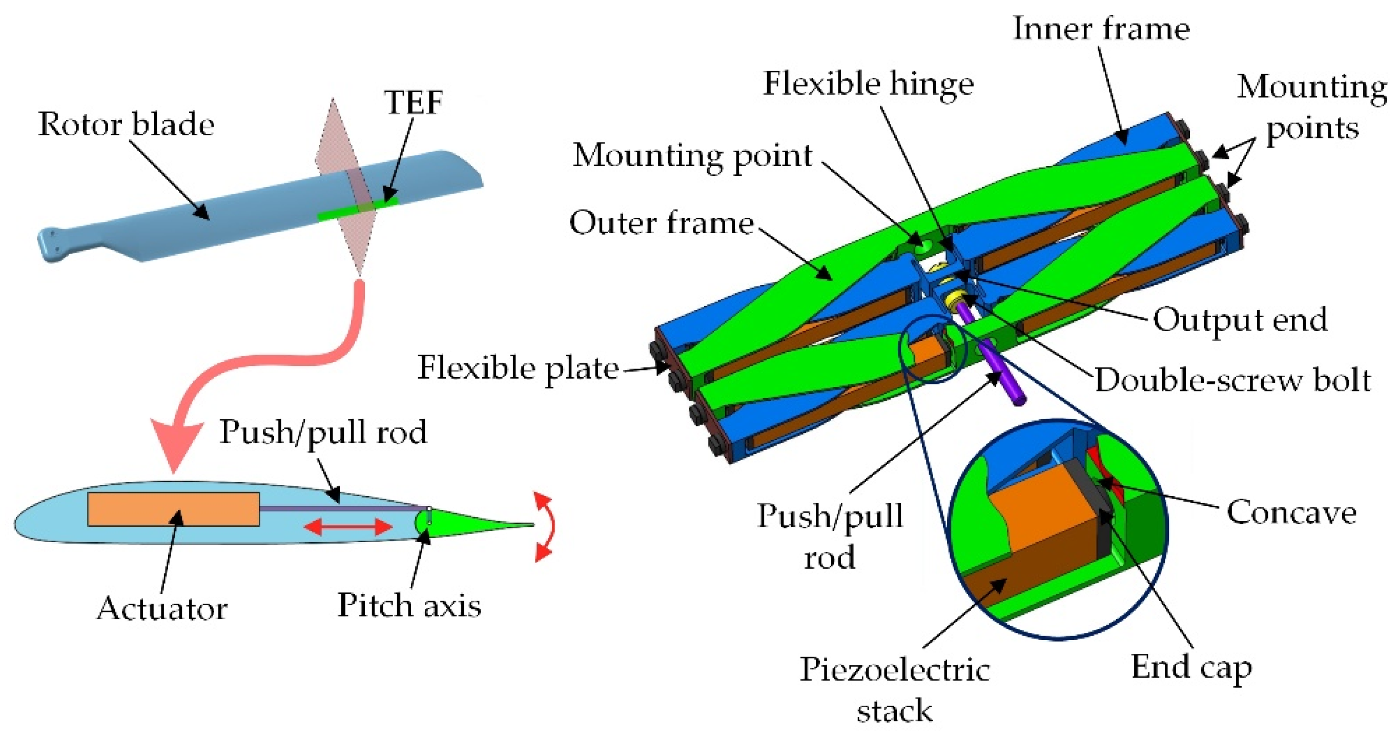
2. Structure and Operating Principle

2.1. Structure of the Double-Acting Actuator

The structure of a rotor blade with a TEF and an isometric view of the proposed actuator is represented in Figure 1. As can be seen, the TEF is mounted on the trailing-edge of a rotor blade, and an actuator embedded in the blade drives this TEF through a push/pull rod. The deflection motion of the TEF can change the aerodynamics of the blade and consequently manipulates its aero-elastic responses. If the TEF is excited by properly prescribed control signals, active vibration or noise control can be achieved.
The proposed actuator consists of eight piezoelectric stacks, two inner frames, two outer frames, and some necessary accessories (end caps, flexible plates, bolts, etc.). End caps are attached at both ends of the piezoelectric stacks. Each end cap is accommodated in a concave located on the inner frame or on the outer frame, constituting a hinge between the inner/outer frame and the piezoelectric stacks, which permits relative rotation between these two components. The outer frames, which are bolted to the blade through mounting points on them, are the stationary parts of the actuator, while the inner frames are its moving parts. A flexible plate, serving as a pivot, links an inner frame and an outer frame at their outboard ends. This plate allows the inner frame to rotate relative to the outer frame but maintains the constant distance between these two frames. At the inboard end of each inner frame, a flexible hinge, being the most distinct feature of this actuator, is used to connect the inner frame with the output end. A double-screw bolt, with a left-hand thread and right-hand thread at its two ends respectively, fastens the two output ends together. Compressive preloads applied to the piezoelectric stacks can also be adjusted through the rotation of the double-screw bolt. The push/pull rod, which is attached to the double-screw bolt, transfers the output stroke and force to the TEF.

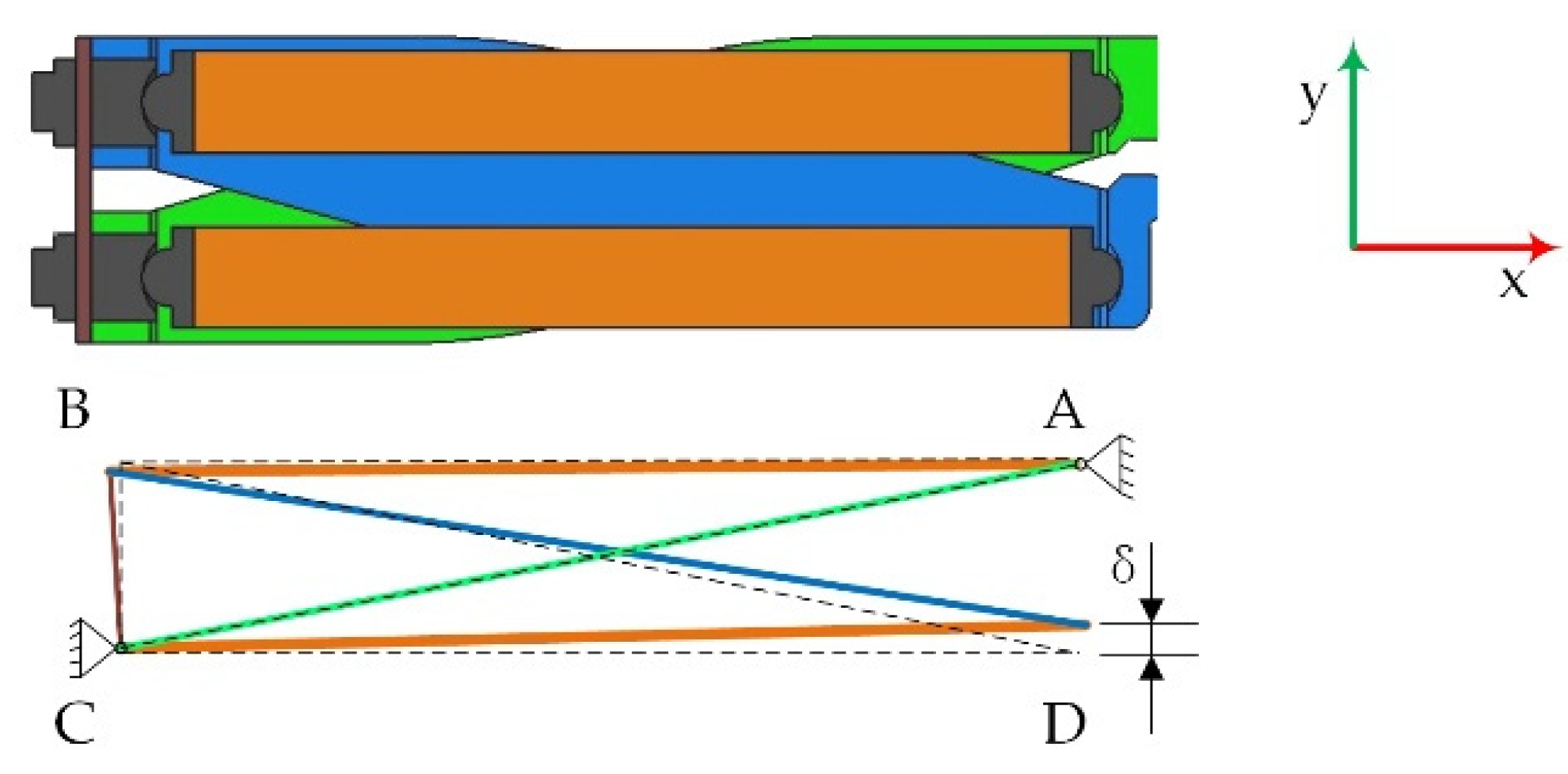
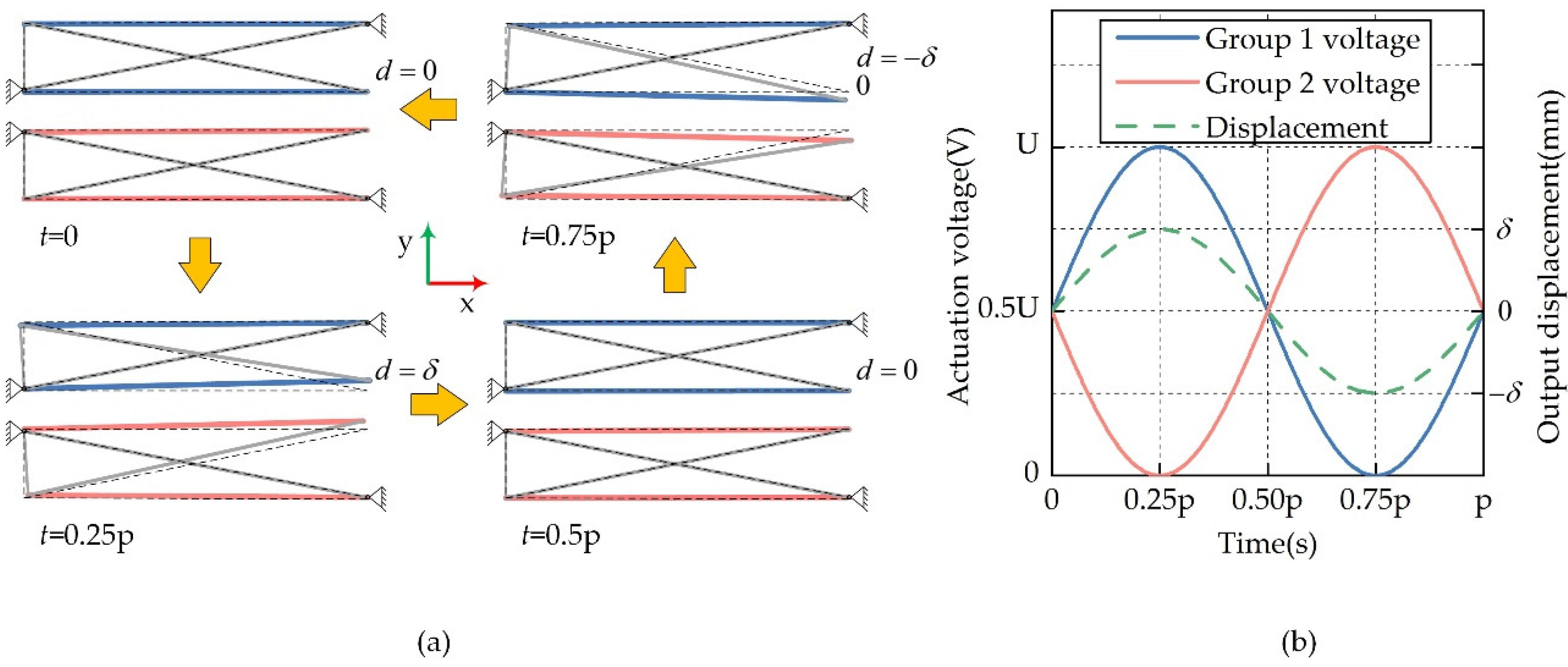
2.2. Operating Principle of the Double-Acting Actuator

The actuator can be divided into four X modules as shown in Figure 2. The piezoelectric stacks accommodated in each X module will stretch when voltages are applied to them. Since the lengths of outer frame AC, the inner frame BD and the flexible sheet BC remain constant, point D will move upward. This upward displacement is significantly higher than the elongations of the piezoelectric stacks due to the stroke amplification of the X module. The quantitative relationship between the applied voltage and the actuator output stroke will be given in the following section.
The eight piezoelectric stacks are electrically divided into two groups as shown in Figure 3. Only half of the actuator is represented in this figure to explain its operating principle because of its symmetry with respect to the axis of the push/pull rod. The voltages applied to the two groups of piezoelectric stacks are completely out of phase. When the applied voltage of Group 1 increases from 0.5 U to U, while the applied voltage of Group 2 decreases from 0.5 U to 0, the elongations of piezoelectric stacks in Group 1 drive the output end to move in the positive direction of the y-axis and to reach its maximum stroke of δ . In contrast, the decrease and increase of actuation voltages in Group 1 and Group 2, respectively, lead to the negative output stroke of this actuator. The two groups of piezoelectric stacks are subjected to alternating actuation voltages, consequently, the actuator yields double-acting output through the differential motion of them.
This actuator is inspired by Theodora’s X-frame actuator for an MD-900 helicopter rotor [24]. Considerable modifications have been made to improve the actuation performance. The three main improvements are as follows:
Firstly, the output end is connected to the inner frames through flexible hinges instead of the rolling contacts used in Theodora’s design. These flexible hinges are stiff in tensile direction but soft in bending direction. The output stroke and force are transferred from the inner frames to the output ends through the flexible hinges, while the lateral movement of the X modules, which is vertical to the output stroke, is compensated by the bending deformation of the flexible hinges. The flexible hinge simplifies the structure of the actuator and overcomes potential problems resulting from the mechanical clearance and friction of the rolling contacts.
Secondly, the number of piezoelectric stacks is doubled compared to the X-frame actuator, dramatically strengthening the actuation capability.
Finally, the number of mounting points between the actuator and rotor blade is increased to make the connection between them more stable and reliable.

3. Simulation Models and Structural Optimization

Structural design and optimization of the proposed actuator were carried out in this section. Firstly, a theoretical model was built for the fast assessment of the actuator’s free stroke. Secondly, a finite element model was established with structural details and material properties of the actuator taken into consideration. Finally, the influence of the actuator geometry on the actuator performance was studied using the finite element method (FEM). The thickness of the inner and the outer frames, as well as the flexible hinge at the output end, were optimized.

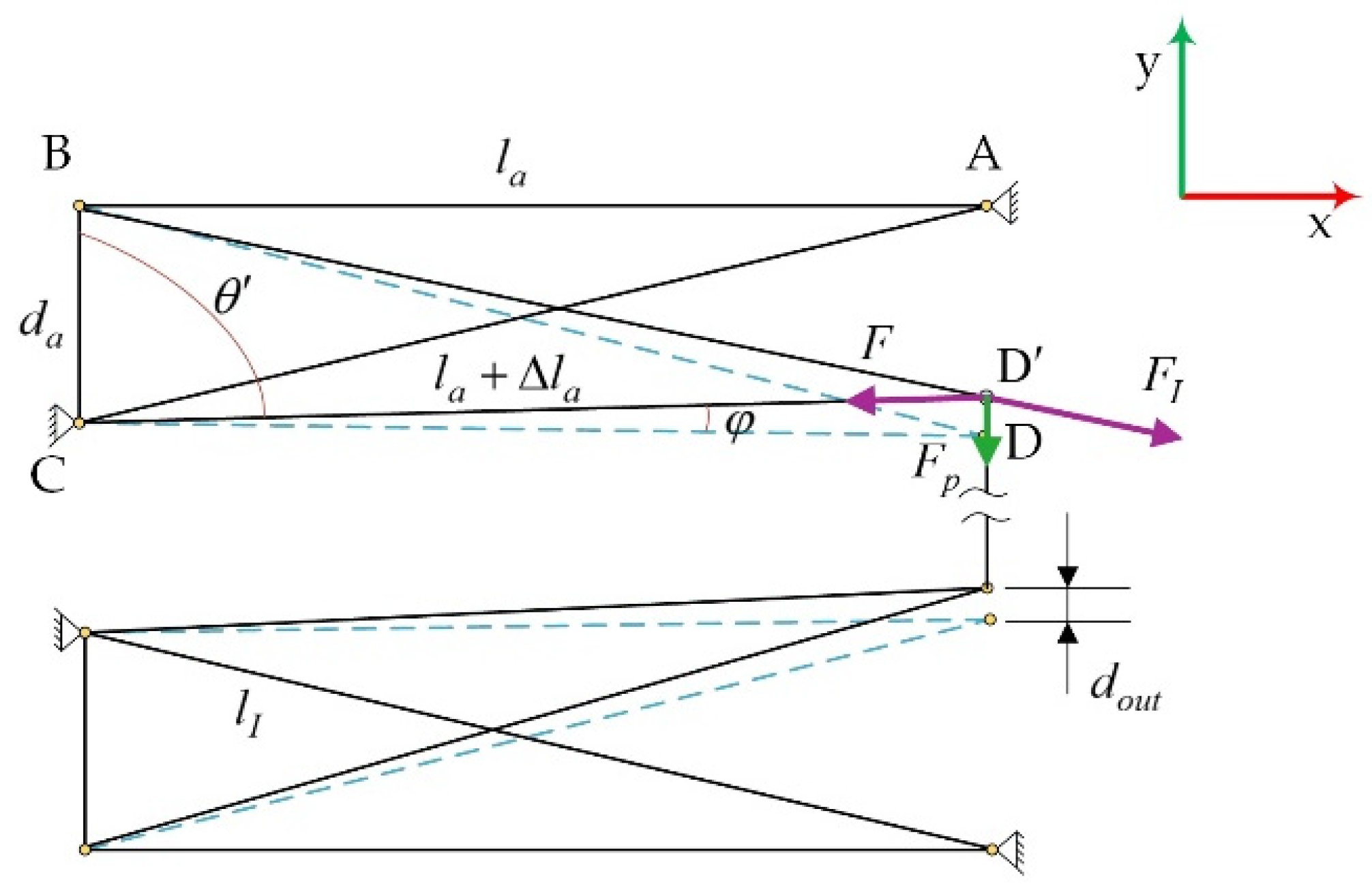
3.1. Theoretical Model of the Actuator

The simplified model of the X module is demonstrated in Figure 4. Considering that the elongations of piezoelectric stacks under applied actuation voltages are very small (The maximum longitudinal extension of a piezoelectric stack is about 1/1000 of its length), the following assumptions are made for the X module to simplify the modeling process:
(1)
The position of point B does not change with the variation of actuation voltage;
(2)
BCD remains constant at 90 degrees;
(3)
The lengths of the inner frame BD and the outer frame AC stay the same, and their compliance is neglected.
For triangle B C D , the cosine of θ can be expressed as:
cos ( θ ) = sin ( φ ) = d a 2 + ( l a + Δ l a ) 2 l I 2 2 d a ( l a + Δ l a )
where, d a is the distance between the inner frame and the outer frame at the outboard end, l a is the initial length of a piezoelectric stack with end caps attached on both ends, Δ l a is the elongation of a piezoelectric stack under actuation voltage, and l I is the length of the inner frame and the outer frame. The output stroke of the actuator can be calculated by:
d o u t = l a sin ( φ )
Given that the elongations of stacks are small enough to be negligible, the amplification ratio of the X module is approximately equal to:
r a m p = d o u t Δ l a = l a 2 d a ( l a + Δ l a ) l a d a
The actuation voltages applied to the two groups of piezoelectric stacks are:
u 1 = u b + u 0 P sin ( 2 π f t )
u 2 = u b + u 0 P sin ( 2 π f t + π )
where, u b is the bias voltage, and u 0 P is the 0-p amplitude of actuation voltages. For a piezoelectric stack subjected to actuation voltage and external load simultaneously, taking a stack of Group 1 as an example, its strain in the lengthwise direction can be expressed as:
ε 1 = d 33 E + s 33 T = d 33 u 1 t p + s 33 F s p
In this equation, d 33 is the converse piezoelectric coefficient, E is the electric field strength applied to the piezoelectric material, s 33 is the flexible coefficient, T is the normal stress on the cross section of the piezoelectric stack, t p is the thickness of each layer of the piezoelectric material, s p is the cross-sectional area of the piezoelectric stack. Considering that only the maximum elongation Δ l m a x (when subjected to a maximum actuation voltage of u m a x ) and the stiffness of the piezoelectric stacks k p are given, instead of detailed material properties, then the equivalent converse piezoelectric coefficient d = d 33 t p = Δ l m a x l p u m a x and the equivalent flexible coefficient s = s 33 s p = 1 k p l p are introduced. After that, Equation (5) can be rewritten as:
ε 1 = d u 1 + F k p l p
With external loads and actuation voltages applied to the X modules, the induced strains of the piezoelectric stacks can be evaluated as:
ε 1 = d u 1 F p r a m p k p l p
ε 2 = d u 2 F p r a m p k p l p
Since that the resultant strain of the piezoelectric stacks in Group 1 is opposite to that of Group 2, the output stroke of this actuator can be obtained by combining Equation (8) with Equation (9):
d o u t = l p l a d ( u 1 u 2 ) d a = 2 l p l a d u 0 p sin ( 2 π f t ) d a

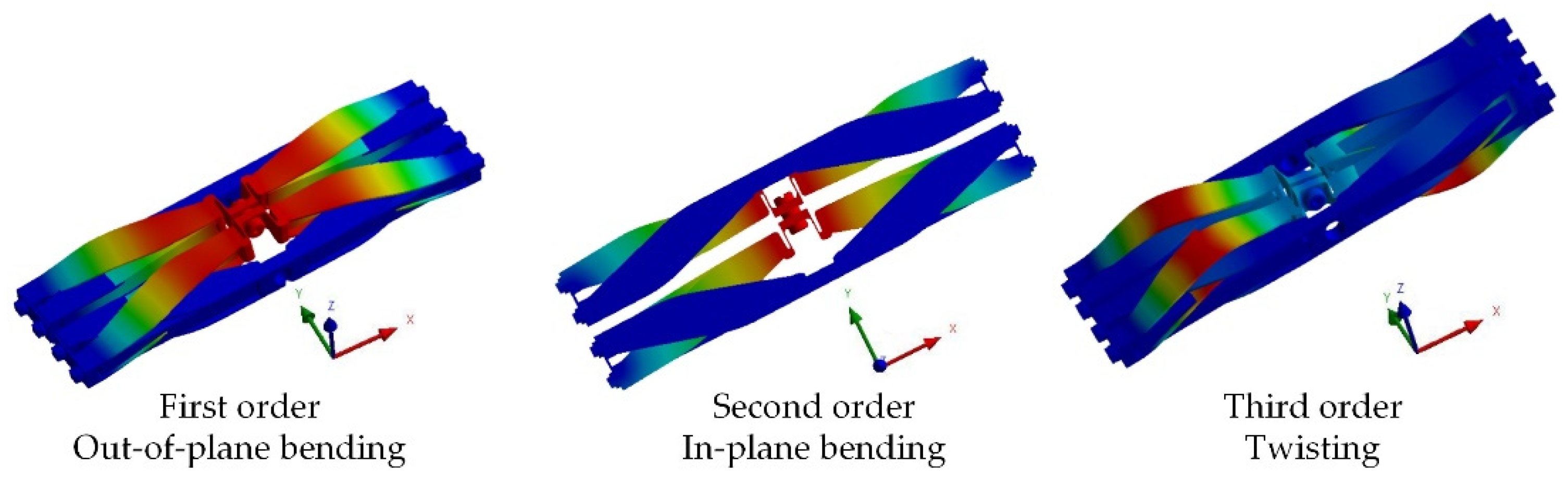
3.2. Finite Element Model of the Actuator

Using the theoretical model, basic geometric parameters of the actuator, including the length of the piezoelectric stack l a and the distance between the inner frame and the outer frame d a , were determined to fulfill the stroke requirement for trailing-edge flap application. After that, a prototype of the proposed actuator was designed, and a finite element model was established using commercial finite element software. For material selection, the inner and outer frames were made of titanium alloy (TC4) to reduce the mass of the actuator, and accessory parts, such as the end caps and the screws, were made of alloy steel (30CrMnSiA) to alleviate compliance which can lead to a loss in output stroke. The material properties are listed in Table 1.
It is difficult to directly model the piezoelectric stack using the finite element method (FEM). Firstly, the piezoelectric stack is composed of multiple layers of piezoelectric material and electrodes inserted between every two layers. The thickness of an individual layer is on the order of 100 μm and its polarization direction is opposite to the adjacent layer. Thus, directly modeling each layer of the piezoelectric material will significantly increase the number of elements and reduce the computational efficiency. Secondly, the manufacturer does not provide the detailed material properties of the stacks, instead, they give parameters such as the geometrical size, maximum elongation, and stiffness in the lengthwise direction. Therefore, the thermal analogy method was used to model the piezoelectric stacks in this study. For this method, the piezoelectric stack was assumed to be homogeneous, and its multi-layer structure, as well as the metal electrodes, were neglected. The stack can generate thermal expansion when applied to the thermal load, and the piezoelectric stain of the stack was analogized by this thermal expansion.
The strain of piezoelectric material resulting from thermal load can be expressed as:
ε T = [ α 11 α 22 α 33 α 23 α 31 α 12 ] T T
where, α is the thermal strain component, and T is the thermal load applied to the material. The piezoelectric strain is given by:
ε E = [ d 31 d 32 d 33 0 0 0 ] T u t p
In this equation, d is the piezoelectric strain component, u is the voltage applied to the piezoelectric layer with a thickness of t p . Equations (11) and (12) imply that the piezoelectric strain can be analogized by the thermal expansion strain. The piezoelectric strain in the lengthwise direction is given as an example:
α 33 T = d 33 u t p = d e u
An equivalent converse piezoelectric coefficient d e = d 33 / t p was introduced in Equation (13). Let T = u , and then α 33 = d e . A PTJ1500707701 stack produced by Pant was simulated and analyzed using the thermal analogy method in the FEM software. Its nominal values and the corresponding FEM simulation results are presented in Table 2. The comparison results show that this method can accurately simulate the properties of the stack.
An FEM model of the proposed actuator was established. Geometric details, including chamfer and round features, were retained in the modeling process. The mesh quality was fine with a maximum element size of no more than 1.0 mm. To predict stress distribution in the flexible hinges more precisely, meshes in these components were refined further and material properties were set according to Table 1. As the actuator will be installed close to the blade tip, it will be subjected to a large centrifugal load during rotor operation. For this reason, a rotation speed of Ω = 1050   RPM was applied to the actuator model in FEM simulation, and the actuator was set 2 m away from the center of rotation. According to the operating principle of this actuator, when the stacks of Group 1 are subjected to a thermal load equivalent to an actuation voltage of 150 V, and the stacks of Group 2 are subjected to a thermal load of 0 V, this actuator will generate output stroke in the positive direction of the y-axis. Alternating the thermal loads applied to these two groups of stacks will induce output stroke in the negative direction of the y-axis.
The results of the stress analysis (Figure 5) show that, when the output end of the actuator moves to its extreme position under the maximum actuation voltage of 150 V, significantly high stresses occur in the flexible hinges. These stresses mainly result from the bending deformation of the flexible hinges. This actuator is designed to operate in dynamic conditions, hence the induced alternating stresses in the flexible hinges will impose a negative effect on its fatigue life.
Modal analysis was carried out, and the modes of the first three orders are shown in Figure 6. The first one is denoted as the out-of-plane bending mode, in which the inner frames of this actuator oscillate vertically to the x-y plane. The second one is called the in-plane bending mode, in which the inner frames vibrate along the y-axis. The third one is the twisting mode with the inner frames twisting with respect to the y-axis. The modal frequencies of these three modes should be higher than the operating frequencies of this actuator to guarantee an adequate working bandwidth. In the following sections, the influence of geometric parameters on modal frequencies will be studied.

3.3. Structural Optimization for the Actuator

In this section, the influence of the thicknesses of the inner/outer frames and the flexible hinges on the actuator performance was investigated using the FEM method. The optimal values were determined by comprehensively considering various factors, including the output stroke, the actuator stiffness, the stress in the flexible hinges, and the modal frequencies.

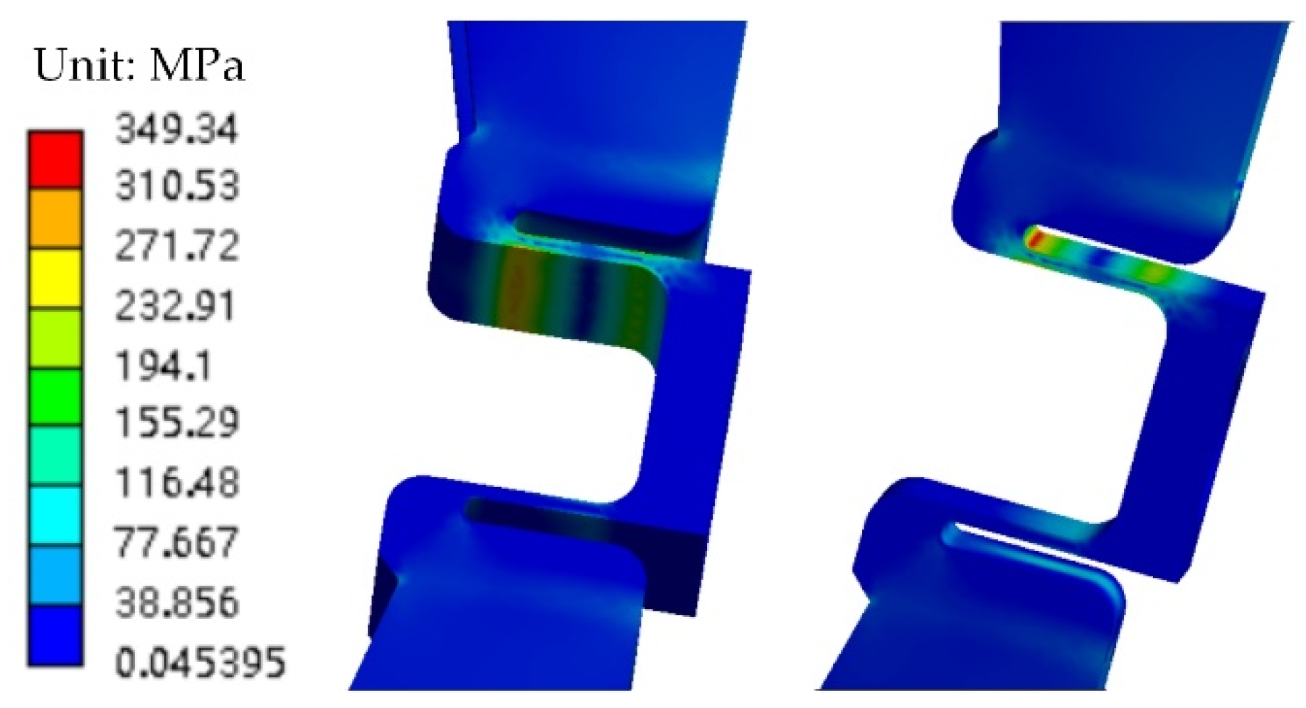
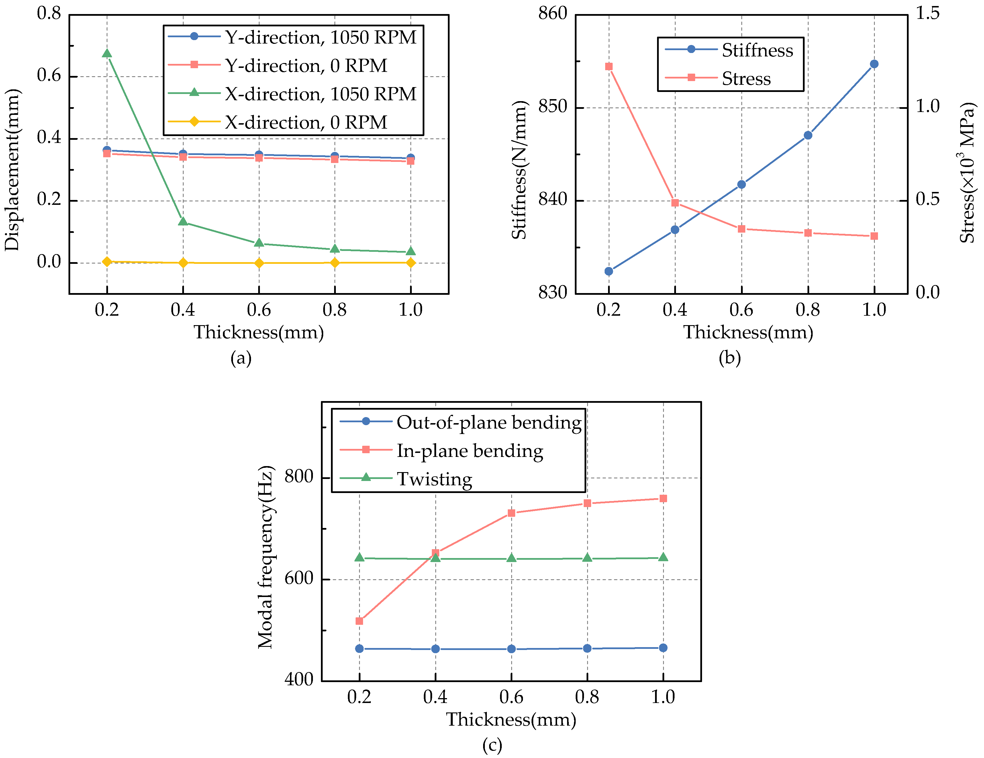
3.3.1. Thickness of Flexible Hinges

A series of FEM models of this actuator was established with the thickness of flexible hinges set to 0.2 mm, 0.4 mm, 0.6 mm, 0.8 mm, and 1.0 mm, respectively. The simulation results are represented in Figure 7.
As shown in Figure 7a, the output stroke of this actuator reaches about 0.34 mm when subjected to a thermal load equivalent to an actuation voltage of 150 V. The output stroke decreases slightly with the increase of the flexible hinge thickness, resulting from the increased bending stiffness of the flexible hinges, which can hinder the output of this actuator to some extent.
Displacements of the output end in the x-axis direction, denoted as the lateral displacement in this work, and occur in the presence of centrifugal load. The amplitude of these lateral displacements can exceed the normal output stroke of this actuator if the flexible hinges are not thick enough, however, it decreases rapidly with the increase of the flexible hinge thickness.
The actuator stiffness in the output direction (y-axis) grows up with the increase of flexible hinge thickness as shown in Figure 7b. Higher stiffness is desired because the passive compliance of the actuator resulting from external loads will be smaller. At the same time, the maximum stress of the flexible hinges drops with the increase in flexible hinge thickness.
Figure 7c shows that the modal frequency of the in-plane bending mode is sensitive to the variation of flexible hinge thickness, while the modal frequencies of other modes are insensitive. Fortunately, all these modal frequencies are above 400 Hz, which is far higher than the operating frequencies of this actuator.
Comprehensively considering the output stroke, the stiffness and the maximum stress in flexible hinges, the optimal range of the flexible hinge thickness is between 0.6 mm to 0.8 mm. Exceeding this range, the lateral displacement of the output ends and the maximum stresses in the flexible hinges will become insensitive to the variation of the thickness, and further increasing the flexible hinge thickness will be inefficient.

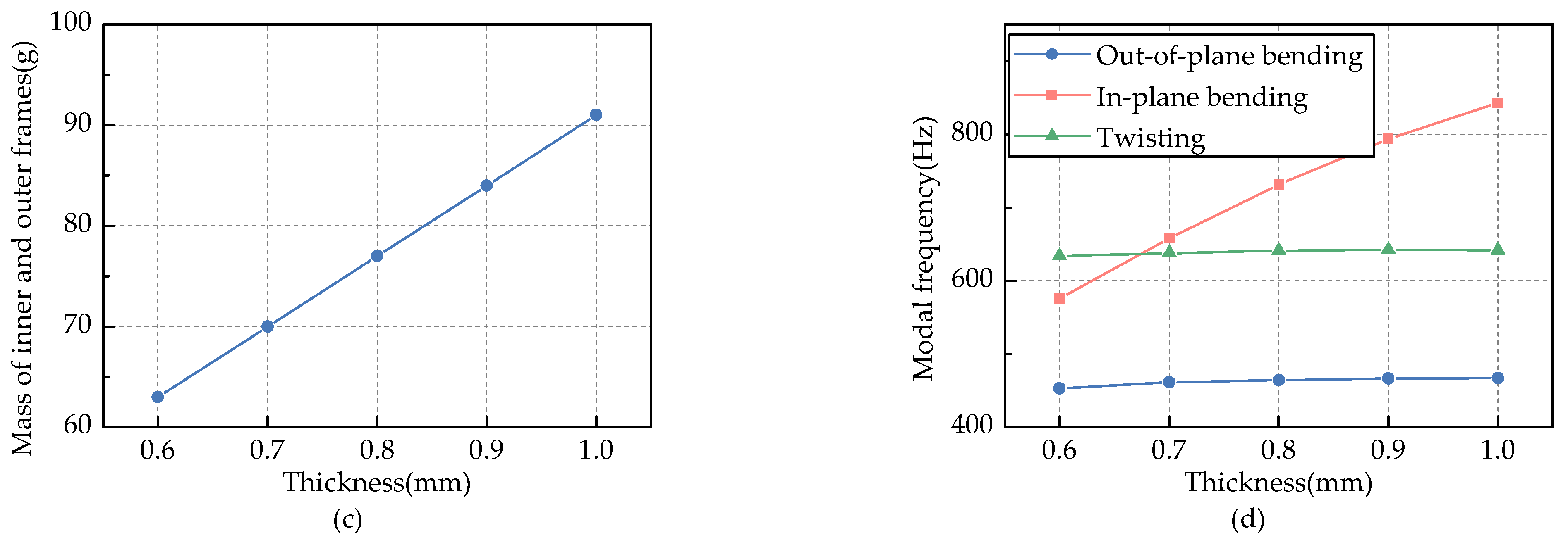
3.3.2. Thickness of Inner/Outer Frames

FEM models with thicknesses of the inner/outer frames ranging from 0.6 mm to 1.0 mm were built. The influence of frame thickness on the performance of this actuator is shown in Figure 8.
Figure 8a demonstrates that the output stroke of the actuator increases slightly with the increase of frame thickness. Larger thickness improves the tensile and bending stiffnesses of the inner/outer frames, which can alleviate the compliance of the amplification mechanism. The lateral displacement of the output ends is insensitive to the variation of the frame thickness. This is because the output ends are relatively independent of the frames and their lateral displacement is mainly due to their own centrifugal load.
As shown in Figure 8b, the stiffness of the actuator increases significantly with the increase of the frame thickness, meanwhile, the maximum stress in the flexible hinges is insensitive to the variation of the frame thickness. Increasing the frame thickness is beneficial to improve the stiffness of this actuator, however, it will dramatically increase the mass of the frames as shown in Figure 8c.
The variation of the frame thickness has a great influence on the modal frequency of the in-plane bending mode, while its influence on the other two modes is minor, as shown in Figure 8d. Fortunately, the first three orders of the modal frequencies are above 400 Hz, which is much higher than the operating frequency of this actuator.
With the stiffness and the mass of the actuator taken into consideration, the frame thickness should be about 0.8 mm to achieve an acceptable actuator stiffness and a minor actuator mass.

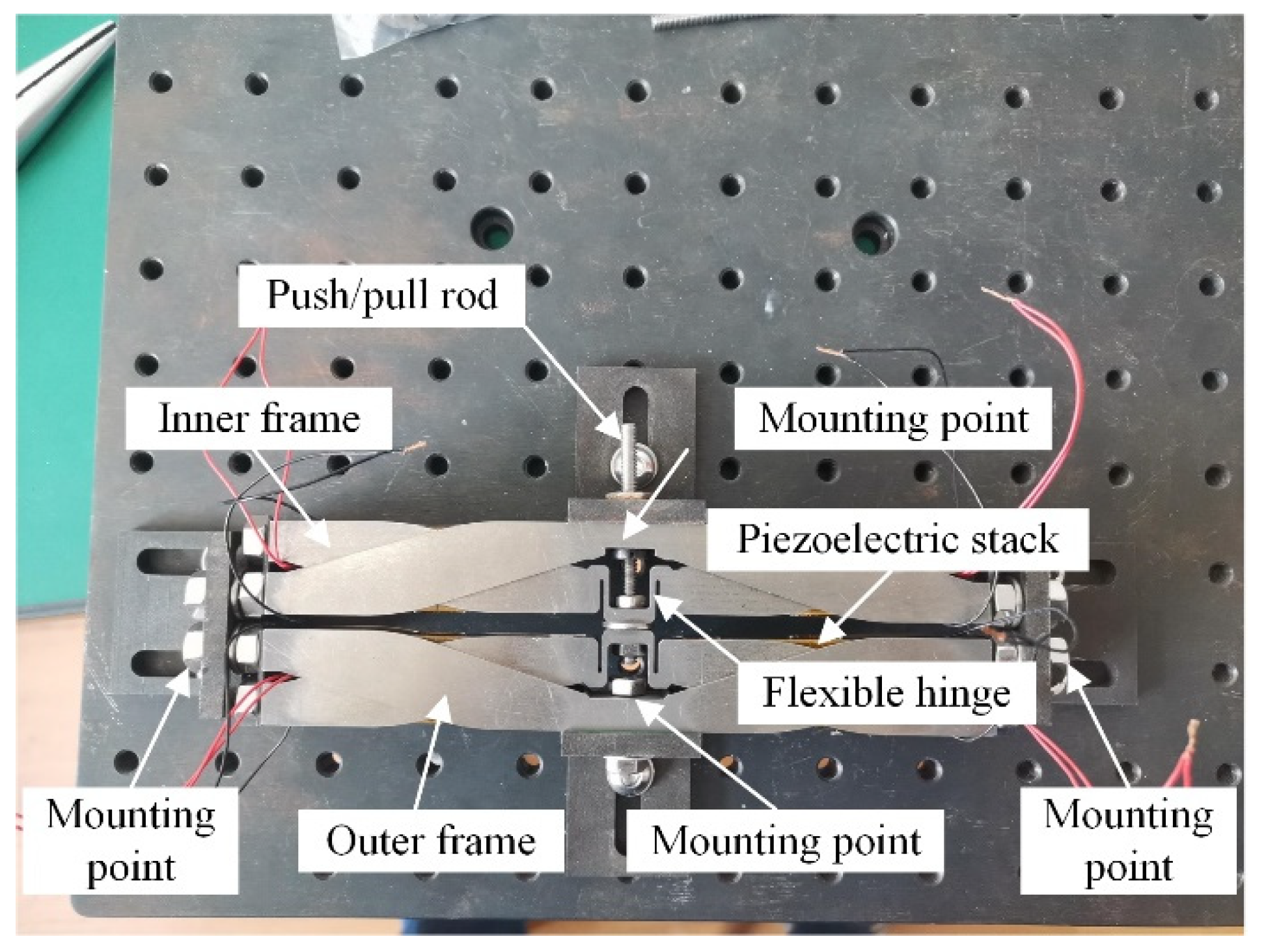
4. Benchtop Tests of the Actuator Prototype

Based on the results of the structural optimization, a prototype of the proposed actuator, as shown in Figure 9, was manufactured and assembled.
Benchtop tests were carried out to assess the performance of the actuator prototype. The equipment used in the tests is shown in Figure 10. A controller (NI myRIO 1900) capable of generating and acquiring analog signals was used to generate two control signals, which were completely out-of-phase. These control signals were amplified by a power amplifier before they were applied to the piezoelectric stacks. Although the selected piezoelectric stacks in this study can withstand voltages up to 150 V, the maximum actuation voltage in the benchtop tests was set to 120 V for safety. A laser displacement sensor (Panasonic HL-G103-A-C5) was utilized to measure the output stroke of the actuator, which was logged by the controller. The resolution of this sensor was 0.5 μm, and the linearity is ±0.1%F.S.
Firstly, the stiffness of the actuator was evaluated as shown in Figure 11. External loads were applied to the actuator by hanging weights on the push/pull rod. The average stiffness of multiple measurements was 801 N/mm for the actuator prototype, while the FEM simulation result was 842 N/mm. The error mainly comes from the machining error of the frames. It was found that the thickness of one of the inner frames was lower than the design value of 0.8 mm. Since that the actuator stiffness is sensitive to the frame thickness, which has been validated by the FEM simulation, necessary measures should be taken in the manufacturing processes to improve its actuation performance further.
Secondly, the output strokes of this actuator prototype were measured in quasi-steady conditions. Control signals of a low frequency (0.5 Hz) were generated to drive the actuator. This test was aimed to assess the amplitude of its output stroke and to verify the accuracy of the theoretical model and the FEM model established in the former section. As shown in Table 3, this actuator was capable to generate double-acting output and its output stroke reached ±0.27 mm. Both the Theoretical model and the FEM model can precisely predict the output strokes of this actuator. The maximum error between the theoretical model and the measurement results is 0.016 mm, while it is 0.019 mm for the FEM model. Nevertheless, it should be noted that neither of these two models has taken the hysteresis characteristics of the piezoelectric stacks into consideration, as a result, these two models did not capture the hysteresis features of this actuator prototype. Its hysteresis phenomenon will be studied in the next stage of the study.
Finally, the dynamic performance of this actuator was tested with the actuator subjected to actuation signals of different frequencies. The frequency range was set from 1 Hz to 70 Hz, which covered the operating frequencies of this actuator. The measured output strokes are shown in Figure 12a,b. As can be seen, for low actuation frequencies, the hysteresis loops were almost identical to each other. The hysteresis behavior became more significant with the increase of the actuation frequency, but the degradation in the output stroke was minor. The actuator output stroke still reached about ±0.25 at the frequency of 70 Hz. Piezoelectric stack failure was also simulated in this study by canceling the actuation voltage applied to the stacks of Group 2. The actuator output strokes in this condition are demonstrated in Figure 12c. Although the output stroke was reduced to half of the normal value, the actuator could still function and produce acceptable output in this condition. In addition, the initial position of the actuator without actuation voltages remained unchanged, which meant that actuator failure would not change the initial position of trailing-edge flaps and therefore the primary control of the helicopter rotor. This is a great advantage over the other types of piezoelectric actuators, which could only generate single-acting output.

5. Conclusions

A compact, high-performance piezoelectric actuator was proposed for active rotor applications. This actuator was capable of double-acting output. A theoretical model and a FEM model were established to design and optimize this actuator. A prototype was manufactured and assembled, and then both quasi-steady and dynamic tests were conducted on benchtop to evaluate its performance. Several conclusions were obtained as follows:
(1)
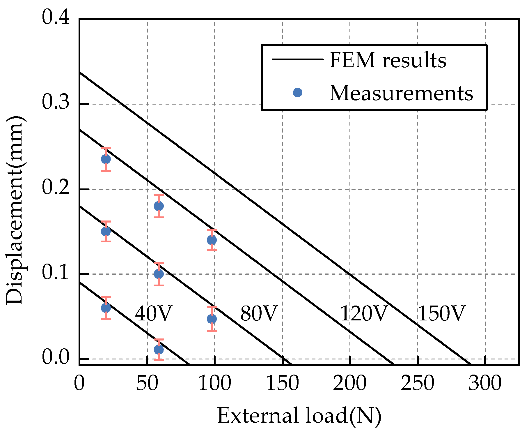
The theoretical model and the FEM model established in this study could precisely predict the output stroke of the actuator. The maximum error between the theoretical model outputs and the experimental measurements was 0.016 mm, while it was 0.019 mm for the FEM model. The theoretical model was capable of determining the primary parameters of this actuator, while the FEM model could be utilized to perform structural optimization.
(2)
The output stroke of this actuator reached ±0.27 mm when subjected to actuation voltages of 120 V and a high stiffness of 801 N/mm was achieved, which is important to alleviate the negative deflection of TEFs resulting from external loads.
(3)
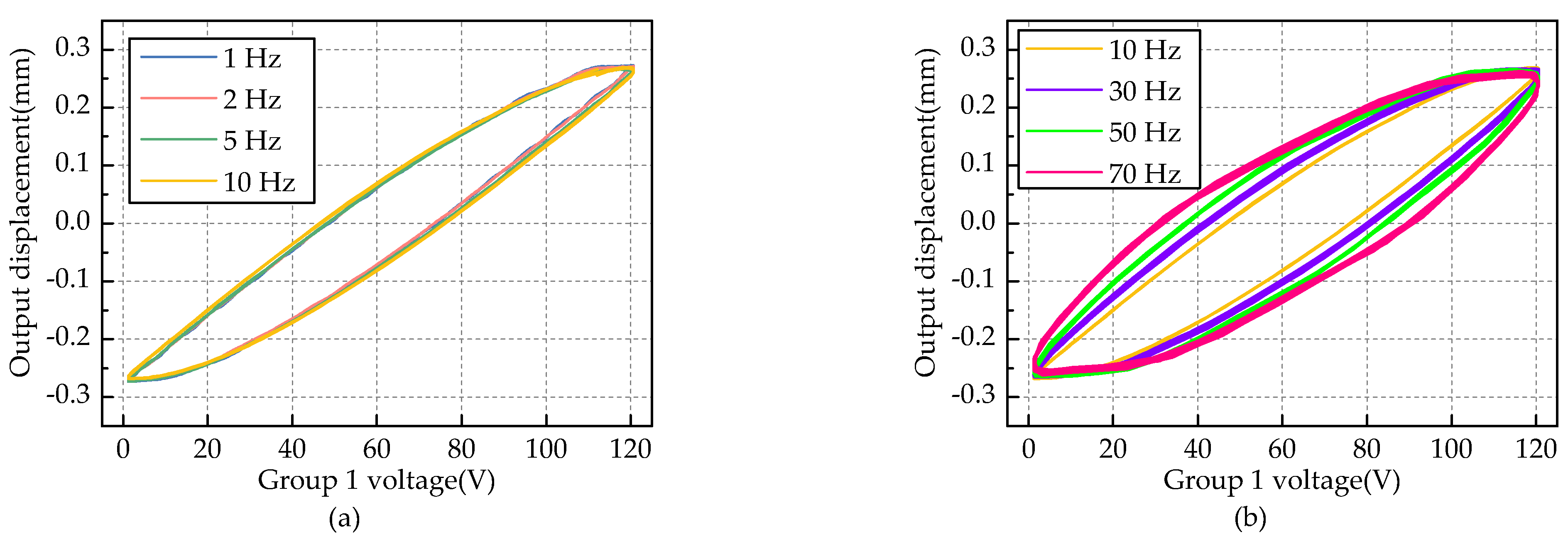
Even though the hysteresis of this piezoelectric actuator increased with the increase of actuation frequency, the degradation in the output stroke was minor. The actuator could still generate a free stroke of about ±0.25 mm at the frequency of 70 Hz, demonstrating a wide operating bandwidth of this actuator and its capability to drive an active rotor with high rotational speed.
(4)
The actuator could still produce an acceptable output when some piezoelectric stacks failed, and the initial position of the output ends remained unchanged in this condition, consequently, the aerodynamic balance of the helicopter rotor was not influenced in presence of piezoelectric stack failure.

Author Contributions

Conceptualization, W.Y.; methodology, J.Z. and L.D.; writing—original draft preparation, J.Z.; writing—review and editing, L.D.; supervision, W.Y.; project administration, W.Y.; funding acquisition, W.Y. All authors have read and agreed to the published version of the manuscript.

Funding

This research was funded by the Priority Academic Program Development of Jiangsu Higher Education Institutions (PAPD).

Institutional Review Board Statement

Not applicable.

Informed Consent Statement

Not applicable.

Data Availability Statement

Data can be available from the corresponding authors.

Conflicts of Interest

The authors declare no conflict of interest.

References

  1. Friedmann, P.P. On-blade control of rotor vibration, noise, and performance: Just around the corner? J. Am. Helicopter Soc. 2014, 59, 1–37. [Google Scholar] [CrossRef]
  2. Enenkl, B.; Klöppel, V.; Preißler, D.; Jänker, P. Full scale rotor with piezoelectric actuated blade flaps. In Proceedings of the 28th Annual Forum of the European Rotorcraft Forum, Bristol, UK, 17–19 September 2002; Royal Aeronautical Society: London, UK, 2002. [Google Scholar]
  3. Dieterich, O.; Enenkl, B.; Roth, D. Trailing edge flaps for active rotor control aeroelastic characteristics of the ADASYS rotor system. In Proceedings of the 62nd Annual Forum of the American Helicopter Society, Phoenix, AZ, USA, 9–11 May 2006; AHS International: Fairfax, VA, USA, 2006; pp. 964–985. [Google Scholar]
  4. Padthe, A.K.; Friedmann, P.P. Simultaneous BVI noise and vibration reduction in rotorcraft using microflaps including the effect of actuator saturation. In Proceedings of the 68th Annual Forum of the American Helicopter Society, Fort Worth, TX, USA, 1–3 May 2012; AHS International: Fairfax, VA, USA, 2012; pp. 1316–1338. [Google Scholar]
  5. Hall, S.R.; Prechtl, E.F. Development of a piezoelectric servoflap for helicopter rotor control. Smart Mater. Struct. 1996, 5, 26–34. [Google Scholar] [CrossRef]
  6. Woods, B.K.S.; Kothera, C.S.; Wereley, N.M. Whirl testing of a pneumatic artificial muscle actuation system for a full-scale active rotor. J. Am. Helicopter Soc. 2014, 59, 1–11. [Google Scholar] [CrossRef]
  7. Jänker, P.; Christmann, M.; Hermle, F.; Lorkowski, T.; Storm, S. Mechatronics using piezoelectric actuators. J. Eur. Ceram. Soc. 1999, 19, 1127–1131. [Google Scholar] [CrossRef]
  8. Lorber, P.; Neill, J.J.; Isabella, B.; Wake, B.E.; Jonsson, U.; Sun, F. Whirl test of a large scale high authority active flap rotor. In Proceedings of the 66th Annual Forum of the American Helicopter Society, Phoenix, AZ, USA, 11–13 May 2010; AHS International: Fairfax, VA, USA, 2010; pp. 2572–2858. [Google Scholar]
  9. Lorber, P.; Neill, J.J.; Hein, B.; Isabella, B.; Andrews, J.; Brigley, M.; Wong, J.; LeMasurier, P.; Wake, B. Whirl and wind tunnel testing of the Sikorsky active flap demonstration rotor. In Proceedings of the 67th Annual Forum of the American Helicopter Society, Virginia Beach, VA, USA, 3–5 May 2011; AHS International: Fairfax, VA, USA, 2011; pp. 3138–3156. [Google Scholar]
  10. Myasnikov, M.I.; Esaulov, S.Y.; Filenkov, E.V.; IIyin, I.R. Actively controlled trailing edge flaps with electromechanical actuation. In Proceedings of the 44th Annual Forum of European Rotorcraft Forum, Delft, The Netherlands, 19–20 September 2018; Netherlands Association of Aeronautical Engineers: Amsterdam, The Netherlands, 2018; pp. 1334–1341. [Google Scholar]
  11. Li, J.F.; Zhang, X.B. Active flow control for supersonic aircraft: A novel hybrid synthetic jet actuator. Sens. Actuator A Phys. 2020, 302, 111770. [Google Scholar] [CrossRef]
  12. Vo, T.V.K.; Lubecki, T.M.; Chow, W.T.; Gupta, A.; Li, K.H.H. Large-scale piezoelectric-based systems for more electric aircraft applications. Micromachines 2021, 12, 140. [Google Scholar] [CrossRef]
  13. Hu, K.M.; Li, H. Multi-parameter optimization of piezoelectric actuators for multi-mode active vibration control of cylindrical shells. J. Sound Vib. 2018, 426, 166–185. [Google Scholar] [CrossRef]
  14. Selim, S.; Fevzi, C.B.; Ercan, E. Active vibration control of a blade element with uncertainty modeling in PZT actuator force. J. Vib. Control. 2019, 25, 2721–2732. [Google Scholar] [CrossRef]
  15. Koratkar, N.A.; Chopra, I. Analysis and testing of a Froude scaled helicopter rotor with piezoelectric bender actuated trailing edge flaps. J. Intell. Mater. Syst. Struct. 1997, 8, 555–570. [Google Scholar] [CrossRef]
  16. Koratkar, N.A.; Chopra, I. Analysis and testing of Mach-scaled rotor with trailing-edge flaps. AIAA. J. 2000, 38, 1113–1124. [Google Scholar] [CrossRef]
  17. Koratkar, N.A.; Chopra, I. Wind tunnel testing of a smart rotor model with trailing-edge flaps. J. Am. Helicopter Soc. 2002, 47, 263–272. [Google Scholar] [CrossRef]
  18. Fulton, M.V.; Ormiston, R.A. Hover testing of a small-scale rotor with on-blade elevons. J. Am. Helicopter Soc. 2001, 46, 96–106. [Google Scholar] [CrossRef]
  19. Fulton, M.V.; Ormiston, R.A. Small-scale rotor experiments with on-blade elevons to reduce blade vibratory loads in forward flight. In Proceedings of the 54th Annual Forum of the American Helicopter Society, Washington, DC, USA, 20–22 May 1998; AHS International: Fairfax, VA, USA, 1998; pp. 1348–1365. [Google Scholar]
  20. Roth, D.; Enenkl, B.; Dieterich, O. Active rotor control by flaps for vibration reduction-full scale demonstrator and first flight test results. In Proceedings of the 32nd Annual Forum of the European Rotorcraft Forum, Maastricht, The Netherlands, 12–14 September 2006; National Aerospace Laboratory: Amsterdam, The Netherlands, 2006; pp. 801–813. [Google Scholar]
  21. Rabourdin, A.; Maurice, J.B.; Dieterich, O.; Konstanzer, P. Blue Pulse active rotor control at Airbus Helicopters—New EC145 demonstrator and flight test results. In Proceedings of the 70th Annual Forum of the American Helicopter Society, Montreal, QC, Canada, 20–22 May 2014; AHS International: Fairfax, VA, USA, 2014; pp. 679–802. [Google Scholar]
  22. Lee, T.; Chopra, I. Design of piezostack-driven trailing-edge flap actuator for helicopter rotors. Smart Mater. Struct. 2001, 10, 15–24. [Google Scholar] [CrossRef]
  23. Crozier, P.; Leconte, P.; Delrieux, Y.; Gimonet, B.; Pape, A.L.; Rochettes, H.M. Wind-tunnel tests of a helicopter rotor with active flaps. In Proceedings of the 32nd Annual Forum of the European Rotorcraft Forum, Maastricht, The Netherlands, 12–14 September 2006; National Aerospace Laboratory: Amsterdam, The Netherlands, 2006; pp. 235–250. [Google Scholar]
  24. Tzianetopoulou, T. Design of an Improved Piezoelectric Actuator for Helicopter Rotor Control. Ph.D. Thesis, Massachusetts Institute of Technology, Cambridge, MA, USA, 2001. [Google Scholar]
  25. Straub, F.K.; Kennedy, D.K.; Stemple, A.D.; Anand, V.R.; Birchette, T.S. Development and whirl tower test of the SMART active flap rotor. In Proceedings of the SPIE-The International Society for Optical Engineering, San Diego, CA, USA, 14–18 March 2004; SPIE: Washington, DC, USA, 2004; pp. 1–11. [Google Scholar] [CrossRef]
  26. Straub, F.K.; Anand, V.R.; Birchette, T.S.; Lau, B.H. Smart rotor development and wind tunnel test. In Proceedings of the 35th Annual Forum of the European Rotorcraft Forum, Hamburg, Germany, 22–25 September 2009; DGLR: Berlin, Germany, 2009; pp. 413–434. [Google Scholar]
  27. Stacey, S.; Connolly, N.; Court, P.; Allen, J.; Monteggia, C.; Oliveros, J.M. Leonardo helicopters active rotor programmes to improve helicopter comfort & performance. In Proceedings of the 74th Annual Forum of the American Helicopter Society, Phoenix, AZ, USA, 14–17 May 2018; Vertical Flight Society: Fairfax, VA, USA, 2018; pp. 2866–2882. [Google Scholar]
Figure 1. Structure of the double-acting piezoelectric actuator.
Actuators 10 00247 g001
Figure 2. X module and its truss model.
Actuators 10 00247 g002
Figure 3. Operational principle of the actuator: (a) Output displacement of the actuator; (b) Actuation voltages of the piezoelectric stacks.
Actuators 10 00247 g003
Figure 4. Simplified model of the X module.
Actuators 10 00247 g004
Figure 5. Stress distribution of the flexible hinges.
Actuators 10 00247 g005
Figure 6. The first three order modal shapes of the actuator.
Actuators 10 00247 g006
Figure 7. The influence of the flexible hinge thickness on the actuator performance: (a) Displacement of the actuator; (b) Stiffness and structural stress of the actuator; (c) Modal frequencies of the actuator.
Actuators 10 00247 g007
Figure 8. The influence of the frame thickness on the actuator performance: (a) Displacement of the actuator; (b) Stiffness and structural stress of the actuator; (c) Mass of the frames; (d) Modal frequencies of the actuator.
Actuators 10 00247 g008aActuators 10 00247 g008b
Figure 9. Prototype of the actuator.
Actuators 10 00247 g009
Figure 10. Bench-top test of the actuator prototype.
Actuators 10 00247 g010
Figure 11. Output strokes under external loads.
Actuators 10 00247 g011
Figure 12. Output strokes of the actuator prototype in dynamic conditions: (a) Output displacement at low frequencies; (b) Output displacement at high frequencies; (c) Output displacement in presence of piezoelectric stack failure.
Actuators 10 00247 g012aActuators 10 00247 g012b
Table 1. Properties of mental materials used in the actuator.
MaterialYoung’s Modulus (GPa)Poisson’s RatioDensity (g/cm3)
TC41090.344.44
30CrMnSiA1960.307.75
Table 2. Nominal values of the piezoelectric stack and FEM simulation results.
ParameterNominal ValueFEM ResultError (%)
Dimensions (mm)7 × 7 × 60//
Mass (g)2424.110.46
Blocking force (N)18001702.655.41
Maximum stroke (mm)6867.970.04
Stiffness (N/μm)2525.050.2
Table 3. Comparison of free strokes between model outputs and experimental measurements.
Actuation Voltage (V)Theoretical Model (mm)FEM Model (mm)Measurements (mm)
0−0.2762−0.2682−0.2749
40−0.0921−0.0887−0.1079
800.09210.09080.0980
1200.27620.27040.2721
Publisher’s Note: MDPI stays neutral with regard to jurisdictional claims in published maps and institutional affiliations.

