
Axial Motion Characterization of a Helical Ionic Polymer Metal Composite Actuator and Its Application in 3-DOF Micro-Parallel Platforms

 , , ,
, , ,
Abstract
:1. Introduction
2. Materials and Methods
2.1. Materials
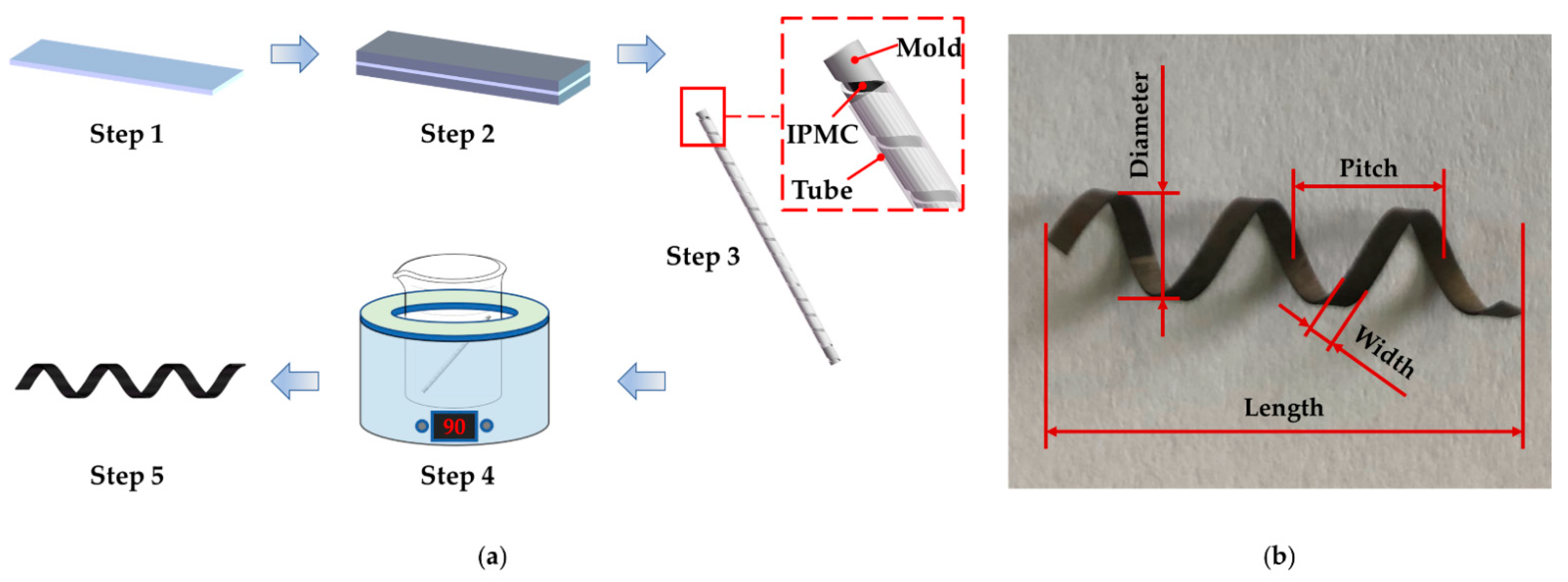
2.2. Fabrication
- Cut the commercial membrane Nafion-117 into a strip;
- Deposit platinum nanoparticles on both surfaces of the Nafion membrane by electroless plating to obtain an IPMC strip [31];
- Coil the IPMC strip in a prepared mold with helix grooves, and put a Teflon tube outside the mold to prevent the IPMC strip from expanding outward and releasing from the mold;
- Immerse the mold in deionized water at 90 °C for 5 h;
- Remove the helical IPMC from the mold.
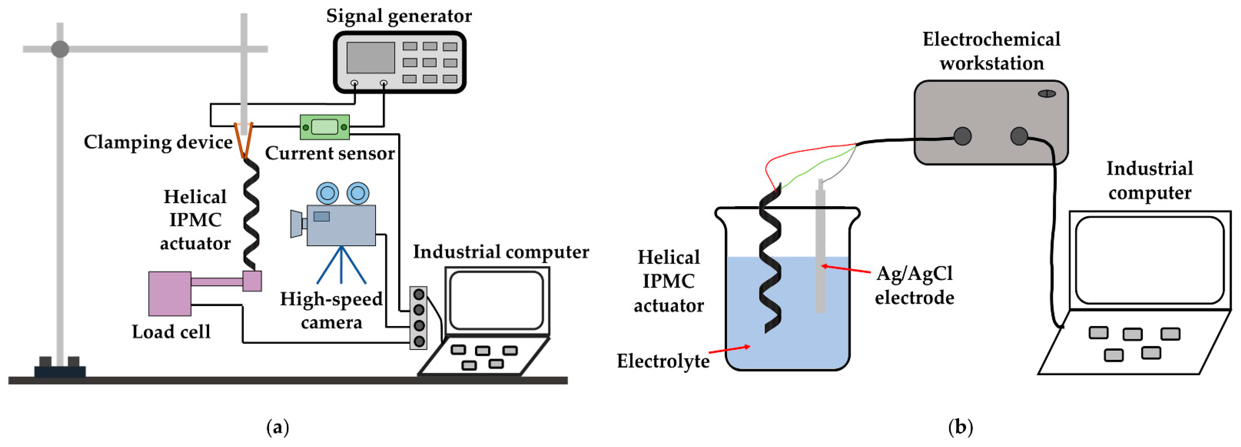
2.3. Experimental Setup
3. Results and Discussions
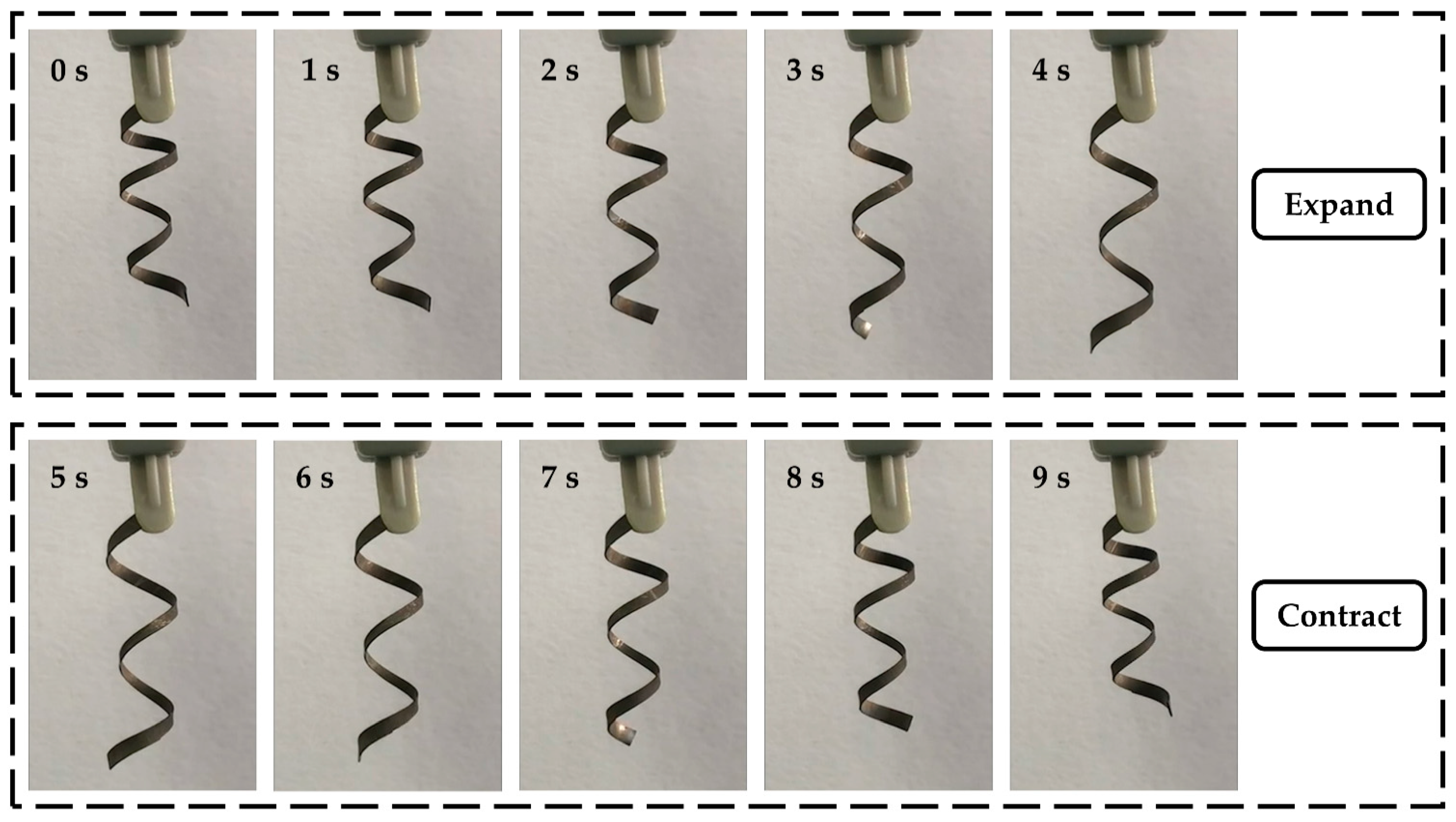
3.1. Actuation Behaviors
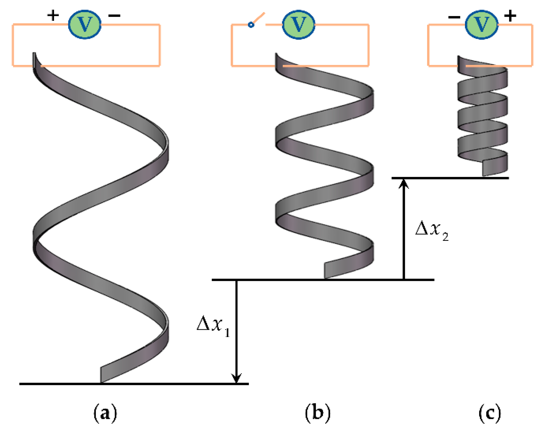
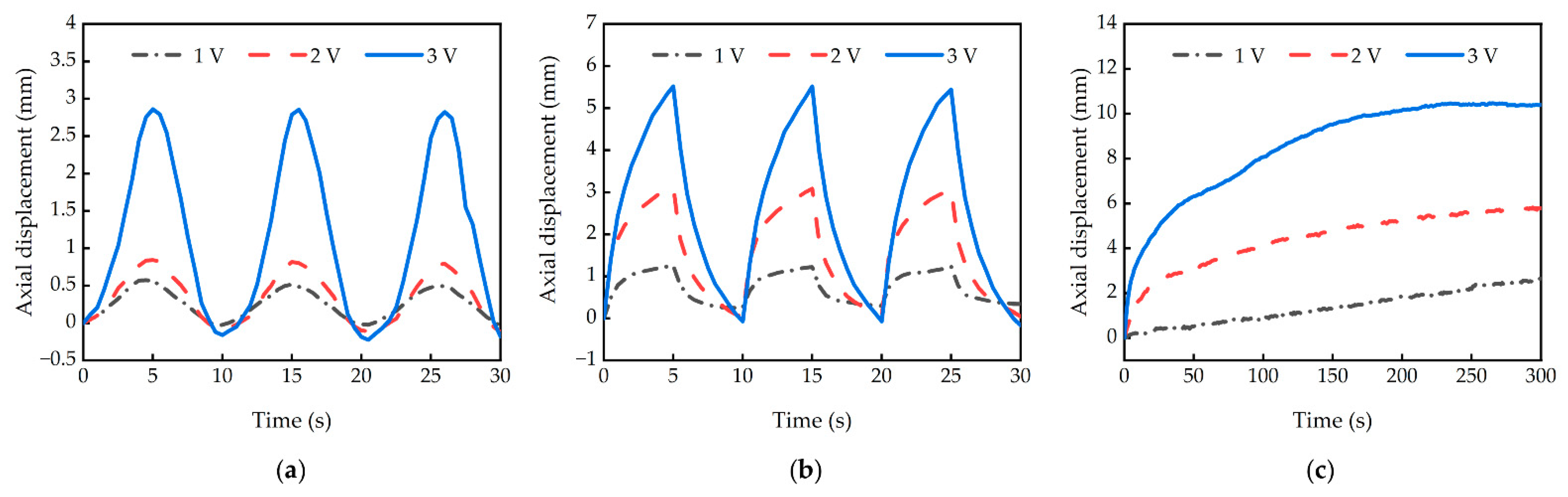
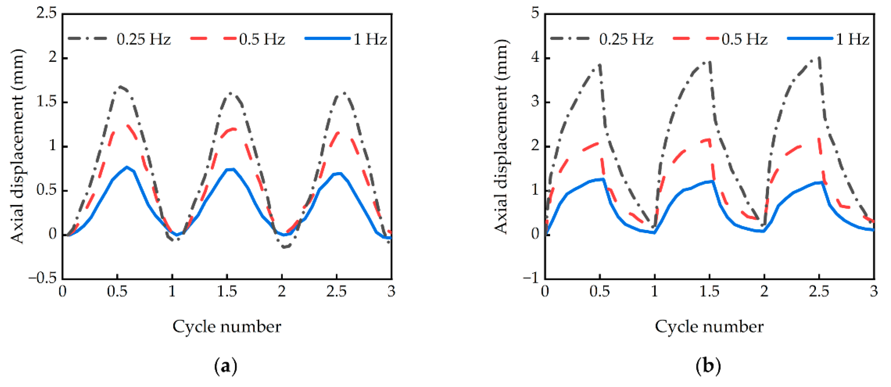
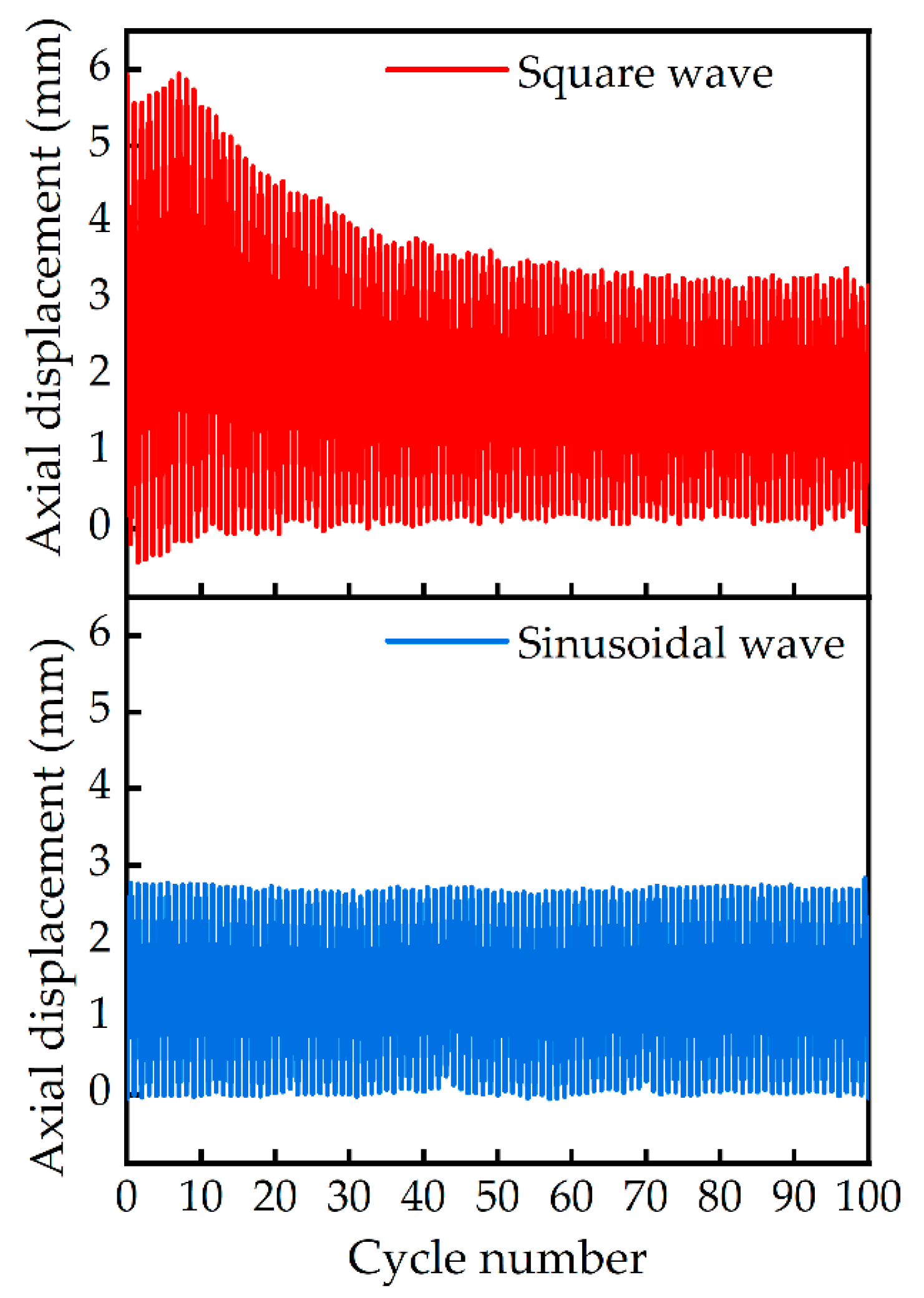
3.2. Displacement Characteristics
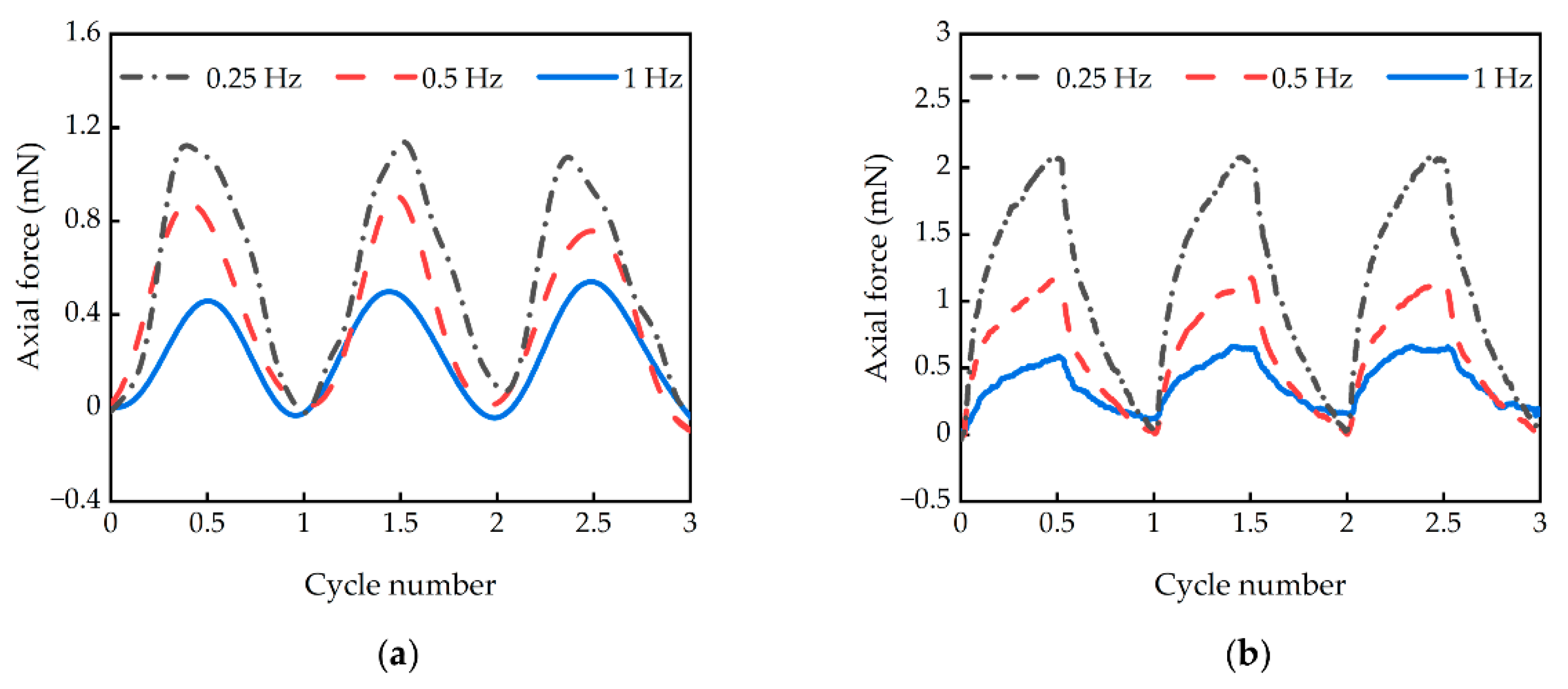
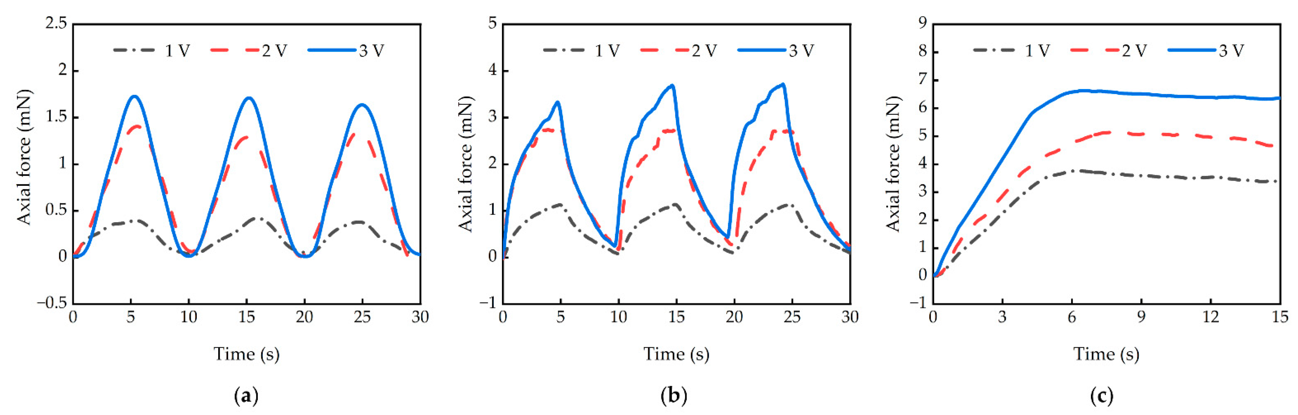
3.3. Force Characteristics
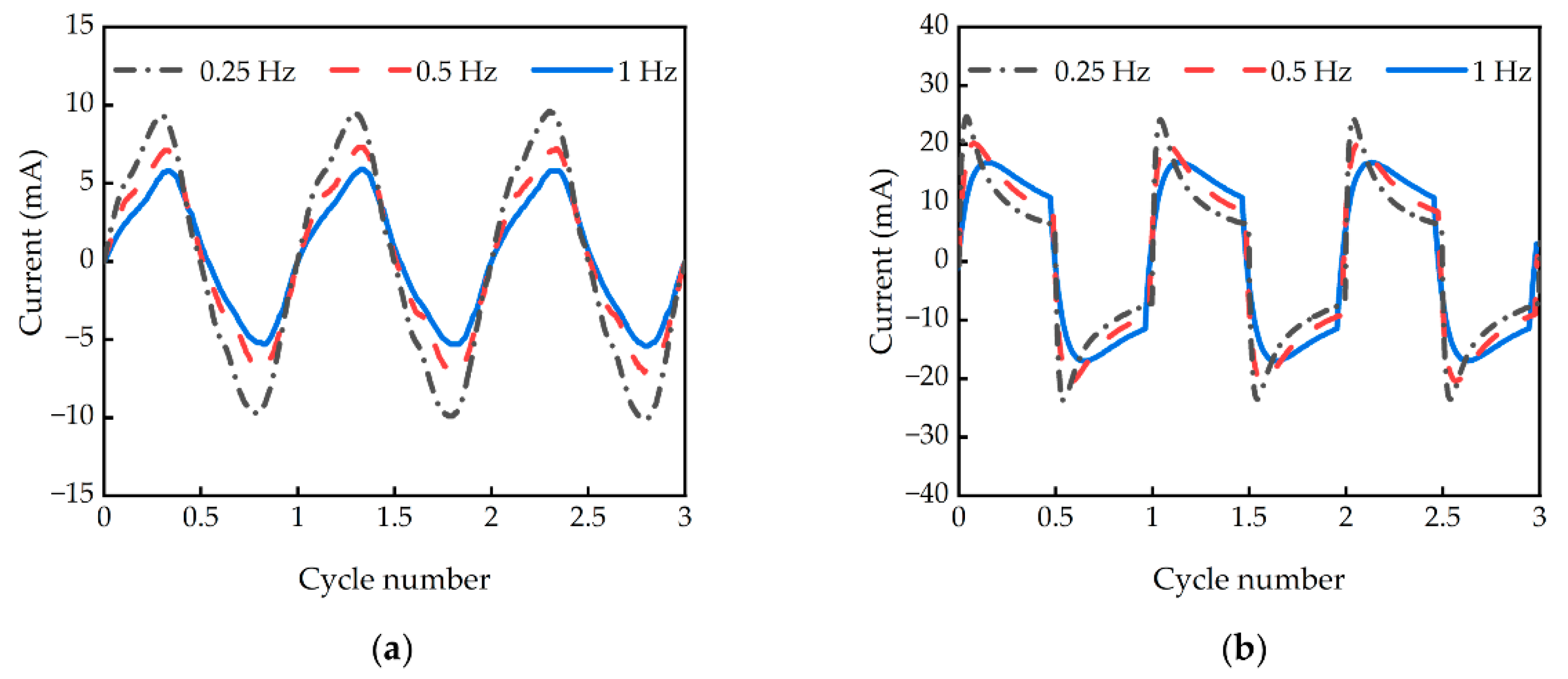
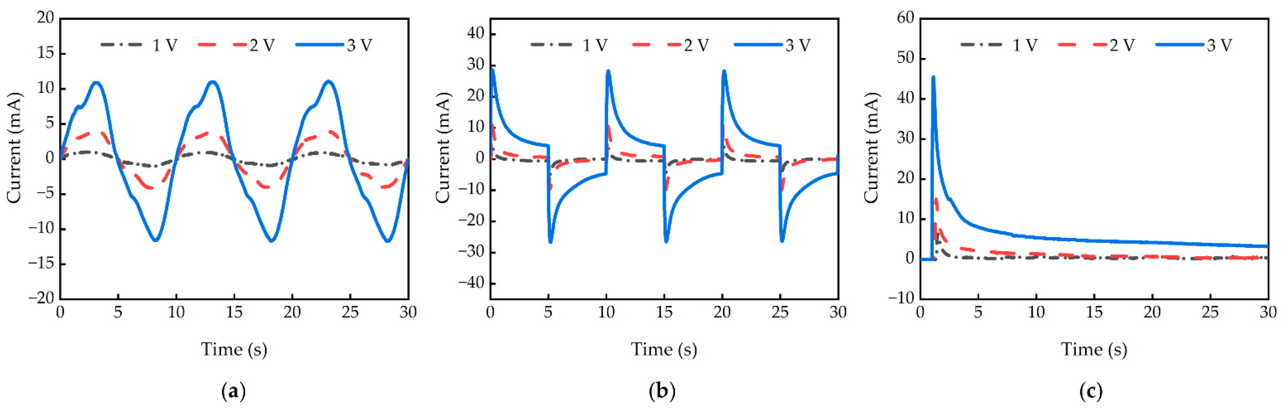
3.4. Electric Current Characteristics
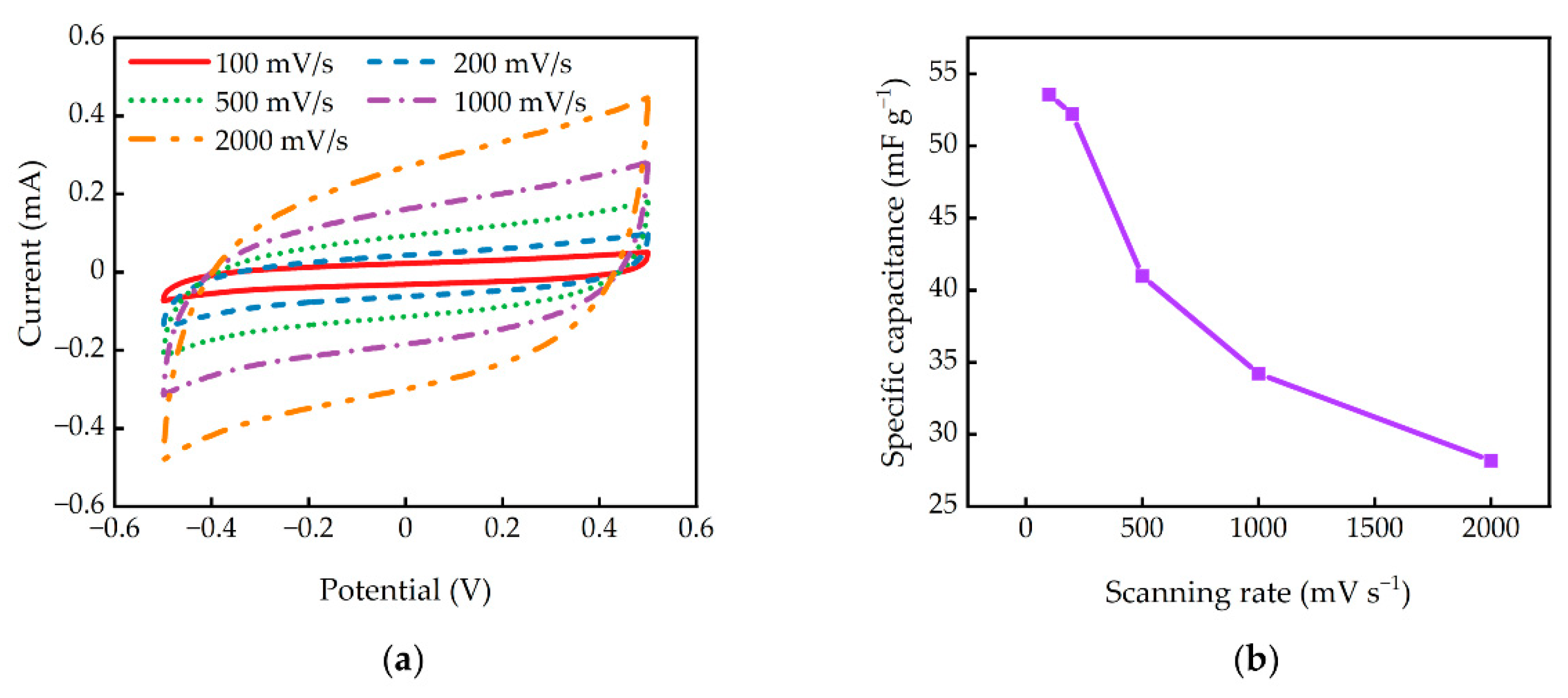
3.5. Electrochemical Characteristics
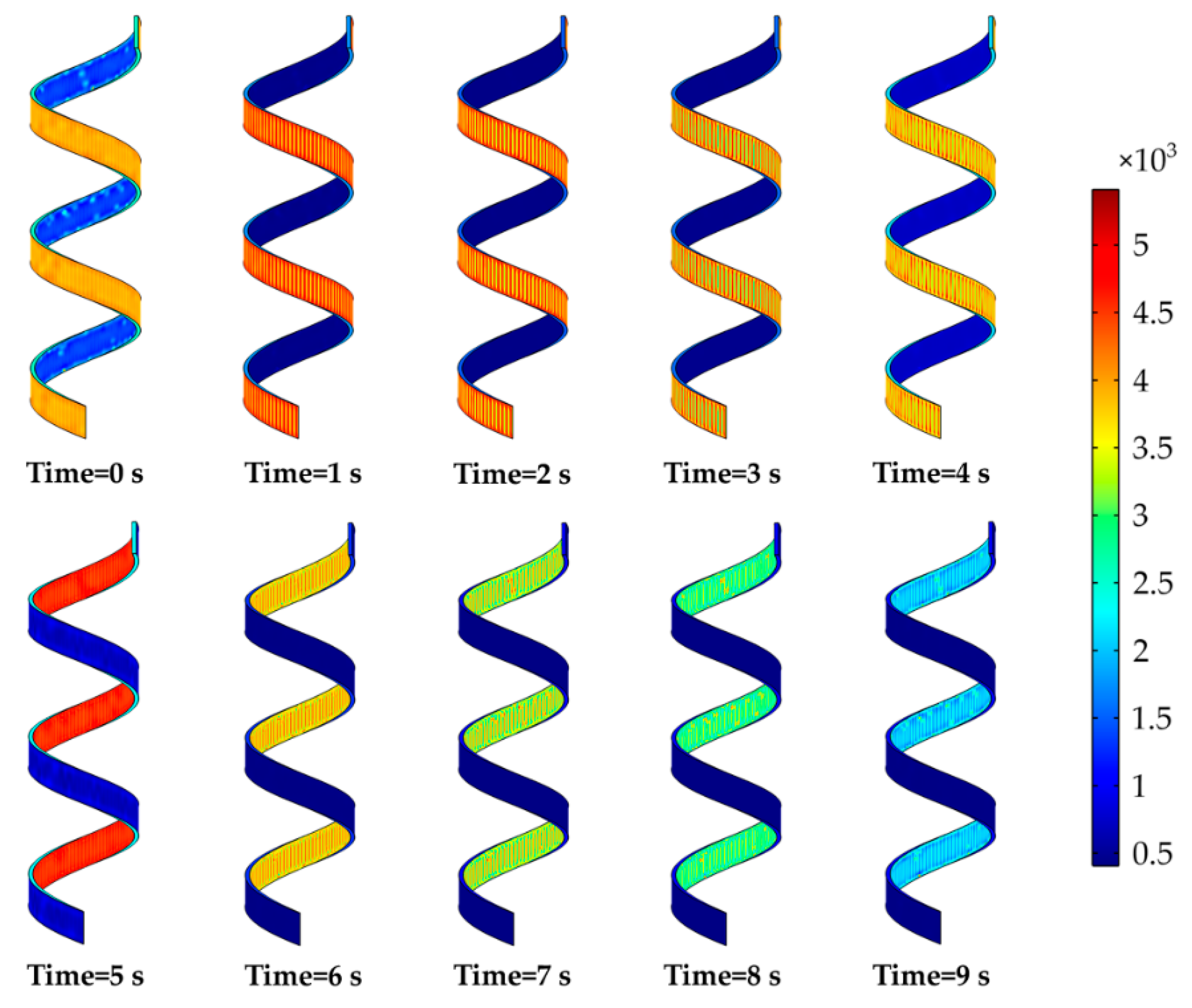
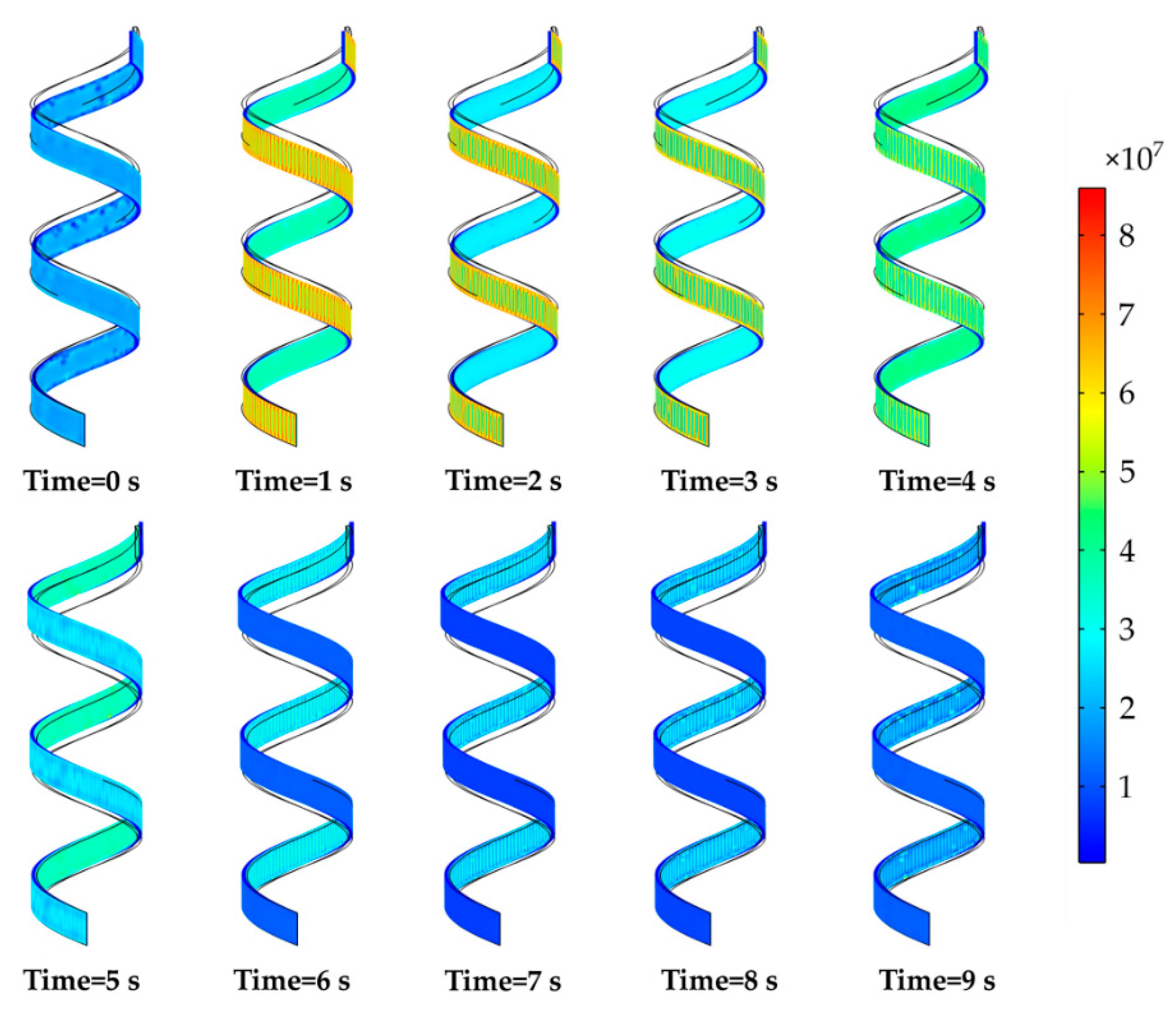
4. Modeling and Simulation
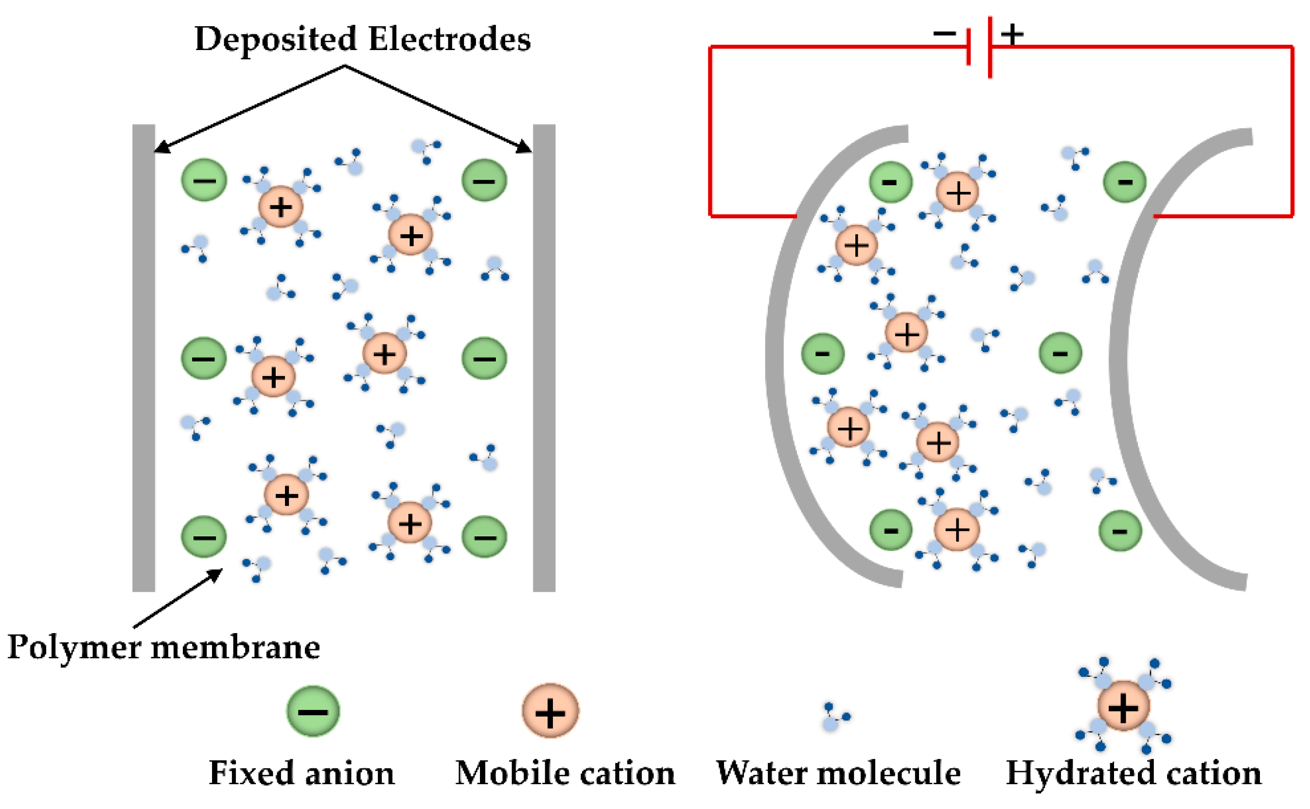
4.1. Mass Transfer Model
4.2. Hygroscopic Swelling Model
4.3. Boundary and Initial Conditions
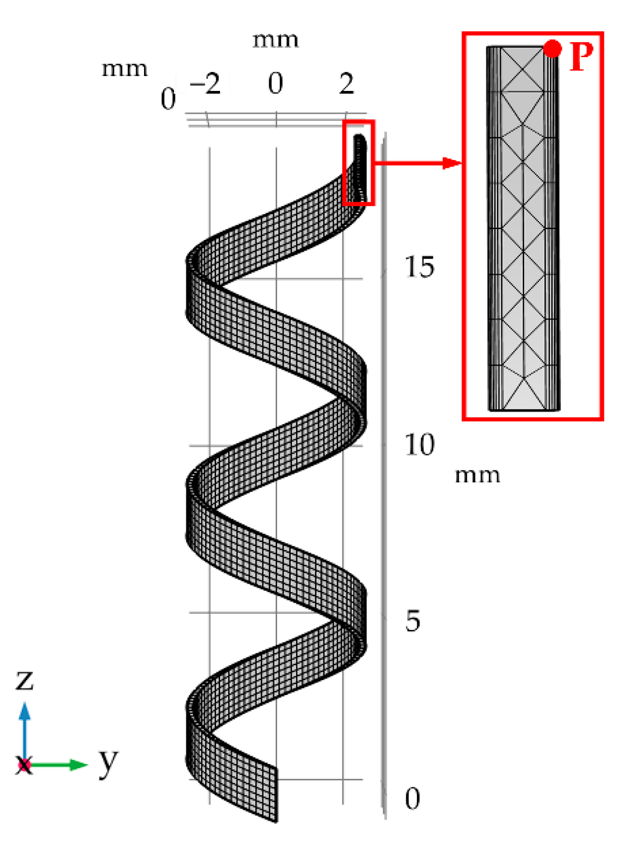
4.4. Model Parameters and Meshing
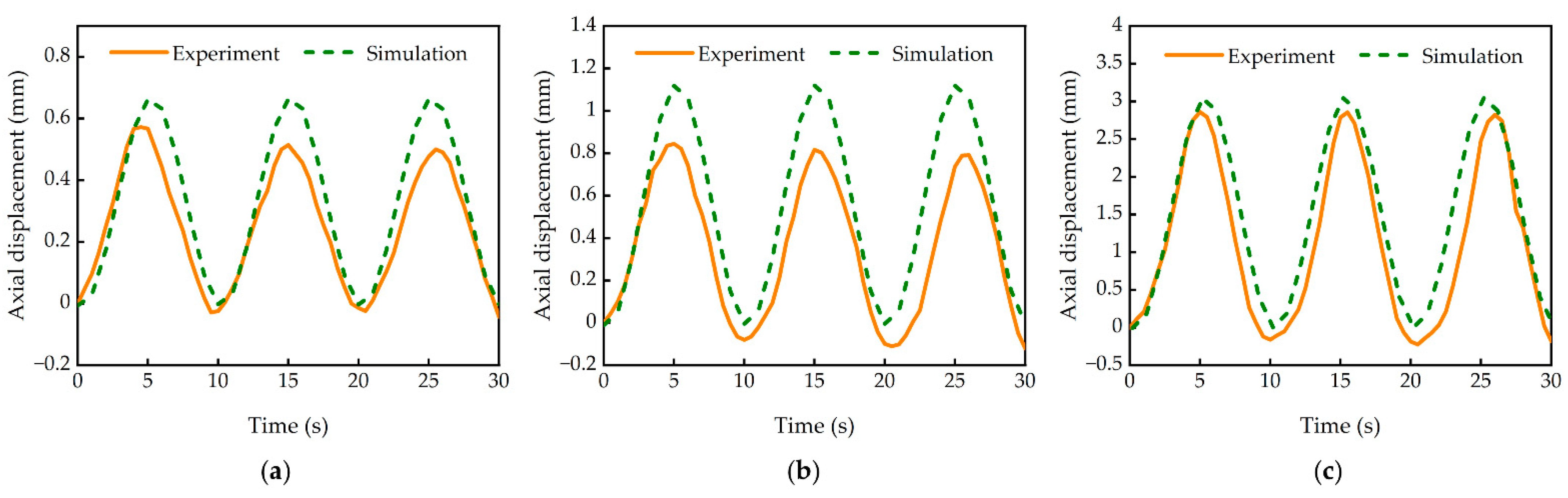
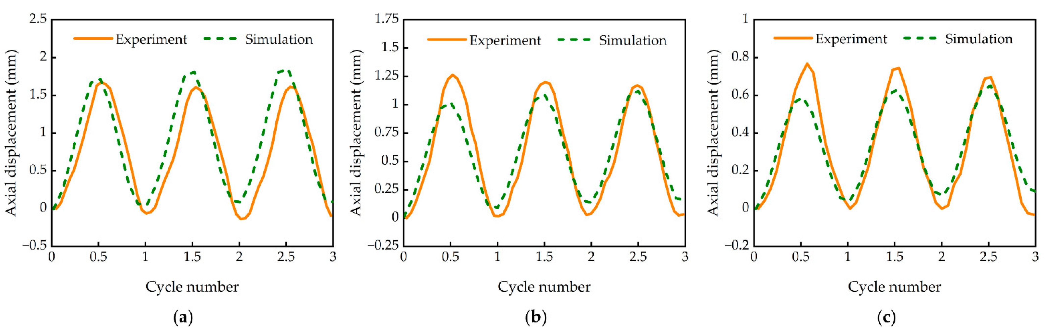
4.5. Data Analysis and Model Verification
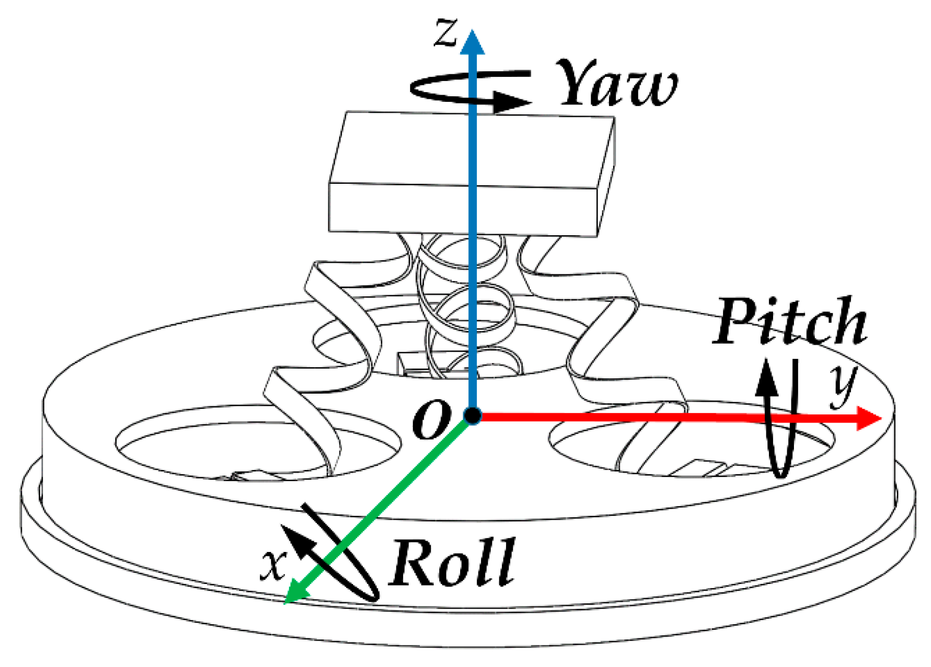
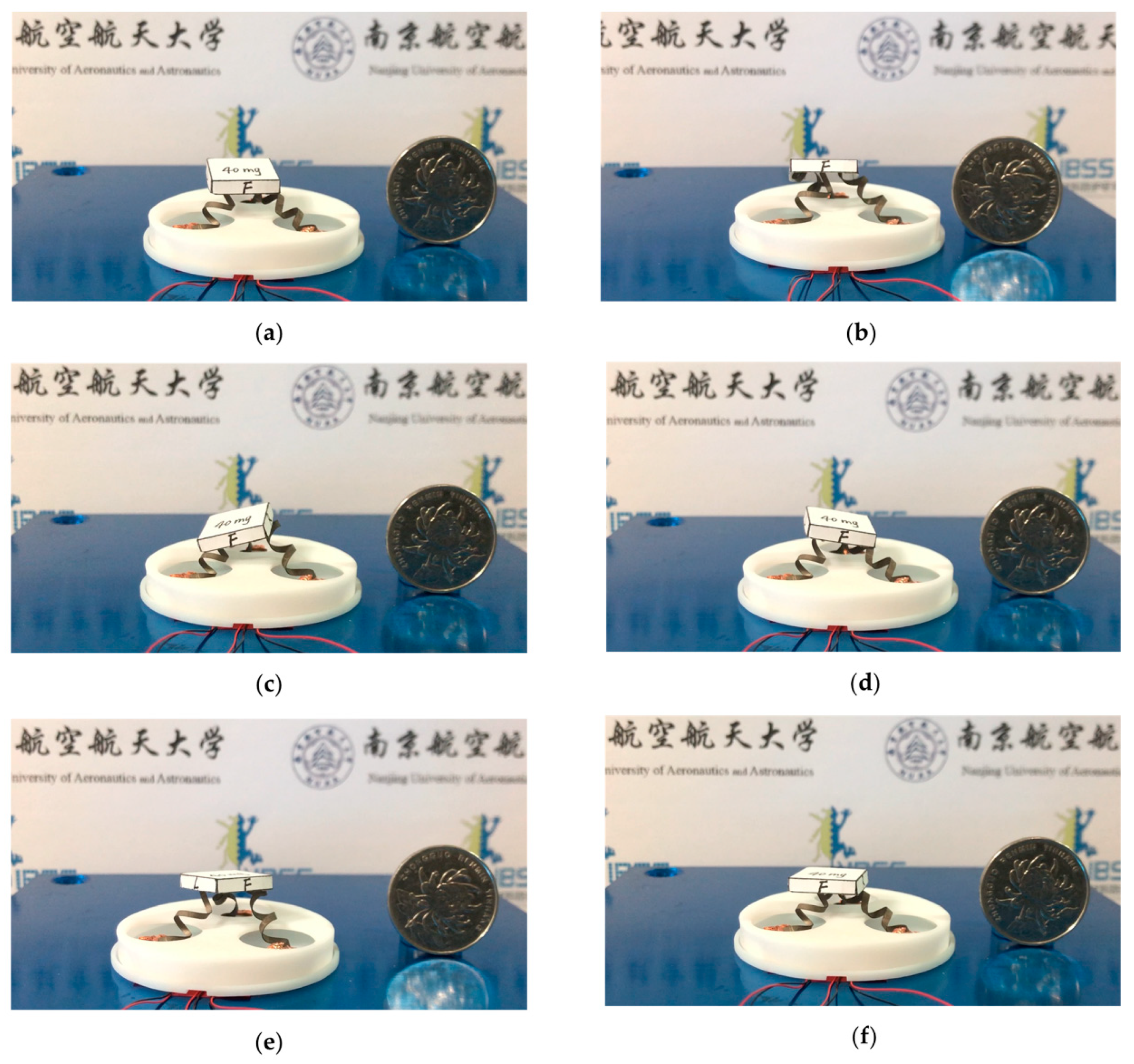
5. Application to a 3-DOF Micro-Parallel Platform
6. Conclusions
Supplementary Materials
Author Contributions
Funding
Institutional Review Board Statement
Informed Consent Statement
Data Availability Statement
Conflicts of Interest
Appendix A

References
- Yan, Y.; Hu, Z.; Zhao, X.; Sun, T.; Dong, S.; Li, X. Top-down nanomechanical machining of three-dimensional nanostructures by atomic force microscopy. Small 2010, 6, 724–728. [Google Scholar] [CrossRef]
- Holub, O.; Spiller, M.; Hurak, Z. Stick-slip based micropositioning stage for transmission electron microscope. In Proceedings of the 9th IEEE International Workshop on Advanced Motion Control, Istanbul, Turkey, 27–29 March 2006; pp. 484–487. [Google Scholar] [CrossRef]
- Hesselbach, J.; Wrege, J.; Raatz, A.; Becker, O. Aspects on design of high precision parallel robots. Assem. Autom. 2004, 24, 49–57. [Google Scholar] [CrossRef]
- Adibnazari, I.; Nagel, W.S.; Leang, K.K. A 3D-printed 3-DOF tripedal microrobotic platform for unconstrained and omnidirectional sample positioning. Int. J. Intell. Robot. 2018, 2, 425–435. [Google Scholar] [CrossRef]
- Li, Y.; Xu, Q. Design and analysis of a totally decoupled flexure-based XY parallel micromanipulator. IEEE Trans. Robot. 2009, 25, 645–657. [Google Scholar] [CrossRef]
- Li, Y.; Xu, Q. Modeling and performance evaluation of a flexure-based XY parallel micromanipulator. Mech. Mach. Theory 2009, 44, 2127–2152. [Google Scholar] [CrossRef]
- Kim, H.S.; Cho, Y.M. Design and modeling of a novel 3-DOF precision micro-stage. Mechatronics 2009, 19, 598–608. [Google Scholar] [CrossRef]
- Kim, H.Y.; Ahn, D.H.; Gweon, D.G. Development of a novel 3-degrees of freedom flexure based positioning system. Rev. Sci. Instrum. 2012, 83, 055114:1–055114:11. [Google Scholar] [CrossRef] [PubMed]
- Li, Y.; Huang, J.; Tang, H. A compliant parallel XY micromotion stage with complete kinematic decoupling. IEEE Trans. Autom. Sci. Eng. 2012, 9, 538–553. [Google Scholar] [CrossRef]
- Seo, T.W.; Kim, H.S.; Kang, D.S.; Kim, J. Gain-scheduled robust control of a novel 3-DOF micro parallel positioning platform via a dual stage servo system. Mechatronics 2008, 18, 495–505. [Google Scholar] [CrossRef]
- Tian, Y.; Shirinzadeh, B.; Zhang, D. Design and dynamics of a 3-DOF flexure-based parallel mechanism for micro/nano manipulation. Microelectron. Eng. 2010, 87, 230–241. [Google Scholar] [CrossRef]
- Rodriguez-Fortun, J.M.; Rotella, F.; Alfonso, J.; Carrillo, F.J.; Orus, J. Model-free control of a 3-DOF piezoelectric nanopositioning platform. In Proceedings of the 52nd IEEE conference on decision and control, Florence, Italy, 10–13 December 2013; pp. 342–347. [Google Scholar]
- Wang, G.; Wang, Y.; Lv, B.; Ma, R.; Liu, L. Research on a new type of rigid-flexible coupling 3-DOF micro-positioning platform. Micromachines 2020, 11, 1015. [Google Scholar] [CrossRef]
- Chen, K.S.; Trumper, D.L.; Smith, S.T. Design and control for an electromagnetically driven X–Y–θ stage. Precis. Eng.-J. Int. Soc. Precis. Eng. Nanotechnol. 2002, 26, 355–369. [Google Scholar] [CrossRef]
- Xiao, S.; Li, Y.; Yang, Q. A novel flexure-based 3-DOF micro-parallel manipulator with a gripper for micro/nano manipulation. In Proceedings of the 6th IFAC Symposium on Mechatronic Systems, Hangzhou, China, 10–12 April 2013; pp. 606–611. [Google Scholar] [CrossRef]
- Xiao, S.; Li, Y. Optimal design, fabrication, and control of an XY micropositioning stage driven by electromagnetic actuators. IEEE Trans. Ind. Electron. 2013, 60, 4613–4626. [Google Scholar] [CrossRef]
- Nakamura, Y.; Nakayama, M.; Masuda, K.; Tanaka, K.; Yasuda, M.; Fujita, T. Development of active six-degrees-of-freedom microvibration control system using giant magnetostrictive actuators. Smart Mater. Struct. 2000, 9, 175–185. [Google Scholar] [CrossRef]
- Sun, X.; Yang, B.; Zhao, L.; Sun, X. Optimal design and experimental analyses of a new micro-vibration control payload-platform. J. Sound Vibr. 2016, 374, 43–60. [Google Scholar] [CrossRef]
- Niu, M.; Yang, B.; Yang, Y.; Meng, G. Modelling and parameter design of a 3-DOF compliant platform driven by magnetostrictive actuators. Precis. Eng. J. Int. Soc. Precis. Eng. Nanotechnol. 2020, 66, 255–268. [Google Scholar] [CrossRef]
- Yan, Y.; Santaniello, T.; Bettini, L.G.; Minnai, C.; Bellacicca, A.; Porotti, R.; Denti, I.; Faraone, G.; Merlini, M.; Lenardi, C.; et al. Electroactive ionic soft actuators with monolithically integrated gold nanocomposite electrodes. Adv. Mater. 2017, 29, 1606109:1–1606109:9. [Google Scholar] [CrossRef] [PubMed]
- Tamagawa, H.; Okada, K.; Mulembo, T.; Sasaki, M.; Naito, K.; Nagai, G.; Nitta, T.; Yew, K.C.; Ikeda, K. Simultaneous enhancement of bending and blocking force of an ionic polymer-metal composite (IPMC) by the active use of its material characteristics change. Actuators 2019, 8, 29. [Google Scholar] [CrossRef] [Green Version]
- Ma, S.; Zhang, Y.; Liang, Y.; Ren, L.; Tian, W.; Ren, L. High-performance ionic-polymer-metal composite: Toward large-deformation fast-response artificial muscles. Adv. Funct. Mater. 2019, 30, 1908508:1–1908508:9. [Google Scholar] [CrossRef]
- Umrao, S.; Tabassian, R.; Kim, J.; Nguyen, V.H.; Zhou, Q.; Nam, S.; Oh, I.K. MXene artificial muscles based on ionically cross-linked Ti3C2Tx electrode for kinetic soft robotics. Sci. Robot. 2019, 4, eaaw7797:1–eaaw7797:11. [Google Scholar] [CrossRef] [PubMed]
- Sun, Z.; Du, S.; Li, F.; Yang, L.; Zhang, D.; Song, W. High-performance cellulose based nanocomposite soft actuators with porous high-conductivity electrode doped by graphene-coated carbon nanosheet. Cellulose 2018, 25, 5807–5819. [Google Scholar] [CrossRef]
- Wang, Y.; Liu, J.; Zhu, D.; Chen, H. Active tube-shaped actuator with embedded square rod-shaped ionic polymer-metal composites for robotic-assisted manipulation. Appl. Bionics Biomech. 2018, 2018, 4031705:1–4031705:12. [Google Scholar] [CrossRef] [Green Version]
- Yu, M.; Shen, H.; Dai, Z. Manufacture and performance of ionic polymer-metal composites. J. Bionic Eng. 2007, 4, 143–149. [Google Scholar] [CrossRef]
- Kim, K.J.; Shahinpoor, M. Ionic polymer-metal composites: II. Manufacturing techniques. Smart Mater. Struct. 2003, 12, 65–79. [Google Scholar] [CrossRef]
- Li, S.L.; Kim, W.Y.; Cheng, T.H.; Oh, I.K. A helical ionic polymer-metal composite actuator for radius control of biomedical active stents. Smart Mater. Struct. 2011, 20, 035008:1–035008:8. [Google Scholar] [CrossRef]
- Shahinpoor, M. Smart ionic polymer conductor composite materials as multifunctional distributed nanosensors, nanoactuators and artificial muscles. In Proceedings of the ASME International Mechanical Engineering Congress and Exposition, Orlando, FL, USA, 5–11 November 2005; pp. 485–489. [Google Scholar]
- Feng, G.H.; Zhan, Z.H. A room-temperature processed parylene-patterned helical ionic polymer-metal composite spring actuator with selectable active region. Smart Mater. Struct. 2014, 23, 045002:1–045002:13. [Google Scholar] [CrossRef]
- Wang, M.; Yu, M.; Lu, M.; He, Q.; Ji, K.; Liu, L. Effects of Cu2+ counter ions on the actuation performance of flexible ionic polymer metal composite actuators. J. Bionic Eng. 2018, 15, 1047–1056. [Google Scholar] [CrossRef]
- Shahinpoor, M.; Kim, K.J. Ionic polymer-metal composites: I. Fundamentals. Smart Mater. Struct. 2001, 10, 819–833. [Google Scholar] [CrossRef]
- Wang, F.; Li, Q.; Park, J.O.; Zheng, S.; Choi, E. Ultralow voltage high-performance bioartificial muscles based on ionically crosslinked polypyrrole-coated functional carboxylated bacterial cellulose for soft robots. Adv. Funct. Mater. 2020, 31, 2007749:1–2007749:10. [Google Scholar] [CrossRef]
- He, Q.; Yu, M.; Li, Y.; Ding, Y.; Guo, D.; Dai, Z. Investigation of ionic polymer metal composite actuators loaded with various tetraethyl orthosilicate contents. J. Bionic Eng. 2012, 9, 75–83. [Google Scholar] [CrossRef]
- Takeuchi, I.; Asaka, K.; Kiyohara, K.; Sugino, T.; Terasawa, N.; Mukai, K.; Shiraishi, S. Electromechanical behavior of a fully plastic actuator based on dispersed nano-carbon/ionic-liquid-gel electrodes. Carbon 2009, 47, 1373–1380. [Google Scholar] [CrossRef]
- Chen, Z.; Tan, X. A control-oriented and physics-based model for ionic polymer-metal composite actuators. IEEE-ASME Trans. Mechatron. 2008, 13, 519–529. [Google Scholar] [CrossRef]
- He, Q.; Yu, M.; Song, L.; Ding, H.; Zhang, X.; Dai, Z. Experimental study and model analysis of the performance of IPMC membranes with various thickness. J. Bionic Eng. 2011, 8, 77–85. [Google Scholar] [CrossRef]
- Shen, Q.; Palmre, V.; Stalbaum, T.; Kim, K.J. A comprehensive physics-based model encompassing variable surface resistance and underlying physics of ionic polymer-metal composite actuators. J. Appl. Phys. 2015, 118, 124904:1–124904:12. [Google Scholar] [CrossRef]
- Vokoun, D.; He, Q.; Heller, L.; Yu, M.; Dai, Z. Modeling of IPMC cantilever’s displacements and blocking forces. J. Bionic Eng. 2015, 12, 142–151. [Google Scholar] [CrossRef]
- Tadokoro, S.; Yamagami, S.; Takamori, T.; Oguro, K. Modeling of Nafion-Pt composite actuators (ICPF) by ionic motion. In Proceedings of the Smart Structures and Materials 2000: Electroactive Polymer Actuators and Devices, Newport Beach, CA, USA, 5–9 March 2000; pp. 92–102. [Google Scholar] [CrossRef]
- De Gennes, P.G.; Okumura, K.; Shahinpoor, M.; Kim, K.J. Mechanoelectric effects in ionic gels. EPL 2000, 50, 513–518. [Google Scholar] [CrossRef] [Green Version]
- Nemat-Nasser, S.; Li, J.Y. Electromechanical response of ionic polymer-metal composites. J. Appl. Phys. 2000, 87, 3321–3331. [Google Scholar] [CrossRef]
- Espinoza-Quinones, F.R.; Romani, M.; Borba, C.E.; Modenes, A.N.; Utzig, C.F.; Dall’Oglio, I.C. A mathematical approach based on the Nernst-Planck equation for the total electric voltage demanded by the electrocoagulation process: Effects of a time-dependent electrical conductivity. Chem. Eng. Sci. 2020, 220, 115626:1–115626:15. [Google Scholar] [CrossRef]
- Zhang, Q.; Tu, B.; Fang, Q.; Lu, B. A structure-preserving finite element discretization for the time-dependent Nernst-Planck equation. J. Appl. Math. Comput. 2021, 1–20. [Google Scholar] [CrossRef]
- Warren, P.B. Non-faradaic electric currents in the Nernst-Planck equations and nonlocal diffusiophoresis of suspended colloids in crossed salt gradients. Phys. Rev. Lett. 2020, 124, 248004:1–248004:5. [Google Scholar] [CrossRef]
- Chidiac, S.E.; Shafikhani, M. Electrical resistivity model for quantifying concrete chloride diffusion coefficient. Cem. Concr. Compos. 2020, 113, 103707:1–338414:12. [Google Scholar] [CrossRef]
- Goona, N.K.; Parne, S.R.; Sashidhar, S. Distributed Source Scheme to solve the classical form of Poisson equation using 3-D Finite-Difference Method for improved accuracy and unrestricted source position. Math. Comput. Simul. 2021, 190, 965–975. [Google Scholar] [CrossRef]
- Peng, H.; Hui, Y.; Ding, Q.; Li, H.; Zhao, C. IPMC gripper static analysis based on finite element analysis. Front. Mech. Eng. 2010, 5, 204–211. [Google Scholar] [CrossRef]


| Diameter (mm) | Pitch (mm) | Length (mm) | Width (mm) | Weight (mg) |
|---|---|---|---|---|
| 5.00 | 6.47 | 20.09 | 1.49 | 20.2 |
| Variable/Constant | Value and Unit |
|---|---|
| Faraday constant, F | 96,485.332 C/mol |
| Mobility, μ | s·mol/kg |
| Diffusion coefficient, D | m2/s |
| Charge number, z | 1 |
| Permittivity of Nafion membrane, ε | F/m |
| Concentration of anions, C0 | 1000 mol·m3 |
| Absolute temperature, T | 293 K |
| Young’s modulus of IPMC, EIPMC | 0.5 GPa |
| Poisson’s ratio of IPMC, νIPMC | 0.487 |
| Density of IPMC, ρIPMC | 2600 kg/m3 |
| Molar mass of cations, M | 0.0789 kg/mol |
| Hygroscopic swelling coefficient, βh | m3/kg |
| Amplitude of applied voltage, A | 1 V, 2 V, 3 V |
| Frequency of applied voltage, f | 0.25 Hz, 0.5 Hz, 1 Hz |
Publisher’s Note: MDPI stays neutral with regard to jurisdictional claims in published maps and institutional affiliations. |
© 2021 by the authors. Licensee MDPI, Basel, Switzerland. This article is an open access article distributed under the terms and conditions of the Creative Commons Attribution (CC BY) license (https://creativecommons.org/licenses/by/4.0/).
Share and Cite
Wu, Y.; Yu, M.; He, Q.; Vokoun, D.; Yin, G.; Xu, X.; Lyu, P. Axial Motion Characterization of a Helical Ionic Polymer Metal Composite Actuator and Its Application in 3-DOF Micro-Parallel Platforms. Actuators 2021, 10, 248. https://doi.org/10.3390/act10100248
Wu Y, Yu M, He Q, Vokoun D, Yin G, Xu X, Lyu P. Axial Motion Characterization of a Helical Ionic Polymer Metal Composite Actuator and Its Application in 3-DOF Micro-Parallel Platforms. Actuators. 2021; 10(10):248. https://doi.org/10.3390/act10100248
Chicago/Turabian StyleWu, Yuwei, Min Yu, Qingsong He, David Vokoun, Guoxiao Yin, Xianrui Xu, and Pengfei Lyu. 2021. "Axial Motion Characterization of a Helical Ionic Polymer Metal Composite Actuator and Its Application in 3-DOF Micro-Parallel Platforms" Actuators 10, no. 10: 248. https://doi.org/10.3390/act10100248